1. Introduction
A badminton shuttlecock flies very fast, initially over 80 m/s, and soon decreases its speed to under 10 m/s in 0.6 s in 10 m as it flies toward the opponent. Such flight characteristics are never seen in other sports. A badminton shuttle consists of two parts: a cork, which forms the head and 15 to 16 natural waterfowl feathers. The shape of a badminton cork is hemispherical; thus, it can be considered to be a bluff body. Cooke examined shuttlecock aerodynamics in a wind tunnel experiment [
1] and calculated the trajectory of the shuttle using experimental results to match its actual flight trajectory [
2]. Since then, many researchers have studied aerodynamic drag using experiments and computational fluid dynamics (CFD) analysis for a wide speed range, or to clarify the difference between feather shuttlecocks and synthetic shuttlecocks [
3,
4,
5,
6,
7,
8,
9]. However, studies on lift effects are limited [
1,
5,
7]. The lift force and pitching moment are also important factors to be considered in terms of the aerodynamic stability of a badminton shuttlecock, especially in the turnover [
9].
It is well known that a shuttle rotating at a high angular rotation rate, that is a shuttle traveling at high speeds—spreads its skirt from centrifugal force, thereby increasing drag. On the other hand, shuttles without rotation and synthetic shuttles with thin blades and insufficiently rigid skirts shrink their skirts due to wind pressure, thereby decreasing the drag. [
1,
3,
4]. It has been considered that the change in drag depends only on the change of the projected area of the shuttle’s skirt. However, these deformations not only increase or decrease the projected area of the skirt, but also increase or decrease the camber of the blade. Considering the blade of the shuttlecock as an airfoil, its cross-sectional form is almost a flat plate. In other words, it has no cambered symmetrical airfoil. Usually, an increase in the camber of an airfoil changes its aerodynamics. Thus, we should consider both the change in the projected area of the skirt and the effect of the chamber of the blade.
In this study, we investigate the effects of the camber of the skirt using wind tunnel experiments and CFD analysis. The study demonstrates that the aerodynamics of a shuttlecock can be modified by adding camber to the skirt.
2. Methods
The experiment was conducted at the small low-turbulence wind tunnel at the Institute of Fluid Science, Tohoku University, Japan. The test section was octagonal with 293 mm opposite distances. The experiment was conducted at a closed test section. The wind tunnel is the same as in Kitta et al. [
3] and Nakagawa et al. [
4], except for the test section. In their experiment, an open-type test section was used.
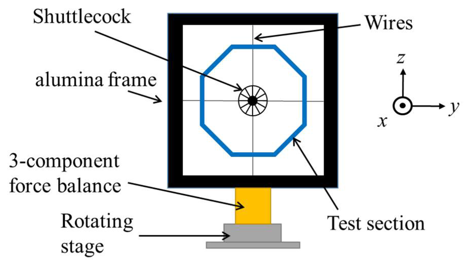
Figure 1 shows the experimental setup to measure the forces acting on a shuttlecock. The shuttlecock was supported at the center of the test section of the cork by two horizontally and vertically arranged thin wires with a diameter of 0.5 mm. These wires were attached to an aluminum frame surrounding the test section. The tension of the wires was controlled by screws positioned at the end of the wire. The frame was attached to a three-component balance (LMC-3501-50N, Nissho Electric Co., Ltd., Tokyo, Japan). The setup was similar to the experimental setup for measuring the negative Magnus force on a sphere, conducted by Konishi et al. [
10]. The force balance was located on the rotary stage, KSA-160PM, Sigma Koki Co., Ltd., Tokyo, Japan, to measure various angles of attack. Measurements were conducted from −24° to 24°. The output signal of the force balance was acquired for 10 s with a sampling rate of 1 kHz. The measured data was averaged to obtain the mean values. The measured value includes the drag of the supporting wires. Therefore, the drag of the wires was subtracted. Each measurement value—for instance, 0.5 N for drag—is much smaller than the range of the force balance, e.g., 50 N. Thus, the balance was calibrated to verify the linearity and accuracy using a pulley and weight before conducting the measurement. The total error, which consists of non-linearity and hysteresis, was approximately 0.7% in the range between 0 and 0.5 N for force and 0.16% in the range between 0 and 0.14 Nm for the pitching moment.
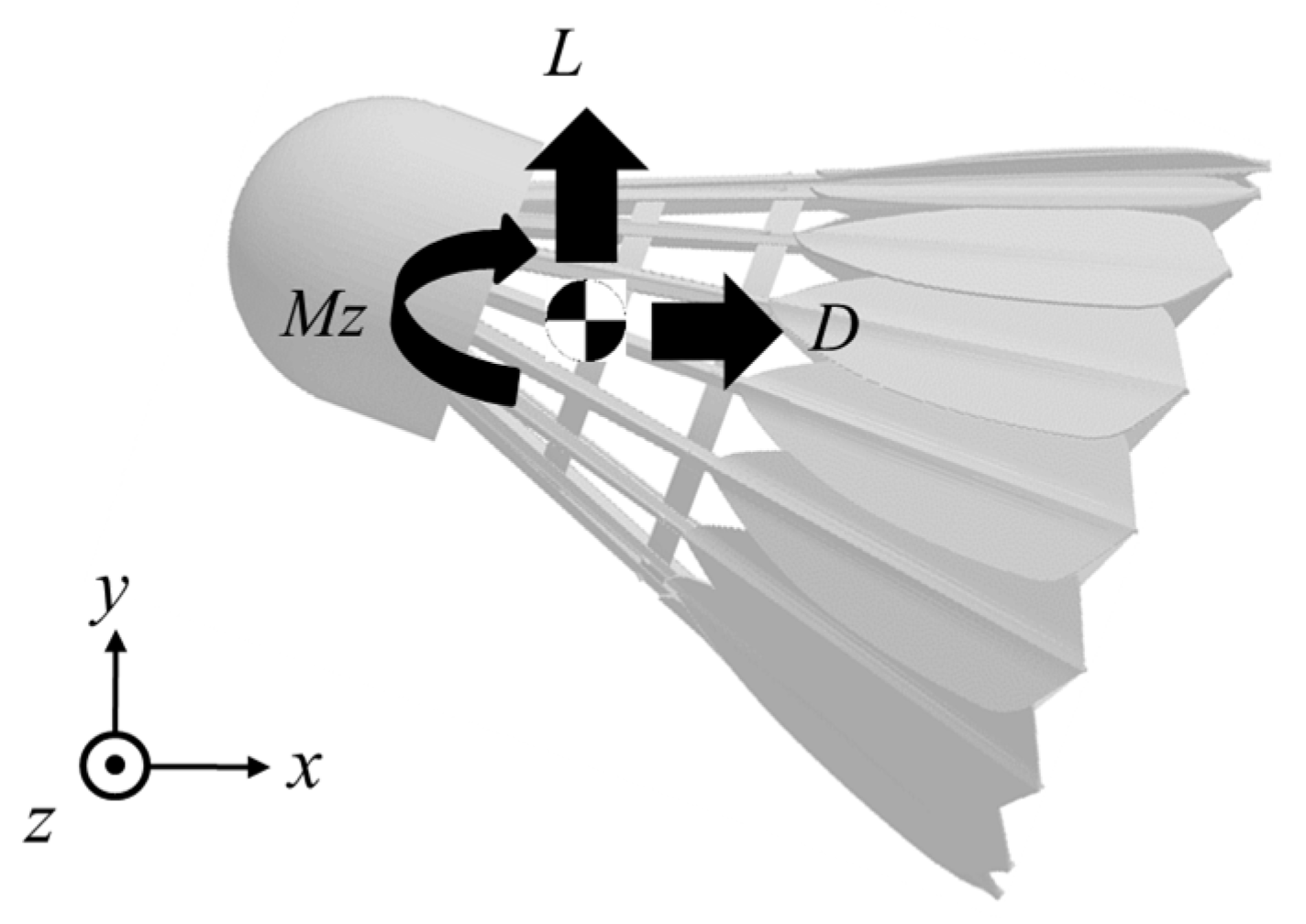
Figure 2 shows the coordinate system, in which
x is the stream-wise direction,
y is the span-wise direction, and
z is the normal-to-wall direction. The origin was set as the center of mass of the shuttlecock without camber. The center of mass is located just behind the cork. Therefore, the center of the supported wire and balance did not match the origin. The angle of attack,
α, is defined as the angle between a reference line of the shuttlecock and the stream-wise direction. The lift,
L, the drag,
D, and the pitching moment,
Mz, are also shown in
Figure 2. The pitching moment,
Mz, was calculated after the measurements using the distance between the supported center and the origin. The pitching moment is defined as the moment when the nose is up in the
y-positive direction. Each coefficient,
CL,
CD,
Cm is defined as follows:
where
d is the diameter of the shuttlecock skirt,
L is the length of the shuttlecock,
U is the uniform velocity, and
is the density of the air.
The head of the model was made of aluminum and each blade of the skirt was made with rapid prototyping such that the shape of the blade can be easily changed. A total of five models were tested. The normal model had a half vertex angle of skirt of approximately 22°, and width and length of 68 mm and 85 mm, respectively. Camber was added to only the blade to avoid a change in the width of the skirt as shown in
Figure 3. This ensures that the effect of the camber can be easily extracted. The height of the camber,
h, was selected as 2.4 mm and 3.6 mm, corresponding to approximately 6% and 9% of the chord length of the blade. For convenience, positive camber indicates concavity (
Figure 3b) and negative camber indicates convexity (
Figure 3c).
Figure 3 shows the three types of camber models.
A study of the spinning effect reveals that the variation of the drag coefficient against velocity is due to the deformation of the skirt, and the reduction of the drag coefficient at the non-spinning condition is followed by a reduction in the diameter of the skirt [
7]. For our purpose, these conditions should be avoided. We conducted the experiment at a low speed,
U∞ = 10 m/s, without rotation, in order to avoid substantial deformation of the prototype blade. This corresponds to a Reynolds number,
Re, of 4.6 × 10
4 based on the skirt diameter.
To understand the flow characteristics around the shuttlecock, numerical analysis was also carried out for three models,
h = −3.6 mm, 0.0 mm, and 3.6 mm. ANSYS Fluent software was used for the analysis with the three-dimensional incompressible steady case. The semi-implicit method for the pressure-linked equation (SIMPLE) was used to couple the velocity and pressure. The second-order upwind difference scheme, which linearly reconstructs the physical variables, was applied to the advection term and viscosity term. The turbulence model was the k-
ω SST model. The mesh was generated in a spherical outer domain with mixed-element grid generation in three dimensions (MEGG3D), which was developed in collaboration with Tohoku University and the Japan Aerospace Exploration Agency (JAXA) [
11,
12,
13]. The mesh points of the surface of the model are selectable by assigning the distribution of the mesh points on feature lines extracted from STL data in MEGG3D. The mesh consists of approximately 4.0 million unstructured hybrids of tetrahedral elements, pyramid elements, and prism elements.
3. Results and Discussions
Figure 4a–c show the lift, drag, and pitching moment coefficient against the angle of attack, respectively. For the base model (i.e., with the camber set to zero), the trend of each coefficient value is almost the same as the results from other experimental studies, such as Cooke [
5] and Hasegawa et al. [
6]. An insensitive region in the lift coefficient was observed around
α = 0 for the negative camber case; furthermore, the drag coefficient increased at the same time. The behavior of a shuttle will not be uniquely determined as a result of such an insensitive region. The presence of this insensitive region in the lift and pitching moment leads to an unsteady flick of the shuttlecock in actual flight. This corresponds to the situation where the strength of each blade is too weak and deforms to enlarge the skirt. On the other hand, the slope of the
CL,
CL/
α, is slightly increased when the camber is set to positive,
h = 3.6 mm. Thus, increasing the camber toward the positive direction causes an increase in the lift force on the skirt. The drag of the shuttlecock decreased at all angles of attack, and a large decrease was observed at
α = 0. The pitching moment coefficient showed the same trend exhibited by the lift coefficient. This suggests that the pitching moment of the shuttlecock is governed by the product of the distance between the aerodynamic center of the skirt and the lift coefficient of the skirt.
Figure 5 compares three models at
α = 0° by a contour map of the averaged velocity component,
U. The outer flow follows the camber line of the blade. Therefore, the wake of the positively cambered model was narrower than other models, resulting in decreased drag. By contrast, the wake of the negatively cambered model was much wider, resulting in increased drag. The former describes a situation when a shuttlecock without rotation deforms at high velocity, whereas the latter describes a situation when a shuttlecock with rotation deforms at high velocity.
Figure 6 shows the pressure distribution around the blade at
α = 0° obtained from CFD analysis. In this figure, the result of a two-dimensional thin airfoil calculated by XFLR5 [
14] based on the panel method developed as XFOIL is also shown for comparison. The characteristics of each distribution is similar to that of the two-dimensional case. Consequently, each blade functions as an airfoil. Each blade is at 22° against the flow direction for the initial spread angle of the skirt. Therefore, the distribution of the suction side, that is, inside the blade, was rather flat. On the other hand, the distribution of the pressure side showed a large difference. The blade with negative camber showed high pressure, almost in the entire region. Thus, the blade catches the wind, similar to the cup anemometer. Most of the lift force was produced by the normal force of the outer surface.
Figure 7 compares the pressure distribution of the upper and lower blades of each model at
α = 25°. Under this condition, the upper blade has an angle of −3° in the
x-direction and the lower blade has an angle of 47° in the
x-direction. As we can imagine, the lower blade is in stall condition. If the upper blade exists as a single airfoil, it must be changing the pressure side and the suction side. In other words, the inside of the blade becomes the pressure side, and outside of the blade becomes the suction side. However, this did not occur, even when there was no lift. This is because the upper blade is in the wake of the cork.
4. Conclusions
The effects of camber on a shuttlecock were studied to determine the aerodynamics of a shuttlecock using wind tunnel experiments and computational fluid dynamics. We verified that the aerodynamics of a shuttlecock can be modified by adding camber to the shuttle’s skirt. Negative camber, which represents bending the blade convexly, increased drag at α = 0°, and an insensitive region of lift around α = 0° was observed. This situation is similar to a shuttlecock with rotation at high velocity. By contrast, positive camber, which represents bending the blade concavely, decreased drag and slightly increased the lifting slope. Each blade, located at the top and bottom of the shuttlecock, represents almost the same pressure distribution as a two-dimensional airfoil. However, in most cases, they were in stall condition. That is, there was insufficient lift force for it to operate as an airfoil even when the upper blade was at a low angle of attack. This is because the upper blade is in the wake of the cork located in front of the shuttlecock under such conditions. The results of this research can contribute to the design of new shuttlecocks.

 ,
, 