Proceeding Paper

Development of an Archery Robot for the Selection of Arrows †

1
Department of Mechanical and Physical Engineering, Osaka City University, Osaka 558-8585, Japan
2
Research Center for Urban Health and Sports, Osaka City University, Osaka 558-8585, Japan
*
Author to whom correspondence should be addressed.
Presented at the 13th conference of the International Sports Engineering Association, Online, 22–26 June 2020.
Proceedings 2020, 49(1), 115; https://doi.org/10.3390/proceedings2020049115
Published: 15 June 2020

Abstract

:
The appropriate selection of arrows in the sport of archery is important to the achievement of high-quality results. In this regard, a shooting machine that is compatible with the wide variety of available bows and arrows is necessary. However, bow strength and arrow length vary among different athletes. It is also important to develop a shooting machine that reproduces the movement of the right fingers that releases an arrow, and the forward jump of a bow after shooting an arrow. In this study, a shooting machine was developed that considered these factors. Its efficacy was examined in terms of its ability to determine the characteristics of each arrow, and to distinguish between normal and flawed arrows. Based on the experimental results, we identified the factors that affected the shooting accuracy of arrows. In addition, the developed shooting machine was able to distinguish between normal and flawed arrows.

1. Introduction

The objective of this study was to design and test a shooting machine to identify flawed arrows that are unsuitable for use at championship events. Archery has been adopted as one of the official sporting events at the Olympics. In Japan, numerous archers have been active participants in world cup or championship events in recent years. This is due in part to the support provided by the All Japan Archery Federation for athletes. At the 2020 Tokyo Olympics, Japanese archers are expected to contend for medals. One’s performance in the game of archery is significantly dependent on mental preparation. If archers are confident flawed arrows have been effectively excluded, it is likely that anxiety levels will be reduced. In this regard, a shooting machine that can identify flawed arrows is potentially useful. Miyazaki et al. conducted a study to evaluate the aerodynamic characteristics of arrows [1,2]. This group has also developed archery robots. However, there are few studies in this field in Japan. As such, this country lags behind other countries in the world in this respect.
The Italian humanoid robot iCub [3] can shoot arrows with a bow. However, it is unsuitable as a support machine in the Olympics, where archers compete at a distance of 70 m. Shooting machines including the Spot-Hogg Hooter Shooter Bow Tuning Machine [4] and Coop’s Bowsmith Pro [5] are sold on the market. Spot-Hogg Hooter Shooter Bow Tuning Machine and Coop’s Bowsmith Pro are stated to be capable of shooting an arrow in the same hole at 18 m and 36 m respectively. However, the accuracy of these machines to shoot at a distance of 70 m has not been mentioned. In this study, we developed a shooting machine that: (1) can shoot at a target of 70 m away, (2) the bow jumps forward from the grip part in the left hand with the reaction of the shoot, (3) the right fingers can cause the archers paradox [6] and (4) the grip part can be easily attached to and detached from every bow of the archer.
The overall layout of this machine is shown in Figure 1. The left hand supports the bow and the fingers of the right hand grab the bowstring. A trapezoidal screw is adjusted by the rotation of the handle. Therefore, the right hand component moves backward and the bowstring is drawn. Subsequently, the arrow is shot when the right finger is unlocked. Based on the development of this machine, the following aspects were established: (1) when the handle was turned by hand, the entire machine vibrated and the shooting accuracy was reduced, (2) the left hand must be designed and manufactured to better support the bow and (3) the base should be manufactured to be sufficiently heavy so that it does not move when the arrow is shot.
In this study, we developed an improved second machine, and investigated whether it could be used to determine the characteristics of arrows and to distinguish between normal and flawed specimens.

2. Development of Second Shooting Machine

2.1. Base Part

A comparison of size and mass between shooting machine 1 and 2 is shown in Table 1. The machine was designed so that the total mass would be over 100 kg so that it would not move with the base due to the impact of shooting an arrow. The mass of machine 2 was 114.4 kg, which is approximately 4.7 times heavier than machine 1.
An image of shooting machine 2 is shown in Figure 2a, and an illustration is shown in Figure 2b. Given the increase in the mass of this machine, it has tires below the base to facilitate movement. In addition, it has M24 bolts that allow the shooting position to be fixed after movement. It also includes a mechanism that adjusts the angles vertically and horizontally to facilitate aiming at a target after being fixed.

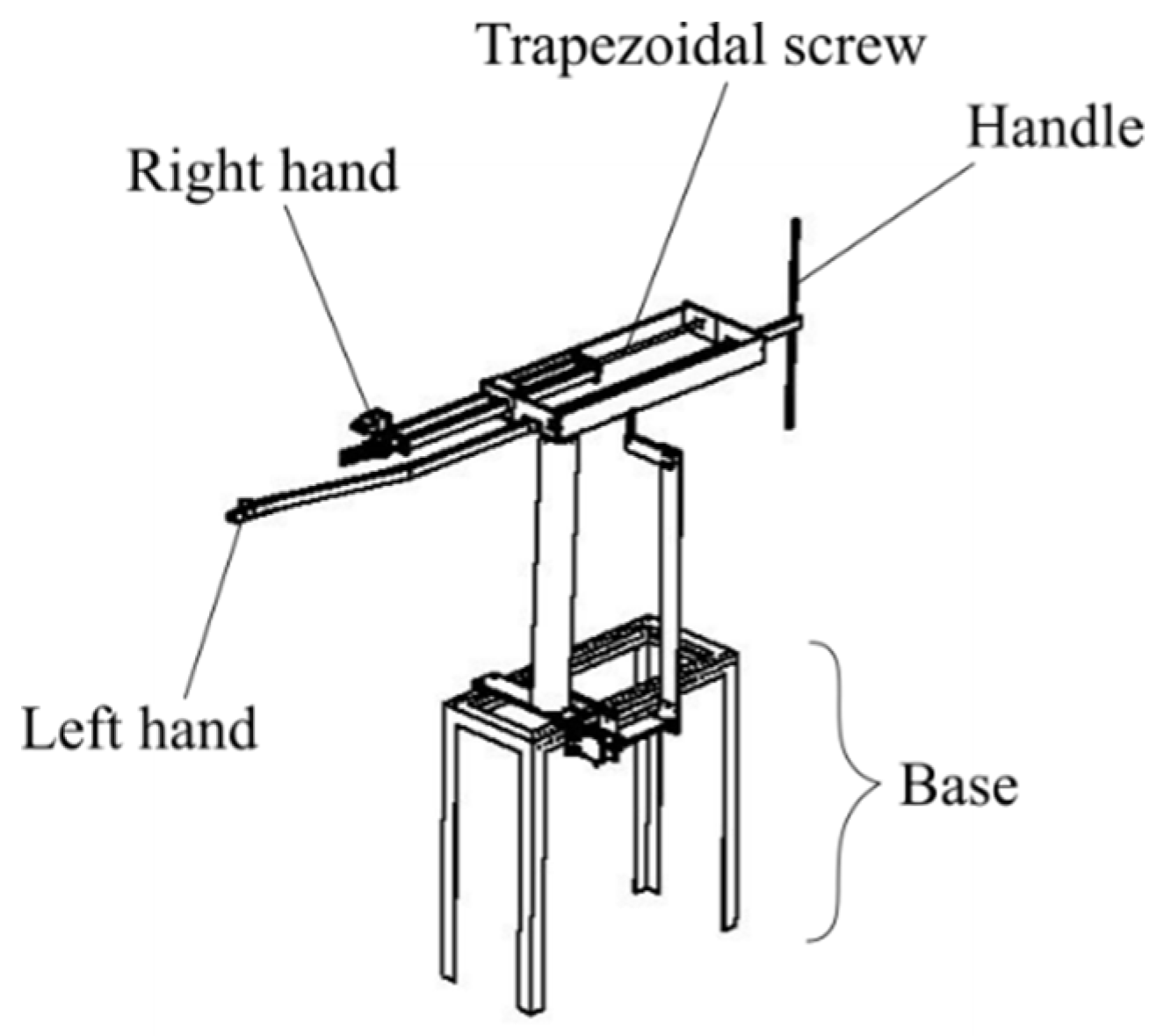
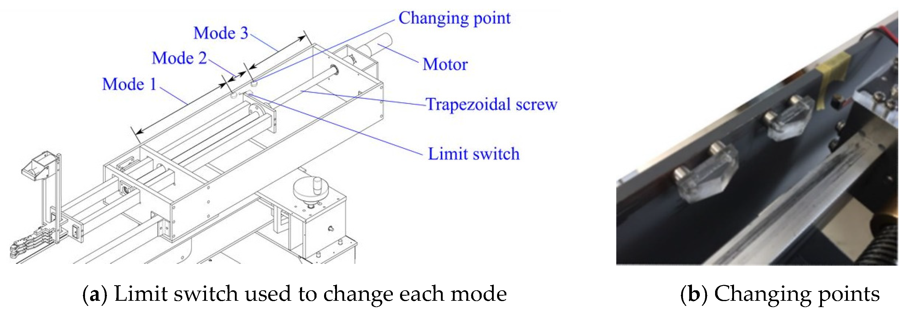
2.2. Driving Part for Drawing a Bowstring

After fitting an arrow to a bowstring, it is drawn by the machine. In machine 1, the movement of the hands caused vibrations in the machine because the mechanism of drawing the bowstring involved rotating a handle attached to the trapezoidal screw. Therefore, in the newly developed machine 2, drawing the bowstring was achieved using a motor (upper right in Figure 2b) instead of a handle to minimize the vibrations.
The motor drive control systems are shown in Figure 3. Motor movements are roughly divided into three modes. Mode 1 includes the rapid drawing of a bowstring, mode 2 involves a deceleration because of being near the clicker and mode 3 involves the tip of the arrow reaching the clicker. Each mode is distinguished by each section in Figure 3a. The changing points of the modes are shown in Figure 3b, and the positions are easily changed. The duty ratio of the motor’s PWM (pulse width modulation) control was set to 30% in mode 1, 12% in mode 2 and 10% in mode 3. The modes are switched by the limit switch shown in Figure 3a. It is switched automatically according to the movement of the arrow and this signal is processed by Raspberry Pi module.
The DC motor (Maxon Motor, model number: 310007) used to draw the bowstring was driven and controlled by an H-bridge circuit containing four power MOSFETs (metal oxide semiconductor field effect transistor) (K100E08N1 and IRF4905). The signals that entered each gate of the MOSFET are PWM signals that were output by the Raspberry Pi module according to the limit switch.

2.3. Left Arm Part for Grasping a Bow

An archer grasps a bow using the left hand, and the bow is completely at rest when aiming at a target. The bow is also at rest for a short moment after the arrow is released. In machine 1, an aluminum square pipe of t 1.5 × 15 × 25 was used but it easily vibrated. As such, we decided to use a thicker pipe to reduce vibration and an iron pipe of t 2 × 20 × 40 was used in machine 2.
The left hand (grip part) of the machine can grasp a bow. In machine 1, the left hand and the bow were not fixed. Therefore, every time an arrow was shot, the bow was released from the left-hand part. In the case of the archers, a grip is performed the same way on each occasion. However, in the case of the machine, grip positions are not the same each time and consequently, the precision of the shot decreases. Therefore, in machine 2, the grip part grasps the bow tightly and protects it by using a polyacetal, as shown in Figure 4a. An image depicting the grasping of the bow is shown in Figure 4b. In addition, the grip part jumps forward from the arm part when the bow is shot.
When the drawing lengths are different, arrows are scattered vertically on the target. Therefore, a sound is generated when the tip of an arrow reaches the clicker position, so that the archers know when to release the arrow. In this machine, the arrows are released when the clicker generates a sound of approximately 1400 Hz for 0.15 s. This sound is acquired by the microphone shown in Figure 4c. The signal flow for the acquisition of the sound by the microphone and transmission to the Raspberry Pi module is shown in Figure 5. The acoustic signal acquired by the microphone is sent to a preamplifier circuit, a CR (capacitor-resistor) low-pass filter, a first-order low-pass filter, a sixth-order high-pass filter, a power-amp, an analog-to-digital converter and then to the Raspberry Pi module. Soon thereafter, the arrow is released.

2.4. Release Mechanism

The image of the right hand is shown in Figure 6a and this is the point at which a bowstring can be hooked. The right hand part of this machine has the same structure of fingers to cause the archers paradox when the arrow is released. Additionally, the bending and stretching of fingers are imitated by pulling wires and springs. The fingers can be locked when they are bent and they can be stretched by sending a current to a solenoid before the arrow is released.
The solenoid is driven by a circuit containing a power MOSFET (SH8M4). The signal from the Raspberry Pi causes the gate of the power MOSFET to be active when this computer module determines that a sound is made by the clicker, as shown in Figure 6b.

3. Results for the Experiment Using Machine 2

3.1. How to Experiment

The shooting machine was moved to the archery range and an experiment was conducted to evaluate the shooting accuracy of the device. This experiment was conducted at approximately 4:00 p.m. on Wednesday, October 2 2019, which was not very windy. The bow that was used was the α -EX made by Yamaha. The arrow was set to be released at the moment when the draw length reached 382 mm. At that length, the weight required to pull the bowstring was 18 kg (40 lb).
The device was placed 70 m away from the target and six arrows were released. These arrows included two flawed arrows. One was always on the right position of the target and the other, which had a missing feather, was always on the down position. The horizontal distance x and vertical distance y were measured from the center of the target to the impact points of the six arrows. The experiments were conducted in two cases, for which the clicker sound was used and was not used as the shooting signal.

3.2. Results of the Experiment

The purpose of this shooting experiment was to evaluate the degree of variation that occurred when the same arrow was released under the same conditions. Therefore, aiming was not the objective. Hence, the origin of the figure in this section represents the average position that the arrows hit.

3.2.1. Evaluation of the Shooting Accuracy of the Device

As a reference, Figure 7a shows the results of an experiment using shooting machine 1 from a previous study [7]. In this experiment, an arrow was shot 10 times at 18 m away from the device using the same arrow. The weight to pull the bowstring was 9 kg (20 lb). The experiment was not conducted 70 m away from the target because the power of the bow was too low to reach the target. Figure 7b,c shows the result obtained using a normal arrow for machine 2. Figure 7b shows the position obtained when the clicker sound was not used as a release signal, and Figure 7c shows the result obtained using the clicker sound. In addition, the standard deviation σ of the distance from the arrows to the center of the target was determined, and a circle was drawn with a radius equal to this value to investigate the variation of the position for the arrows.
As shown in Figure 7c, it was confirmed that the accuracy of shooting is extremely high when the clicker sound was used in shooting machine 2. The target 10-point area had a diameter of 122 mm and 10 arrows could be shot into this area using shooting machine 2 on a non-windy day.

3.2.2. Selection of an Abnormal Arrow

Figure 8 shows the six positions that the arrows hit, including the two abnormal arrows. The abnormal arrows were determined statistically and they were treated as outliers. Then, the outliers can be identified using methods like standard deviation, the Smirnov–Grubbs test and the Thompson test. In this case, the distribution of the normal arrows is known from the experiment, therefore the outliers are detected using the standard deviation of the normal arrows. In this figure, the red circle is drawn with a radius equal to the standard deviation (σ) and a green circle is drawn with a radius of twice the standard deviation (2σ). In general, it is known that 68% of the values were in the σ range and 95% were in the 2σ range. Whether the clicker sound was used or not, the normal four arrows are inside the green circle and the abnormal arrows are outside. Therefore, shooting machine 2 can potentially be used to select arrows.

4. Conclusions

In this study, machine 2 was developed to evaluate its reliability in terms of the selection of arrows via shooting experiments conducted at the archery range at Osaka City University. It was determined that the shooting accuracy of this machine is sufficient to facilitate the selection of arrows if the device is 70 m away from the target and it is not windy. In addition, shooting experiments involving abnormal arrows were conducted. As a result, it was determined that it is possible to identify and exclude these arrows. In particular, if the clicker sound is used, the device allows normal arrows to be distinguished from flawed arrows more clearly.

Acknowledgments

We would like to thank Editage (www.editage.com) for English language editing.

References

  1. Wakatabe, J.; Kanamori, C.; Ando, R.; Matsumoto, T.; Miyazaki, T. Development of Archery Robot: Long-range shooting test using roll angle adjustable bow grasping unit and quasi-static finger release unit. In Proceedings of the 2016 JSME Conference on Robotics and Mechatronics, Yokohama, Japan, 8–11 June 2016. [Google Scholar]
  2. Miyazaki, T.; Mukaiyama, K.; Komori, Y.; Okawa, K.; Taguchi, S.; Sugiura, H. Aerodynamic properties of an archery arrow. Sports Eng. 2013, 16, 43–54. [Google Scholar] [CrossRef]
  3. Kormushev, P.; Calinon, S.; Saegusa, R.; Metta, G. Learning the skill of archery by a humanoid robot iCub. In Proceedings of the IEEE-RAS International Conference on Humanoid Robots, Nashville, TN, USA, 6–8 December 2010. [Google Scholar]
  4. Spot-Hogg Hooter Shooter Bow Tuning Machine. Available online: https://www.abbeyarchery.com.au/p/SHHS/Spot-Hogg+Hooter+Shooter+Bow+Tuning+Machine.html (accessed on 20 February 2020).
  5. Coop’s Bowsmith Pro. Available online: https://www.lancasterarchery.com/coop-s-bowsmith-pro.html (accessed on 20 February 2020).
  6. Kooi, B.W.; Sparenberg, J.A. On the mechanics of the arrow: Archer’s Paradox. J. Eng. Math. 1997, 31, 285–303. [Google Scholar] [CrossRef]
  7. Nakamura, T.; Takada, Y.; Watanabe, H. Statics investigation about archery robot in drawing a bow. In Proceedings of the 2019 JSME Conference on Robotics and Mechatronics, Hiroshima, Japan, 5–8 June 2019. [Google Scholar]
Figure 1. Shooting machine 1 [7].
Proceedings 49 00115 g001
Figure 2. Shooting machine 2.
Proceedings 49 00115 g002
Figure 3. System used to draw a bowstring.
Proceedings 49 00115 g003
Figure 4. Left hand.
Proceedings 49 00115 g004
Figure 5. Flow of the acoustic signal from the microphone to a small PC (Raspberry Pi 3B).
Proceedings 49 00115 g005
Figure 6. Right hand.
Proceedings 49 00115 g006
Figure 7. Test shooting results.
Proceedings 49 00115 g007
Figure 8. Test shooting results including faulty arrows.
Proceedings 49 00115 g008
Table 1. Comparison of shooting machine 1 and 2.
LengthWidthHightMass
Machine 11785 mm399 mm1575 mm24.1 kg
Machine 21872 mm903 mm1607 mm114.4 kg
Publisher’s Note: MDPI stays neutral with regard to jurisdictional claims in published maps and institutional affiliations.

