Proceeding Paper

Measurement of Flight Dynamics of a Frisbee Using a Triaxial MEMS Gyroscope †

Smart Products Engineering Program, Centre for Design Innovation, Swinburne University of Technology, Melbourne 3122, Australia
*
Author to whom correspondence should be addressed.
Presented at the 13th Conference of the International Sports Engineering Association, Online, 22–26 June 2020.
Proceedings 2020, 49(1), 66; https://doi.org/10.3390/proceedings2020049066
Published: 15 June 2020

Abstract

:
A Frisbee with a mass of 0.21 kg, diameter of 0.27 m and moment of inertia (MOI) of 0.002 kg·m2 was instrumented with a triaxial gyroscope. The Frisbee was thrown at low angular velocities as the measurement limit of a single gyroscope was at 6.065 rps. The angular velocities of the triaxial gyroscope were analysed to study the attitude of a Frisbee before and after release. The angular velocities measured were post-processed and the following data were obtained: spin rate at release—3.9–6.14 rps; user-induced peak torque—0.483–0.9 Nm, and peak angular acceleration—204–358 rad/s2; and power input 7.53–19.56 W. The Frisbee wobbled at release which decreased during the flight due to a damping effect. This affected the spin decay, the reduction of wobble lead to a reduced drag force and thus to a smaller spin decay, which was initially 1.12–0.31 rev/s2 and then asymptoted to 0.11–0.01 rev/s2.

1. Introduction

A Frisbee, also called a flying disc, is a sporting instrument used in popular disc throwing games that has been around since the invention of the disc by Fred Morrison in the 1950s [1]. These games are currently growing sports, used by millions of people around the world as a recreational tool and in different sport events such as Disc Golf and Ultimate Frisbee [2]. In Ultimate Frisbee, athletes need to throw the disc to their teammates with high accuracy so that they are able to catch it easily under the pressure of an opponent player within close proximity. A previous study [3] that modelled the flight of a Frisbee showed that when throwing a Frisbee, players try to deliver the disc with the least wobble or without “any components of angular velocity about the X- and Y-axes” or achieving minimal precession (as zero precession is impossible due to nose-up pitching moment). Keeping the precession of a flying disc down to a minimum is critical for achieving a better throw. Other related studies investigating the biomechanics, gyro-dynamics and aerodynamics of a flying disc, used various approaches such as wind tunnels [4,5], computer simulations [1,3], theoretical mathematical models [6] and high-speed cameras [2,7]. A less common approach to study the behaviour of the Frisbee during flight involves using a sensor-based measurement system or inertial measurement unit (IMU). Lorenz [8] calculated the motion attitude of the Frisbee using on-board miniaturized accelerometers and a microcontroller data acquisition system. The study concluded that in almost 50% of cases, the last 0.1 s before release creates the highest launch speed and spin of the Frisbee. Another sensor-based study by Koyanagi et al. [9] estimated the angular velocity of the flying disc by using a disc-mounted triaxial accelerometer. This paper refers to the need for using gyroscope sensors in future studies in order to quantify the precession of the angular velocity vector and related parameters of the Frisbee during flight. The aim of this study is to analyse a wobbling Frisbee during flight using a Frisbee instrumented with a triaxial gyroscope.

2. Materials and Methods

A Frisbee with a mass of 0.21 kg, diameter of 0.27 m and moment of inertia (MOI) of approximately 0.002 kg·m2 was instrumented with an IMU (3-Space Data Logger, Yost Labs, OH, USA). The IMU was attached with double-sided adhesive tape to the underside and as close to the centre of mass of the Frisbee as possible, which was the same sensor placement method used previously by Lorenz [8]. The dimensions of the attached IMU was 57 × 35 × 10 mm, and its mass was 28 g. The triaxial gyroscope’s X-axis was perpendicular to the plane of the Frisbee, and the Y- and Z-axes parallel to the plane. The IMU did not exceed the height of the Frisbee to keep the interference drag to a minimum. For the data analysis, the IMU’s MOI was ignored as it amounted to only 0.05% of the Frisbee’s total MOI. Three angular velocities about the axes of the sensor’s coordinate system were recorded at 95 Hz. The tests were conducted indoors under still air conditions, and the data from 4 throws were analysed. The Frisbee was thrown at angular velocities smaller than the measurement limit of the triaxial gyroscope. The gyro data were recorded onto a secure digital (SD) card and subsequently, the data were analysed with a bespoke software which generated the performance parameters as a function of time [10,11,12,13]. The same data analysis was also used in previous studies of a smart Australian football league (AFL) ball [14,15]. The following parameters were calculated using the software [10,11,12,13] from the gyroscope’s data: peak angular velocity (spin rate), spin rate decay, peak angular acceleration, peak torque, peak power, and wobble (pitch angle of spin axis).

3. Results

The spin rate of a wobbling Frisbee is shown in Figure 1. The spin rate decreased during flight. The angular velocity components (ωy and ωz) parallel to the plane of the Frisbee indicate wobble, represented by damped attitude oscillation seen from ωy and ωz (Figure 1).
Figure 2 shows the precessing spin axis from top-view (clockwise rotation, thrown by a righthander). The spin axis, tilted at release, becomes more and more perpendicular to the plane of the frisbee over time. The spin rate at release ranged from 3.9 to 6.14 rev/s.
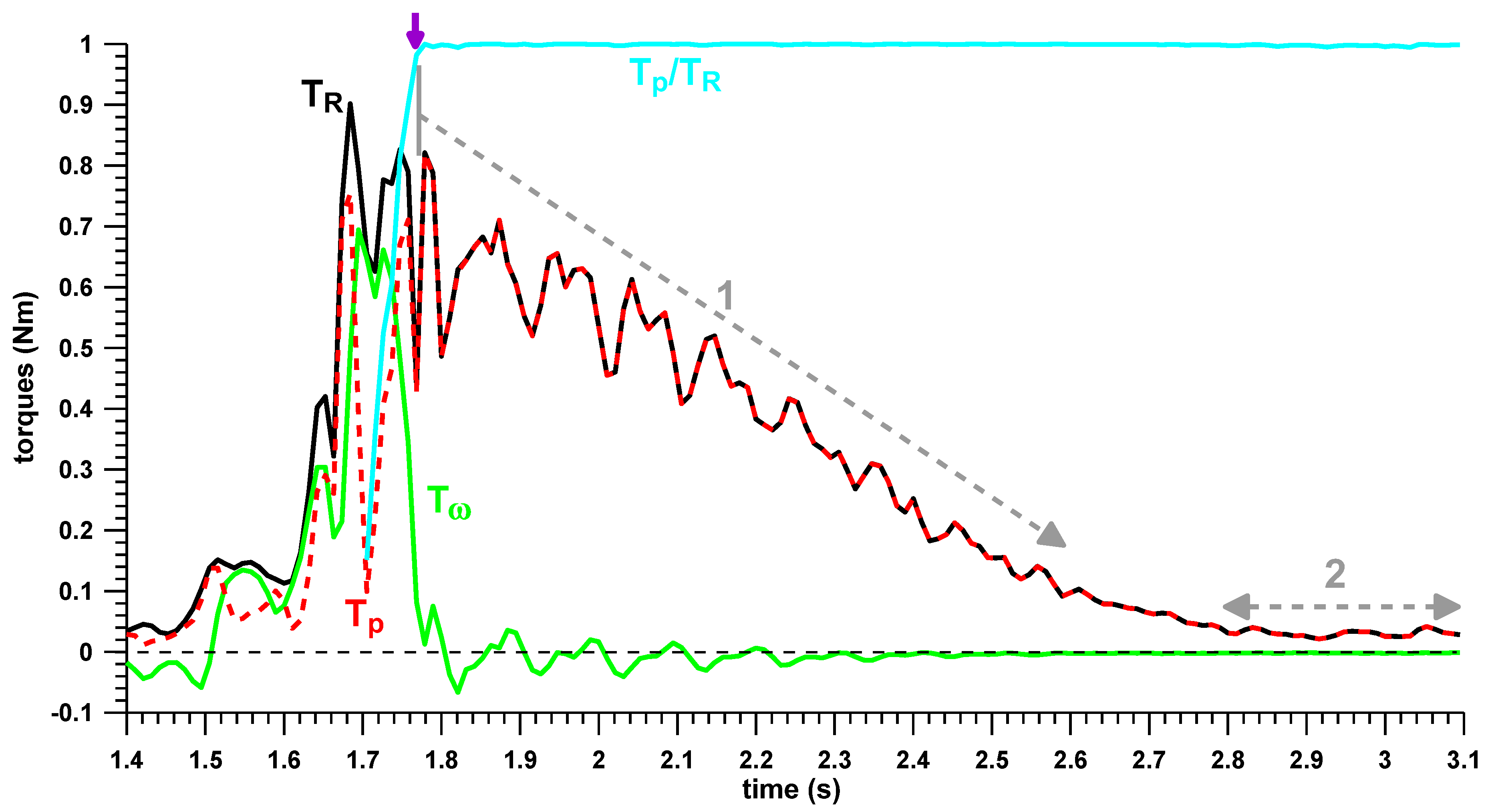
Figure 3 shows the behaviour of the torques acting on the Frisbee, before and after release. Shortly before release, a torque spike TR indicates that the Frisbee is angularly accelerated manually. The peak TR ranged from 0.483 to 0.9 Nm. One component of TR, namely the spin torque Tω, increases the spin rate, and the other component, the precession torque Tp, changes the direction and position of the spin axis. In a perfect throw without wobble after release, Tp should be 0 before release.
The point of release is found from the ratio of Tp to TR, which becomes unity at release (Figure 3). At release, Tω decreases to 0, whereas Tp increases due to aerodynamic torques taking over. These aero torque vectors are perpendicular to the spin axis and cause the spin axis to precess and therefore the wobble. The aero torques have the same effect as the gravity torques in a spinning top. The aero torques decrease over time (Figure 3) until they reach a steady-state, which indicates that the Frisbee is stabilized. The steady-state aero-torques found in the four throws shown in Figure 2 were: 0.068, 0.078, 0.041, and 0.030 Nm.
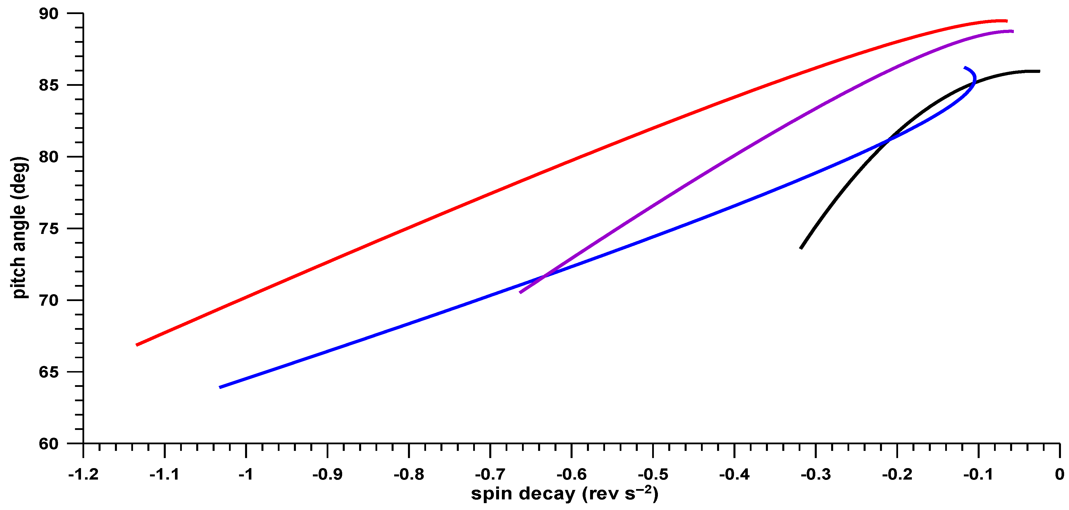
Figure 4 explains the non-linear effect of the spin decay. Immediately after release, the decay is faster (decay rates exceeding 1 revolution per second squared were measured; see Figure 4). The spin decay approaches 0 once a steady state is reached, and the pitch angle of the spin axis reaches 90°. The pitch angle (or elevation angle) is the Euler angle between the plane of the Frisbee and the spin axis. The smallest pitch angle at release was 64° (between 64° and 73°; see Figure 4), and the greatest at the end of the flight was 89.5° (between 86° and 89.5°; see Figure 4).

4. Discussion

The goal of this study was to investigate a wobbling Frisbee during flight using a Frisbee instrumented with a gyroscope. The main findings show that over the course of its flight, the Frisbee reduced its wobbling similar to a damped vibration. The pitch angle of the spin axis, ideally 90° if the Frisbee does not wobble, was 64°–73° at the point of release and approached 90° asymptotically. This behaviour stands in contrast to a flying oval ball, which shows an increased wobble over time [14]. The reducing wobble affected the spin decay, which was initially 1.12–0.31 rev/s2 and then decreased to 0.11–0.01 rev/s2. A reduction in the wobble leads to a reduced drag force, and subsequently, a lower spin decay. In addition, the aerodynamic torques decreased shortly after 1 s after release (1.8 s–2.8 s), until reaching a steady state—the point at which the Frisbee’s wobble was reduced to a minimum. The wobble cannot be reduced to zero due to the permanent nose-up pitching moment. Shown in Figure 4 are the calculated pitch angles of the spin axis, ranging between 64° and 89.5° from release point until the end of the flight. The current study was one out of few studies using an on-board miniaturized IMU attached to a Frisbee to study in-flight wobbling and related parameters during flight. The method presented in this study was successful for investigating a low spin wobbling Frisbee during flight as well as being cost effective and with a simple set-up. Future work will focus on using the same instrumentation approach but will employ better performance sensors, namely high-speed IMU’s to measure higher velocity disc deliveries. Studying the gyroscopic effect of a flying Frisbee via our approach may be useful in the future to critically analyse other flying discs flight patterns, and for training purposes to improve the throwing consistency and other related performance parameters.

Funding

No funds were received for conducting this study, nor for covering the costs to publish in open access.

Conflicts of Interest

The author declares no conflict of interest.

References

  1. Baumback, K. The Aerodynamics of Frisbee Flight. Undergrad. J. Math. Model. One Two 2010, 3. [Google Scholar] [CrossRef]
  2. Hubbard, M.; Hummel, S.A. Simulation of Frisbee flight. In Proceedings of the 5th Conference on Mathematics and Computers in Sport, University of Technology, Sydney, Australasia, 14–16 June 2000; pp. 124–134. [Google Scholar]
  3. Hummel, S.A. Frisbee Flight Simulation and Throw Biomechanics. Master’s Thesis, University of California, Davis, CA, USA, July 2003. [Google Scholar]
  4. Nakamura, Y.; Fukamachi, N. Visualization of the Flow Past a Frisbee. Fluid Dyn. Res. 1991, 7, 31–35. [Google Scholar] [CrossRef]
  5. Potts, J.R.; Crowther, W.J. Visualisation of the Flow Over a Disc-wing. In Proceedings of the Ninth International Symposium on Flow Visualization, Edinburgh, Scotland, UK, 22–25 August 2000. [Google Scholar]
  6. Koyanagi, R.; Seo, K.; Ohta, K.; Ohgi, Y. A Computer Simulation of the Flying Disc Based on the Wind Tunnel Test Data. Procedia Eng. 2012, 34, 80–85. [Google Scholar] [CrossRef]
  7. Hummel, S.; Hubbard, M. Identification of Frisbee Aerodynamic Coefficients Using flight data. In Proceedings of the 4th International Conference on the Engineering of Sport, Kyoto, Japan, 3–6 September 2002; Volume 20. [Google Scholar]
  8. Lorenz, R.D. Flight and Attitude Dynamics Measurements of an Instrumented Frisbee. Meas. Sci. Technol. 2005, 16, 738. [Google Scholar] [CrossRef]
  9. Koyanagi, R.; Ohgi, Y. Measurement of Kinematics of a Flying Disc Using an Accelerometer. Procedia Eng. 2010, 2, 3411–3416. [Google Scholar] [CrossRef]
  10. Fuss, F.K.; Doljin, B.; Ferdinands, R.E.D.; Beach, A. Dynamics of spin bowling: The normalized precession of the spin axis analysed with a smart cricket ball. Proc. Eng. 2015, 112, 196–201. [Google Scholar] [CrossRef]
  11. Doljin, B.; Fuss, F.K. Development of a smart cricket ball for advanced performance analysis of bowling. Proc. Technol. 2015, 20, 133–137. [Google Scholar] [CrossRef]
  12. Fuss, F.K.; Doljin, B.; Ferdinands, R.E.D. Effect of the grip angle on off-spin bowling performance parameters, analysed with a smart cricket ball. Proceedings 2018, 2, 204. [Google Scholar] [CrossRef]
  13. Fuss, F.K.; Doljin, B.; Ferdinands, R.E.D. Effect on Bowling Performance Parameters When Intentionally Increasing the Spin Rate, Analysed with a Smart Cricket Ball. Proceedings 2018, 26, 226. [Google Scholar] [CrossRef]
  14. Fuss, F.K.; Smith, M.R. Development of a smart oval ball for assessment of angular flight dynamics and precision of kick execution. Sports Technol. 2011, 4, 151–158. [Google Scholar] [CrossRef]
  15. Fuss, F.K.; Smith, M.R.; Leali, F. Kick Precision and Spin Rate in Drop and Torpedo Punts. Procedia Eng. 2013, 60, 448–452. [Google Scholar] [CrossRef]
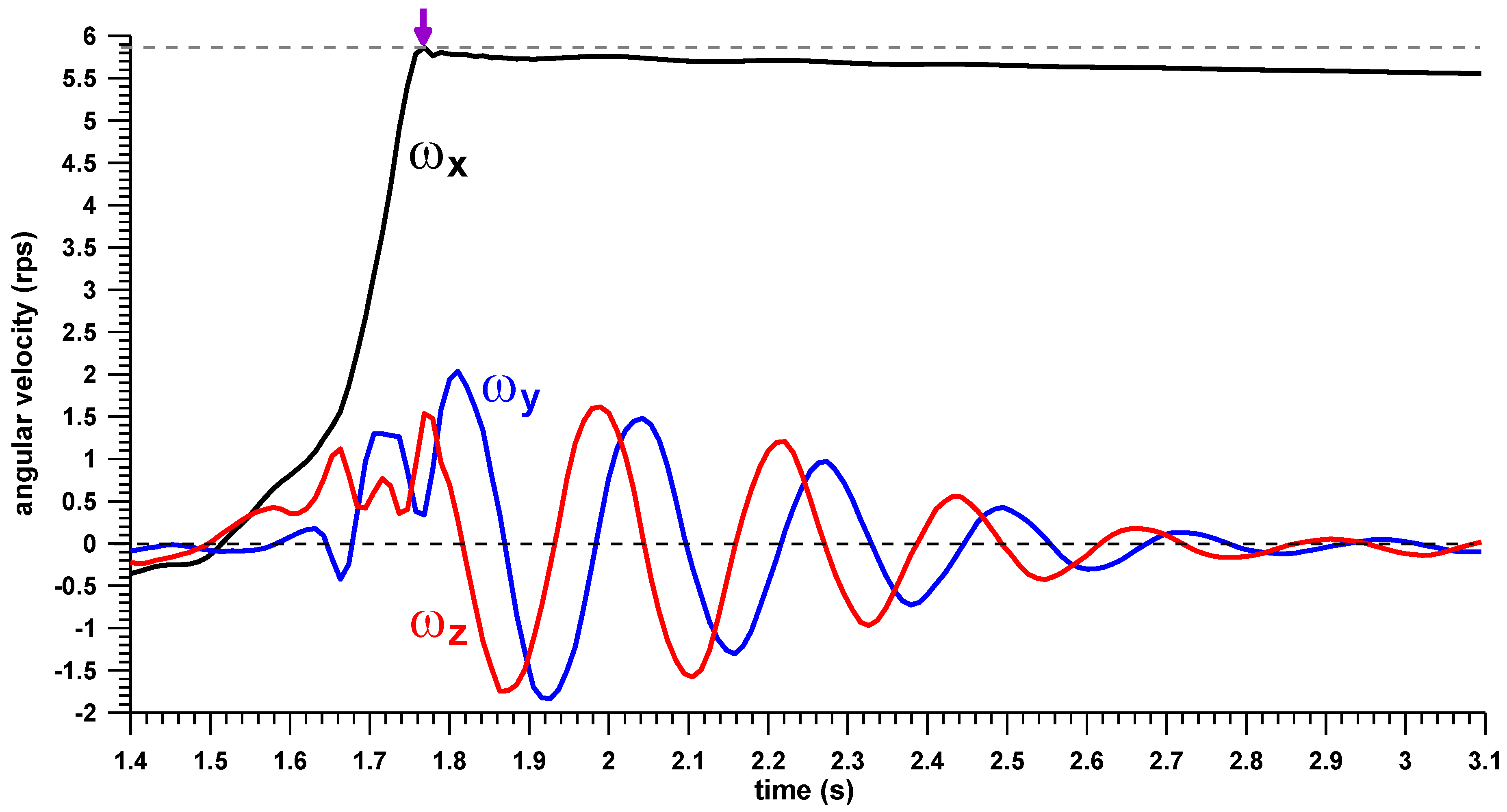
Figure 1. Angular velocity (ω) components of the Frisbee against time; the x-component is perpendicular to the plane of the Frisbee; the release point is indicated by a small purple arrow at approximately 1.75 s.
Proceedings 49 00066 g001
Figure 2. z-component of the angular velocity (ωz) unit vector against the y-component (ωy) unit vector projected on the plane of the Frisbee, i.e., yz plane), of the flight phases of 4 different Frisbee throws; the outermost starting point is the release point of the Frisbee.
Proceedings 49 00066 g002
Figure 3. Torques acting on the Frisbee against time; TR = resultant torque, Tω = spin torque (that changes the magnitude of the spin rate), Tp = precession torque (that moves the spin axis with respect to the solid Frisbee); the release point (small purple arrow) is identified by Tp = TR and Tp/TR = unity; ‘1′ = transient aerodynamic torques (decreasing); ‘2′ = steady-state aerodynamic torques.
Proceedings 49 00066 g003
Figure 4. Pitch angle of the spin axis (angular velocity vector) against the spin decay of the 4 Frisbee throws shown in Figure 2 (same colour coding).
Proceedings 49 00066 g004
Publisher’s Note: MDPI stays neutral with regard to jurisdictional claims in published maps and institutional affiliations.