Proceeding Paper

External Wall Technological Solutions for Carbon Zero Schools in Italy †

Department of Civil and Environmental Engineering, University of Florence, 50139 Florence, Italy
*
Author to whom correspondence should be addressed.
Presented at the 9th Innovations-Sustainability-Modernity-Openness Conference (ISMO’20), Bialystok, Poland, 20–21 May 2020.
Proceedings 2020, 51(1), 13; https://doi.org/10.3390/proceedings2020051013
Published: 16 July 2020

Abstract

:
For the construction of a carbon zero school building, it is necessary to choose a proper technological solution for the external wall in the early stages of the design process. At the same time, the material to be used for the insulation layer must be defined. The main aim of the presented study is to analyze five different technological solutions for the external wall combined with four different materials for the insulation layer. The solutions will be used in a new typological model for kindergarten and analyzed and compared with respect to both environmental impact and energy performance.

1. Introduction

The choice of the technological solution for the external envelope is one of the passive strategies that necessarily influences the energy performance of a building, as it regulates the energy flow between the inside and outside. In literature, the studies concerning the technological solution to be utilized for the external wall mainly concern the evaluation of the dynamic thermal properties of the material typology used for the insulation layer and its thickness. The optimization of the insulation thickness is performed by evaluating different features separately or simultaneously: energy one, environmental one, and economic one. Consequently, the following parameters are usually considered: the energy needs for heating and cooling, respectively (kWh/m2a) [1,2,3], the global warming power for the evaluation of CO2 emissions (kgCO2/m2a) [1,2,4], the total cost (the sum of energy cost, insulation material cost, and the cost in terms of CO2) [1,4] related to the payback period [5]. The main aim of the presented study is to analyze and compare five different technological solutions for the external wall with five different typologies of load bearing layer combined with four different load bearing structures (reinforced concrete, steel, platform frame, and cross laminated timber (XLAM)) and considering four different materials for the external insulation layer (wood fiber, sintered expanded polystyrene, rock wool, and glass wool).

2. Method and Input Data

The minimum thickness of insulation to be used for the five different technological solutions was initially defined in order to comply with the minimum thermal transmittance (U measured in W/m2K) required for the reference building [6]. Then, the dynamic thermal properties of the external wall were calculated and, according to the four different materials considered for the insulation layer, the thickness of the insulation was increased or kept the same in order to obtain a periodic thermal transmittance (YIE measured in W/m2K) less than 0.10 W/m2K, as required by current energy regulation, and a time shift (φ measured in hours) possibly equal to 8 h. Later, a parametric analysis was carried out by varying—with a step of 0.02 m—the thickness of each insulation typology for each technological solution for the external wall in a range within the minimum required by the regulation and a maximum of 0.24 m, considered as the maximum thickness achievable from a constructive point of view. For each solution, the energy consumption for heating and cooling (kWh/m2a) was calculated through an energy simulation in dynamic regime with an hourly time step. Finally, the environmental impact was defined in terms of CO2 (kgCO2/m2a) both for the construction and operational phase. For energy simulations, a typological model for kindergarten with a compact shape and internal courtyard was considered. It was developed on a single ground floor (with a gross surface area equal to 1050 m2), with an aspect ratio equal to 0.53 m−1. The energy simulations were carried out with Design Builder, considering the city of Florence located in climate zone D, as Italian regulation establishes. The technological solutions for the external wall, related to suitable structural systems, are the following:
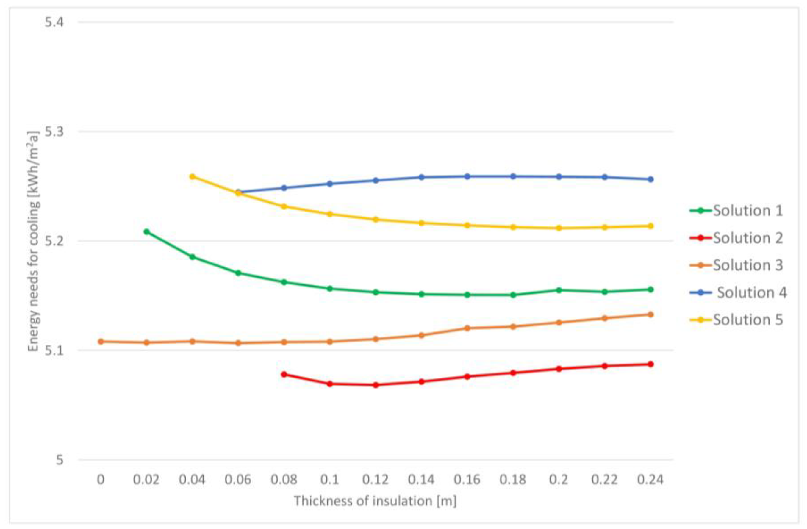
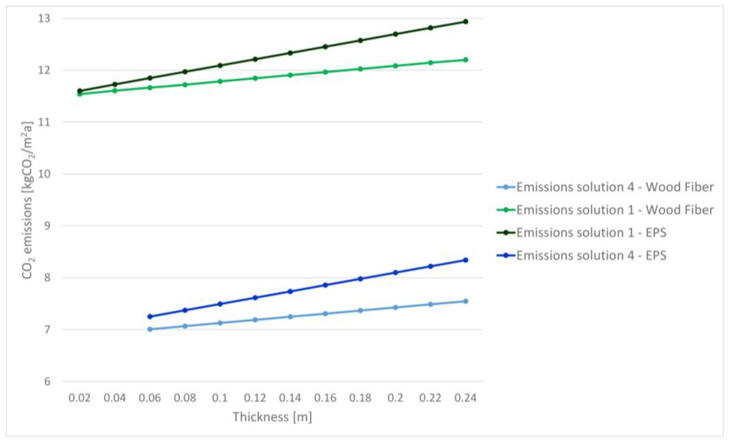
  • Solution 1: reinforced concrete frame structure, with load bearing layer in lightweight bricks (0.30 m), external insulation (0.02 m), and a false wall constituted by a double plasterboard panel (0.015 m) and rock wool insulation layer (0.05) to ensure the right acoustic insulation required by regulation.
  • Solution 2: steel frame structure, external wall made of dry solution with cement board external panel (0.0125 m), waterproofing sheet (0.0018 m), insulation layer (0.08), plasterboard panel (0.015 m), and false wall, as in Solution 1.
  • Solution 3: steel frame structure, load bearing layer in aerated autoclaved concrete blocks (0.30 m), and false wall, as in Solution 1.
  • Solution 4: wooden platform frame structure, external insulation (0.02 m) applied on a single oriented strand board (OSB) (0.02 m), internal insulation layer (0.06), waterproofing sheet (0.0018 m), single OSB panel (0.02 m), and false wall, as in Solution 1.
  • Solution 5: XLAM wooden structure, external insulation applied on XLAM wall (0.04 m), and false wall as in Solution 1.
In the results (Table 1), solutions 1–5 refer to a thickness of insulation equal to the minimum required by regulation, while solutions 1A–5A have a thickness such as to obtain the right dynamic thermal transmittance value and a proper time shift.

3. Results and Discussion

Table 1 shows the dynamic thermal transmittance (YIE measured in W/m2K) and the time shift (φ measured in hours) and the thickness of insulation (t measured in m) of the five technological solutions analyzed with respect to each insulation material considered.
It is possible to notice immediately that the two options (1–5 and 1A–5A) corresponded for most solutions.
It is possible to state that the change of the insulation material mainly affected the solutions that had less mass surface: Solution 2 (60 kg/m3 < Ms < 70 kg/m3) and Solution 4 (107 kg/m3 < Ms < 115 kg/m3). For instance, when using EPS (sintered expanded polystyrene) insulation (density ρ = 35 kg/m3) for Solution 2, 0.32 m are needed to ensure a time shift greater than 8 h. Consequently, for climate zones with particularly hot summers, it is advisable to use a technological solution with high surface mass in order to ensure proper internal comfort conditions, especially during the summer season, or a solution with lower mass surface but combined with an insulation material with higher density: for instance, wood fiber (density ρ = 160 kg/m3). The following graphs (Figure 1 and Figure 2) illustrate the trend of energy needs, respectively, for heating and cooling with respect to the variation of insulation thickness for each technological solution. The trend of consumptions was the same for each insulation material considered, as they were characterized by similar thermal conductivities. In accordance to the literature, the results obtained showed that the variation of the thickness of insulation mainly influenced the energy needs for heating. In addition, the effect on the energy needs was higher for lower insulation thickness (<0.14 m). As for cooling, the increase in insulation did not lead to a significant reduction in energy needs. For the solutions with lower mass surface, the increase in insulation thickness led to a proportional rise in energy needs for cooling (solution 2).
However, the following graph (Figure 3) shows the CO2 emissions trend exclusively due to the construction of the building with respect to the insulation layer variation (wood fiber and EPS) for technological solutions 1 and 4. These were the worst and the best solutions, respectively, when considering the environmental impact. The emissions during the operational phase were null because a heat pump powered by photovoltaic panels installed on the roof was considered for the building, and they met 100% of the electricity energy needs of the building. For both options, the increase in emissions was proportional to the rise in insulation thickness, even if the solutions with EPS were characterized by a greater slope than wood fiber ones. The graph shows that the analyzed technological solutions were characterized by similar environmental impacts. As a matter of fact, the global warming power (GWP) changed within a range of 7 kgCO2 and 11.5 kgCO2, considering the minimum insulation thickness required by current Italian regulation.

4. Conclusions

In conclusion, if the technological solutions for the external walls meet the Italian law requirements in terms of thermal transmittance and dynamic thermal transmittance, it is possible to use each one of the recommended insulation materials that are valid options for the construction of zero emissions schools in Italy indiscriminately. All the analyzed technological solutions for the external wall allow an optimum energy performance to be obtained (primary energy demand equal to about 24 kWh/m2a) and low CO2 emissions for construction (within 7 kgCO2 and 11.5 kgCO2) with the aim of a carbon-free economy by 2050. This is valid for each type of proposed insulation material that ensures a thermal transmittance for the external envelope equal to about 0.28 W/m2K.

Author Contributions

C.C., F.B., and V.D.N. conceived the idea for the paper; C.C. performed the energy simulations; C.C., F.B., and V.D.N. analyzed the data; C.C., F.B., and V.D.N. wrote the paper.

Conflicts of Interest

The authors declare no conflict of interest.

References

  1. Rad, E.A.; Fallahi, E. Optimizing the insulation thickness of external wall by a novel 3E (energy, environmental, economic) method. Constr. Build. Mater. 2019, 205, 196–212. [Google Scholar] [CrossRef]
  2. Agostino, D.D.; De Rossi, F.; Marigliano, M. Evaluation of the optimal thermal insulation thickness for an office building in different climates by means of the basic and modified “cost-optimal” methodology. J. Build. Eng. 2019, 24, 100743. [Google Scholar] [CrossRef]
  3. Fodoup, F.; Vincelas, C.; Ghislain, T. The determination of the most economical combination between external wall and the optimum insulation material in Cameroonian’s buildings. J. Build. Eng. 2017, 9, 155–163. [Google Scholar] [CrossRef]
  4. Zhang, L.; Liu, Z.; Hou, C. Optimization analysis of thermal insulation layer attributes of building envelope exterior wall based on DeST and life cycle economic evaluation. Case Stud. Therm. Eng. 2019, 14, 1–9. [Google Scholar] [CrossRef]
  5. Rosti, B.; Omidvar, A.; Monghasemi, N. Optimal insulation thickness of common classic and modern exterior walls in different climate zones of Iran. J. Build. Eng. 2020, 27, 100954. [Google Scholar] [CrossRef]
  6. Governo Italiano. Decreto Ministeriale del 26 Giugno 2015. Applicazione Delle Metodologie di Calcolo Delle Prestazioni Energetiche e Definizione Delle Prescrizioni e dei Requisiti Minimi Degli Edifici; Governo Italiano: Rome, Italy, 2015. [Google Scholar]
Figure 1. Energy needs for heating for different types of technological solutions.
Proceedings 51 00013 g001
Figure 2. Energy needs for cooling for different types of technological solutions.
Proceedings 51 00013 g002
Figure 3. CO2 emissions of technological solutions 1 and 4.
Proceedings 51 00013 g003
Table 1. Dynamic thermal characteristics of different types of technological solutions.
InsulationWood FiberEPSMineral WoolGlass Wool
SolutionYIEΦtYIEφtYIEφtYIEφt
10.00918.470.020.00918.310.020.00918.360.020.00818.370.02
1A
20.2074.690.080.2162.230.080.2392.800.080.2362.750.08
2A0.0878.140.140.0958.100.320.0588.270.240.0598.080.24
30.01815.89-0.01815.89-0.01815.89-0.01815.89-
3A
40.0511.880.040.1019.190.040.0999.330.040.0999.180.04
4A0.0799.760.06
50.0214.360.040.0213.820.040.0213.940.040.0213.950.04
5A
Publisher’s Note: MDPI stays neutral with regard to jurisdictional claims in published maps and institutional affiliations.

