Proceeding Paper

Exergy Analysis of a Wood Fireplace Coupled with Thermo-Electric Modules †

by
Giampaolo Manfrida
and
Lorenzo Talluri
*
Dipartimento di Ingegneria Industriale, Università degli Studi di Firenze, 50134 Firenze, Italy
*
Author to whom correspondence should be addressed.
Presented at the First World Energies Forum, 14 September–05 October 2020; Available online: https://wef.sciforum.net/.
Proceedings 2020, 58(1), 10; https://doi.org/10.3390/WEF-06920
Published: 11 September 2020
(This article belongs to the Proceedings of The First World Energies Forum—Current and Future Energy Issues)

Abstract

:
In recent years the climate change issue, coupled with the concern of resource depletion, is favoring the blossoming of renewable energy conversion systems. Particularly, the development of new technologies for the combustion of biomass has drawn special attention to the possibility of coupling thermoelectric modules with stove-fireplaces. The current thermoelectric generators have many attractive points, such as a solid structure, absence of noise, and no maintenance required; however, due to their very low efficiency (4–8%), they are still economically non-attractive. However, if the modules are applied to a heat source, which otherwise would be wasted, the interest in the solution certainly grows. In this study, an exergy analysis of a stove-fireplace coupled with thermo-electric modules is performed, with the aim of identifying the critical issues of the overall system. The obtained exergy efficiency of the whole system resulted to be of 36.2%. A sensitivity analysis on the main parameters affecting the second law efficiency of the system (such as number of cells, dimension of the stove fireplace, heat input …) is also carried out.

1. Introduction

In the last years, several solutions for the energy management of small microgrids have been developed. Particularly, smart distributed energy systems [1,2] had a widespread diffusion. The necessity of a smart energy system is due to the need of managing not only one energy demand but numerous, such as electricity, heat, and cold. Connected to the diffusion of smart energy systems are the concerns of environmental pollution and resource depletion, which have favored the blooming of renewable energy.
Among other renewables, biomass fireplaces are extensively used, especially in isolated households, which are not connected to the national natural gas distribution network. In this context, a wood fireplace is used in order to generate the heating, as well as hot sanitary water with the aid of a water storage system.
A further advancement of wood fireplaces could be to use them for the production of not only heat and sanitary water but also electricity. The conditions to implement thermo-electric (TE) power generation systems to the fireplace seem very appealing. Indeed, the size of the combustions chamber is larger when compared to pellet or wood chip stoves; furthermore, there is a very wide area of the fireplace, which operates through radiation heat transfer, allowing a relevant heat flux to the walls of the stove. Furthermore, from the cooling of the TE, sanitary hot water can be generated, increasing therefore the efficiency of the system.
The utilization of TE modules is favored compared to other waste heat energy systems by its low environmental impact, as it avoids all gas emissions [3] thanks to its solid configuration. Moreover, TE modules can be positioned in parallel, allowing great flexibility for the configuration of the system. They also require very limited maintenance and do not have any moving parts or involve chemical reactions to convert heat into electricity.
An interesting study which aimed to prove the technical feasibility of coupling TE modules to small cooking ovens was developed by Champier et al. [4]. In this study, the authors developed an experimental campaign, achieving the power production of 6 W, with 4 TE modules. The modules where air-cooled on the cold side, using a large finned heat dissipater.
A successive work by Champier et al. [5] utilized a hot water storage unit to remove the heat from the TE modules, in order to increase the convective heat flux. In this work, the authors developed a full model of heat transmission across the module, including equations describing the electrical characteristic of the TE module, which showed a good agreement with the experiments that they carried out, obtaining a maximum power output of 10 W.
An experimental investigation on an electric oven test bench was carried out by Zheng et al. [6], in order to validate the developed model of TE. In their study, an economic assessment was also carried out, highlighting the possibility of attacking the market with a 5.6 yrs PBP.
Other numerical and experimental studies on domestic woodstoves fitted with TE modules were carried out by Nuwayhid et al. [7,8]. In these studies, they obtained from the first developed prototype a power production of 1W. The power production was connected to the utilization of low-cost Peltier modules, as well as the low temperature difference, which they achieved.
A higher power output was obtained by Lertsatitthanakorn [9], applying the TE modules on a biomass cooking stove. The reached power output was 2.4 W with a temperature difference of 150 °C, which ensured a short PBP (lower than 1 year), especially when compared to batteries supplying the required power instead of the TE modules.
An experimental campaign on the utilization of TE modules to a domestic natural gas water heater was developed by Ding et al. [10]. In their study, the TE modules generated a maximum power of 42.4 W with the maximum flow rate conditions (33 lpm) with a temperature difference of 80 °C.
The possible application of TE modules to stove-fireplaces was assessed by Sornek et al. [11]. They developed an experimental test rig, in which they compared to types of TE modules with 2 different operating ΔT. They concluded that the maximum possible power generation would be of 30 W, while achieving an experimental value of 6 W, stating that the solution would not be therefore economically profitable. In a successive work [12], they compared 2 types of TE modules with different cooling systems. The maximum experimental obtained power for the first assessed TE modules was 18.8 W, corresponding to 41.7% of the nominal power output. The maximum power output obtained by the second type was higher (31.2 W), but with a 31.2% relative value with respect to the nominal power output.
From the literature review, it seems that the majority of the developed works were aimed to demonstrate the practical operation of a thermo electric system integrated with a stove, adding commercial TE modules to existing stoves with minor adjustments. This leads to very low power levels, mainly because of limits determined by the air cooling of the backside of the modules or of the limited temperature difference and heat flux.
The authors, in a previous study [13], proposed to apply TE modules to a wood fireplace, taking advantage of the high heat flux available in the radiation chamber. It was demonstrated that 7 modules of 20 W could be applied to a 26 kWt fireplace generating therefore a total power output of 140 W. The aim of the current study is to develop an exergy analysis in order to assess the sources of the inefficiency of the system. Indeed, it seems that there is still a gap in the literature regarding the exergy analysis of wood fireplaces. The main sources of exergy destruction and loss are therefore highlighted in this study.

2. Materials and Methods

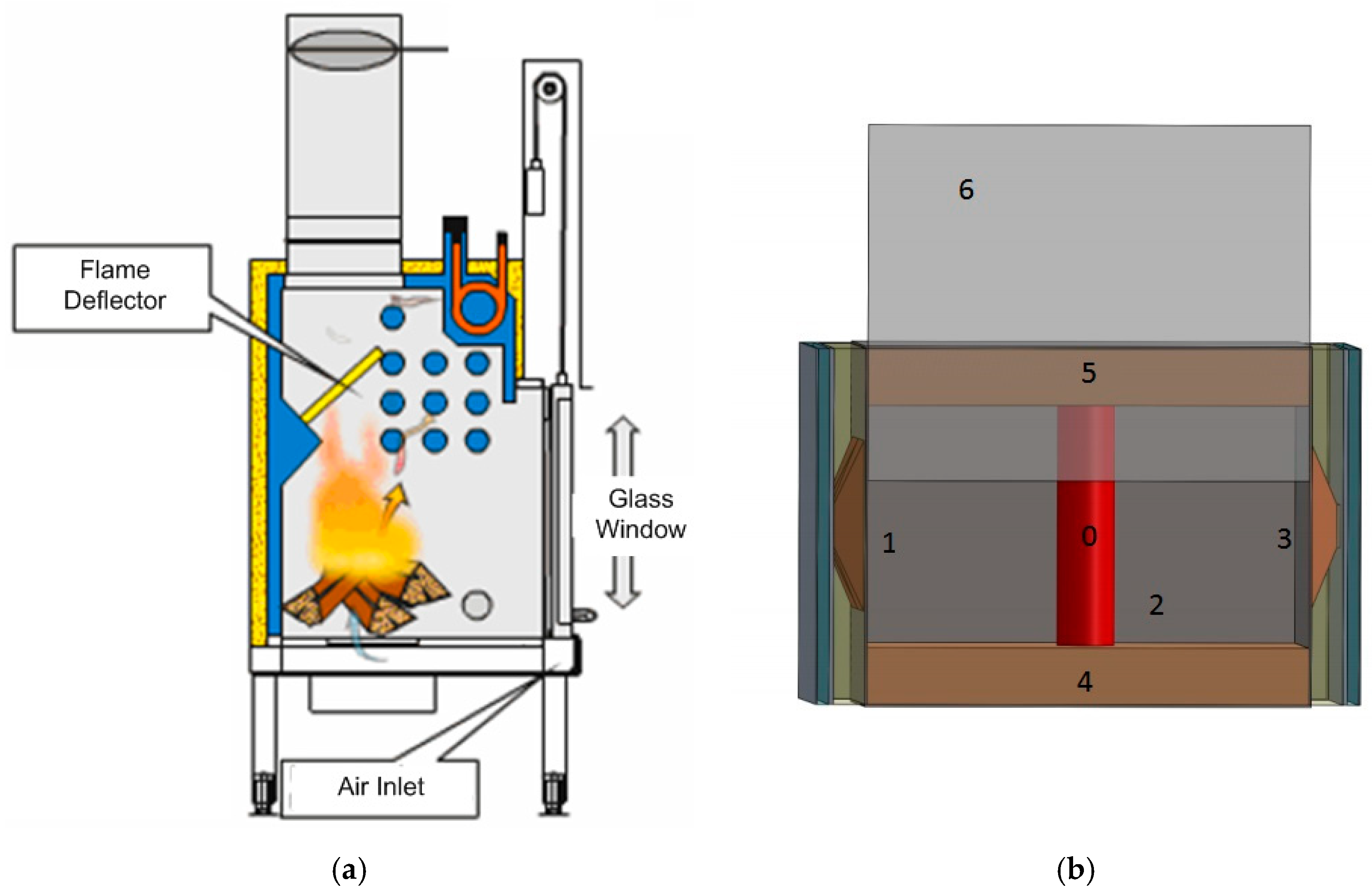
2.1. Layout of the Fireplace Unit

In order to comply with the heating demand of a typical household, a wood fireplace with a maximum power rating of 26 kWt is required. To cover the production of sanitary water, a hot water storage of about 0.4 m3 is required, which impacts on the dimensions of the fireplace. The water storage is heated through multi-pass fire-tube configurations, which allow reaching typical temperatures for sanitary water and heating system in the range of 60–80 °C. Table 1 presents the overall dimensions of the analyzed wood fireplace (Figure 1 for a general schematic), with a focus on the combustion chamber. The side and back walls of this last (1, 2, 3) are made by CORTEN steel; the upper and lower sides (4, 5) have a silica-based refractory liner having low emissivity, while front windows to the ambient is made of quartz glass (6). The side and back faces are equipped with TE modules. In order to properly convey the high-flux radiative heat transfer to the TE section, it is necessary to use a Heat Flux Concentrator (HFC). The HFC is made of copper and packaged inside an insulated box, hosting inside also the TE module and the water cooler (for removing heat from the TE), as displayed in Figure 1. The void space between the HFC and the box is filled with fine refractory sand, so that heat is preferably transmitted through the high-conductivity copper thermal bridge. Externally to the HFC box, still air is considered to fill the gap between the CORTEN and the outside ambient. Figure 2 shows the schematic of the wood fireplace with hot water storage and of the combustion chamber with HFC.

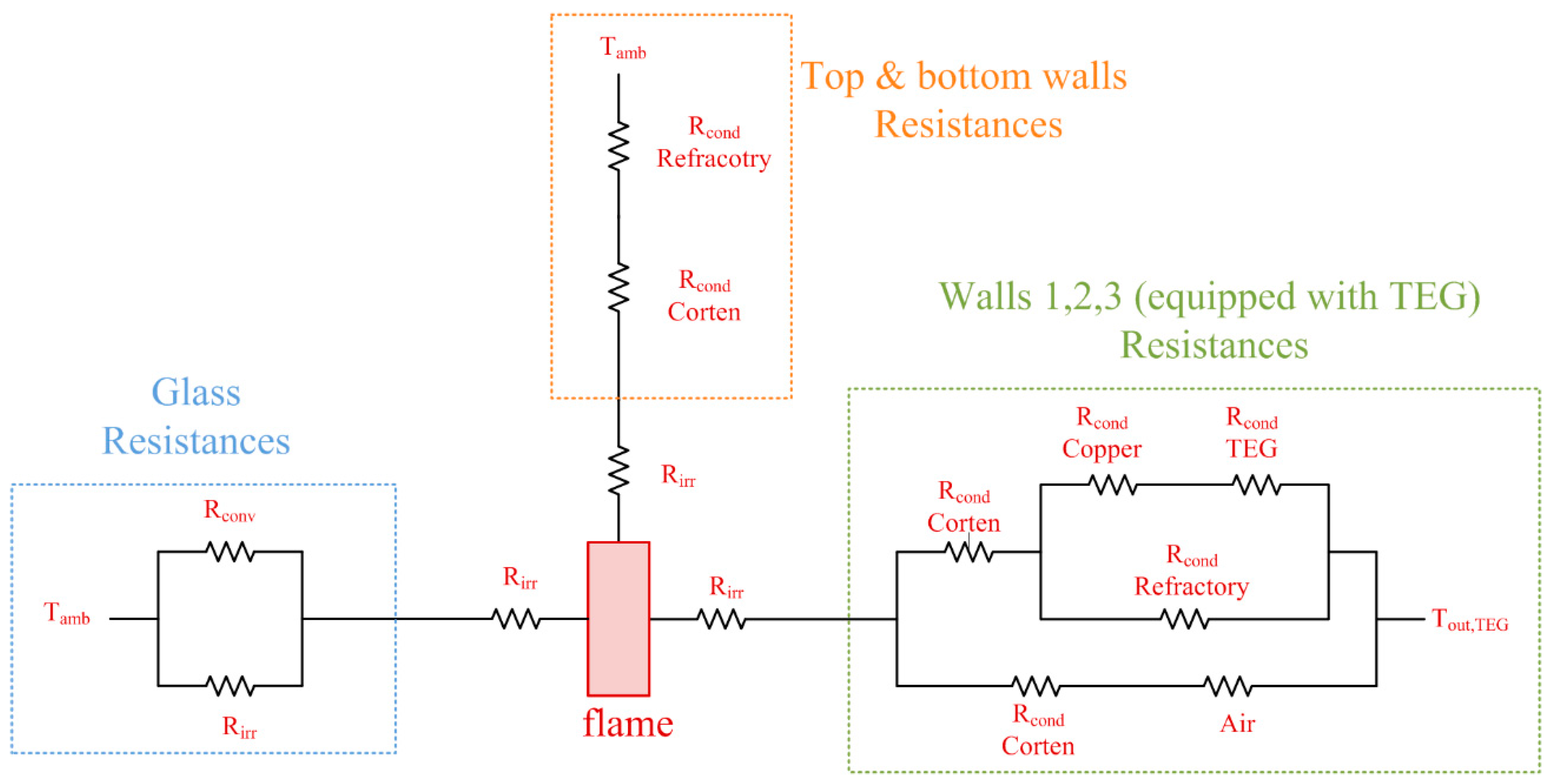
2.2. Thermodynamic and Exergy Model of the Thermo-Electric Fireplace

The model of the thermo-Electric fireplace [13] was developed through several coupled sections:
  • Radiation model of the combustion chamber;
  • Wavelength selectivity of the glass window;
  • Heat transfer to thermo-electric modules (in/out);
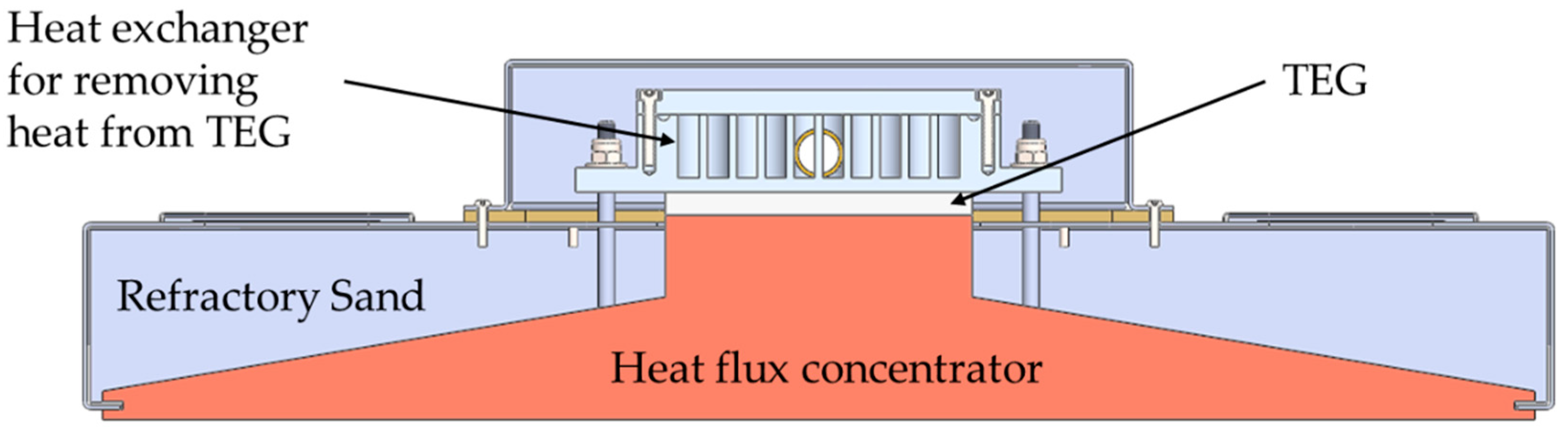
  • Heat flux concentrator.
The fundamental equations are detailed in Appendix A and Appendix B. Furthermore, Figure 3 displays the equivalent thermal resistance network for the thermo-electric wood fireplace.
The exergy analysis combines the First and Second Laws of Thermodynamics, allowing the evaluation of the efficiency of the energy system and the irreversibilities (exergy destructions) of the system components [14,15].
Exergy is generally defined as the maximum work obtainable from a system or a process through the interaction with the surrounding environment. Having to deal with heat fluxes, it is convenient to apply a heat-exergy approach. Therefore, the heat exergy can be determined [16] defining a Carnot factor, which determines the quality of the heat depending on its temperature, as in Equation (1):
Ex ˙ j = θ k · Q k ˙ = ( 1 T a T k ) · Q k ˙
Every layer of the system can be described by an exergy balance distinguishing between exergy rates connected with its fuel and product [16], according to the component exergy balance:
Ex ˙ F , k = Ex ˙ P , k + Ex ˙ D , k + Ex ˙ L , k
Equation (2) takes into account the exergy destructions and losses, which influence the irreversibility of the system operation. An exergy destruction derives from friction or irreversibility of heat transfer within a defined control volume, while an exergy loss is associated with exergy transfer (waste) to the surroundings. The directly calculated exergy efficiency of a component is defined as the ratio between the product exergy and the fuel exergy. The indirect definition of exergy efficiency requires the evaluation of exergy destructions and losses. The exergy efficiency can be determined by the following Equation (3):
η k = Ex ˙ P ; k Ex ˙ F ; k = 1 Ex ˙ D ; k + Ex ˙ L ; k Ex ˙ F ; k
which can be applied both at each layer and at system level.
In the present case, all the grouped systems (glass, bottom-and top walls, and walls enclosing the TEGs) are producing exergy loss to the environment.

3. Results

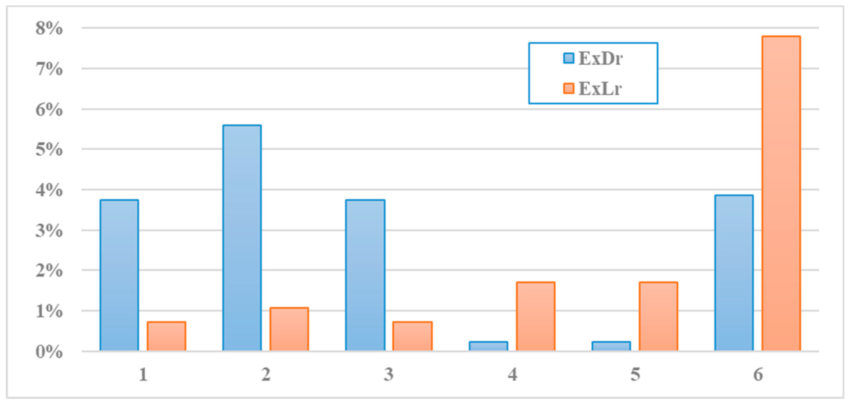
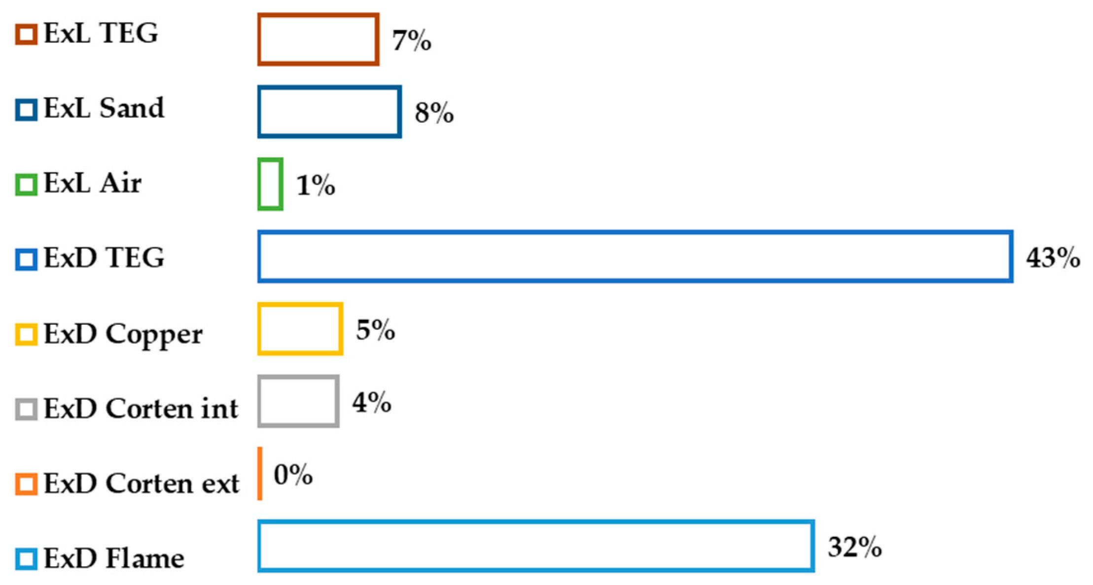
3.1. Exergy Destruction and Losses of Design Configuration

The exergy performance of the analyzed wood fireplace is of 36.2% for a heat input of 26.7 kWt. The highest exergy loss is the one connected to the flue gas stream, which lowers the temperature from the flame to the ambient, as displayed in Equation (4).
ExL fg = Q fg · ( 1 θ fg ) = Q fg · T amb T fg
where T fg is calculated as the logarithmic mean temperature difference between the flame temperature and the ambient temperature.
Indeed, the flue gas exergy loss is the only real one from the system, as the exergy destructions and losses through the walls contribute to heating the housing, which is the real scope of the wood fireplace. However, in this study, the considered products of the system are the flue gases exergy output (which is directly connected to heating the housing) and the power produced by the TE modules, as displayed in Equation (5), while the fuel exergy is considered as the heat input times the Carnot coefficient of the flame, as displayed in Equation (6).
Ex p = Q fg · θ fg +   W   ˙ TOT ,   TE
Ex f = Q in · θ 0
where θ 0 is calculated as 1 T amb T 0 and T0 is the flame temperature.
Therefore, the total exergy input (Exf) is 19.6 kWt, while the exergy loss of the flue gases is 6.4 kWt, which corresponds to 51.2% of the total exergy destruction and losses of the system. The other main contributor to the losses of the system is the glass window, with a value of 1.53 kWt, which corresponds to 12% of the total exergy destruction and losses of the system.
Figure 4 displays the exergy destruction and losses of the walls of the wood fireplace, adimensionalized with respect to the exergy input. Walls 1 and 3 have the same configuration, as they have the same numbers of TE modules (2); on the other hand, wall 2 has 3 TE modules; therefore, the heat flux is more concentrated on this wall. The walls that comprise TE modules are the ones that contribute more to the exergy destructions and losses. This is due to the higher flux that is channeled through these walls compared to the bottom and top surfaces. Furthermore, the share of the exergy destruction is higher with respect to the exergy loss, because of the high number of thermal resistances.
Figure 5 and Figure 6 display the detailed share of the exergy destruction and losses on walls 1 and 3 and on wall 2. Particularly, it can be noted from a comparison of the figures, that the number of cells slightly influence the exergy destruction and losses share, impacting only marginally on exergy destruction rate of the flame and of the Corten.
Corten has been divided into external and internal. With external, it is referred to the one in contact with the still air, while the internal it is the one in contact with the copper. The thickness of the Corten is slightly different for the external and internal configuration (0.037 and 0.033 [m], respectively).
The highest exergy destruction is located in the TE modules, due to the very low conversion efficiency of the modules (electric efficiency is only 3.8%). The second highest contribution is given by the exergy destruction from the flame to the wall; the other contributions are far lower, implying a correct design of the thermal resistances system.

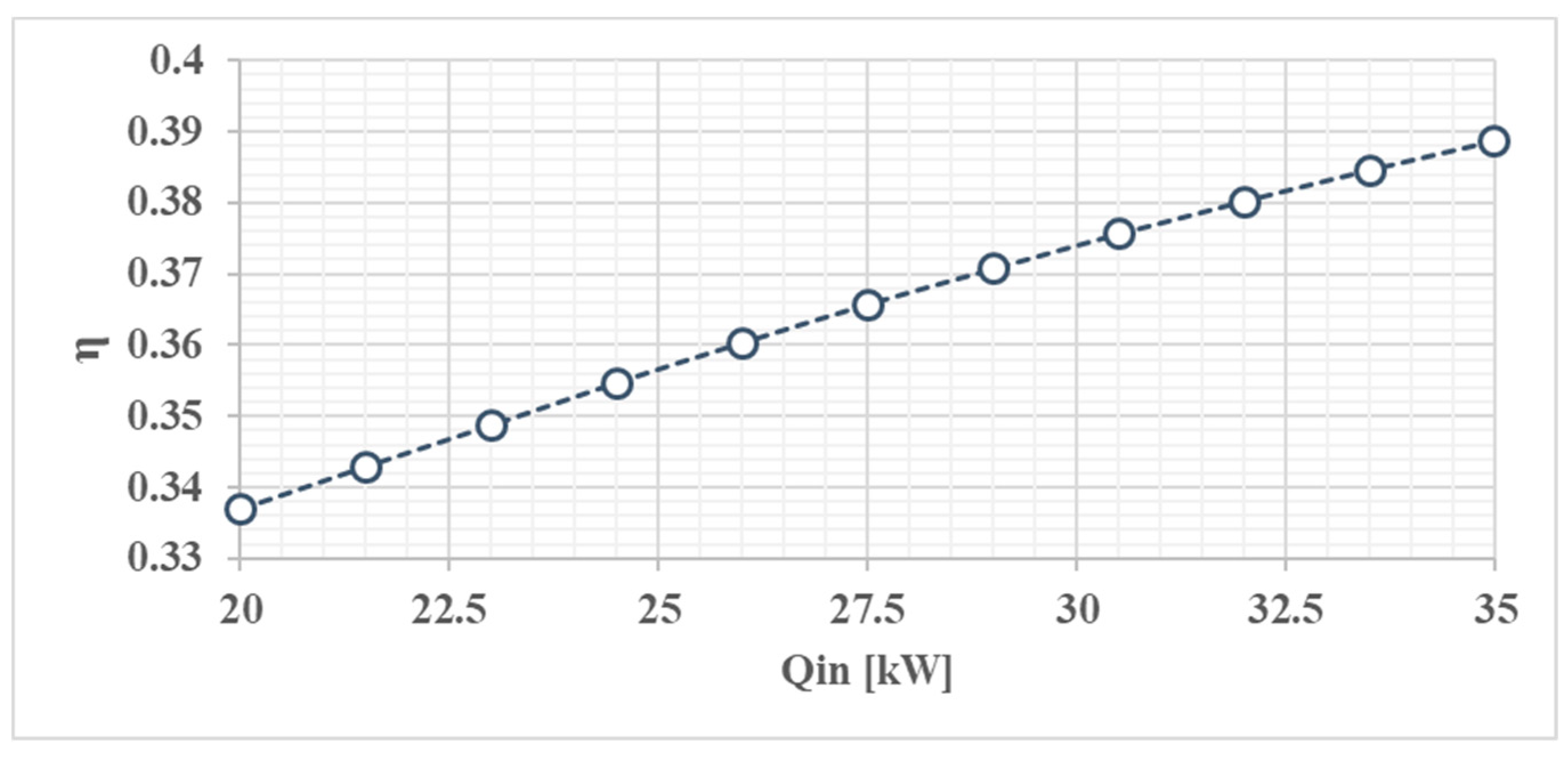
3.2. Sensitivity Analysis of the Main Parameters Affecting the Exergy Efficiency

After the exergy performance of the design case study was assessed, a sensitivity analysis of the main parameters affecting the efficiency of the system has been carried out.
Figure 7 displays the variation of exergy efficiency as a function of the heat input. Particularly, the exergy efficiency increases due to the higher flue gases exergy output, which increases linearly with the heat input.
Figure 8, on the other hand, shows the variation of exergy efficiency as a function of the height of the wood fireplace. This dimensional parameter is the only one affecting the exergy efficiency of the system, as the other length and width of the combustion chamber do not influence the performance of the combustion chamber. The increase in height of the wood fireplace allows to increase the area of the walls, and therefore, more TE modules could be placed; however, this implies that a higher heat flux is located to the walls. As a consequence of the increased heat exchange, the temperature of the flame is colder, decreasing therefore the exergy content of the flue gases. Therefore, the height of the fireplace allows to increase the numbers of modules, but on the other hand, it decreases the temperature of the flame and therefore the exergy efficiency of the system.
Table 2 displays the exergy efficiency as a function of the total number of TE modules. As can be noted from the table, the total number of modules slightly affects the efficiency of the system, as the power output of the cells provides only 2% of the total exergy output of the system.

4. Discussion and Conclusions

An exergy analysis highlighting the inefficiency sources of an innovative design of a thermo-electric wood fireplace has been carried out. Several components were considered in the analysis, which included in the system boundaries all the elements, from the flame to the ambient. An original thermal resistance configuration was also assessed, considering a heat flux concentrator which is able to enhance the performance of the TE modules.
The exergy efficiency of the design case study was found to be of 36.2%, with a high contribution of the exergy values of the flue gases. The main sources of inefficiencies were the exergy loss of the flue gases, the exergy destruction and loss of the glass window, and the radiative destruction component from the flame to each wall. The TE modules also generated considerable exergy destructions and loss. A possible solution to this issue could be utilizing more efficient modules (even if the conversion efficiency range of such modules can be only slightly higher), or to utilize the wasted heat from the TE with a water heat exchanger for the production of sanitary water. In this way, the exergy efficiency of the system would definitely be higher.
After the exergy performance evaluation of the case study, a sensitivity analysis on the main parameters affecting the second law efficiency of the system was carried out. Particularly, it was found that the exegetic efficiency rises with the increase of heat input, as it allows a rise in the exergy content of the flue gases. Conversely, by increasing the height of the fireplace, a reduction of exergy efficiency is produced. This is due to the higher area of the walls, which get a higher heat flux from the flame, which however lower its temperature. A colder flame implies a lower exergy content of the flue gases, reducing thus the exergy efficiency of the system.
Finally, the total number of modules slightly influences the exergy efficiency of the system, as the share of the produced electric power on the total exergy output is only 2%.

Author Contributions

Conceptualization, G.M. and L.T.; methodology, G.M. and L.T.; software, G.M. and L.T.; validation, G.M. and L.T.; formal analysis, G.M. and L.T.; investigation, G.M. and L.T.; resources, G.M.; data curation, G.M. and L.T.; writing—original draft preparation, L.T.; writing—review and editing, G.M. and L.T.; visualization, G.M. and L.T.; supervision, G.M.; project administration, G.M.; funding acquisition, G.M. All authors have read and agreed to the published version of the manuscript.

Conflicts of Interest

The authors declare no conflict of interest.

Nomenclature

ASurface, m2
HFCHeat flux concentrator
TEGThermo electric generators
ExExergy, kW
ExDExergy destruction, kW
ExLExergy loss, kW
hHeat transfer coefficient, W/(m2 K)
HHeight of fireplace, m
LpmLiters per minute
PBPPayback period
QHeat, kW
m ˙ Mass flow rate, kg/s
T Temperature, K
RConduction resistance
Greek symbols
αAbsorption coefficient
εEmissivity
ηExergy Efficiency
σStefan–Boltzmann constant
Subscripts and superscripts
AmbAmbient
CondConduction
ConvConvection
ExtExternal
fFuel
fgFlue gases
InInlet
IntInternal
IrrRadiation
OutOutlet
pProduct
rRelative
0…6 Reference sections of fireplace

Appendix A. Model of Combustion Chamber

Mullikin’s approach was utilized for the radiation modeling from the flame to the walls and the glass window.
The overall heat radiated from the flame (0) to the walls is the following:
Q i r r = 1 6 Q i r r ,     0 ,   i   i = 1 6  
The heat entering the system is determined by the wood consumption rate of the fireplace is the following:
Q i n = m ˙ w ( H i + α c p ; a T a )    
The sensible heat flow exiting the combustion chamber (modelled as a 0-D black box) with the hot combustion gases is given by
Q u = m ˙ w ( 1 + α   ) c p ; g T g
The combustion chamber balance can be written as
Q i n Q i r r Q u = 0  
The flame is conceptually replaced by a cylindrical radiating body (0) (Df = 0.1 m) with emissivity εf = 0.85 (corresponding to a typical wood fire). Each radiation heat rate is evaluated separately, considering both radiation from flame to the walls, and radiation among walls at different temperatures considering the geometrical view factors.
Q i r r ,     i , j   = σ S i   V F j , i ( ε i T i 4 ε i T j 4 )   i ,   j = 1 6
Q i r r ,     0   = j = 1 6 Q i r r , 0 , j           j = 1 6  

Appendix B. Heat Transfer to Thermo-Electric Modules

The radiation model allows to calculate the (equivalent average) temperature of each wall, and consequently the heat rate radiated from the flame to the wall. the glass window is treated as a thin isothermal layer, with heat flux conditions set by the external radiation and natural convection (hot vertical plate) heat losses:
Q i r r ,     0 , 6   = Q g w ,   a   = σ S g w   ( T g w 4 T j 4 ) 1 + ( 1 ε g w ) ε g w + h V P   S g w   ( T g w T a )  
TE modules can be installed on walls 1, 2 and 3, and the heat rate balance can be set in the following terms:
Q i r r ,     0 , 1 + Q i r r ,     0 , 2 + Q i r r ,     0 , 3 = ( n 1 + n 2 + n 3 )   Q i n , T E
On the whole, the TE heat transfer balance is described by the following equations, considering a heat flux concentrator:
Q i n , T E = ( T H T C H ) R o v  
R o v = R c i + R C u + R c
Each TE module provides a power according to the thermoelectric characteristic of the module:
P = 0.0005 ·   ( T T E , H   T T E , C ) · 2 = 20   W  

References

  1. Lund, H.; Ostergaard, P.A.; Connolly, P.; Van Mathiesen, B. Smart Energy and Smart Energy Systems. Energy 2017, 137, 556–565. [Google Scholar] [CrossRef]
  2. Ackermann, T.; Andersson, G.; Soder, L. Distributed generation: A definition. Electric Power Syst. Res. 2001, 57, 195–204. [Google Scholar] [CrossRef]
  3. He, W.; Zhang, G.; Zhang, X.; Ji, J.; Li, G.; Zhao, X. Recent development and application of thermoelectric generator and cooler. Appl. Energy 2015, 143, 1–25. [Google Scholar] [CrossRef]
  4. Champier, D.; Bedecarrats, J.P.; Rivaletto, M.; Strub, F. Thermoelectric power generation from biomass cook stoves. Energy 2010, 35, 935–942. [Google Scholar] [CrossRef]
  5. Champier, D.; Bedecarrats, J.P.; Kousksou, T.; Rivaletto, M.; Strub, F.; Pignolet, F. Study of a TE (thermoelectric) generator incorporated in a multifunction wood stove. Energy 2011, 36, 1518–1526. [Google Scholar] [CrossRef]
  6. Zheng, X.F.; Yan, Y.Y.; Simpson, K. Potential candidate for the sustainable and reliable domestic energy generation—Thermoelectric cogeneration system. Appl. Thermal Eng. 2013, 53, 305–311. [Google Scholar] [CrossRef]
  7. Nuwayhid, R.Y.; Rowe, D.M.; Min, G. Low cost stove-top thermoelectric generator for regions with unreliable electricity supply. Renew. Energy 2003, 28, 205–222. [Google Scholar] [CrossRef]
  8. Nuwayhid, R.Y.; Shihadeh, A.; Ghaddar, N. Development and testing of a domestic woodstove thermoelectric generator with natural convection cooling. Energy Convers. Manag. 2005, 46, 1631–1643. [Google Scholar] [CrossRef]
  9. Lertsatitthanakorn, C. Electrical performance analysis and economic evaluation of combined biomass cook stove thermoelectric (BITE) generator. Bioresource Technol. 2007, 98, 1670–1674. [Google Scholar] [CrossRef] [PubMed]
  10. Ding, L.C.; Meyerheinrich, N.; Tan, L.; Rahaoui, K.; Jain, R.; Akbarzadeh, A. Thermoelectric power generation from waste heat of natural gas water heater. Energy Procedia 2017, 110, 32–37. [Google Scholar] [CrossRef]
  11. Sornek, K.; Filipowicz, M.; Rzepka, K. The development of a thermoelectric power generator dedicated to stove-fireplaces with heat accumulation systems. Energy Convers. Manag. 2016, 125, 185–193. [Google Scholar] [CrossRef]
  12. Sornek, K.; Filipowicz, M.; Zoladek, M.; Kot, R.; Mikrut, M. Comparative analysis of selected thermoelectric generators operating with wood-fired stove. Energy 2019, 166, 1303–1313. [Google Scholar] [CrossRef]
  13. Baldini, A.; Cerofolini, L.; Fiaschi, D.; Manfrida, G.; Talluri, L. Thermodynamic assessment on the integration of thermo-electric modules in a wood fireplace. Civ. Environ. Eng. Rep. 2019, 29, 218–235. [Google Scholar] [CrossRef]
  14. Szargut, J.; Morris, D.R.; Steward, F.R. Exergy Analysis of Thermal, Chemical, and Metallurgical Processes; Hemisphere Publishing Corporation: Washington, DC, USA, 1988. [Google Scholar]
  15. Kotas, T.J. The Exergy Method of Thermal Plant Analysis; Butterworths: London, UK, 1985. [Google Scholar]
  16. Bejan, A.; Tsatsaronis, G.; Moran, M. Thermal Design and Optimization; John Wiley & Sons, Inc.: New York, NY, USA, 1996. [Google Scholar]
Figure 1. Schematic of heat flux concentrator box.
Proceedings 58 00010 g001
Figure 2. Schematic (a) of household fireplace with integrated hot water storage and (b) schematic of combustion chamber with heat flux concentrators.
Proceedings 58 00010 g002
Figure 3. Equivalent thermal resistance network for the thermo-electric wood fireplace.
Proceedings 58 00010 g003
Figure 4. Relative exergy destruction and losses of the walls within the combustion chamber.
Proceedings 58 00010 g004
Figure 5. Detailed share of exergy destruction and loss of walls 1 and 3.
Proceedings 58 00010 g005
Figure 6. Detailed share of exergy destruction and loss of wall 2.
Proceedings 58 00010 g006
Figure 7. Exergy efficiency of the wood fireplace as function of heat input.
Proceedings 58 00010 g007
Figure 8. Exergy efficiency of the wood fireplace as function of combustion chamber height.
Proceedings 58 00010 g008
Table 1. Wood fireplace dimensions.
Dimensions[m]
Overall Width1
Overall Depth0.7
Overall Height1.6
Combustion Chamber Width0.78
Combustion Chamber Depth0.5
Combustion Chamber Height0.43
Table 2. Exergy efficiency of the wood fireplace as function of total number of TE modules.
# of TE modulesη [%]
636.03
735.97
835.96
Publisher’s Note: MDPI stays neutral with regard to jurisdictional claims in published maps and institutional affiliations.

