Article

Real-Time Monitoring of Parameters and Diagnostics of the Technical Condition of Small Unmanned Aerial Vehicle’s (UAV) Units Based on Deep BiGRU-CNN Models

Department of Automation of Technological Processes, Ufa State Aviation Technical University, 450077 Ufa, Russia
*
Author to whom correspondence should be addressed.
Drones 2022, 6(11), 368; https://doi.org/10.3390/drones6110368
Submission received: 30 October 2022 / Accepted: 16 November 2022 / Published: 21 November 2022
(This article belongs to the Special Issue Advances in Deep Learning for Drones and Its Applications)

Abstract

:
The paper describes an original technique for the real-time monitoring of parameters and technical diagnostics of small unmanned aerial vehicle (UAV) units using neural network models with the proposed CompactNeuroUAV architecture. As input data, the operation parameter values for a certain period preceding the current and actual control actions on the UAV actuators are used. A reference parameter set model is trained based on historical data. CompactNeuroUAV is a combined neural network consisting of convolutional layers to compact data and recurrent layers with gated recurrent units to encode the time dependence of parameters. Processing provides the expected parameter value and estimates the deviation of the actual value of the parameter or a set of parameters from the reference model. Faults that have led to the deviation threshold crossing are then classified. A smart classifier is used here to detect the failed UAV unit and the fault or pre-failure condition cause and type. The paper also provides the results of experimental validation of the proposed approach to diagnosing faults and pre-failure conditions of fixed-wing type UAVs for the ALFA dataset. Models have been built to detect conditions such as engine thrust loss, full left or right rudder fault, elevator fault in a horizontal position, loss of control over left, right, or both ailerons in a horizontal position, loss of control over the rudder and ailerons stuck in a horizontal position. The results of estimating the developed model accuracy on a test dataset are also provided.

1. Introduction

The paper proposes an original technique for the control systems of small unmanned aerial vehicles to monitor parameters and diagnose the technical condition of their units. This technique can be used as part of both real-time control systems directly on board a small unmanned aerial vehicle (UAV) and remote ones generating a control action via telemetry channels.
A technique for the technical monitoring and diagnosis of UAV’s onboard systems with decision-making support and a set of on-flight state checking equipment with a smart decision-making support system that allows to implement it are currently known [1]. This technique involves classifying the values of critical monitoring parameters characterizing the UAV onboard the system’s critical components according to any feature. Thereat, qualitative estimates are assigned to each parameter to identify pre-failure conditions of the UAV’s onboard system (OBS) and perform proactive diagnostics. Optimal diagnostic sequences are also formed as ranked lists of three-level precedents. The technique uses a knowledge base engine, a precedent library, and a Bayesian belief network for troubleshooting; however, it supposes checking the UAV tool kit-telemetry system while generating recommendations for the decision maker. Herewith, this technique does not allow using the diagnostic results by the UAV’s onboard control system to generate control actions.
Other known techniques for troubleshooting UAVs, in particular, smart aircraft troubleshooting and maintenance systems described, respectively, in [2,3], have a similar disadvantage—providing possible aircraft fault diagnoses without the possibility of autonomously using the diagnostic result on board the UAV. Note that fairly many studies are currently underway on the application of machine learning technologies using compact neural processing units (NPUs) on board small UAVs to solve image recognition and object identification problems [4,5,6,7,8,9], as part of control systems to implement sliding mode control in the fixed-wing type UAV flights [10], compensate Gated Recurrent Unit (GRU) network-based navigation system errors [11], land on a moving target [12], plan UAV formation flights [13], etc.
Many studies are devoted to diagnosing fixed-wing type UAV sensors and actuators, e.g., in Ref. [14], to estimate the fixed-wing type UAV’s inertial measurement unit condition, a nonlinear proportional integral unknown input observer-based system is implemented, and in Ref. [15], a wavelet transform-based approach is proposed. In Ref. [16], an RBF (radial basis function) neural network-based smart system is implemented to detect faults of the UAV’s gyroscope and accelerometer sensors. Paper [17] describes a technique for diagnosing a small UAV’s angular velocity sensor based on the support vector machine combined with the principal component analysis to detect faults.
Some studies are devoted to monitoring the UAV’s rotor condition: in Ref. [18], a duplicating simulation-based decentralized system is implemented for a group of UAVs; in Ref. [19], a linear parameter varying proportional integral unknown input observer-based monitoring system is used.
A Bayesian classifier-based UAV aileron condition monitoring using the emergency landing system is described in Ref. [20].
In Ref. [21], a fault-tolerant UAV control system is implemented to maintain the planned trajectory based on the random forest technique.
The drawback of most studies devoted to the monitoring of the UAV unit conditions is diagnosing the UAV condition at a specific time instant without considering the factor of the cumulative fault effect, such as a delay in the reaction time of actuators or changes in parameters in the early stages of a malfunction, or a change in the smoothness of the reaction to a jump.
Currently, there are concepts of fault-tolerant control over not only a single UAV but also a UAV formation, e.g., Ref. [22] describes the concept of a fault-tolerant formation for the case of loss of any UAV in it. When any UAV is lost, the objective function is corrected, which allows for maintaining the entire group’s performance. The assumption of a working diagnostic module capable that can timely detect faults is among the significant drawbacks of this concept. Herewith, it also has problems associated with the possible collision with other UAVs in the group and cascade destruction of the formation when any UAV is lost for the group of UAVs located at different heights or close to each other. Such a problem is solved by implementing a predictive diagnostic module. Thus, developing a diagnostic module is required, which will timely predict the UAV fault to further adaptively reconfigure the entire group. A decentralized formation adaptive reconfiguration technique capable of successfully using the diagnostic module concept described therein is given in Ref. [23]. To implement such diagnostic models and estimate their diagnostic ability, an experimental dataset is required that contains data on the UAV performance in both normal flight mode and the fault tolerant-mode.
Thus, the novelty of the diagnostic and monitoring technique herein is implementing a neural network model of original architecture to monitor the UAV parameters and determine the probability of faults and pre-failure conditions, consisting of convolutional layers to create a compact aggregated representation of parameters and bidirectional GRU layers to consider the cumulative fault effect and the actuator response inertia.

2. Description of the Proposed Diagnostic and Monitoring Technique

The objective of the invention proposed herein is to expand the opportunities for monitoring technical condition parameters of small UAV units and diagnosing them during operation.
The technical result comprises identifying deviations of the small UAV system parameters from the expected values, the failed system, the fault cause and type, and the pre-failure conditions.
The technique proposed herein involves the following: the reference model of the original CompactNeuroUAV neural network architecture generates the expected parameter value based on the operation parameter values for a certain period preceding the current and actual commands to the UAV actuators and defines the deviation of the actual value of individual parameters or their combination from the reference model. Faults that have led to the deviation threshold crossing are then classified. A smart classifier is here used to identify the failed system and the fault cause and type. The relationship of parameters in the CompactNeuroUAV neural network architecture is based on a combined neural network consisting of convolutional layers (CNN, Convolutional Neural Network) [24,25,26] to compact data and bidirectional recurrent layers with controlled units (GRU, Gate Recurrent Unit) [26,27,28] to encode the time dependence of the parameters.
Figure 1 provides the graphical diagram of a single GRU unit within the proposed architecture, processing the parameter vector values according to the system of equations:
z t = σ g ( W z x t + U z h t 1 + b z ) r t = σ g ( W r x t + U r h t 1 + b r ) h t = z t h t 1 + ( 1 z t ) σ h ( W h x t + U h ( r t h t 1 ) + b h )
Here, x t is an input vector, h t is an output vector, z t is an update gate vector, r t is a reset gate vector, W, U, and b are parametric matrices and a vector.
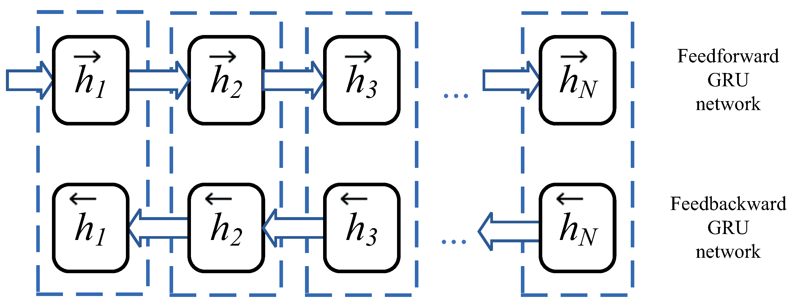
Figure 2 shows a bidirectional network consisting of GRUs designed to encode a vector of values obtained at discrete time instants.
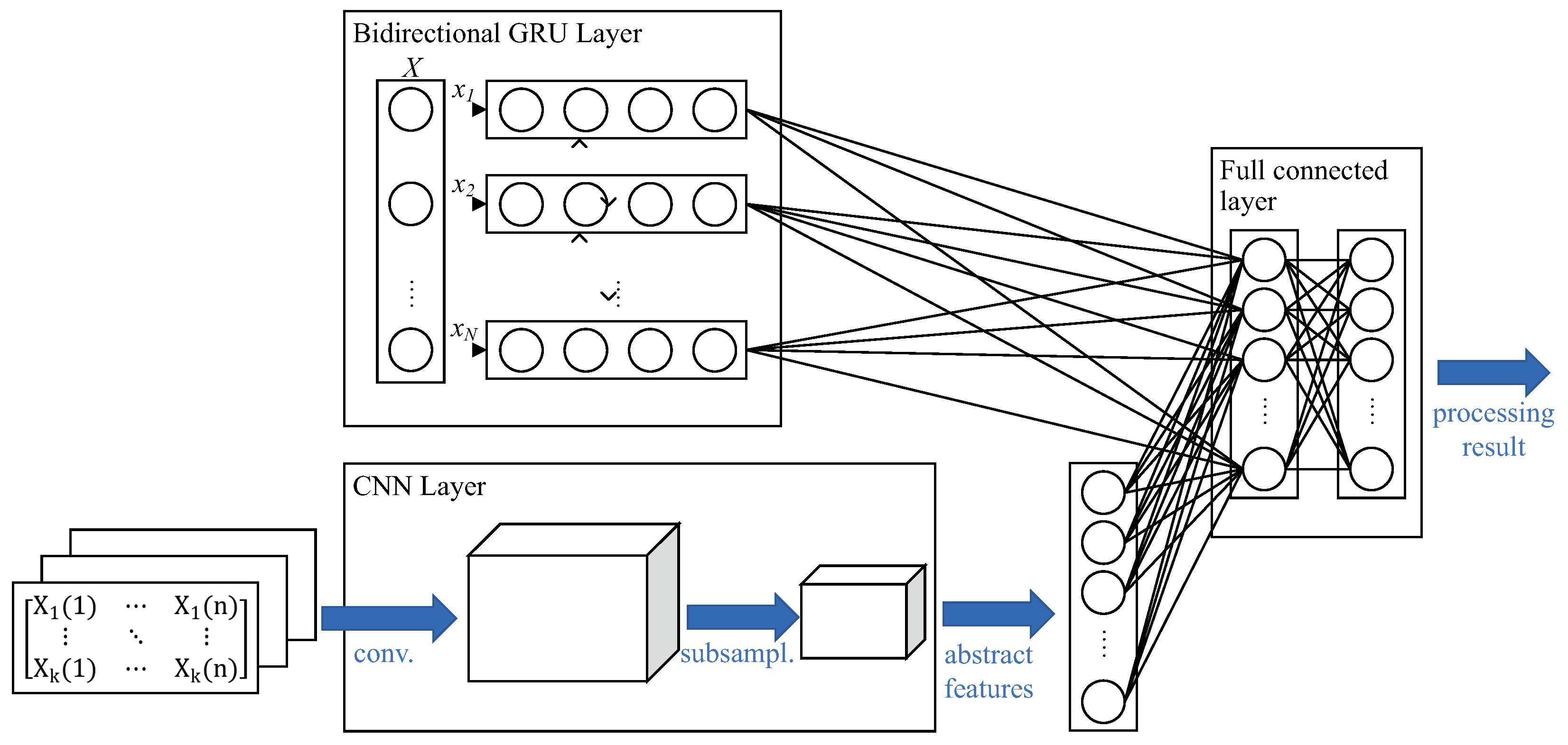
Processing UAV parameter inputs by CNN allows for forming a generalized abstract feature for several parameters. Sets of bidimensional time matrices form three-dimensional matrix units, and then, convolution is applied to them. The convolution result is a highly abstract feature, and after the convolution, its results are processed by a separate layer with subsampling. Figure 3 shows a diagram of a CNN for data processing.
Figure 4 shows the general diagram of the proposed CompactNeuroUAV architecture.
The diagnostic model is built by processing a previously collected database containing parameters recorded by the onboard control system and faults that have occurred during UAV flights. The parameter relationship reference model is built by the maximum sampling frequency of the recorded parameters with the normalization of values within the range [0, 1] and further defining the missing time series values by linear interpolation. The parameter relationship reference model is then fixed by training neural networks using the obtained dataset. To optimize the number of computational operations required to detect deviations in parameters and identify pre-failure conditions, subsampling of the recorded CNN data is used.
To fix the time dependence of parameter values and estimate the cumulative fault nature, the GRU layer is used with the number of units defined in the course of training the reference model by the number of discrete values in the time interval. Thereat, the time range’s lower interval is limited by the value corresponding to the minimum sampling frequency of the UAV parameters chosen to build the model.
The reference model output values are:
  • Estimated deviation of the expected single parameter value, specifying the deviation magnitude calculated by reducing the normalized parameter value to its measurement range;
  • Estimated deviation of the set of parameters, specifying the deviation as a percentage of the normalized value of the expected set of parameters;
  • The fault classifier output value, which is one of the possible types, specifying the estimated probability of this fault class.
Thus, the proposed technique for the real-time monitoring of parameters and diagnostics of the technical condition of the unmanned aerial vehicle units is implemented as a sequence of the following operations:
  • Preparing the training data—the use of archived data on the UAV unit parameters and faults during flights with normalization and reduction to the maximum processing frequency.
  • Training the neural network with the proposed CompactNeuroUAV architecture with the generation of the required target value:
    • Estimating the individual parameter deviation from the expected value (Algorithm 1 with S e n s o r C o u n t = 1 );
    • Estimating the deviation of the set of parameters (Algorithm 1 with S e n s o r C o u n t > 1 );
    • Estimating the availability and probability of a fault or pre-failure condition (Algorithm 2).
  • Validating the developed models.
  • Integrating the developed models into the UAV control system.
Algorithm 1 Algorithm for estimating the deviation of any UAV parameter or a set of parameters from the expected reference as a neural network model with the CompactNeuroUAV Architecture
  • Require: N 1
  • Require: S e n s o r C o u n t 1
  •   fori = 1 to N do        ▹ For each deviation estimation model
  •       P[i] ← GetRealtimeSensorValues(SensorCount, i)
  •       Pnorm[i] ← Normalization(P[i])
  •       e ← EstimateDeviationCompactNeuroUAV[i](Pnorm[i])
  •       if  N > M a x D e v i a t i o n [ i ]  then
  •            A l a r m t r u e
  •       else
  •            A l a r m f a l s e
  •       end if
  •       WriteToLog(e, Pnormi)
  •   end for
The developed models are integrated into the UAV control loop as follows:
  • At each t i time instant, a set of input values of normalized parameter-time matrices is generated, where the timestamp is within the range t i N , …, t i 1 ;
  • This set of normalized parameters is processed by the CompactNeuroUAV neural network; as a result, for each time instant, an actual compact aggregate representation of the parameter sets is generated in real-time;
  • Deviations of the compact aggregated representation from the expected reference are estimated; the used model is marked as EstimateDeviationCompactNeuroUAV[i] in Algorithm 1;
  • In the presence of a pre-trained classifier, a compact aggregated representation is used to estimate the presence of a certain-class fault or a pre-failure condition as ClassifierCompactNeuroUAV[i] in Algorithm 2.
Algorithm 2 Algorithm for identifying the UAV faults or pre-failure conditions based on neural network models with the CompactNeuroUAV architecture
  • Require: N 1
  • Require: S e n s o r C o u n t 1
  •   for i = 1 to N do        ▹ For each deviation estimation model
  •       P[i] ← GetRealtimeSensorValues(SensorCount, i)
  •       for j = 1 to M do                ▹ For each sensor
  •           if  P [ i ] [ j ] > M a x S e n s o r V a l u e [ i ] or P [ i ] [ j ] < M i n S e n s o r V a l u e [ i ]  then
  •              return Identifying fault
  •           end if
  •       end for
  •       Pnorm[i] ← Normalization(P[i])
  •       classes ← ClassifierCompactNeuroUAV[i](Pnormi)
  •       WriteToLog(classes, Pnormi)
  •   end for
The integration of the developed models into the control system of a single UAV makes it possible to implement a program for notifying the operator or for automatic safe landing of the aircraft when pre-fault conditions are detected in real time, as well as a controlled exclusion from the formation of a group flight of the UAV upon detection of pre-failure conditions of the aircraft.
The main disadvantage of integrating such models into the control system is the need for the presence of specialized neural processing units (NPU) on board the UAV for the effective operation of the models. As a result, when designing a UAV, it is necessary to take into account the additional weight and energy costs required for the operation of such neural accelerators (NPUs).

3. An Example of Implementing the Technique for a Fixed-Wing Type UAV

The proposed technique has been estimated on a simulation model using an experimental dataset [29,30] obtained for the Carbon Z T-28 fixed-wing type UAV consisting of the following:
  • Two-meter wingspan;
  • Front engine;
  • Ailerons;
  • Flaperons (flap ailerons);
  • Elevator;
  • Rudder.
To simulate faults in various UAV units, a modified control system was used to collect experimental flight data, which allows for the implementation of the following types of faults for an aircraft flying in autopilot mode:
i
Complete engine fault (shutdown);
ii
Elevator fault in a horizontal position;
iii
Rudder fault in the full right, full left, or middle position;
iv
Fault of the ailerons with the simulation of right, left, or both ailerons stuck in a horizontal position.
The ALFA dataset, which was used as part of the research work, presents flight data lasting from 26 to 233.4 s. To simulate errors, the authors of this dataset introduced an additional UAV control system in such a way that, at the command of the operator, the engine was turned off or the passage of the control command to the actuators was disabled.
Experimental flight dataset files are tagged to contain only autopilot flight data and include valid fault data only if any simulated fault actually occurs. Each file contains data on flights with one fault only. The UAV position GPS data, actual and target roll, pitch, speed, and yaw values measured by sensors and set by autopilot, the local unit conditions, and the overall UAV state estimate are used as the parameters monitored to estimate the technical UAV unit conditions.
Table 1 provides a general summary list of the simulated types of faults and the UAV flight duration before the fault and after its simulation.
To implement the proposed technique for the real-time monitoring of parameters and diagnostics of technical conditions of the unmanned aerial vehicle units, the following sequence of actions was performed:
i
Labeling the experimental time series data:
(a)
Experimental flight data are divided into time intervals of 1 second; for signals with a sampling frequency less than the maximum 25 Hz, the dataset is completed by linear interpolation;
(b)
A label characterizing the presence of a fault is assigned to each interval from paragraph 1.a: flight without a fault, flight with a fault, transition interval for the fault manifestation. Transition intervals are chosen with the fault simulation start moments falling on different interval regions;
(c)
The resulting set of intervals is split into training (40%), cross-validation (10%), and test (50%) sets, considering the interval type (Table 1) and fault label (paragraph 1.b).
ii
The time series obtained at stage 1 is normalized by the measured parameter range for the UAV position GPS data and the actual and target roll, pitch, speed, and yaw values measured by the sensors and set by the autopilot.
iii
Deep neural network models with the proposed CompactNeuroUAV architecture are trained using training and cross-validation sets:
(a)
To estimate the deviation of a single pitch, roll, or yaw parameter from the expected reference considering the actuator response inertia;
(b)
To estimate the deviation of the set of roll, pitch, speed, and yaw parameters from the expected reference;
(c)
Classifier model to estimate the presence of a fault or pre-failure condition, specifying the estimated probability of this fault class
iv
The trained models are tested on a test set.
For the implementation and testing of the algorithms, the environment was used corresponding to that used in the collection of experimental data for the ALFA dataset [30]: Linux Ubuntu 16.04 (Xenial) and Robot Operating System (ROS) Kinetic Kame and a Nvidia GPU corresponding in performance to the Nvidia Jetson TX2 NPU. The processing of time series of experimental data was carried out in the described environment with the simulation of all types of errors presented in the dataset as a sequence of incoming data with reference to a timestamp
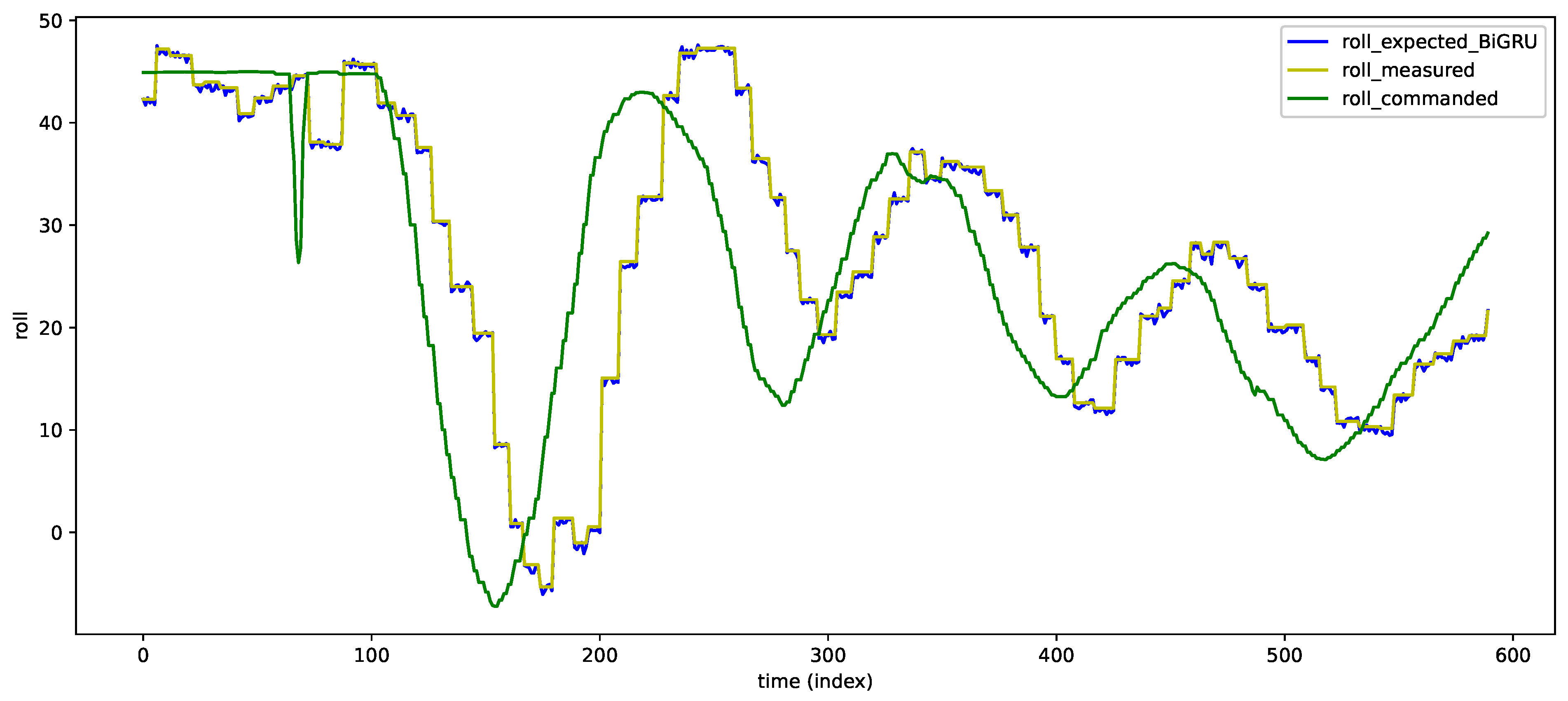
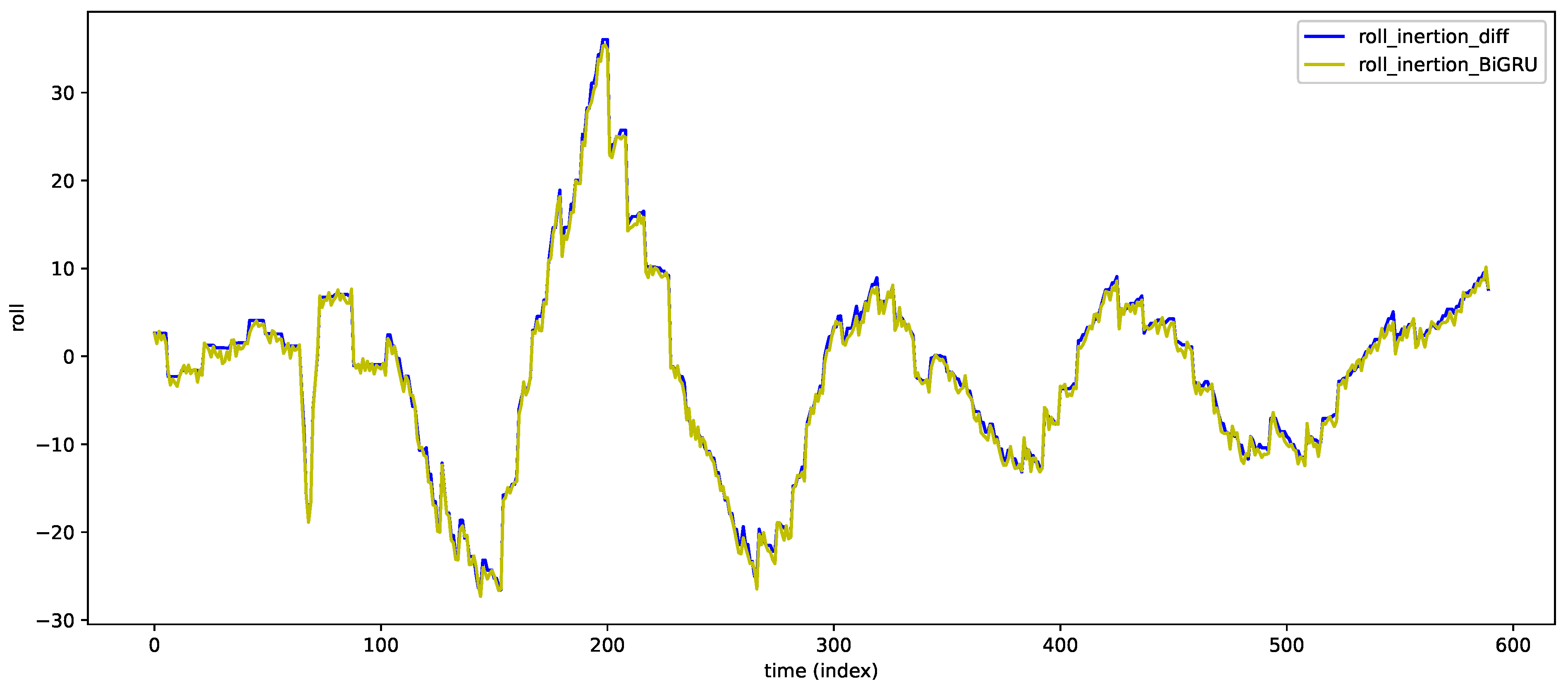
Figure 5, Figure 6, Figure 7, Figure 8, Figure 9 and Figure 10 provide the estimation results for the deviation of an individual pitch, roll, or yaw parameter and the inertia of the monitored parameter generated by the BiGRU layers of the CompactNeuroUAV network for a single flight without fault. As mentioned above, the data of each flight was split into short intervals and used as training, validation, and test sets. Therefore, it is obvious that in the figures, a part of each curve generated by the NN model is the training data re-processing result. However, such an additional validation allows estimating the NN model efficiency over the entire flight range and not only on short data sets.
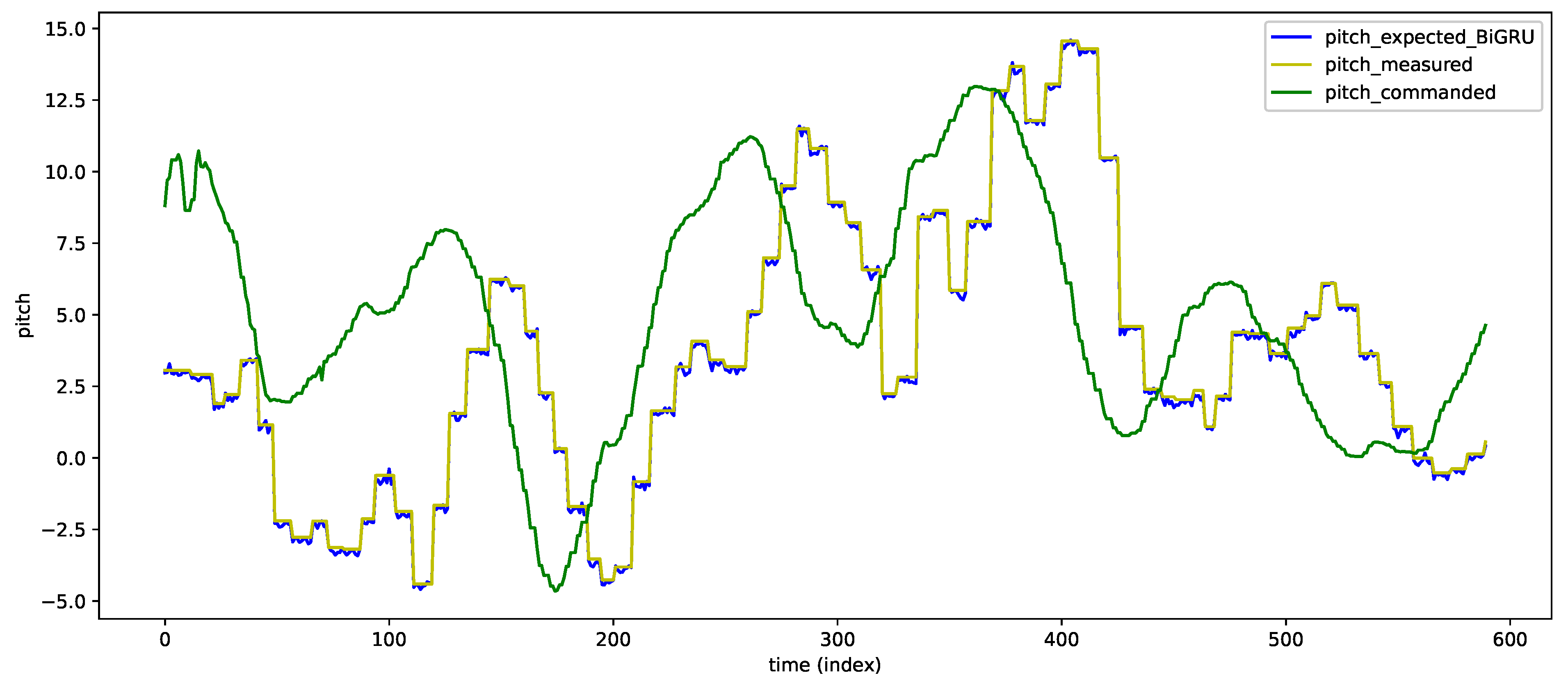
In Figure 5, Figure 7 and Figure 9, the X axis shows discrete time instants, and the Y axis shows the UAV onboard the system’s monitored parameter change command (commanded), the actually measured value (measured), and the NN model-generated expected value (expectedGRU).
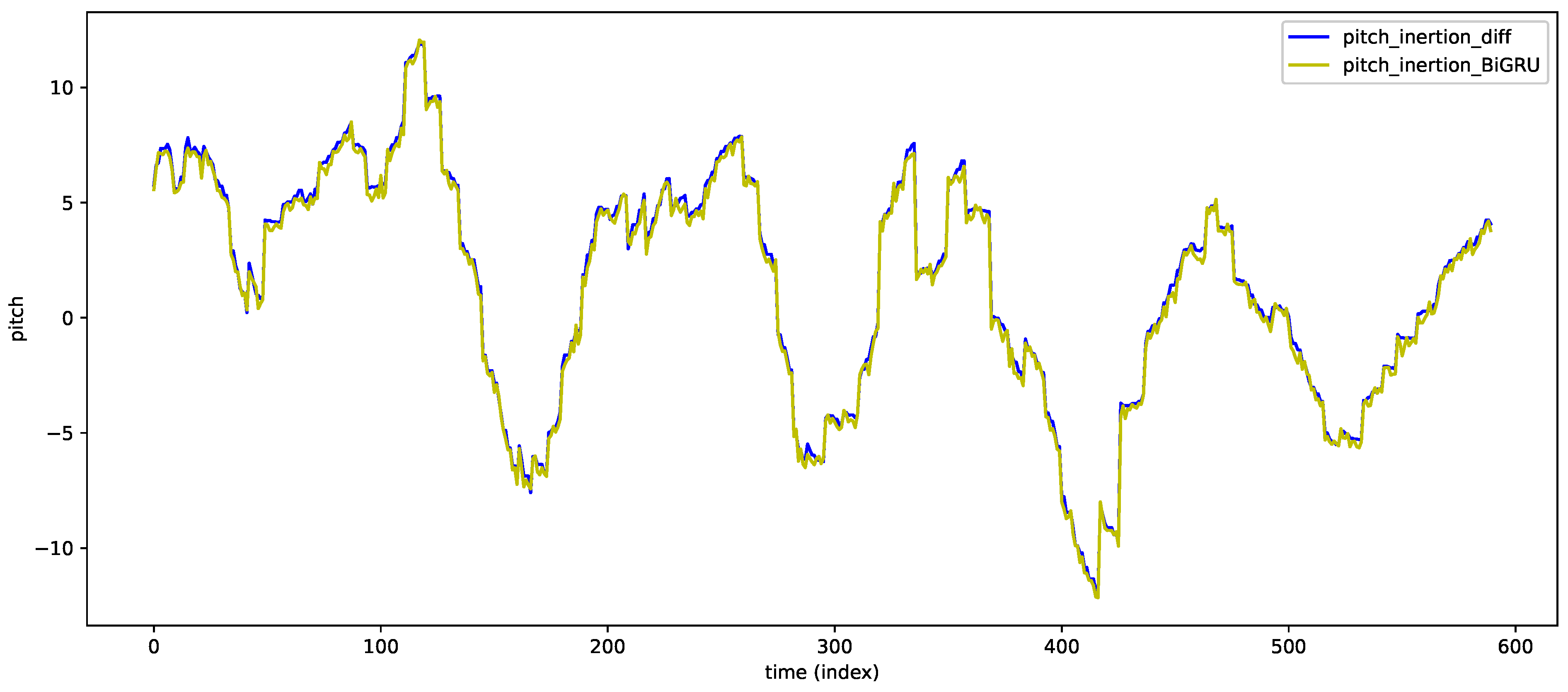
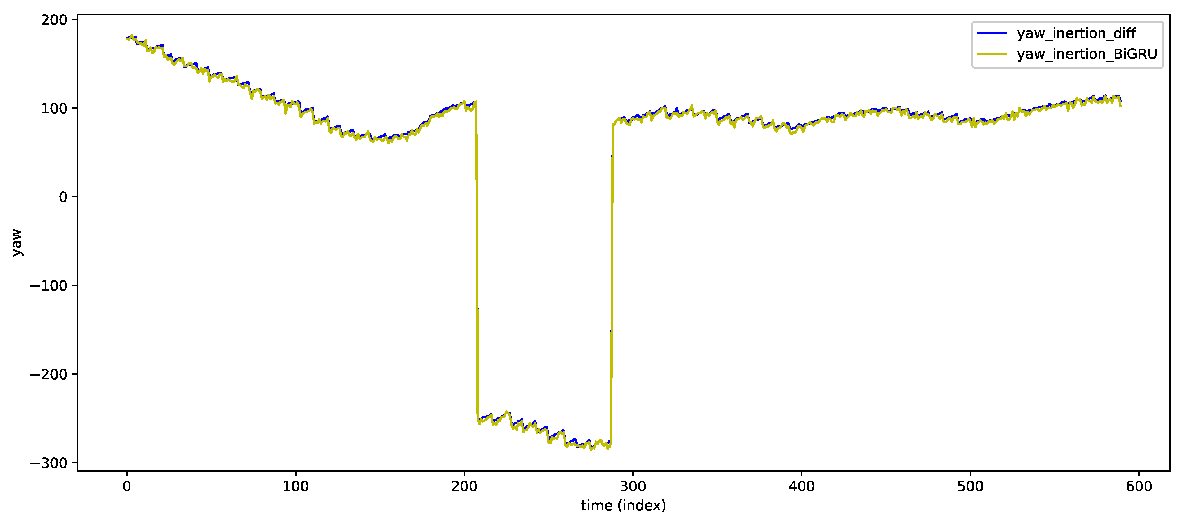
In Figure 6, Figure 8, and Figure 10, the Y axis shows the actual deviation of the monitored parameter and the expected one generated by the CompactNeuroUAV model. The deviation curves allow visually estimating the accuracy of considering the inertia of the UAV unit’s response to the control commands by the NN model. The figures demonstrate that the parameter deviation estimation accuracy is quite high, and the shape of the deviation curve generated by the CompactNeuroUAV model virtually repeats that of the actual value curve.
Thereat, the accuracy of the models for estimating the deviation of the pitch, roll, and yaw values from the reference ones was, respectively, 91, 87.2, and 89.6%.
The accuracy of the model for estimating the deviation of the set of roll, pitch, speed, and yaw parameters from the expected reference was 96%.
Table 2 provides the pre-failure condition identification testing results, specifying the proportion of false positive (FP) and false negative (FN) detections of fault or pre-failure condition of any UAV unit.
The presence of any class of fault or pre-failure condition was estimated by the corresponding CompactNeuroUAV model output with a probability of at least 75%. Validation of the developed models was done in two ways: validation over short time intervals and validation when simulating a full flight—the data of each particular flight was the input information for the models, while the situation of sequential receipts of these data in real time was simulated.
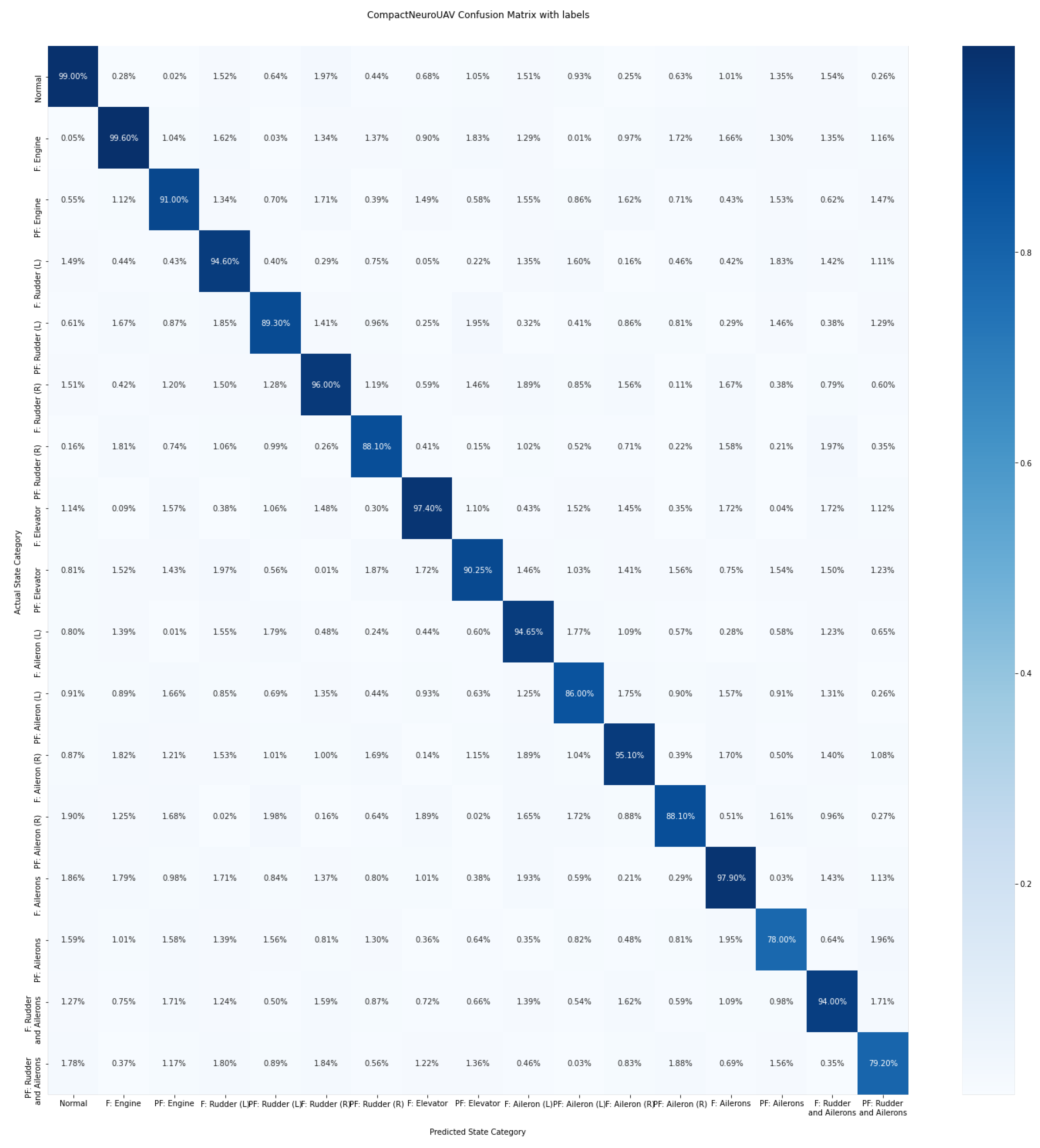
Figure 11 shows the results of testing the trained NN model for detecting faults and pre-failure conditions as a confusion matrix, where F is the fault, PF is the pre-failure condition, (L) is left (aileron or full left rudder position), and (R) is right (aileron or full right rudder position).
As result, the realized common fault or pre-fault state detection CompactNeuroUAV model accuracy is 93.36%, which is 5% better than the original approach, based on using the Recursive Least Squares algorithm in Ref. [30]. Using other types of recurrent neural networks for encoding time series data such as LSTM and BiLSTM was also less effective, as these models showed an accuracy 83% and 91.1% and it took one and a half and two times longer to train the models.

4. Conclusions

This paper provides the results of developing an approach to monitor and diagnose the state of an UAV in real-time. An original NN architecture was developed, which allows monitoring the deviation of parameters from the expected values and detecting faults and pre-failure conditions.
The solution implementation and evaluation results are provided for a small fixed-wing type UAV. The proposed approach can further be used to generate compensating control actions when any parameter significantly deviates directly on board the UAV using compact onboard NPUs. The identified pre-failure conditions can also be used to build control programs for the UAV control system for decision-making, and the individual UAV condition identification results can be used to promptly reconfigure formations during group flights.
The proposed approach offers a complex model for identifying faulty and pre-faulty states of the UAV, and its limitations also expire from here. The implementation of identifying a certain class of faults from the list presented in this work requires the presence of all input data, and the absence of any indications or sensor failure leads to the fact that the proposed models can no longer be used to make decisions about the direct state of the UAV elements.
Another limitation is the need for archival information about the flight parameters preceding the failure states in order to implement such models for a specific type of unmanned aerial vehicle. The adaptation and implementation of diagnostic models for other types of UAVs requires additional research, taking into account the operational information available in UAVs about flight parameters. The aim of the authors was to show an efficient neural network architecture for data processing during the flight based on the division of time data into short intervals to form a diagnosis of the state of the UAV elements. The authors hope that the approach presented in the paper will help other researchers in the tasks of predictive fault detection based on time series data.

Author Contributions

Methodology, data processing, and writing K.M.; writing—review and editing, T.M. and R.M.; project administration, T.M. All authors have read and agreed to the published version of the manuscript.

Funding

The study has been supported by the Ministry of Science and Higher Education of the Russian Federation as part of Agreement No. 075-15-2021-1016.

Data Availability Statement

Not applicable.

Conflicts of Interest

The authors declare no conflict of interest.

Abbreviations

The following abbreviations are used in this manuscript:
UAVUnmanned Aerial Vehicle
GRUGated Recurrent Unit
RBFRadial Basis Function
CNNConvolutional Neural Network
BiGRUBidirectional Gated Recurrent Unit Neural Network
NNNeural Network
FPFalse Positive (classification result)
FNFalse Negative (classification result)
GPSGlobal Positioning System

References

  1. Levin, M.; Smirnov, V.; Ulanov, M.; Davidchuk, A.; Buravlev, D.; Zimin, S. Method for Technical Control and Diagnostics of Onboard Systems of Unmanned Aerial Vehicle with Decision Support and Complex of Control and Checking Equipment with Intelligent Decision Support System for Its Implementation. RU Patent RU 2 557 771 C1, 27 July 2015. [Google Scholar]
  2. Dolzhikov, V.; Ryzhakov, S.; Perfiliev, O. Aircraft Intelligent Troubleshooting System. RU Patent RU 2 680 945 C1, 17 August 2019. [Google Scholar]
  3. Dolzhikov, V.; Ryzhakov, S.; Perfiliev, O. Intelligent Aircraft Maintenance System. RU Patent RU 2 729 110 C1, 4 August 2020. [Google Scholar]
  4. Pandey, A.; Jain, K. An intelligent system for crop identification and classification from UAV images using conjugated dense convolutional neural network. Comput. Electron. Agric. 2022, 192, 106543. [Google Scholar] [CrossRef]
  5. Zhu, J.; Zhong, J.; Ma, T.; Huang, X.; Zhang, W.; Zhou, Y. Pavement distress detection using convolutional neural networks with images captured via UAV. Autom. Constr. 2022, 133, 103991. [Google Scholar] [CrossRef]
  6. Ishengoma, F.S.; Rai, I.A.; Ngoga, S.R. Hybrid convolution neural network model for a quicker detection of infested maize plants with fall armyworms using UAV-based images. Ecol. Inform. 2022, 67, 101502. [Google Scholar] [CrossRef]
  7. Behera, T.K.; Bakshi, S.; Sa, P.K. Vegetation Extraction from UAV-based Aerial Images through Deep Learning. Comput. Electron. Agric. 2022, 198, 107094. [Google Scholar] [CrossRef]
  8. Medaiyese, O.O.; Ezuma, M.; Lauf, A.P.; Guvenc, I. Wavelet transform analytics for RF-based UAV detection and identification system using machine learning. Pervasive Mob. Comput. 2022, 82, 101569. [Google Scholar] [CrossRef]
  9. Wei, L.; Luo, Y.; Xu, L.; Zhang, Q.; Cai, Q.; Shen, M. Deep Convolutional Neural Network for Rice Density Prescription Map at Ripening Stage Using Unmanned Aerial Vehicle-Based Remotely Sensed Images. Remote Sens. 2022, 14, 46. [Google Scholar] [CrossRef]
  10. Wang, X.; Sun, S.; Tao, C.; Xu, B. Neural sliding mode control of low-altitude flying UAV considering wave effect. Comput. Electr. Eng. 2021, 96, 107505. [Google Scholar] [CrossRef]
  11. Zhao, D.; Liu, Y.; Wu, X.; Dong, H.; Wang, C.; Tang, J.; Shen, C.; Liu, J. Attitude-Induced error modeling and compensation with GRU networks for the polarization compass during UAV orientation. Measurement 2022, 190, 110734. [Google Scholar] [CrossRef]
  12. Abo Mosali, N.; Shamsudin, S.S.; Mostafa, S.A.; Alfandi, O.; Omar, R.; Al-Fadhali, N.; Mohammed, M.A.; Malik, R.Q.; Jaber, M.M.; Saif, A. An Adaptive Multi-Level Quantization-Based Reinforcement Learning Model for Enhancing UAV Landing on Moving Targets. Sustainability 2022, 14, 8825. [Google Scholar] [CrossRef]
  13. Puente-Castro, A.; Rivero, D.; Pazos, A.; Fernandez-Blanco, E. Using Reinforcement Learning in the Path Planning of Swarms of UAVs for the Photographic Capture of Terrains. Eng. Proc. 2021, 7, 32. [Google Scholar] [CrossRef]
  14. Miao, Q.; Wei, J.; Wang, J.; Chen, Y. Fault Diagnosis Algorithm Based on Adjustable Nonlinear PI State Observer and Its Application in UAV Fault Diagnosis. Algorithms 2021, 14, 119. [Google Scholar] [CrossRef]
  15. Vitanov, I.; Aouf, N. Fault detection and isolation in an inertial navigation system using a bank of unscented H filters. In Proceedings of the 2014 UKACC International Conference on Control (CONTROL), Loughborough, UK, 9–11 July 2014; pp. 250–255. [Google Scholar] [CrossRef]
  16. Samy, I.; Postlethwaite, I.; Gu, D.W.; Fan, I.S. Detection of multiple sensor faults using neural networks- demonstrated on a unmanned air vehicle (UAV) model. In Proceedings of the UKACC International Conference on Control 2010, Coventry, UK, 7–10 September 2010; pp. 1–7. [Google Scholar] [CrossRef]
  17. Yun-hong, G.; Ding, Z.; Yi-bo, L. Small UAV sensor fault detection and signal reconstruction. In Proceedings of the 2013 International Conference on Mechatronic Sciences, Electric Engineering and Computer (MEC), Shenyang, China, 22–22 December 2013; pp. 3055–3058. [Google Scholar] [CrossRef]
  18. Li, D.; Yang, P.; Liu, Z.; Liu, J. Fault Diagnosis for Distributed UAVs Formation Based on Unknown Input Observer. In Proceedings of the Chinese Control Conference (CCC), Guangzhou, China, 27–30 July 2019; pp. 4996–5001. [Google Scholar] [CrossRef]
  19. Rotondo, D.; Cristofaro, A.; Johansen, T.; Nejjari, F.; Puig, V. Detection of icing and actuators faults in the longitudinal dynamics of small UAVs using an LPV proportional integral unknown input observer. In Proceedings of the 2016 3rd Conference on Control and Fault-Tolerant Systems (SysTol), Barcelona, Spain, 7–9 September 2016; pp. 690–697. [Google Scholar] [CrossRef] [Green Version]
  20. Yang, X.; Mejias, L.; Warren, M.; Gonzalez, F.; Upcroft, B. Recursive Actuator Fault Detection and Diagnosis for Emergency Landing of UASs. IFAC Proc. Vol. 2014, 47, 2495–2502. [Google Scholar] [CrossRef] [Green Version]
  21. Zogopoulos-Papaliakos, G.; Karras, G.C.; Kyriakopoulos, K.J. A Fault-Tolerant Control Scheme for Fixed-Wing UAVs with Flight Envelope Awareness. J. Intell. Robot. Syst. 2021, 102, 46. [Google Scholar] [CrossRef]
  22. Slim, M.; Saied, M.; Mazeh, H.; Shraim, H.; Francis, C. Fault-Tolerant Control Design for Multirotor UAVs Formation Flight. Gyroscopy Navig. 2021, 12, 166–177. [Google Scholar] [CrossRef]
  23. Muslimov, T. Adaptation Strategy for a Distributed Autonomous UAV Formation in Case of Aircraft Loss. arXiv 2022, arXiv:2208.02502. [Google Scholar] [CrossRef]
  24. Valueva, M.; Nagornov, N.; Lyakhov, P.; Valuev, G.; Chervyakov, N. Application of the residue number system to reduce hardware costs of the convolutional neural network implementation. Math. Comput. Simul. 2020, 177, 232–243. [Google Scholar] [CrossRef]
  25. Tsantekidis, A.; Passalis, N.; Tefas, A.; Kanniainen, J.; Gabbouj, M.; Iosifidis, A. Forecasting Stock Prices from the Limit Order Book Using Convolutional Neural Networks. In Proceedings of the IEEE 19th Conference on Business Informatics (CBI), Thessaloniki, Greece, 24–27 July 2017; Volume 1, pp. 7–12. [Google Scholar] [CrossRef]
  26. Goodfellow, I.J.; Bengio, Y.; Courville, A. Deep Learning; MIT Press: Cambridge, MA, USA, 2016; Available online: http://www.deeplearningbook.org (accessed on 30 October 2022).
  27. Cho, K.; van Merrienboer, B.; Bahdanau, D.; Bengio, Y. On the Properties of Neural Machine Translation: Encoder-Decoder Approaches. arXiv 2014, arXiv:1409.1259. [Google Scholar] [CrossRef]
  28. Gruber, N.; Jockisch, A. Are GRU Cells More Specific and LSTM Cells More Sensitive in Motive Classification of Text? Front. Artif. Intell. 2020, 3, 40. [Google Scholar] [CrossRef] [PubMed]
  29. Keipour, A.; Mousaei, M.; Scherer, S. Automatic Real-time Anomaly Detection for Autonomous Aerial Vehicles. In Proceedings of the 2019 International Conference on Robotics and Automation (ICRA), Montreal, QC, Canada, 20–24 May 2019; pp. 5679–5685. [Google Scholar] [CrossRef] [Green Version]
  30. Keipour, A.; Mousaei, M.; Scherer, S. ALFA: A dataset for UAV fault and anomaly detection. Int. J. Robot. Res. 2021, 40, 515–520. [Google Scholar] [CrossRef]
Figure 1. A single unit of the GRU network.
Drones 06 00368 g001
Figure 2. Bidirectional GRU network scheme.
Drones 06 00368 g002
Figure 3. Convolutional Neural Network (CNN) for processing time data.
Drones 06 00368 g003
Figure 4. CompactNeuroUAV neural network architecture for processing serial data recorded during the flight.
Drones 06 00368 g004
Figure 5. The UAV roll monitoring NN model accuracy estimation results.
Drones 06 00368 g005
Figure 6. Results of estimating the inertia consideration by the UAV roll monitoring NN model.
Drones 06 00368 g006
Figure 7. The UAV pitch monitoring NN model accuracy estimation results.
Drones 06 00368 g007
Figure 8. Results of estimating the inertia consideration by the UAV pitch monitoring NN model.
Drones 06 00368 g008
Figure 9. The UAV yaw monitoring NN model accuracy estimation results.
Drones 06 00368 g009
Figure 10. Results of estimating the inertia consideration by the UAV yaw monitoring NN model.
Drones 06 00368 g010
Figure 11. Confusion matrix for the test dataset.
Drones 06 00368 g011
Table 1. Fixed-wing type UAV’s simulated fault types.
Fault TypeNumber of Experimental FlightsFlight Duration Before Fault (s)Flight Duration with Fault (s)
No fault10558-
Engine thrust loss232282362
Full left rudder fault (rudder control loss)1609
Full right rudder fault (rudder control loss)210732
Elevator fault in a horizontal position (loss of elevator control)218123
Left aileron control loss in a horizontal position3228183
Right aileron control loss in a horizontal position4442231
Loss of control over both ailerons in a horizontal position16636
Loss of control over the rudder and ailerons stuck in a horizontal position111627
Table 2. Results of testing the CompactNeuroUAV fault classification neural network models on a test dataset for the carbon Z T-28 fixed-wing type UAV.
Fault TypeClass Identification AccuracyFP Proportion (of the Total Dataset)FN Proportion
No fault99%0.1%0.25%
Engine thrust loss—fault99.6%0.5%0.05%
Engine thrust loss—pre-failure condition91%1.4%1.56%
Full left rudder fault (rudder control loss)—fault94.6%0.14%0.03%
Full left rudder fault (rudder control loss)—pre-failure condition89.3%5.1%3.2%
Full right rudder fault (rudder control loss)—fault96%0.26%0.15%
Full right rudder fault (rudder control loss)—pre-failure condition88.1%6.7%3.6%
Elevator fault in a horizontal position (loss of elevator control)—fault97.4%0.12%0.83%
Elevator fault in a horizontal position (loss of elevator control)—pre-failure condition90.25%4.85%4.19%
Left aileron control loss in a horizontal position—fault94.65%0.51%0.3%
Left aileron control loss in a horizontal position—pre-failure condition86%7%3.3%
Right aileron control loss in a horizontal position—fault95.1%0.63%0.66%
Right aileron control loss in a horizontal position—pre-failure condition88.1%6.09%2.91%
Loss of control over both ailerons in a horizontal position—fault97.9%0.08%0.03%
Publisher’s Note: MDPI stays neutral with regard to jurisdictional claims in published maps and institutional affiliations.