Abstract
Trajectory planning of multiple unmanned aerial vehicles (UAVs) is the basis for them to form the formation flight. By considering trajectory planning of multiple UAVs in formation flight in three-dimensional space, a trajectory planning method in four-dimensional space-time is proposed which, firstly, according to the formation configuration, adopts the Hungarian algorithm to optimize the formation task allocation. Based on that, by considering the flight safety of UAVs in formation, a hierarchical decomposition algorithm in four-dimensional space-time is innovatively put forward with spatial positions and time constraints both considered. It is applied to trajectory planning and automatic obstacle avoidance under the condition of no communication available between UAVs in the formation. The simulation results illustrated that the proposed method is effective in cooperative trajectory planning and automatic obstacle avoidance in advance for multiple UAVs. Meanwhile, it has been tested in a Swarm Unmanned Aerial System project and boasts quite significant value in engineering applications.
1. Introduction
In recent years, as the technology of unmanned aerial vehicles (UAVs) advances and artificial intelligence (AI) develops, UAVs have been widely adopted in military fields, such as intelligence reconnaissance and military exercises [1]. Combat by a single UAV has been unable to meet the demand due to the increasing complexity of military combat tasks. Therefore, combat by multi-UAV cooperative formations has gradually become the trend in development [2].
Multi-UAV cooperative trajectory planning [3] is an indispensable part of multi-UAV mission execution, which is essentially an optimization problem. First, the task is assigned, then combined with flight safety UAV performance and other constraints [4], the optimal trajectory [5] is planned for the UAV formation to meet the flight performance and environmental constraints. Compared with single UAVs, trajectory planning for multiple UAVs to form the formation needs to further consider position constraints and cooperative obstacle avoidance among UAVs.
At present, the commonly-used UAV trajectory planning algorithms can be divided into two categories: one is traditional algorithms for classical optimization [6,7], mainly consisting of dynamic planning, rapidly exploring random tree (RRT), Voronoi diagram, A * algorithm [8,9,10,11,12,13] and Dijkstra algorithm; and the other is modern intelligent optimization algorithms [14], including differential evolution (DE) [15], ant colony optimization (ACO), particle swarm optimization, and whale optimization algorithm (WOA) [16,17,18]. As plenty of researchers have studied and applied these two types of algorithms, they have suggested a cooperative coevolutionary genetic algorithm in the literature [19], which solves the problem of trajectory planning of multiple UAVs in two-dimensional space. In the literature [20], the artificial bee colony (ABC) algorithm and simulated annealing (SA) algorithm have been combined to solve issues of cooperative trajectory planning in two-dimensional space. A hierarchical potential field algorithm was designed in the literature [21], introducing rotational force for the trajectory planning of multiple UAVs. However, this has the issue that planning becomes slower as hierarchies increase. The Particle Swarm Optimization–Hook Jeeves (PSO-HJ) algorithm was adopted in the literature [22]. As an integrated way of multi-UAV trajectory planning, it improves planning effectiveness to some extent. However, with the increase of the number of UAVs, the calculation efficiency decreases. In the literature [23], UAV formation was configured based on an improved consensus algorithm. It introduced particle swarm optimization (PSO) and a model predictive control (MPC) algorithm to deal with obstacle avoidance, which proved effective by numerical simulation. In the literature [24], a time-varying formation was formed on the basis of a consistency protocol. It then guided formation movement by setting virtual leaders, planned obstacle avoidance by artificial potential field algorithm, and proved the stability of the closed-loop system by using Lyapunov stability theory. In the end, a numerical simulation experiment was performed and verified the effectiveness of obstacle avoidance during formation flight.
It can be seen from the above studies that: (1) some algorithms cover only two-dimensional situations; (2) there is still room for further improvement in trajectory planning and algorithm efficiency; (3) in some literature, only numerical simulations instead of actual experiments are performed to verify algorithm feasibility.
To this end, this paper proposes a trajectory planning approach with automatic obstacle avoidance for multiple UAVs to achieve formation flight, which is a way of prior trajectory planning according to flight tasks. The main innovations of this paper are listed as follows: (1) compared with the literature [19,20], the algorithm in this paper could be applied to trajectory planning in three-dimensional space; (2) this method combined the Hungarian algorithm with the hierarchical decomposition strategy, which is of significantly better efficiency and can achieve planning the optimal trajectory in only a few hundred milliseconds; (3) under the condition of no communication between UAVs in formation, the method proposed in this paper could realize automatic obstacle avoidance and be able to automatically generate an obstacle-free path through collision detection; (4) unlike previous studies [23,24] without actual tests, the method proposed in this paper is verified by actual tests and achieved good experimental results.
Problems related to automatic obstacle avoidance of multi-UAV cooperative formation flying are studied in this paper. Considering the solution of multi-dimensional trajectory cooperative planning and complex constrained optimization problems, the main content of this paper is organized through the following parts: in Part 1, the shortest path and collision judgments during the flight formation are converted into the corresponding mathematical models; in Part 2, the Hungarian algorithm and the four-dimensional spatiotemporal hierarchical decomposition algorithm are studied respectively according to descriptions of the mathematical models; in Part 3, the effectiveness of the method is verified through simulation software and a practical experiment. The results showed that the method is outstandingly adaptable and applicable to multi-UAV cooperative planning.
2. Establishment of the Mathematical Model
Trajectory planning with automatic obstacle avoidance for multi-UAV cooperative flight formation can be described in the form of a mathematical model:
- (1)
- Mission assignment to formations: missions will be assigned to all UAVs according to the initial waypoint information of the given n UAVs and the waypoint information of the target point to plan the shortest trajectory, to minimize the total flight distance on the premise that the mission objective of a formation and flight constraints of the UAVs themselves are satisfied. The above problem can be translated into the following mathematical description: Take the set of the total distance of trajectories of different waypoints corresponding to different UAVs as , For any , is always true.
- (2)
- Trajectory planning for formations: when UAVs are performing corresponding tasks in formation, it is necessary to ensure that all the UAVs do not collide with each other when performing the tasks in formation, in addition to meeting the shortest trajectory planning. Therefore, judgments should be made on trajectories assigned by missions to make sure UAVs will not collide or the distance between UAVs is not too small. In this case, the determination of whether UAVs collide is converted into the problem of whether the minimum distance between two routes is greater than or equal to the safe spacing between UAVs. The above problem can be transformed into the following mathematical description:
Take the set of all routes of UAVs in formation as , for any , and , the minimum distance between any two routes is set as , as the safe distance for UAVs, distance between routes should satisfy the condition of .
3. Method to Plan Multi-UAV Trajectories during Flight Formation
Essentially, the problem with trajectory planning for multi-UAV formation is how to distribute n UAVs to the next target waypoint from one waypoint and, in the meantime, satisfy time constraints and safety constraints of formation flying. To address this problem, a method to plan multi-UAV trajectories is proposed in this paper. Firstly, the Hungarian algorithm is applied to roughly plan the multi-UAV trajectory; secondly, the collision judgment algorithm is utilized to detect the collision situation; thirdly, precise planning combined with the four-dimensional spatiotemporal hierarchical decomposition strategy is contrived to generate the final collision-free flight trajectory. The schematic diagram of the planning method flow is presented in Figure 1.
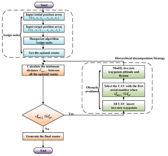
Figure 1.
Schematic diagram of the trajectory planning process for multi-UAV coordinated formation flight.
3.1. Method to Assign Tasks to Multiple UAVs in Formation Based on the Hungarian Algorithm
To enable multiple UAVs to realize the formation flight, trajectory planning according to mission objectives is the first thing to do, which is usually difficult in calculation, time-consuming in planning, and not efficient to meet actual demands. Therefore, it is important to explore a path planning algorithm with simple calculation and high efficiency for multiple UAVs.
Task assignment is of significance for multi-UAV trajectory planning, while for solving assignment problems, the Hungarian algorithm happens to be a very effective method with fast calculation and high efficiency. Therefore, this paper applies the Hungarian algorithm for the task allocation (assignment) of multiple UAVs to achieve the objective of obtaining the shortest total flight distance of all UAVs, as shown in Figure 2.
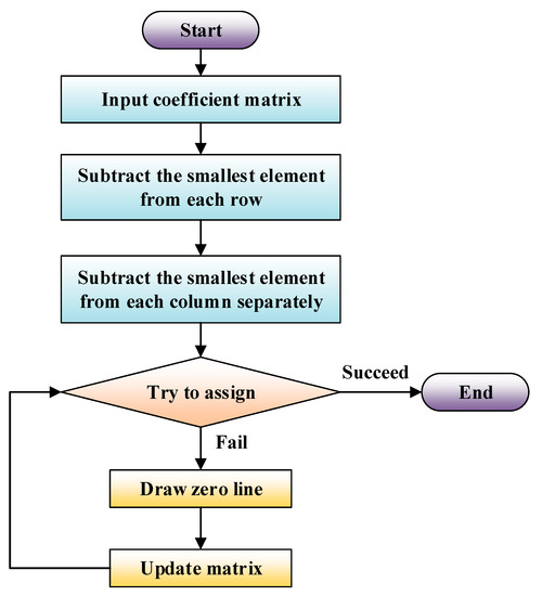
Figure 2.
Hungarian algorithm flow block diagram.
Trajectory planning for UAVs formation can be carried out based on the theorem of the optimal solution of the Hungarian algorithm. The specific steps are presented as follows:
- Step 1:
- Input the initial position matrix of UAVs and the target position matrix .
- Step 2:
- Calculate the distance between the initial position of UAVs and n target waypoints to form an distance matrix . The element represents the distance between the UAVs numbered and the target waypoint.
- Step 3:
- Apply row transformation to the distance matrix , where the smallest element of each row is subtracted from the elements of that row in matrix .
- Step 4:
- Apply column transformation to the distance matrix , where the smallest element of each column is subtracted from the elements of that column in matrix .
- Step 5:
- The trial assignment:
- (1)
- Find the row and column with the least number of zero elements without lines, that is, traverse all the zero elements without lines to check how many zeros are in rows and columns where the elements are located, and finally select the zero elements in the row and column with the least number of zero elements;
- (2)
- Find the zero elements without a line in that row and column, which is an independent zero element. Draw a line for the row and column in which those zero elements are located;
- (3)
- Leave elements covered by lines alone for the moment and repeat steps (2) and (3) until there are no lines to draw;
- (4)
- Succeed when finding independent zero elements according to the number of zero elements found in (3) and execute the next step when the number of independent zero elements is less than .
- Step 6:
- Draw a line to cover the zeros:
- (1)
- Tick rows without an independent zero element;
- (2)
- Tick the corresponding columns with one or more zero elements in the ticked rows;
- (3)
- Tick the corresponding rows with one or more independent zero elements in all ticked columns;
- (4)
- Repeat (3) and (4) until no more ticks can be made.
- Step 7:
- Update the matrix:
- (1)
- Find the smallest number among those without lines;
- (2)
- Subtract the smallest number from those without lines;
- (3)
- Add the smallest number to the numbers with two lines, ensuring that the position of zero elements remains unchanged.
- Step 8:
- Repeat steps 5–7 until success.
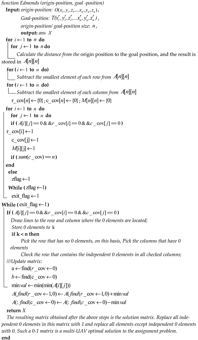
The resulting matrix obtained after the above steps is the solution matrix. Replace all the independent zero elements in this matrix with 1 and all the elements except the independent zero elements with 0. Such a 0–1 matrix is the optimal solution to the multi-UAV allocation problem.
Pseudo-code of the task allocation Algorithm 1 is:
| Algorithm 1: UAV task assignment algorithm |
 |
3.2. The Multi-UAV Trajectory Planning Method Based on the Four-Dimensional Spatiotemporal Hierarchical Decomposition
According to the task assignment result, a trajectory can be designed for each UAV from the current point to the target point, as shown in Figure 3. A collision situation would occur if the mission is executed through the trajectory. To safely complete the formation flight mission, all UAVs need to take the same time to traverse the trajectory and not collide with each other, which satisfies the time coordination and safety of the formation. Therefore, the planning of the final flight trajectory also needs to meet the time constraints and safety constraints of the UAVs’ formation based on the task assignment.
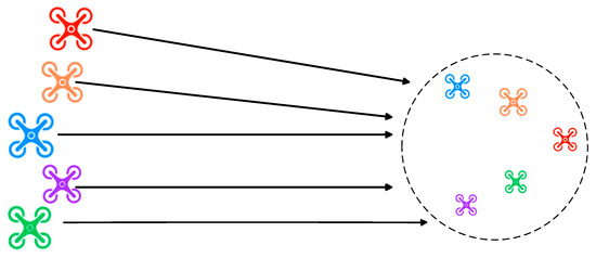
Figure 3.
Example diagram of a UAV formation.
- (1)
- Time constraints
Time constraints require all UAVs to arrive at the corresponding target point simultaneously. In the time constraint of this paper, all UAVs are required to reach the navigation point within the time constraint. In a formation mission, it is assumed in this paper that the speed of all UAVs is maintained at a certain level, and the approximate time of arrival at the target point is calculated based on the range of the UAVs to realize the cooperativeness in time for all UAVs during formation flying since each trajectory consists of a series of waypoints which do not contain accurate time information. The approximate time is employed as the benchmark to establish a time-constrained model for UAVs formation.
denotes waypoints of UAV , the total number of all waypoints of UAV ’s trajectory, the waypoint of the trajectory , the position coordinates of the trajectory, and the flight time to reach the waypoint.
Based on the above representation of a trajectory, cooperative time constraints on waypoints for a multi-UAV formation can be expressed as:
- (2)
- Safety constraints
Safety constraints require the distance between UAVs to be greater than or equal to the safety distance until they arrive at the target point to avoid collisions. Due to the large granularity of scattered waypoints, not only safety constraints at waypoints but also the safety of the entire trajectory within the same period should be determined. Specifically, and are set to represent the trajectories at the first and second waypoints of UAVs and , respectively, and the coordinates of point are set to be , point , point , and point . Safety constraints between the two UAVs are displayed in the following steps:
- Step 1:
- Set the safety distance between two UAVs to meters according to UAVs’ control accuracy and relevant external equipment;
- Step 2:
- Determine whether the shortest distance between the line segments connecting the adjacent waypoints corresponding to UAVs is less than the safe distance in a way shown as follows:
Set the line to be a point on the line . The coordinates of the point can be expressed as:
When the parameter k satisfies the condition where , is a point on the line ; when the parameter , is a point on the extended line of ; when the parameter , is a point on the extended line of .
Set the line to be a point on the line and the coordinates of the point can be expressed as:
When the parameter y satisfies the condition where , is a point on the line ; when the parameter , is a point on the extended line of ; when the parameter , is a point on the extended line of .
The distance between the point and the point is:
The squared distance is:
The shortest distance between the line and the line is the minimum value of .
Deduce the partial derivatives of for , respectively, and set the partial derivatives as 0. falls on line and falls on line , and is the shortest distance when the parameters obtained finally satisfy the condition where and . Otherwise, it will be impossible to find a point on the line and a point on the line to minimize the distance . At this point, deduce the shortest distance from to the line , and from to the line ; the shortest distance from to the line , and from to the line .
Above is the method to determine whether two trajectories collide or not, and the process of determination is presented in Figure 4.
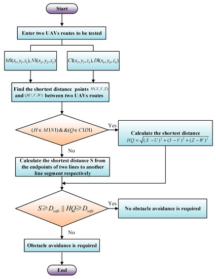
Figure 4.
Determine the trajectory collision flowchart.
A four-dimensional spatiotemporal hierarchical decomposition algorithm combined with automatic obstacle avoidance trajectory planning is proposed in this paper to meet the time constraints and safety constraints for UAVs’ formation. When the distance between UAVs is too close, the procedure of automatic obstacle avoidance takes effect and plans a route for the UAVs to avoid obstacles. Thenceforth, the UAVs will continue to perform their original tasks. Targeting the specific tasks for formations, collision detection on trajectories of all UAVs is conducted in a combination of time constraints to automatically contrive routes for obstacle avoidance in the future. The specific implementation steps are as follows:
- Step 1:
- Set the safety distance as and the time required for UAVs to fly the safety distance as ;
- Step 2:
- Step 2: Determine whether the shortest distances between the trajectory connecting the initial and target points of the first UAV and that of the remaining UAVs are greater than or equal to the safe distance s according to the initial point matrix and the target point matrix of a formation. Practice Step 3 if the shortest distance is smaller than the safe distance, and perform Step 4 if it is greater than the safe distance;
- Step 3:
- Select the smaller serial numbers of UAVs, put them into the array , and conduct Step 4;
- Step 4:
- Determine the distances between the trajectory connecting the initial and target points of the UAV and that of the remaining UAVs and repeat Step 3 until all the distances in a formation mission have been determined.
- Step 5:
- Sort the array in ascending order and copy the array to the array ;
- Step 6:
- Put all UAVs’ serial numbers in the formation mission other than those in the array into the array in ascending order;
- Step 7:
- Traverse the array , copy the position information of all UAVs’ initial and target points in the array, and at the same time increase the two points’ heights by meters, respectively. Insert the two points with increased heights into the middle of the original points (for example, the initial and target points are at and , and there will four waypoints at , , after the two new points are inserted. Count denotes the number of times to carry out step 5, which will increase by 1 each time and whose initial value is 0. Practice Step 8;
- Step 8:
- Clear the array and traverse the array to redetermine whether the distances between trajectories of all UAVs are greater than the safe distance s. Perform Step 9 after repeating steps 2 to 5;
- Step 9:
- Traverse the array and modify the altitude information of newly added UAV waypoints in the array into , , , . Count means the number of times to practice Step 5, which will increase by 1 each time and whose initial value is 0. Repeat steps 8 to 9 until the distances between UAVs in the array are greater than the safe distance;
- Step 10:
- Traverse the array G and insert two new waypoints corresponding to the nth segment of trajectories of all UAVs in the array . In this case, the original and become four waypoints of , , , ;
- Step 11:
- Clear arrays , , and , and move the positions of the initial and target points to the next section of the trajectory (for instance, set the first and the second waypoints of all UAVs as the initial and target points at the very beginning, and then take the second and the third waypoints as the initial and target points). Repeat steps 1 to 10 until the distances between trajectories of all UAVs have been checked. At this point, the algorithm ends, and multi-UAV trajectory obstacle avoidance is completed.
The schematic diagram of obstacle avoidance based on hierarchical decomposition is shown in Figure 5, where trajectories of UAV1 and UAV2 are and , respectively. There is a crossover between and , so automatic obstacle avoidance is required. According to the algorithm, UAV1 automatically inserts waypoints and , and UAV2 automatically inserts waypoints and , that is, the trajectory of UAV1 becomes ; the trajectory of UAV2 trajectory becomes . UAV1 has performed a hierarchically decomposed flight and automatically avoided obstacles.
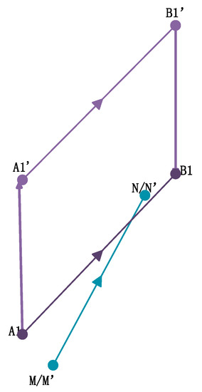
Figure 5.
Schematic diagram of hierarchical decomposition obstacle avoidance.
Pseudo-code of the hierarchical decomposition and automatic obstacle avoidance Algorithm 2:
| Algorithm 2: High layered realization of UAV obstacle avoidance |
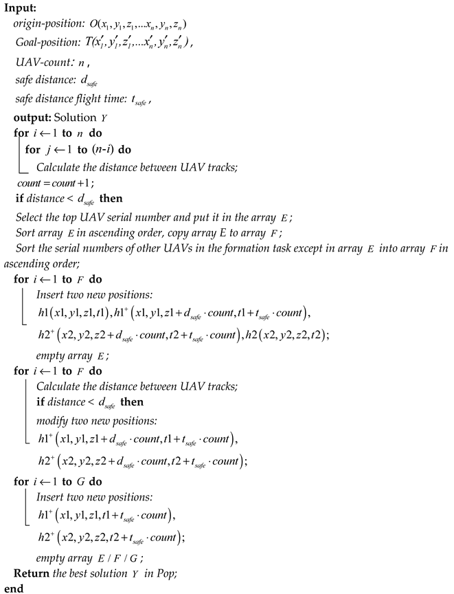 |
4. Implementation of Algorithm, Comparison, and Simulation
4.1. Formation Task Allocation Algorithm Comparison
When compared to random matching and auction algorithms is shown in Figure 6, Figure 7 and Figure 8, to make the advantages of the method proposed in this paper much clearer, for task allocation from “linear” to “circular” formation, we considered only two indicators: total trajectory length and calculation time. In order to verify the effectiveness of the algorithm, 1000 times, 10,000 times, and 100,000 times of calculations were carried out, and the results are shown in Table 1 and Table 2 below. By comparing and analyzing the data in the table, we can tell from the results that the proposed method is able to achieve the formation flight planning with the shortest total trajectory length in a comparatively shorter time.
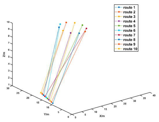
Figure 6.
Task assignment based on Hungarian algorithms.
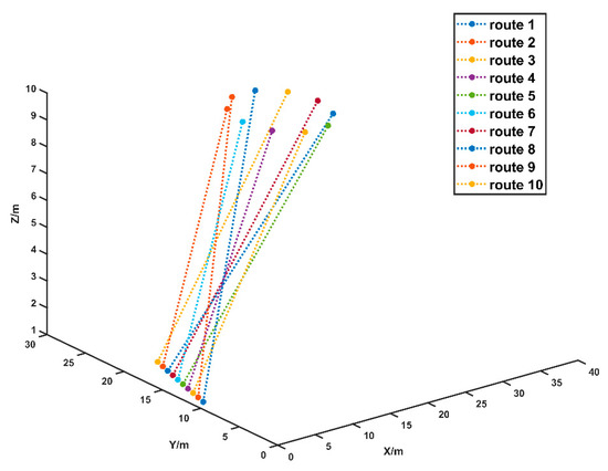
Figure 7.
Task assignment based on auction algorithms.
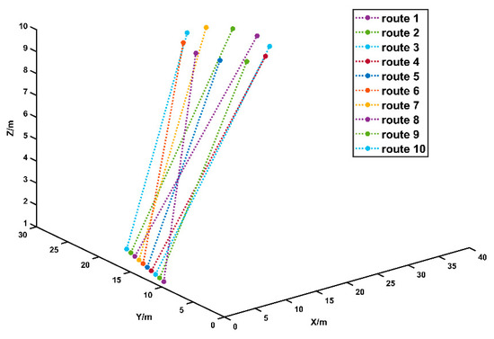
Figure 8.
Random task assignment.

Table 1.
Average total track length comparison.

Table 2.
Calculated time comparison.
4.2. Flight Simulation of Multi-UAV Formation
A simulation test of the multi-UAV formation was completed by writing relevant programs on MATLAB R2019a developed by the Mathwork company of Natick, America in the computers with the main frequency of 3.20 GHz, a memory of 32GB, and the operating system of Windows 10. To verify the effectiveness of algorithms, a formation test was conducted for 10 UAVs, and the initial and target coordinates of the 10 UAVs are shown in Figure 9:
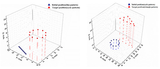
Figure 9.
Three initial positions of UAVs formation.
The following Table 3 and Table 4 demonstrates the planned trajectory with the shortest distance for 10 UAVs based on the initial and target positions, from ”one-line” to “circle” and then to “triangle”, through the Hungarian algorithm. Graphical results of the task allocation are displayed below. Row numbers of the matrix represent the UAV numbers, and column numbers are markers of the target points. A 1 element in the matrix represents that the row and the column where the 1 element is located match.

Table 3.
The “One-line” to “Circle” task assignment results.

Table 4.
The “Circle” to “Triangle” task assignment results.
Based on the results of allocation produced by the Hungarian algorithm, obstacles were avoided through the method of hierarchical decomposition after the target points were determined to ensure that all UAVs did not collide in the air. Results of obstacle avoidance are listed in the following table.
Table 5 and Table 6 shows the height hierarchy situation of the UAVs when the formation is transformed from “one-line” to “circle”, “circle” to “triangle”. Table 5 shows that the UAV 1, 5, the UAV 2, 4, 6, 9, and the UAV 3, 7, 8, 10 are at the same altitude respectively, and the times of UAV rising represents a different height. Table 5 has the same meaning as Table 6.

Table 5.
“One-line” to “circle” obstacle avoidance results.

Table 6.
“Circle” to “triangle” obstacle avoidance results.
The above results suggest that the flight altitude of UAVs with different numbers should be planned based on their different results of obstacle avoidance to avoid obstacles in the air.
Trajectory planning is carried out according to the Hungarian algorithm and the four-dimensional spatiotemporal hierarchical decomposition algorithm to realize the formation flying from a “one-line” to the shape “circle”, and from the shape of a “circle” to “triangle”. The simulation diagram is shown in Figure 10, Figure 11 and Figure 12, where line segments with the same color indicate flying on the same plane to the target points, while those with different colors imply different flight altitudes.
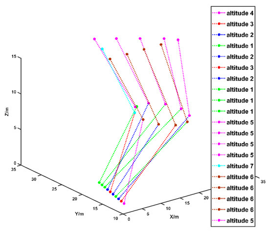
Figure 10.
Simulation of the flight of 10 unmanned aerial vehicles in formations of “one-shaped-circle-triangle”.
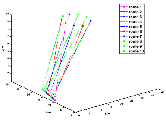
Figure 11.
Simulation of 10 UAVs “one-shaped” to “circular” formations.
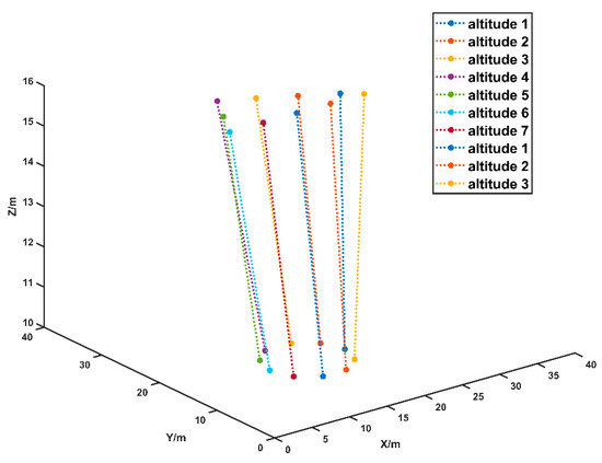
Figure 12.
Simulation of 10 UAVs flying in “circular” to “triangle” formations.
4.3. Engineering Application and Flight Test
Quadrotor UAVs were employed to complete a formation flight test in this program to verify the effectiveness and feasibility of algorithms. A quadrotor UAV is demonstrated in the following figure, made from carbon fiber materials with a fixed foldable tripod of an inverted shape, and featuring firmness and stability in Figure 13.
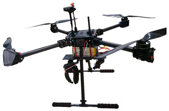
Figure 13.
Formation with quadcopter UAVs.
In the flight test, 10 UAVs were selected to complete the UAVs formation, flying in three shapes, namely a “one-line”, the shape of a “circle”, and a “triangle”. Firstly, the initial coordinates of the pattern to be formed and the final coordinates of the UAVs were entered into the simulation software program. The waypoint information of all the UAVs information were output after the program was successfully operated. The trajectory of each UAV was saved in a text file, as shown in Table 7. Then, the trajectory information of all UAVs was input into the ground station software and displayed on a map, as presented in Figure 14. Finally, the information was downloaded to the UAVs through the ground stations, and the UAVs performed the flight plan.

Table 7.
Generated information about the location of the drone 1 relative to the track point.
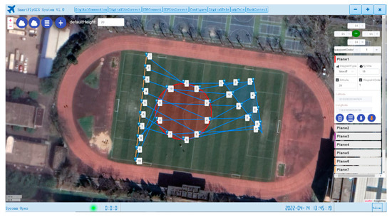
Figure 14.
Imported UAV formation map into a ground station.
In Figure 15, each card in the above diagram represents a UAV, and the status related to each UAV (including latitude and longitude information, battery voltage, and flight mode) can be observed clearly.
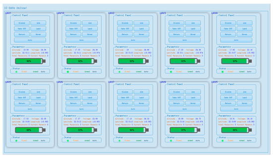
Figure 15.
Ground station 10 UAVs’ communication.
The actual formation flying of UAVs is displayed in Figure 16. During the flight, each UAV was able to arrive at a place near the designated location, and all of them could form a predetermined pattern. However, the actual positions of the UAVs formation slightly deviated from the target points due to GPS and environmental issues such as wind direction. Nevertheless, the task assigned to each UAV was accurate, and no collision occurred during the flight. Therefore, this experiment proved the feasibility of the algorithms.
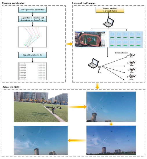
Figure 16.
Formation test flight.
5. Conclusions
Targeting three-dimensional space trajectory planning for multi-UAV in cooperative formation, the Hungarian algorithm is adopted in this paper based on formation control under the virtual pilot to minimize costs of the total distance of trajectories during formation transformations, and a four-dimensional spatiotemporal hierarchical decomposition strategy on flight altitude is put forward to avoid collisions during formation flying. This method combines the Hungarian algorithm with the hierarchical decomposition strategy, which is of significantly better efficiency and can plan the optimal trajectory in only a few hundred milliseconds. Compared with the auction algorithm, the total track distance and planning time are reduced by about 3%. Meanwhile, time constraints of the UAVs’ formation flying are combined to preplan a route for automatic obstacle avoidance without other communication between UAVs. In the end, verification is conducted through MATLAB simulation and test, and 10 UAVs formation have realized shape transformation from a “one-line” to a “circle”, and then to a “triangle”. Tested in actual flight, each UAV can reach the corresponding destination quickly and without collision, thus verifying the effectiveness and reliability of this method stated in the paper.
Author Contributions
Conceptualization, J.Z.; Methodology, H.S.; Validation, Q.C.; Formal analysis, B.Y.; Investigation, H.Z.; Data curation, J.L.; Writing—original draft preparation, J.Z.; Writing—review and editing, M.L.; Supervision, H.S. All authors have read and agreed to the published version of the manuscript.
Funding
This work is supported by Funding from the National Key Laboratory of Rotorcraft Aeromechanics (No. 61422202108), and the National Natural Science Foundation of China (No.51906103, No.52176009).
Data Availability Statement
The data presented in this study are available on request from the corresponding author.
Conflicts of Interest
The authors declare no conflict of interest. The funders had no role in the design of the study; in the collection, analyses, or interpretation of data; in the writing of the manuscript, or in the decision to publish the results.
Nomenclature
| distance matrix | |
| = | distance between the UAV number and the target waypoint j |
| = | drone waypoint |
| = | drone track |
| = | drone waypoint |
| = | number of waypoint modifications |
| = | line segment |
| = | line segment C1D1 and M1N1 endpoints |
| = | UAVs’ initial waypoints to target waypoints route distance matrix |
| = | safe distance between UAVs |
| = | minimum distance between two routes |
| = | serial number array of UAV whose route distance is less than the safe distance |
| = | an ascending array of drone serial numbers |
| = | serial number array of UAV whose route distance is greater than the safe distance |
| = | two waypoints |
| = | new waypoints |
| = | line intersection |
| = | serial number of array or matrix |
| = | slope of a line |
| = | UAVs’ initial waypoints to target waypoints route matrix |
| = | line segment |
| = | drone track |
| = | drone waypoint |
| = | drone waypoint |
| = | number of UAV |
| = | UAVs’ initial waypoints matrix |
| = | the i-th waypoint information of the UAVs |
| = | UAVs’ target waypoints matrix |
| = | flight time to the i-th waypoint |
| = | time required to fly distance |
| = | point coordinates |
| = | intersection coordinates |
| = | intersection coordinates |
References
- Tong, H.; Andi, T.; Huan, Z.; Dengwu, X.; Lei, X. Multiple UAV cooperative path planning based on LASSA method. Syst. Eng. Electron. 2022, 44, 233–241. [Google Scholar]
- Ni, J.; Tang, G.; Mo, Z.; Cao, W.; Yang, S.X. An improved potential game theory based method for multi-UAV cooperative search. IEEE Access 2020, 8, 47787–47796. [Google Scholar] [CrossRef]
- Wu, W.; Wang, X.; Cui, N. Fast and coupled solution for cooperative mission planning of multiple heterogeneous unmanned aerial vehicles. Aerosp. Sci. Technol. 2018, 79, 131–144. [Google Scholar] [CrossRef]
- Liscouët, J.; Pollet, F.; Jézégou, J.; Budinger, M.; Delbecq, S.; Moschetta, J.M. A methodology to integrate reliability into the conceptual design of safety-critical multirotor unmanned aerial vehicles. Aerosp. Sci. Technol. 2022, 127, 107681. [Google Scholar] [CrossRef]
- Causa, F.; Fasano, G. Multiple UAVs trajectory generation and waypoint assignment in urban environment based on DOP maps. Aerosp. Sci. Technol. 2021, 110, 106507. [Google Scholar] [CrossRef]
- Zhu, Z.; Qian, Y.; Zhang, W. Research on UAV Searching Path Planning Based on Improved Ant Colony Optimization Algorithm. In Proceedings of the 2021 IEEE 3rd International Conference on Civil Aviation Safety and Information Technology (ICCASIT), Changsha, China, 20–22 October 2021; IEEE: Piscataway, NJ, USA, 2021; pp. 1319–1323. [Google Scholar]
- Mokrane, A.; Braham, A.C.; Cherki, B. UAV path planning based on dynamic programming algorithm on photogrammetric DEMs. In Proceedings of the 2020 International Conference on Electrical Engineering (ICEE), Istanbul, Turkey, 25–27 September 2020; IEEE: Piscataway, NJ, USA, 2021; pp. 1–5. [Google Scholar]
- Wu, X.; Xu, L.; Zhen, R.; Wu, X. Biased sampling potentially guided intelligent bidirectional RRT* algorithm for UAV path planning in 3D environment. Math. Probl. Eng. 2019, 2019, 5157403. [Google Scholar] [CrossRef]
- Huang, J.; Sun, W. A method of feasible trajectory planning for UAV formation based on bi-directional fast search tree. Optik 2020, 221, 165213. [Google Scholar] [CrossRef]
- Junlan, N.; Qingjie, Z.; Yanfen, W. UAV path planning based on weighted-Voronoi diagram. Flight Dyn. 2015, 33, 339–343. [Google Scholar]
- Chen, X.; Chen, X. The UAV dynamic path planning algorithm research based on Voronoi diagram. In Proceedings of the 26th Chinese Control and Decision Conference (2014 CCDC), Changsha, China, 31 May–2 June 2014; IEEE: Piscataway, NJ, USA, 2014; pp. 1069–1071. [Google Scholar]
- Mandloi, D.; Arya, R.; Verma, A.K. Unmanned aerial vehicle path planning based on A* algorithm and its variants in 3d environment. Int. J. Syst. Assur. Eng. Manag. 2021, 12, 990–1000. [Google Scholar] [CrossRef]
- Cheng, N.; Liu, Z.; Li, Y. Path Planning Algorithm of Dijkstra-Based Intelligent Aircraft under Multiple Constraints. Xibei Gongye Daxue Xuebao/J. Northwest. Polytech. Univ. 2020, 38, 1284–1290. [Google Scholar] [CrossRef]
- Yuan, G.; Xia, J.; Duan, H. A continuous modeling method via improved pigeon-inspired optimization for wake vortices in UAVs close formation flight. Aerosp. Sci. Technol. 2022, 120, 107259. [Google Scholar] [CrossRef]
- Chai, X.; Zheng, Z.; Xiao, J.; Yan, L.; Qu, B.; Wen, P.; Wang, H.; Zhou, Y.; Sun, H. Multi-Strategy Fusion Differential Evolution Algorithm for UAV Path Planning in Complex Environment. Aerosp. Sci. Technol. 2021, 121, 107287. [Google Scholar] [CrossRef]
- Xianqiang, L.I.; Rong, M.A.; Zhang, S. Improved design of ant colony algorithm and its application in path planning. Acta Aeronaut. Astronaut. Sin. 2020, 41, 724381. [Google Scholar]
- Liu, Y.; Zhang, X.; Guan, X.; Delahaye, D. Adaptive sensitivity decision based path planning algorithm for unmanned aerial vehicle with improved particle swarm optimization. Aerosp. Sci. Technol. 2016, 58, 92–102. [Google Scholar] [CrossRef]
- Jiang, T.; Li, J.; Huang, K. Longitudinal parameter identification of a small unmanned aerial vehicle based on modified particle swarm optimization. Chin. J. Aeronaut. 2015, 28, 865–873. [Google Scholar] [CrossRef]
- Su, Y.; Dai, Y.; Liu, Y. A hybrid hyper-heuristic whale optimization algorithm for reusable launch vehicle reentry trajectory optimization. Aerosp. Sci. Technol. 2021, 119, 107200. [Google Scholar] [CrossRef]
- Miao, H.; Tian, Y.C. Dynamic robot path planning using an enhanced simulated annealing approach. Appl. Math. Comput. 2013, 222, 420–437. [Google Scholar] [CrossRef]
- Ji-yang, D.; Cun-song, W.; Lin-fei, Y.; Bao-jian, Y.; Jun-qiang, X. Hierarchical potential field algorithm of path planning for aircraft. Control Theory Appl. 2015, 32, 1505–1510. [Google Scholar]
- Wenzhao, S.; Naigang, C.; Bei, H.; Xiaogang, W.; Yuliang, B. Multiple UAV cooperative path planning based on PSO-HJ method. J. Chin. Inert. Technol. 2020, 28, 122–128. [Google Scholar]
- Wu, Y.; Gou, J.; Hu, X.; Huang, Y. A new consensus theory-based method for formation control and obstacle avoidance of UAVs. Aerosp. Sci. Technol. 2020, 107, 106332. [Google Scholar] [CrossRef]
- Yu, J.; Dong, X.; Li, Q.; Ren, Z. Practical time-varying output formation tracking for high-order multi-agent systems with collision avoidance, obstacle dodging and connectivity maintenance. J. Frankl. Inst. 2019, 356, 5898–5926. [Google Scholar] [CrossRef]
Publisher’s Note: MDPI stays neutral with regard to jurisdictional claims in published maps and institutional affiliations. |
© 2022 by the authors. Licensee MDPI, Basel, Switzerland. This article is an open access article distributed under the terms and conditions of the Creative Commons Attribution (CC BY) license (https://creativecommons.org/licenses/by/4.0/).