Article

Aerial Torsional Work Utilizing a Multirotor UAV with Add-on Thrust Vectoring Device

by
Ricardo Rosales Martinez
1,*,
Hannibal Paul
2 and
Kazuhiro Shimonomura
1
1
Department of Robotics, Graduate School of Science and Engineering, Ritsumeikan University, Kusatsu 525-8577, Japan
2
Research Organization of Science and Technology, Ritsumeikan University, Kusatsu 525-8577, Japan
*
Author to whom correspondence should be addressed.
Drones 2023, 7(9), 551; https://doi.org/10.3390/drones7090551
Submission received: 31 July 2023 / Revised: 19 August 2023 / Accepted: 22 August 2023 / Published: 25 August 2023
(This article belongs to the Special Issue Drones: Opportunities and Challenges)

Abstract

:
Aerial manipulation aims to combine the versatility and the agility of aerial platforms with the manipulation capabilities of robotic arms. Their fast deployment allows for their implementation in maintenance tasks and support during disaster situations. However, the under-actuated nature of multirotor UAVs limits the magnitude and direction of the forces an aerial vehicle can safely exert during manipulation tasks. In this paper, the problems associated with UAVs and torsional tasks constraints regarding valve turning are addressed. An add-on thrust vectoring device which enhances manipulation options available to a conventional multirotor UAV is developed and described. The proposed system allows for a partial decoupling of the attitude and velocity vector of a multirotor. This permits stable translational flight and higher torque capabilities for torsional tasks. The separation of attitude and the velocity vector that allows for the design of a passive mechanism for valve operation is presented in this paper as well. The experimental results illustrate the forces and torques that can be generated in the evaluated operation modes.

1. Introduction

The field of aerial manipulation is growing with an increasing number of interesting and versatile aerial manipulator designs [1,2]. However, physical interactions with the environment require special considerations, since unmanned aerial vehicles (UAVs) must compensate for the contact forces present during manipulation. Among these types of interactions, torsional tasks are of great interest, since they allow for applications such as the replacement of light bulbs [3] at different altitudes, loosening/fastening nuts [4], material drilling/sampling, and valve manipulation [5,6,7,8,9,10,11,12,13,14]. The safe operation of valves is necessary in a variety of industrial and civil infrastructure applications, including the operation of water distribution systems, the safe regulation of pressurized gasses, and the control of flammable or toxic chemicals. Besides maintenance tasks, during disaster situations, critical tasks must be carried on in order to reduce the level of danger, e.g., regulating combustible substances or water supply systems for fire protection [15]. If valves are manually operated, this exposes human operators to a variety of life threatening hazards. This is one of the reasons why valve operation methods have been widely studied in different areas of robotics, from unmanned ground vehicles (UVGs) [5], humanoid robots [6,7,8,9], UAVs [10,11,12,13], and autonomous underwater vehicles (AUVs) [14]. Each type of system has its strengths and limitation based on how the robot interacts with the environment and reacts to the contact forces required during manipulation. The use of UAVs is especially advantageous for valves located in high or inaccessible locations.
In this paper, we propose a multirotor UAV-based aerial torsional work by proposing an add-on thrust vectoring device, which can generate a torque large enough to operate industrial valves. This capability of torsional work is experimentally evaluated with the manipulation of a real industrial valve from its closed state. The system generates the required torque, by landing on valve, disarming the UAV’s propellers, and utilizing the forces generated by the thrust vectoring device. With the previous research in [16] we showed the effectiveness of an add-on thruster system for UAVs, which generated horizontal forces independent from the multirotor UAV’s propellers. However, due to the fixed configuration and orientation of the additional actuators, the use of this system was limited to translational movement. The system proposed in this study allows for the change between the two operation modes, translational flight mode and torsional work on a valve, as shown in Figure 1. The main contributions of this paper are summarized as follows:
  • The presentation of the mechanical design of a add-on thrust vectoring system for torsional work.
  • The design and evaluation of a passive landing mechanism for valve manipulation.
  • The modeling and control allocation of the aerial platform in its general case and its transition between modes.
  • The evaluation of the torque capabilities of the system in real life experiments from flight to the operation of an industrial grade valve.

2. Valve Turning Problem and Design Constraints

Valves are often positioned in strategically chosen locations, based on their target application and considerations for ease of access [17,18]. In the field of robotics, when examining the valve turning task, we must consider the following characteristics:
1.
Valve’s location and orientation;
2.
Fastening/gripping method;
3.
Torque source and control of the manipulator.
The location and orientation determines the way a robotic system must approach the object of interest, as well as limiting its possible use scenarios. Their orientation refers to the manner in which they are installed, i.e., the direction of their pipes or fittings, most commonly horizontal (upward facing) and vertical valves (side facing). This spatial information as well as the valve’s dimensions dictates the design of viable grasping and fastening methods and the nature of the used manipulator. Once the valve has been grasped, the type of robotic system (e.g., UGVs, UAVs) will provide, through its available actuators and body dynamics, the necessary torque for the operation. The actuators and the design of the manipulators will determine the available torque range. In addition the operation time is dependent on the rotational rate at the which the system is capable of turning the valve. When compared with other robotics systems, the main advantage of UAVs are their ease of movement, which allows for a quick travel to areas of interest. Although often used for the purpose of inspection, there have been proposals [10,11,12,13] to solve torsional tasks with UAVs. In most of these cases the aerial systems focus on valves with a horizontal orientation, which allows the object of interest to be positioned below the airframe. This type of interaction present problems unique to aerial manipulators, since UAVs must remain in a stable flight state during the manipulation. Hence, most of the previous research have relied on the use of complex manipulators to grasp and turn the valve. Such designs must consider the effects of the manipulation, i.e, the contact forces present during the operation. During the grasping operation the manipulator couples the UAV dynamics to the manipulation task. Aerial systems often require control strategies to mitigate these instabilities, thus limiting the system to low torque magnitudes and slow rotation rates. Ramon-Soria et al. in [11] developed a dual arm UAV which allows for a compliant fastening method. The valve is actuated through the reaction torque generated by the propellers of the UAV. In [12], two UAVs are joined in a chain manipulation arrangement, where the fastening method is located in between the two UAVs. The system uses the thrust vector of each unit to generate the torque, while the fastening method is being controlled by an electromagnet. Hybrid methods have been also proposed as in the case of [9], in which a set of propellers generate the motion of each link in a manipulation chain. This configuration allows for the generation of torque in a direction which allows for the rotation of a horizontal valve, by acting through its spokes. This idea is further expanded on in [13], where a complex articulated aerial platform operates both horizontal and vertical valves, by changing the position of each of its links.

Thrust and Torque Relation

UAVs’ torque capabilities depend on the nature of their propellers, and the effect of the thrust produced. The orientation of the propellers on a flying platform has a direct relation with its resultant thrust magnitude and orientation and how this force actuates upon the platform. This relation also conditions the rotational rate which in turn affects the total operation time. Most multirotors can be grouped in the following categories:
  • Collinearly oriented propellers (COP): All the propellers have the same orientation, thus their resultant thrust vectors points in the same direction.
  • Non-collinearly oriented propellers (NCOP): One or more than one of the propellers are positioned in different orientations, having their resultant thrust vectors pointing at different directions.
Most commercial multirotor systems follow the COP configuration, which is characterized by their under-actuated nature, where the thrust generated by the propellers must create a turning moment to change its attitude. By controlling this attitude change the system can direct the thrust force in the direction of the desired motion. This situation causes the attitude and position of the vehicle to be coupled, which also limits the magnitude and orientation of the forces available for manipulation tasks. For torsional tasks below or above the airframe, the torque along the Z axis (upwards), which corresponds to the yaw motion of the UAV, is described by Equation (1). In order to increase the available torque, the speed of the propellers must be increased proportionately, to reach the desired rotational torque and maintain their position. UAVs must then, through manipulators, operate on a valve while maintaining a stable flight. For conventional multirotor UAVs, the yaw rotation only produces low magnitude torque values. Usually, multirotor UAVs will not be capable of operating industrial size valves, due to their low generated torque. In order to deal with this limitation and obtain higher torque magnitudes, motors, propellers and the airframe size must be increased in dimensions. This presents two scenarios regarding the maximum available torque that can be generated during operation. If the system is limited to stay in the hover state, then the maximum torque is bounded to the total thrust equivalent to the weight of the UAV. The yaw rotation of multirotors is generated by strategically changing the angular velocity of the motors and in turn controlling their individual moments. In order to obtain the theoretical maximum torque possible by the actuators, the set of motors responsible for the rotation would need to increase their angular velocity exceeding the hover state condition, which would result in an upward force. This second scenario imposes additional requirements for the manipulator, which must grasp and fasten itself to the valve but also counter the upward force, generated by the thrust, which pulls away from the valve during operation.
T i = μ ω i 2 τ z = n = 1 N f i k i
NCOP systems offer alternative methods that can provide both stability and precision for more specialized tasks. Configurations such as this allow the vehicle to have full force and torque authority by enabling the control of the direction and magnitude of the applied thrust. In [19], an omnidirectional UAV composed of eight fixed propellers located around its frame, is capable of generating both direct and reverse thrust. Alternatively, designing systems with additional degrees-of-freedom (DOFs) in the rotors of the vehicle has shown great promise for aerial manipulation tasks [20,21,22,23,24]. These vehicles present designs with tilting rotors, which enable the control of the direction and magnitude of the applied thrust. Based on the previous strategies, the required torsional force can be more efficiently produced. Instead of being dependent on the aerodynamic drag, the torque can be directly generated by the thrust vector. Based on the aforementioned valve manipulation constraints and thrust/torque considerations, the following the observations can be drawn:
1.
Torsional work on objects located above and below the airframe such as horizontal valves [10,11,12,13] often rely on the UAV’s yaw, but are limited to low torsional magnitudes. To solve this situation other methods use custom frames such as non-collinearly oriented propeller (NCOP) systems, which are able to produce higher torque magnitudes as shown in [9,12].
2.
As shown in [9,12,13] coming into contact with the valve’s spoke is sufficient to properly operate it. This method reduce the complexity of the grasping strategy and also can be applied to different valve orientations.
3.
Vertical valves present their own particular set of challenges due to their axis of rotation with respect to the UAV. Although collinearly oriented propeller (COP) multirotors can produce higher torsional magnitudes in their pitch and roll rotations. These torques are coupled to the movement and flight of the UAV, which complicates their use for valve manipulation tasks.
The aerial manipulation system presented in this research addresses observations (1) and (2). This design focuses on the manipulation of horizontal valves, below the airframe of the UAV and the application of the turning force on the valve’s spokes. Observation (3), which refers to the manipulation of vertical valves, is beyond the scope of the current research, and will be presented in a future paper.

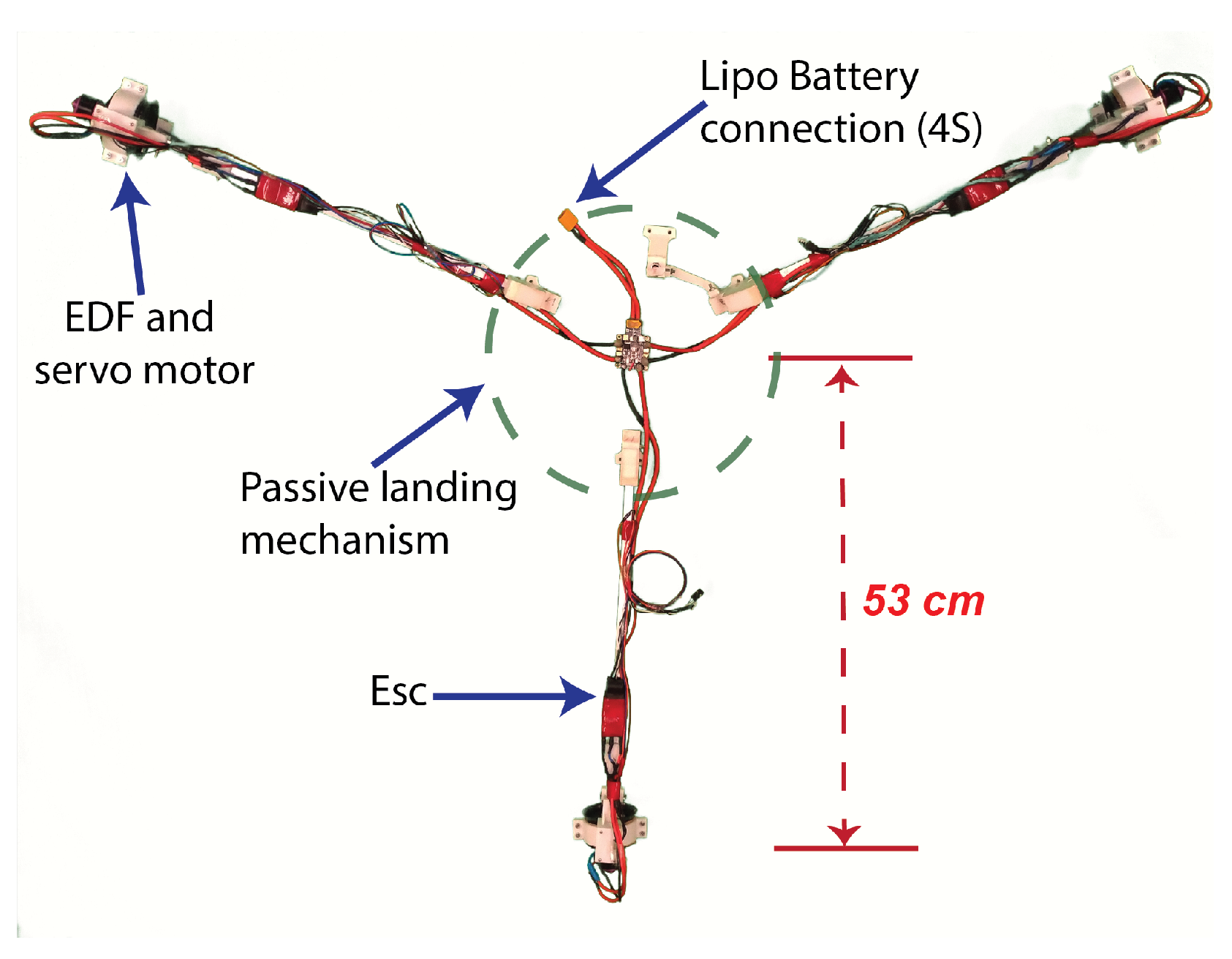
3. System Description

In this study, our previous research in [16] has been enhanced with thrust vectoring capabilities. The original system allowed for a commercial UAV to move in a planar motion, i.e., without changing the pitch and roll of its frame. The additional thrust vectors generated by electric ducted fans (EDFs) increased the available forces the multirotor could initially exert. This in turn allowed the UAV to no longer be limited by the the direction of the propellers thrust vector. Besides increasing the range of motion of the multirotor, the resultant force from the add-on device generates planar forces for pushing and pulling tasks, while providing a stable platform during the operations. The designs objectives were that the proposed system had to be capable of generating high torque in both directions while maintaining the operation properties of our previous research. Omnidirectional UAVs present a possible solution to these design objectives. Although these systems can expand the manipulation capabilities of (COP) multirotors, such improvements also increase the complexity of their design and control. Many manipulation tasks benefit from aspects of these systems but don’t require all their control capabilities. Our proposed solution provides a good compromise, where it is capable of enhancing the manipulation and movement options of conventional multirotors, without the added complexity inherent in omnidirectional systems. The tested configurations included the transition from a the normal flight mode, a planar translational mode were roll and pitch are limited to be close to 0°, and a torsional configuration.
The specifications of the thrust vectoring device and its components are listed in Table 1. The system is composed of three EDFs each positioned at a distance of 53 cm from the center of the multirotor and at a separation of 120° from each other as shown in Figure 2. Each EDF is actuated by a servomotor with its rotation axis perpendicular to its thrust vector. The additional degree of freedom allows the thrust direction of each of the fans to be controlled independently.
The add-on device is mounted below an off-the-shelf hexarotor platform, as shown in Figure 3, with a propulsion system controlled by a DJI N3 flight controller. As shown in Figure 4 the tele-operator communicates remotely with the UAV, through the receiver connected to the flight controller. A three position switch in the remote controller (RC) is used as the mode selection channel, which allows the operator to select between the three operation modes of the system. The selected operation mode, determines the way the left and right stick of the RC command the UAV’s movement. In the normal flight mode, these channels correspond to the altitude, roll, pitch, and yaw rates of the UAV. In the translational mode, the channels control the altitude, planar positioning, and yaw of the system. An on-board CPU, LattePanda Alpha 864, controls and monitor the flight controller information and the thrust vectoring system. The operating system installed in the on-board CPU is Ubuntu 16.04 with the ROS Kinetic distribution. The ROS environment serves as the communication bridge between the flight controller, the position estimation block, and the thrust vectoring system controller. The DJI Onboard SDK block corresponds to the ROS implementation of the serial link between the flight controller and the on-board CPU. This allows for the on-board CPU to communicate with the flight controller, obtaining IMU data, the RC channels input signal, and sending attitude commands to the UAV during the translational operation mode. A realsense T265 stereo tracking camera module, mounted in the front of the unit (front facing), provides the system with its position and velocity estimate. The Intel RealSense ROS wrapper package allows the tracking camera to be accessed by the other components of the system. This position data in conjunction with the attitude information of the flight controller, make up the the position estimation block. The revised position estimation data, and the commands from the tele-operator are then sent to the thrust vectoring controller. This control block is responsible for controlling the direction and magnitude of the thrust vectors, according to the selected operation mode, tele-operator commands, and the state estimation information. The joint angle node obtains the desired angles θ 1 ,   θ 2 ,   θ 3 , and these are sent to the corresponding servo motors by the I2C protocol. Likewise, the fan speed node reads the required angular velocities ω 1 ,   ω 2 ,   ω 3 , and these are converted to PWM signals to control the thrust force of each EDF.

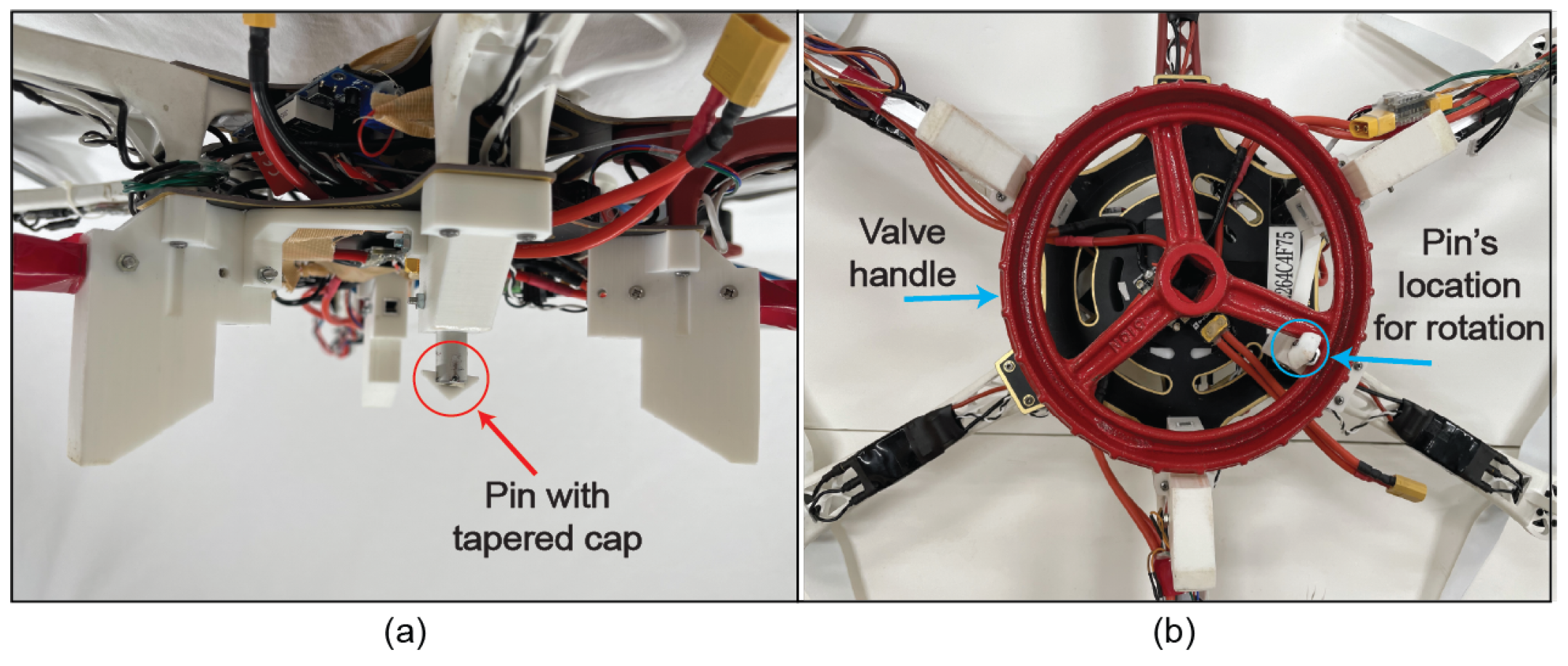
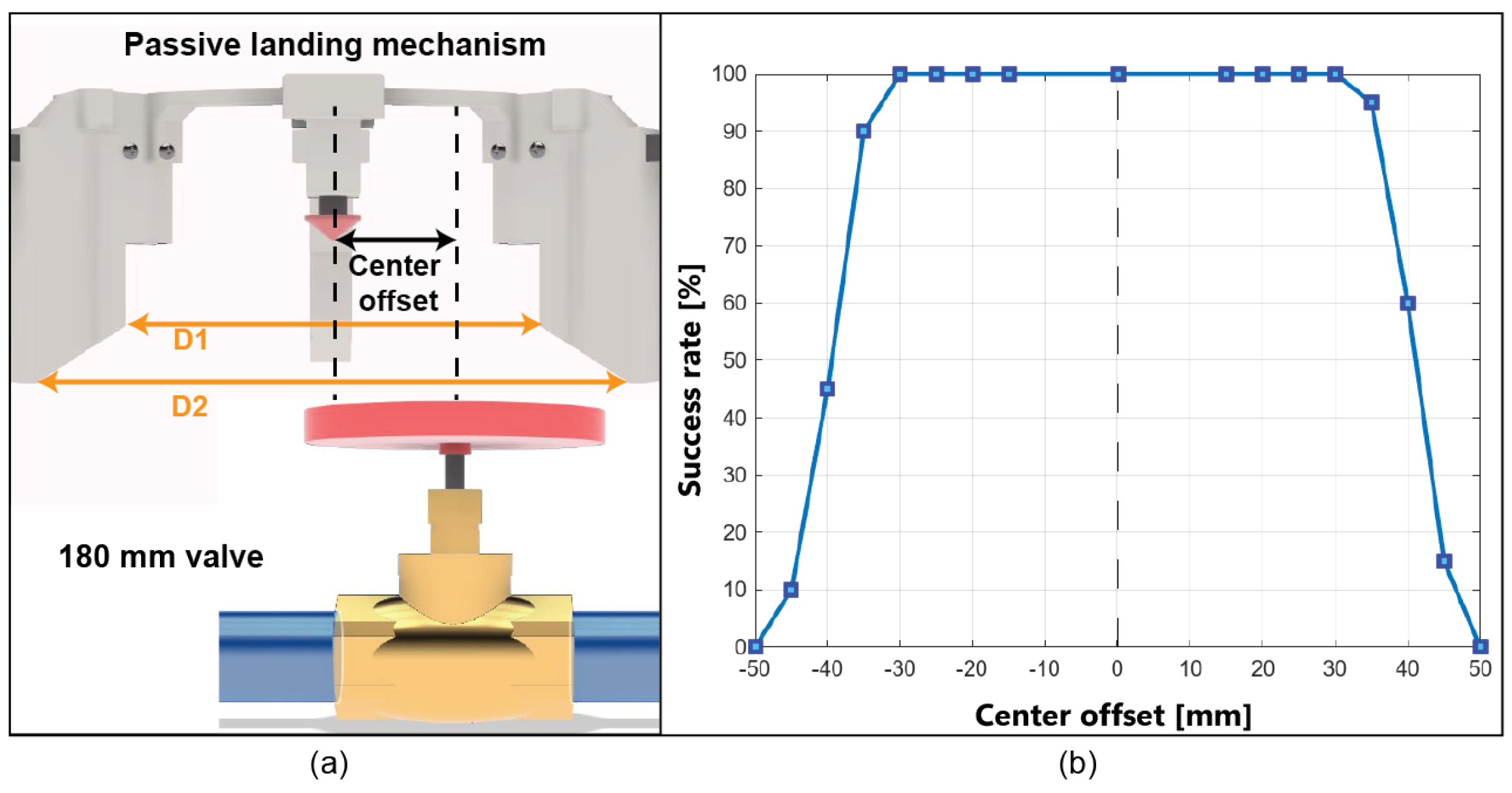
4. Passive Landing Mechanism

The decoupling of the torque generated by the EDFs and the propeller’s thrust has several consequences: First, the system is not confined to be in-flight in order to generate a torsional moment. This permits the multirotor to land on a horizontal valve and disarm its propellers, while operating in a more stable workspace. Moreover, the landed state reduces the complexity of the required mechanism and removes the previously mentioned force coupling problem. Because during the operation the multirotor is no longer flying and the thrust of the EDFs are perpendicular to the rotation axis of the valve, the mechanism is not required to fasten or grip the valve due to the lack of an upward force. Figure 5 shows the proposed valve turning mechanism, which is designed for round-shaped handle valves.
Three 3D printed accessories, located at a separation of 120° from each other, make up the structure of the passive landing mechanism. As the multirotor approaches the valve, it is passively guided to its center by the cone shape of the mechanism. The innermost diameter of the mechanism D1 has a dimension of 182 mm, whereas the outermost diameter D2 is 250 mm. Based on this characteristic, the passive landing mechanism self centers the multirotor as it approaches the valve, where the maximum diameter is larger than that of the valve’s external diameter. This error allowance reduces the difficulty when approaching the object of interest. The outer rim of the valve acts as a landing support, fixing the system in place for the rotational task. As shown in Figure 5b, inside the valve’s landing mechanism, a pin with a tapered cap in the innermost diameter is used to interact with the valve spokes. By exerting forces directly in the spokes, the mechanism is able to operate the valve, whereas the EDFs generate the required torque. In a landing scenario where the pin lands directly on top of a spoke, the tapered cap slides the pin to its correct position. The pin is held in place by a 3D printed base attachment which is fixed to the base of frame of the UAV. Since the force that turns the valve is transmitted by the contact of the pin and the valve’s spoke, a support brace is positioned to the side of the pin’s base attachment. This improves the force distribution and reduces the possibility of the pin being detached from the mechanism during the torsional task. The current design is optimized for the industrial JIS valve handle standard, but by changing the position of the pin or increasing their quantity, the mechanism can be used for turning different valve sizes and shapes. In the case of valves with an outer diameter smaller than 180 mm, the pin has to be positioned closer to the center of the landing mechanism in order to allow contact with the internal spokes. Conversely, if the valve’s diameter is larger than 180 mm, the 3D printed guiding components of the cone shaped mechanism have to be placed farther away from the center, increasing both D1 and D2.

Passive Landing Mechanism Tolerance

The first experiment consisted of a drop test to evaluate the effectiveness of the passive landing mechanism, when approaching the valve at different offsets from the center, as shown in Figure 6. The positive offset corresponds to the approach from the left direction of the dotted line, where two of the accessories come first into contact with the valve. Conversely, the negative offset approaches from the right direction and only one accessory comes into initial direct contact with the valve. The experiment consisted of 20 attempts at different distances with 5 mm of separation. It can be observed that at an offset of ±35 mm the system is capable of safely landing in the valve. As the offset increase beyond this point, the success rate decreases. However, the positive approach from the left tends to be safer, since in this area two accessories are in contact with the valve, guiding the UAV to the center of the valve from two different radial directions. In contrast the negative approach with the same offset, guides the system but fails to center it.

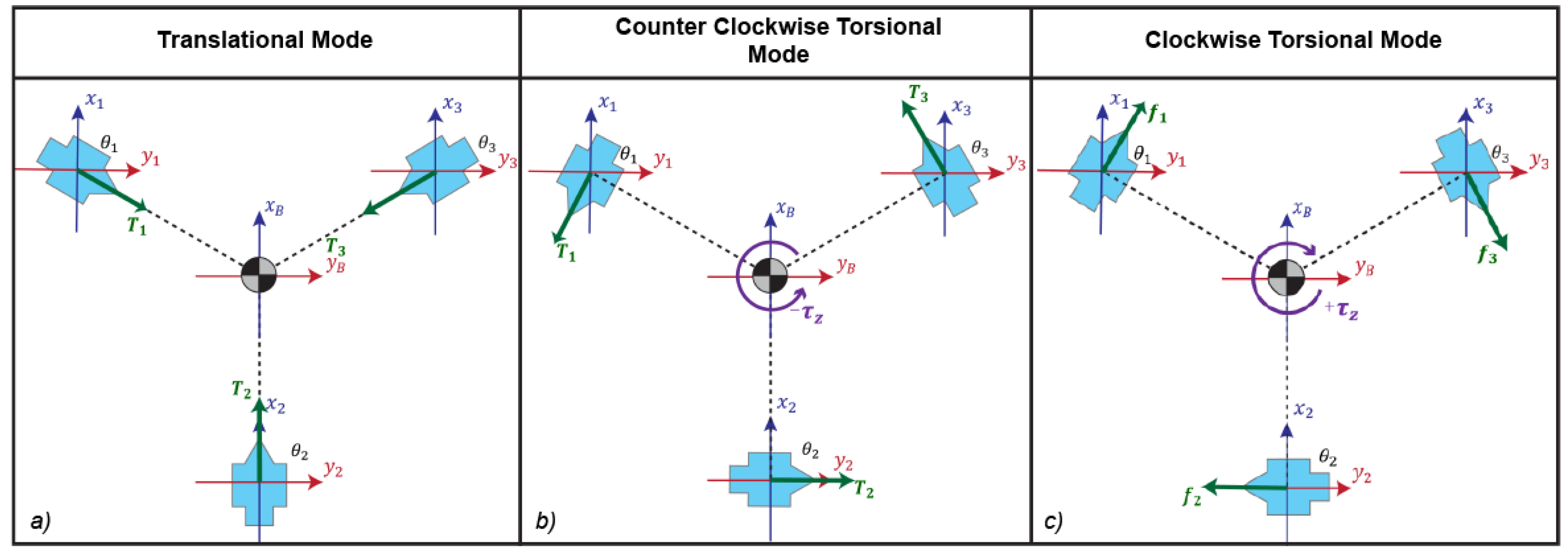
5. Thrust Vectoring Control Framework

The thrust vectoring device requires the multirotor system to be in its hover state. This refers to the state during flight where the total thrust force exerted by the propellers of the multirotor are of equal magnitude and opposite direction to the total weight of the system. Under this equilibrium condition the control of the platform can be reduced to the actuators and EDFs of the add-on device, excluding the propellers of the multirotor from its modeling.
F M = A ( Θ ) · Ω A R 5 × 3
Figure 7 shows the coordinate frames used for the modeling of the system and Table 2 refers to the notation used. The origin is positioned at the center of gravity (CoG) of the aerial platform, where the body frame is located. In this convention the z axis points downward, with a clockwise (CW) rotation corresponding to a positive torque, and a counterclockwise (CCW) to a negative. Each EDF has its respective coordinate frame fixed to its center of rotation, the x and y axes are aligned to the body frame. The geometric arrangement of the propulsion system determines the effects of the aerodynamic forces and drag moments present in the CoG of the aerial platform. This relation defines the control allocation problem, which provides the transformation of the desired forces and moments of the aerial system to the individual motor commands of the EDFs. The general case refers to the problem of solving for both EDFs angular velocities ω 1 ,   ω 2 ,   ω 3 and the angular positions θ 1 ,   θ 2 ,   θ 3 which satisfy Equation (2). The control allocation matrix for the system is shown in its expanded form in Equation (3).
f x f y τ x τ y τ z = μ C 1 μ C 2 μ C 3 μ S 1 μ S 2 μ S 3 k C 1 k C 2 k C 3 k S 1 k S 2 k S 3 d x 1 ( μ S 1 ) + d y 1 ( μ C 1 ) d x 2 ( μ S 2 ) d x 3 ( μ S 3 ) d y 3 ( μ C 3 ) · ω 1 2 ω 2 2 ω 3 2
The moments τ x , τ y , which depend on the aerodynamic drag k, are of significantly lower magnitudes. Therefore, they have negligible effects in the UAV, when compared to the moments produced by the rest of the actuators. As such, this moments can be expressed as
τ x , τ y 0
With this consideration, Equation (3), can be simplified to the following,
f x f y τ z = μ C 1 μ C 2 μ C 3 μ S 1 μ S 2 μ S 3 d x 1 ( μ S 1 ) + d y 1 ( μ C 1 ) d x 2 ( μ S 2 ) d x 3 ( μ S 3 ) d y 3 ( μ C 3 ) · ω 1 2 ω 2 2 ω 3 2
When solving for the desired forces and moments, this configuration of actuators produces a non-linear mapping for the angular velocities Ω and the angular position Θ vectors. However, the operation modes evaluated in this research correspond to three different Θ configurations, the desired joint angles are known. This causes the matrix A ( Θ ) to be constant reducing the complexity of the control allocation problem, where only the squared angular velocities Ω need to be solved for. This special configurations include the following:
1.
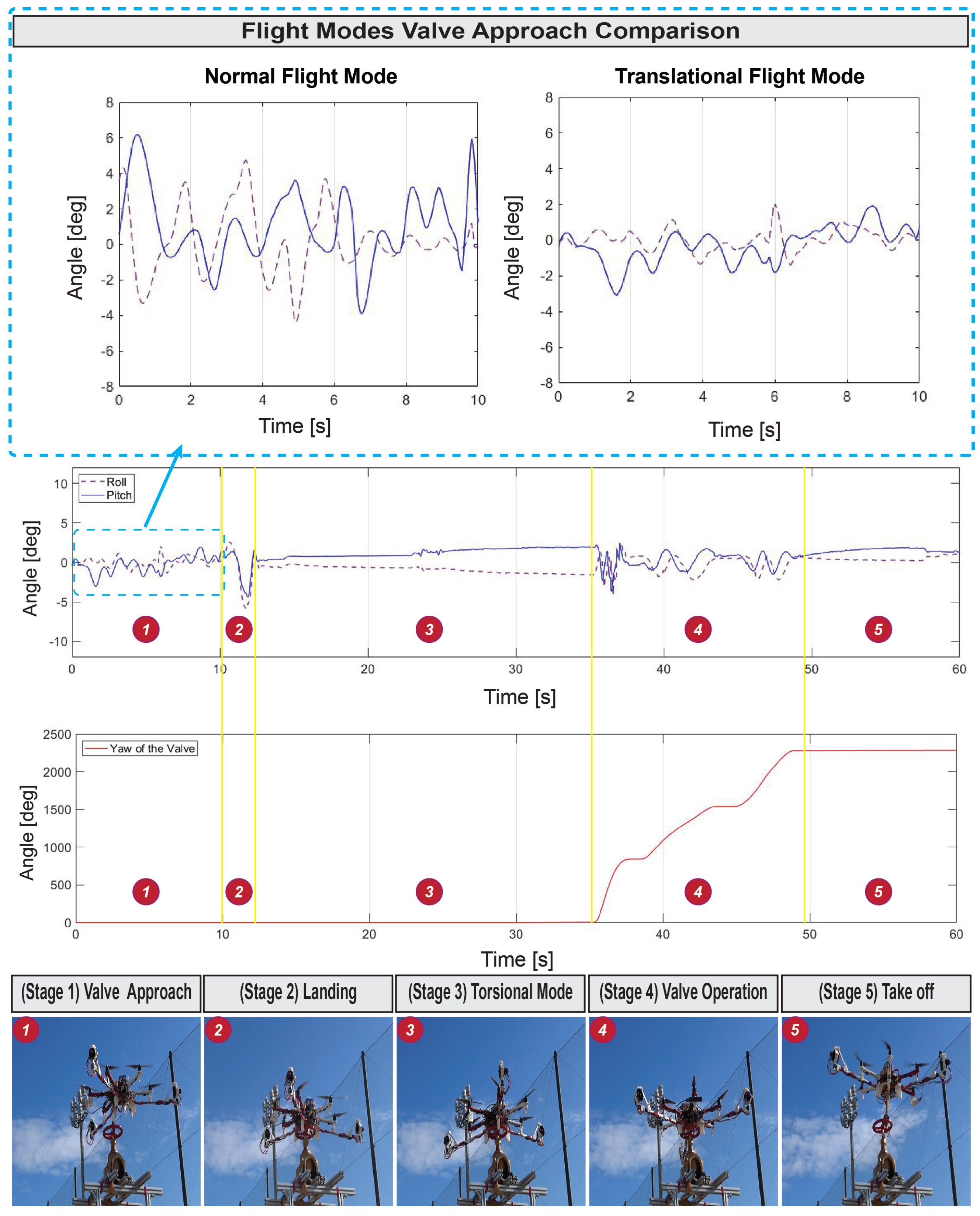
Translational flight mode: This configuration follows the control framework expressed in our previous research [16]. The EDFs are positioned as follows:
Θ T M = [ 120 ° ,   0 ° ,   240 ° ]
f x f y τ z = μ / 2 μ μ / 2 μ 3 / 2 0 μ 3 / 2 0 0 0 · ω 1 2 ω 2 2 ω 3 2
As shown in Figure 8a, this causes the thrust vectors T 1 ,   T 2 ,   T 3 to be collinear to the direction vector d 1 ,   d 2 ,   d 3 from the CoG to each respective frame. This produces a 0 net torque in τ Z . The only remaining components are the thrust forces, which allow for planar motion and forces. Based on the odometry information provided by the tracking camera module, the system is capable of holding its current position controlling the EDFs’ thrust vectors.
2.
Torsional work configuration: Assisted by the passive landing mechanism the system can land on the valve and transition to this mode. The propellers are disarmed, and EDFs are controlled to apply the required torque τ Z . The EDFs must be oriented so that the thrust vectors are perpendicular to their respective distance vector d i . Figure 8b correspond to the negative torque configuration with:
Θ C C W = [ 210 ° ,   90 ° ,   330 ° ]
f x f y τ z = μ 3 / 2 0 μ 3 / 2 μ / 2 μ μ / 2 d x 1 ( μ / 2 ) d y 1 ( μ 3 / 2 ) d x 2 μ d x 3 ( μ / 2 ) d y 3 ( μ 3 / 2 ) · ω 1 2 ω 2 2 ω 3 2
Figure 8c corresponds to the positive torque configuration with:
Θ C W = [ 30 ° ,   270 ° ,   150 ° ]
f x f y τ z = μ 3 / 2 0 μ 3 / 2 μ / 2 μ μ / 2 d x 1 ( μ / 2 ) + d y 1 ( μ 3 / 2 ) ) d x 2 ( μ ) d x 3 ( μ / 2 ) + d y 3 ( μ 3 / 2 ) · ω 1 2 ω 2 2 ω 3 2
This control allocation matrix can be solved with the Moore–Penrose pseudo-inverse for the angular velocities, which satisfy the desired forces f x , f y and torsional moment τ z .
Ω = A ^ · F M

6. Experimental Results

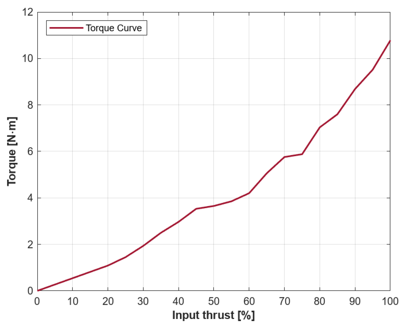
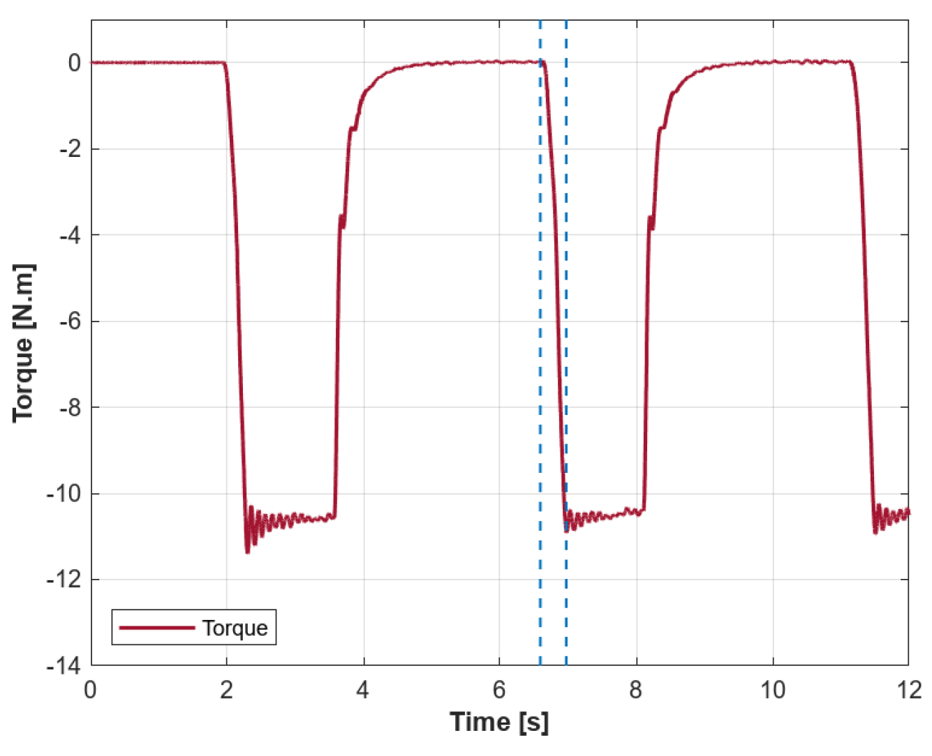
6.1. Torque Evaluation

For the initial torque measurement a industrial grade torque sensor was used to evaluate the torque capabilities of the system, where a relation between the percentage of thrust generated by the add-on system and the measured torque was obtained. The torque τ z can be observed in Figure 9, where its maximum torque magnitude is of 10.78 N · m. In contrast, the torque produced solely by UAV and its propellers, i.e., the induced torque, has a maximum torque magnitude of 0.6 N · m. Furthermore, Figure 10 shows a response time of 0.38 ms, which refers to the time the add-on thrust vectoring system takes to generate its maximum torque from its rest state.

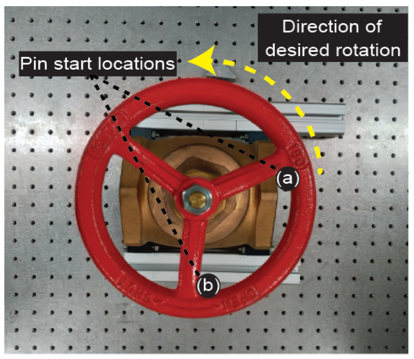
6.2. Pre-Flight Valve Rotation Evaluation

A pre-flight test was performed in order to evaluate the torsional capabilities of the system. The multirotor was placed on top of a valve simulating the post landing state. The experimental setup can be observed in Figure 11. The system was tested on a KITZ (A-100A) general purpose globe valve, with an external diameter of 180 mm and three internal spokes. This type of industrial valve through the manual operation of its round-shaped handle, is used for the regulation of water/steam applications. The torque necessary to operate a valve from a closed state is dependent on its dimensions and conditions, i.e., its maintenance history, lubrication, presence and degree of corrosion as well as other external factors. For this particular case, the valve required a torque of 3.7 N · m to be operated from its closed state.
Both rotation directions were evaluated, corresponding to opening and closing operations. For this experiment a distinction must be made regarding a direct rotation and that using the aid of an impact force. As described in Figure 12, the first case describes the situation where there is no impact force and the pin inside the mechanism is in direct contact with the valve’s spokes while initiating the rotation. The second case describes a situation where the system initially rotates along the valve, counter to the desired rotation taking the advantage of the gap’s distance between spokes. The valve acts as a guide providing a distance between the inner pin and the spokes, allowing for the generation of an impact force once the rotation begins. The initial rotation of the valve from its closed position, i.e., loosening of the valve, requires the highest amount of torque. Sustaining the rotation at an acceptable rate, requires lower torque than the initial magnitude. This permits the system to vary its output during the operation, controlling not only the torque magnitude but also as shown in Figure 11b, the desired rotation rate. In the direct rotation mode the system produces 3.71 N · m before a stable rotation of the valve is initiated. This corresponds to 35% of the available thrust. In contrast, when the rotation is assisted by above mentioned impact force, the torque required to open the valve from its shut state can be generated with 20% of the total available thrust.

6.3. Flying Task Experiment Mode Evaluation

For the field experiment, the same valve tested on the previous evaluations was used. A structure was constructed to place the valve for the operation experiment, in order to simulate a location a human operator would have difficulty reaching. The structure was built with aluminum pipes and had a total height of 1.5 m. Two operations modes were tested during this experiment, in order to evaluate the safe landing and operation of the valve. First, the normal flight mode where the drone has control of both its pitch and roll. Second, using the translational flight configuration, where the roll and pitch of the systems are kept close to 0°. This provides the operator with the option to select the mode most appropriate for the environment of the task. The manipulation task was divided in five stages as indicated in Figure 13, from the initial approach to the take off after the valve operation task is finished. In Stage 1 during the valve approach the normal and translational flight mode were evaluated. The results show the difference between the attitude values of each mode, where the translational flight mode’s pith and roll values are of lower magnitude. During the landing (Stage 2) the disturbances present in the attitude correspond to the pin coming in contact with top of one the spokes of the valve. However, the tapered cap functioned as designed by guiding the passive mechanism to its correct position. In Stage 3 the propellers were disarmed, and the system transitioned to its torsional mode. The sudden change of attitude of pitch and roll during the valve operation (Stage 4), are due to vibrations of the structure holding the valve and do not correspond to the UAV or the add-on device. Before the final stage the system transitioned to the translational flight mode and proceeded to the take off (Stage 5).

7. Discussion

The torque and pre-flight evaluations describe the torsional characteristics of the thrust vectoring platform and the robustness of the passive landing mechanism. The measurement reflects that the thrust vectoring device, can generate a torque magnitudes considerably higher than a conventional UAV multirotor. In addition by varying the exerted torque the system is capable of higher rotation rates during the manipulation task, reducing the total time of operation.
The passive landing mechanism is designed to provide a simple solution for interacting with industrial valves. In addition its tapered cap allows the positioning of the mechanism’s pin to be close to the spoke of the valve if this were to land on top of it, as demonstrated during the landing of Figure 13. However, there could be a situation where the top flat area of the tapered cap can become stuck with the spoke during the take off stage. A cap with a double cone shape, formed by joining two identical cones at their bases, could provide the same safety sliding function for landing stage, but also reduce the possibility of it becoming stuck on the spoke during take off.
Furthermore, the challenges addressed by the thrust vectoring device are not unique to valve manipulation. The solution presented in this paper could be further expanded to consider to other types of similar torsional work. Task such as bulb manipulation [3] and fruit harvesting [25], present similar characteristics regarding their location and orientation. However, is important note that these task would require special considerations regarding their gripper designs and grasping strategies.
The flight and manipulation experiment in Figure 13, demonstrates the thrust vectoring device operating in the hover state of the UAV for its translational motion. By operating the multirotor in its hover state, the separation of the control of the UAV and the add-on device is made possible. This greatly simplifies the control of the system and also proves to be enough to realize the translational motion and operate a horizontal valve. However, in situations where valves are of small dimensions or the rotation axis of the object of interest is placed at different orientations, e.g., vertical valves, landing is no longer feasible. This would require the system to realize the valve manipulation during flight. The current control model can be further improved to take full advantage of all the available actuators and address these scenarios. Future extensions of this research will include the integration of the propellers to the control solution. Taking advantages of the strengths of the propeller, which in contrast to their yaw can generate higher torques in relation to their roll and pitch rotation. This would expand the forces and torques available to the UAV, increasing the motion and manipulation capabilities of the system.

8. Conclusions

This paper presents the design and development of an add-on thrust vectoring device for torsional tasks, which can be equipped on a commercial multirotor. The current design expands on our previous work of an add-on translational device, enhancing its applications for torsional manipulation. The thrust vectoring capabilities of the system allow for the rapid change between two operation modes, a translational motion in the hover state and torsional work on a valve.
The decoupling of the propellers’ thrust and the torque generated by three EDFs in the proposed system, allowed for the generation of torques of higher magnitude compared to the torque in the yaw axis of a conventional UAV. Furthermore, since the propellers are not engaged during the torsional task, the only force present is the weight of the system and the thrust of the EDFs, which allows for the design of a landing guiding mechanism, thus reducing the complexity of the fastening task.
In experiments the system capabilities where measured and evaluated. The add-on thrust thrust vectoring device is capable of generating a maximum torque magnitude of 10.78 N · m. Field experiments show the system landing on a horizontal valve, with a required torque of 3.7 N · m, and operating it from its shut state. During the valve operation the add-on device allows for continuous rotation as well as higher rotation rates, which can be controlled according to the requirements of the task and the characteristics of the valve (Supplementary Materials).

Supplementary Materials

A video demonstration of the developed system can be downloaded at: https://www.mdpi.com/article/10.3390/drones7090551/s1, Video S1: AerialTorsional.mp4.

Author Contributions

Contributions of the authors are as follows: R.R.M. developed the prototype and formal analysis, performed experiments, analyzed the results, and wrote the manuscript. H.P. analyzed the design, performed experiments, and wrote the manuscript. K.S. provided design considerations, supervised, validated results, and wrote the manuscript. All authors have read and agreed to the published version of the manuscript.

Funding

This research received no external funding.

Data Availability Statement

Not applicable.

Conflicts of Interest

The authors declare no conflict of interest.

Abbreviations

The following abbreviations are used in this manuscript:
AUVAutonomous Underwater Vehicles
CoGCenter of Gravity
COPCollinearly Oriented Propellers
DOFDegree of Freedom
EDFElectric Ducted Fan
IMUInertial Measurement Unit
NCOPNon-Collinearly Oriented propellers
UAVUnmanned Aerial Vehicles
UVGUnmanned Ground Vehicles

References

  1. Ruggiero, F.; Lippiello, V.; Ollero, A. Aerial Manipulation: A Literature Review. IEEE Robot. Autom. Lett. 2018, 3, 1957–1964. [Google Scholar] [CrossRef]
  2. Suarez, A.; Vega, V.M.; Fernandez, M.; Heredia, G.; Ollero, A. Benchmarks for Aerial Manipulation. IEEE Robot. Autom. Lett. 2020, 5, 2650–2657. [Google Scholar] [CrossRef]
  3. Shimahara, S.; Leewiwatwong, S.; Ladig, R.; Shimonomura, K. Aerial torsional manipulation employing multi-rotor flying robot. In Proceedings of the 2016 IEEE/RSJ International Conference on Intelligent Robots and Systems (IROS), Daejeon, Korea, 9–14 October 2016; pp. 1595–1600. [Google Scholar] [CrossRef]
  4. Rastegarpanah, A.; Ner, R.; Stolkin, R.; Marturi, N. Nut Unfastening by Robotic Surface Exploration. Robotics 2021, 10, 107. [Google Scholar] [CrossRef]
  5. Zhao, Y.; Gao, F.; Hu, Y. Novel method for six-legged robots turning valves based on force sensing. Mech. Mach. Theory 2019, 133, 64–83. [Google Scholar] [CrossRef]
  6. Newman, W.; Chong, Z.H.; Du, C.; Hung, R.T.; Lee, K.H.; Ma, L.; Ng, T.W.; Swetenham, C.E.; Tjoeng, K.K.; Wang, W. Autonomous valve turning with an Atlas humanoid robot. In Proceedings of the 2014 IEEE-RAS International Conference on Humanoid Robots, Madrid, Spain, 8–20 November 2014; pp. 493–499. [Google Scholar] [CrossRef]
  7. Ajoudani, A.; Lee, J.; Rocchi, A.; Ferrati, M.; Hoffman, E.M.; Settimi, A.; Caldwell, D.G.; Bicchi, A.; Tsagarakis, N.G. A manipulation framework for compliant humanoid COMAN: Application to a valve turning task. In Proceedings of the 2014 IEEE-RAS International Conference on Humanoid Robots, Madrid, Spain, 8–20 November 2014; pp. 664–670. [Google Scholar] [CrossRef]
  8. Konno, A.; Hwang, Y.; Tamada, S.; Uchiyama, M. Working postures for humanoid robots to generate large manipulation force. In Proceedings of the 2005 IEEE/RSJ International Conference on Intelligent Robots and Systems, Edmonton, AB, Canada, 2–6 August 2005; pp. 2548–2553. [Google Scholar] [CrossRef]
  9. Yang, H.; Park, S.; Lee, J.; Ahn, J.; Son, D.; Lee, D. LASDRA: Large-Size Aerial Skeleton System with Distributed Rotor Actuation. In Proceedings of the 2018 IEEE International Conference on Robotics and Automation (ICRA), Brisbane, Australia, 21–25 May 2018; pp. 7017–7023. [Google Scholar] [CrossRef]
  10. Orsag, M.; Korpela, C.; Bogdan, S.; Oh, P. Dexterous Aerial Robots—Mobile Manipulation Using Unmanned Aerial Systems. IEEE Trans. Robot. 2017, 33, 1453–1466. [Google Scholar] [CrossRef]
  11. Ramon-Soria, P.; Arrue, B.C.; Ollero, A. Grasp planning and visual servoing for an outdoors aerial dual manipulator. Engineering 2020, 6, 77–88. [Google Scholar] [CrossRef]
  12. Nguyen, H.; Alexis, K. Forceful Aerial Manipulation Based on an Aerial Robotic Chain: Hybrid Modeling and Control. IEEE Robot. Autom. Lett. 2021, 6, 3711–3719. [Google Scholar] [CrossRef]
  13. Zhao, M.; Nagato, K.; Okada, K.; Inaba, M.; Nakao, M. Forceful Valve Manipulation With Arbitrary Direction by Articulated Aerial Robot Equipped With Thrust Vectoring Apparatus. IEEE Robot. Autom. Lett. 2022, 7, 4893–4900. [Google Scholar] [CrossRef]
  14. Carrera, A.; Palomeras, N.; Hurtós, N.; Kormushev, P.; Carreras, M. Learning multiple strategies to perform a valve turning with underwater currents using an I-AUV. In Proceedings of the OCEANS 2015, Genova, Italy, 18–21 May 2015; pp. 1–8. [Google Scholar] [CrossRef]
  15. Administration, U. Water Supply Systems and Evaluation Methods; Volume I: Water Supply System Concepts; Fema: Washington, DC, USA, 2008. [Google Scholar]
  16. Miyazaki, R.; Paul, H.; Shimonomura, K. Development of Add-On Planar Translational Driving System for Aerial Manipulation with Multirotor Platform. Appl. Sci. 2021, 11, 1462. [Google Scholar] [CrossRef]
  17. Council, I.C. 2018 IPC, International Plumbing Code; International Code Council: Nappanee, IN, USA, 2018. [Google Scholar]
  18. Council, I.C. 2021 IFGC, International Fuel Gas Code; International Code Council: Nappanee, IN, USA, 2021. [Google Scholar]
  19. Brescianini, D.; D’Andrea, R. Design, modeling and control of an omni-directional aerial vehicle. In Proceedings of the 2016 IEEE International Conference on Robotics and Automation (ICRA), Stockholm, Sweden, 16–21 May 2016; pp. 3261–3266. [Google Scholar] [CrossRef]
  20. Ollero, A.; Heredia, G.; Franchi, A.; Antonelli, G.; Kondak, K.; Sanfeliu, A.; Viguria, A.; Martinez-de Dios, J.R.; Pierri, F.; Cortes, J.; et al. The AEROARMS Project: Aerial Robots with Advanced Manipulation Capabilities for Inspection and Maintenance. IEEE Robot. Autom. Mag. 2018, 25, 12–23. [Google Scholar] [CrossRef]
  21. Bodie, K.; Brunner, M.; Pantic, M.; Walser, S.; Pfändler, P.; Angst, U.; Siegwart, R.; Nieto, J.I. An Omnidirectional Aerial Manipulation Platform for Contact-Based Inspection. arXiv 2019, arXiv:1905.03502. [Google Scholar]
  22. Kamel, M.; Verling, S.; Elkhatib, O.; Sprecher, C.; Wulkop, P.; Taylor, Z.; Siegwart, R.; Gilitschenski, I. Voliro: An Omnidirectional Hexacopter With Tiltable Rotors. arXiv 2018, arXiv:1801.04581. [Google Scholar]
  23. Miwa, M.; Uemura, S.; Imamura, A. Arbitrary Attitude Hovering Control of Quad Tilt Rotor Helicopter. J. Robot. Mechatronics 2016, 28, 328–333. [Google Scholar] [CrossRef]
  24. Hasegawa, N.; Suzuki, S.; Kawamura, T.; Shimizu, T.; Ueno, H.; Murakami, H. Independent Attitude and Position Control of Non-planer Multi-rotor Helicopter. J. Robot. Soc. Jpn. 2020, 38, 192–198. [Google Scholar] [CrossRef]
  25. Shankarpure, M.R.; Patil, D.D. A Comprehensive Survey on Methods and Techniques for Automated Fruit Plucking. Int. J. Intell. Syst. Appl. Eng. 2023, 11, 156–168. [Google Scholar]
Figure 1. Add-on thrust vectoring device for quick accurate positioning and valve operation.
Drones 07 00551 g001
Figure 2. UAV with add-on thrust vectoring system components. (a) Thrust vectoring device. (b) Realsense tracking camera. (c) Passive landing mechanism in its landed state.
Drones 07 00551 g002
Figure 3. Top-view of add-on thrust vectoring device without the UAV.
Drones 07 00551 g003
Figure 4. Block diagram of the proposed system.
Drones 07 00551 g004
Figure 5. (a) Side view of the passive landing mechanism. (b) Bottom view of passive landing mechanism and its pin with tapered cap in contact with valve’s spoke.
Drones 07 00551 g005
Figure 6. (a) Side view of landing mechanism, where D1 = 182 mm and D2 = 250 mm (b) Landing rate of success from center offset.
Drones 07 00551 g006
Figure 7. Add-on thrust vectoring device coordinate system.
Drones 07 00551 g007
Figure 8. Evaluated operation mode configurations.
Drones 07 00551 g008
Figure 9. Plot of torque response for different values of input thrust. Maximum Torque = 10.78 N · m.
Drones 07 00551 g009
Figure 10. Response time of 0.38 ms for the system to reach its maximum torque value.
Drones 07 00551 g010
Figure 11. (a) Experimental setup for a KITZ (A-100A) valve from its locked state, with a required torque of 3.7 N · m. (b) Yaw rate for feasible valve operation. Min. rate = 3.63 rad/s. Max. rate = 17.25 rad/s.
Drones 07 00551 g011
Figure 12. Start location of the pin: (a) direct rotation and (b) impact assisted rotation.
Drones 07 00551 g012
Figure 13. Sequence for a horizontal valve manipulation task: (1) Attitude comparison of valve approach for normal and translational flight modes. (2) Landing on horizontal valve. (3) Mode change to torsional mode. (4) Valve manipulation. (5) Take off.
Drones 07 00551 g013
Table 1. Specification of the add-on thrust vectoring device.
Gross weight1.01 kg without battery
Distance to EDF from center53 cm
Number of EDFs3
EDF characteristicsPowerfun EDF ϕ 50 mm/4300 KV
Max thrust9.31 (N) for each ducted fan
Servomotors characteristicsDynamixel XL330 (0.228 N · m)
EDFs range of motion±360°
Table 2. Notations used in this paper.
SymbolDescription
F = [ f x ,   f y ,   f z ] T Resultant forces acting on the center of gravity ( i = 1 , 2 , 3 )
M = [ τ x ,   τ y ,   τ z ] T Resultant moments acting on the center of gravity
T i Thrust force vector generated by the EDFs ( i = 1 , 2 , 3 )
d i = [ d x i ,   d y i ] Distance vector from the CoG to each EDFs’s frame ( i = 1 , 2 , 3 )
Θ = [ θ 1 ,   θ 2 ,   θ 3 ] Angular position of the EDFs
ω i Angular velocity of the EDFs
Ω = [ ω 1 2 ,   ω 2 2 ,   ω 3 2 ] T Vector of squared angular velocities
μ Lift force coefficient
kAerodynamic drag coefficient
C i , S i c o s ( θ i ) and s i n ( θ i )   ( i = 1 , 2 , 3 )
Disclaimer/Publisher’s Note: The statements, opinions and data contained in all publications are solely those of the individual author(s) and contributor(s) and not of MDPI and/or the editor(s). MDPI and/or the editor(s) disclaim responsibility for any injury to people or property resulting from any ideas, methods, instructions or products referred to in the content.

