Review

Tendon-Driven Continuum Robots for Aerial Manipulation—A Survey of Fabrication Methods

by
Anuraj Uthayasooriyan
1,*,
Fernando Vanegas
1,
Amir Jalali
2,
Krishna Manaswi Digumarti
1,
Farrokh Janabi-Sharifi
2 and
Felipe Gonzalez
1
1
QUT Centre for Robotics (QCR), School of Electrical Engineering and Robotics, Queensland University of Technology, 2 George Street, Brisbane 4000, Australia
2
Department of Mechanical and Industrial Engineering, Toronto Metropolitan University, 350 Victoria St, Toronto, ON M5B 2K3, Canada
*
Author to whom correspondence should be addressed.
Drones 2024, 8(6), 269; https://doi.org/10.3390/drones8060269
Submission received: 4 April 2024 / Revised: 9 June 2024 / Accepted: 12 June 2024 / Published: 17 June 2024
(This article belongs to the Special Issue Advances in Quadrotor Unmanned Aerial Vehicles)

Abstract

:
Aerial manipulators have seen a rapid uptake for multiple applications, including inspection tasks and aerial robot–human interaction in building and construction. Whilst single degree of freedom (DoF) and multiple DoF rigid link manipulators (RLMs) have been extensively discussed in the aerial manipulation literature, continuum manipulators (CMs), often referred to as continuum robots (CRs), have not received the same attention. This survey seeks to summarise the existing works on continuum manipulator-based aerial manipulation research and the most prevalent designs of continuous backbone tendon-driven continuum robots (TDCRs) and multi-link backbone TDCRs, thereby providing a structured set of guidelines for fabricating continuum robots for aerial manipulation. With a history spanning over three decades, dominated by medical applications, CRs are now increasingly being used in other domains like industrial machinery and system inspection, also gaining popularity in aerial manipulation. Fuelled by diverse applications and their associated challenges, researchers have proposed a plethora of design solutions, primarily falling within the realms of concentric tube (CT) designs or tendon-driven designs. Leveraging research works published in the past decade, we place emphasis on the preparation of backbones, support structures, tendons, stiffness control, test procedures, and error considerations. We also present our perspectives and recommendations addressing essential design and fabrication aspects of TDCRs in the context of aerial manipulation, and provide valuable guidance for future research and development endeavours in this dynamic field.

1. Introduction

In this paper, we begin by briefly outlining the current state of aerial manipulation with drones and the challenges they face. Following that, we offer a comprehensive summary of the existing research on continuum manipulator (CM)-based aerial manipulation systems. Additionally, we emphasize the advantages of utilizing CM-based aerial manipulation over RLM-based systems. Subsequently, we delve into the study of fabrication methods employed for continuum manipulators. While our survey is conducted with the aim of benefiting aerial manipulation systems, we also acknowledge that the insights from our prototyping survey can extend to other application domains.

1.1. Overview of Aerial Manipulation Systems

The willingness to employ UAVs is increasingly evident across various research sectors, industries, government sectors, and the general public. Applications have primarily centered on industrial inspection and monitoring [1], precision agriculture [2,3], disaster management [4], environment monitoring [5,6,7], smart city operations [8], military operations [9], space and planetary exploration [10,11], archaeological exploration [12], and more. The application domains are actively expanding as cutting-edge control and manufacturing technologies are continuously researched and applied in practical scenarios.
Various aerial platforms have been developed according to the demands of specific applications. While many of these developments focus on monitoring, inspection, and viewing-related applications, a significant portion also involves aerial manipulation [13,14]. UAVs intended for monitoring and inspection tasks are typically equipped with cameras and additional sensors. Many of these vehicles do not physically interact with the environment. This limitation has hindered the full utilization of UAVs in real-world scenarios. Addressing this bottleneck has led to the concept of aerial manipulation, where UAVs are empowered to perform tasks beyond monitoring and inspection. These tasks encompass perching, grasping, and manipulating activities, in addition to their monitoring and inspection capabilities.
Drones in the form of multirotors, such as helicopters, octorotors, hexarotors, quad-rotors, etc., are becoming a popular choice for aerial manipulation tasks [13,14]. These multirotor-based AMSs are developed with various RLM morphologies [14]. Some examples of AMS morphologies include multirotors attached with a gripper [15], a single DoF-RLM [16,17], two or multiple DoF-RLM [18,19,20], multiple arms [21,22], and a parallel manipulator [23,24]. Furthermore, there are attempts to develop a swing load method of manipulation designs [25,26]. Apart from the perspective of manipulator arm design, fully actuated multirotor UAV designs incorporating tiltable rotor morphologies [27] and tethered UAV [28,29] developments are also underway.
While each of these approaches has its contextual advantages, they also come with limitations. Helicopters can handle large payloads with a higher level of freedom, but are limited to working in open environments. Tethered UAVs are lightweight and can handle objects with a better power-to-weight ratio, but have restrictions in their workspace, freedom, and reach. Small UAVs equipped with grippers excel in grasping operations, particularly in structured and less cluttered environments. RLM-attached aerial robots surpass all the previous examples in terms of workspace and degree of freedom (DOF), however, due to the limitations that RLMs possess in terms of dexterity, reach, power-to-weight ratio, flexibility, compliance, and the safety of the environment and humans, UAVs equipped with RLMs are not effective, especially when the manipulation space is cluttered. Furthermore, employing RLM-enabled UAVs raises safety concerns, particularly in robotics situations where human interaction is required. Moreover, all the RLM-based UAVs design morphologies lack compliance with the environment. Overall, these aspects are crucial in understanding existing aerial manipulation, considering both their strengths and challenges [13,14,30,31].
When the need for a compliant and safe manipulation system arose, research works proposed control-based solutions [32,33,34], while another set of attempts focused on achieving compliance through mechanical design [35,36,37]. Although virtual impedance control-based solutions were proposed, the complexity and issues with sturdiness under different external conditions favored mechanical compliance-based designs. As a result, considering mechanical compliance, dexterity, and safety aspects, researchers began focusing on developing aerial robots as continuum arm aerial manipulation systems (CAAMSs).

1.2. Overview of Continuum Arm Aerial Manipulation System (CAAMS)

Continuum manipulators can present several task-specific advantages for aerial manipulation. These include the inspection of cluttered scenes in industrial environments, corner inspection of building infrastructures, examination of duct systems in industrial plants, and applications in agricultural operations. Despite the substantial growth in research and development concerning rigid link manipulators for aerial manipulation systems, continuum manipulator-enabled aerial manipulation systems are still in their infancy, with only a few research records emerging over the last few years. The objective of uncovering the potential of continuum manipulators (CMs) beyond medical applications can be effectively harnessed in the field of aerial manipulation. Aerial manipulation poses challenges in controlling two systems, primarily the unmanned aerial vehicle (UAV) and the manipulator. We firmly believe that providing a summary of the current state of research on continuum manipulator-based aerial manipulation systems, alongside a design and prototyping-oriented summary of CMs, can significantly benefit researchers and engineers focusing on integrating a continuum manipulator with a commonly available UAV platform.
The Figure 1 depicts a CAD model of a CAAMS with a TDCR. There have been notable endeavours to harness the potential of continuum manipulators for aerial manipulation tasks [31,38,39,40,41,42,43,44,45,46,47,48]. These works are discussed under the Section 2. When it comes to aerial manipulation, payload weight, dexterity, manoeuvrability of the manipulation system, compliance, and safety of the environment and humans are considered important factors [31]. In this respect, CMs possess advantages over RLMs [38,45]. In modern day, various UAV systems are being researched or used for several manipulation applications, such as non-destructive inspection of industrial sites [1], agriculture [49,50], application in construction industry, including inspection [17,51], water body sample collection [52], search and retrieve [53] operations, etc. These application domains in general exhibit non-uniform space with obstacles, hence high compliance and dexterity are required to perform the tasks with ease. Even though there are several RLM-based aerial manipulation systems proposed by various research studies, only a few applications have been implemented for real world use cases. This might be due to the limitations of RLMs in terms of the aforementioned traits required for aerial manipulation tasks. Therefore, tapping the potentials of CMs for aerial manipulation can pave the way for many effective real-world applications. Figure 2 depicts two different conceptual application possibilities of CAAMSs, where Figure 2a shows a CAAMS in a water sampling application and Figure 2b shows a cooperative aerial manipulation task.

1.3. Overview of CRs

Continuum robot (CR) research has been an active field of research for over three decades [54,55] and has seen exponential progress during the last decade (until the time of writing), as shown in Figure 3. The exploration of continuum manipulators began in the 1960s with the introduction of Orm, a pneumatically-actuated hyper-redundant manipulator developed by researchers at Stanford University [56]. Following the development of Orm, the first tendon-driven, hydraulically actuated, hyper-redundant manipulator, known as the ‘tensor arm’, was patented in 1968 [57]. Researchers further contributed to this field by introducing the first continuous backbone tendon-driven manipulator named ‘Elastor’.
Various definition statements exist for characterizing continuum robots. This paper adopts the definition provided by [58], synthesizing prior definitions by [59] and [60]. Accordingly, a continuum robot is described as follows: “A continuum robot is an actuatable structure whose constitutive material forms curves with continuous tangent vectors” [58]. This definition serves to clearly differentiate continuum manipulators from multi-link backbone robots. These multi-link backbone robots are referred as ‘quasi-continuum robots’ in some literature. Moreover, it is essential to specify that our survey exclusively addresses manipulator robots constrained on one end. The scope does not encompass snake robots or any other types of mobile continuum robots.
While articulated rigid link manipulator (RLM) robots, the counterparts of continuum robots (CRs), continue to dominate various application areas, CRs have garnered significant attention in the medical industry, particularly within surgical procedures. Extensive research and development efforts focused on surgical applications have robustly demonstrated the capabilities and advantages of continuum robots, while also highlighting the associated challenges [58,61,62]. It is noteworthy that the versatility of continuum manipulators (CMs) extends beyond the medical field. Research and implementations have showcased the suitability of CMs in diverse domains, including inspection and maintenance, fluid delivery applications, operations in hazardous environments, object manipulation, and cleaning [63,64,65,66].

1.4. Categories of CRs

According to the review work [64] on continuum robots (CRs), these robots can be categorized into two groups based on actuation methodology: (1) extrinsic actuation and (2) intrinsic actuation. In intrinsic actuation, the actuation occurs within the body of the CR itself, whereas extrinsic actuation involves actuators placed at the base of the continuum robot. Within extrinsic actuation, CRs can further be subcategorized as (1) TDCRs, (2) concentric tube robots (CTRs), and (3) rod-driven continuum robots (RDCRs). The intrinsic actuation class encompasses (1) fluid muscle robots (FMRs) and (2) soft growing robots (SGR). A more detailed exploration of these classes is available in [64]. It is worth noting that the development of SGRs and FMRs is still in its early stages, compared to CTRs and TDCRs. This indicates that these technologies may require a significant amount of time to reach maturity before they canbe utilized in practical applications like aerial manipulation. Therefore, extrinsically-actuated designs from the literature are examined, while focusing on aerial manipulation as the primary application.
Each type of continuum robot (CR) boasts a distinctive design (in this work, the term ‘design’ is used to refer the CR’s structural aspects only), along with its unique strengths, limitations, and capabilities. The CTRs stamped their strong utilization in the medical industry [61,67,68] and many high-tech medical industries adopted them for surgical equipment and system development. CTRs feature specially-treated and manufactured hollow tubular profiles, where a single tube or multiple concentrically arranged tubes function as the manipulator. The driving mechanisms for CTRs typically involve motor-driven lead screws or linear track and pinion mechanisms [68]. However, these mechanisms are complex, and the driving compartment that encapsulates them is bulky compared to those in tendon-driven continuum robots (TDCRs).
TDCRs are often conceptualized as flexible spines with multiple parallel-arranged supports, radially surrounded by flexible tendons. RDCRs are similar in design, but use flexible rods instead of tendons to actuate the continuum body. In most cases, the tendons of TDCRs and rods of RDCRs are actuated by electrical motors, serving as force transmitters from the driving motors [69]. Some innovative designs integrate the electro-mechanical and control aspects of both CTRs and TDCRs [68]. Figure 4 provides a classification of TDCRs under two major categories based on the backbone design: (1) continuous backbone TDCRs and (2) multi-link backbone TDCRs. The multi-link backbone TDCRs are also referred as ‘quasi-continuous tendon-driven robots’ in some literature. The classification further indicates the different most common material choices available for elastic backbones of TDCRs and the support structures. From these classifications, selected design details, excluding fluid pressure-supported backbone designs and other designs unsuitable for aerial manipulation, are discussed under the Section 4.
In the aerial manipulation stand point, a continuum manipulator should be slender, have a compact structure, suitable weight capacity for inspection related manipulation, and ease of scalability, while maintaining compactness [31]. There are many types of extrinsically-actuated continuum robots (CRs) based on the actuation methodology and structure they use, such as concentric tube, tendon-driven, fluid-based, and magnetic integrated actuation designs. However, fluid-based CRs are comparatively heavier and bulkier in size, and magnetic integrated designs are not suitable, as they can interfere with the UAV and the environment. Considering the aforementioned facts, we believe the tendon-driven design excluding the fluid pressure-supported designs can be more suitable for CAAMSs. In this context, there is a recent survey covering the design and fabrication methods of CTRs [68], which is useful in providing the design and fabrication details of CTRs. Therefore, our focus mainly concentrates on studying TDCRs for aerial manipulation systems.

1.5. Previous Literature Surveys on CRs

Numerous literature reviews in the domain of continuum robotics (CRs) comprehensively address various aspects, including overall design, modelling, control, path planning, navigation, applications, and future perspectives. Figure 5 illustrates the distribution of existing literature across the major aspects of CRs focusing on (a) overall review, (b) vine robots, (c) actuation, (d) applications, (e) medical, (f) design/modelling, (g) control/navigation, (h) fabrication, (i) grasp/grip, (j) performance evaluation, (k) sensing, and (l) stiffness tuning. It is evident that many reviews have focused on design, modelling, control, and navigation, while few have delved into actuation, sensing, stiffness tuning, grasping, and fabrication. Additionally, Figure 3 demonstrates a significant and rapidly increasing interest in CRs among researchers.
The discussion in the above paragraph implies the need for a comprehensive reference document containing all possible options related to fabrication of continuum robots (CRs). This document would prove invaluable for researchers or developers focusing on integrating CRs into new applications, such as aerial manipulation, mobile ground manipulation, inspection operations, and control strategy evaluations. Having a centralized reference can facilitate the creation of prototypes without unnecessary struggles and time wastage. The absence of a dedicated and structured set of reading materials that thoroughly explains the design and fabrication methodologies for CRs is currently a scarcity. Therefore, there is a crucial gap to be filled in terms of providing a complete and organized resource for those involved in CR research, development, and enthusiasts. Such a resource could allow researchers and developers to allocate their time more effectively, addressing challenges like control, planning, navigation, and the integration of CRs into new real-world applications.
At this juncture, we again recall that Nwafor et al. identified a gap in the design and fabrication methods within the concentric rube robots (CTR) class and made commendable efforts to address this demand [68]. Inspired by [68] and recognizing the efforts of the Open Continuum Laboratory, University of Toronto in supporting CR development globally, we have undertaken a literature survey on the fabrication of tendon-driven continuum robots (TDCRs), while discussing their suitability for aerial manipulation, including multi-link backbone TDCRs. This survey aims to fill another segment of the literature gap, focusing on TDCRs. In terms of ensuring the reproducibility of CRs as a system, we firmly believe that, in conjunction with [68], our work will provide a robust foundation.

1.6. Contribution of This Work

  • Providing a summary of existing works on CAAMSs and our perspectives on the research horizon;
  • Summarising the literature of prototyping materials and methodologies of continuous backbone TDCRs/multi-link backbone TDCRs/manipulators (hereafter, the term ‘flexible manipulators’ will be used to refer both the types together) under a well-structured classification. We study the aspects of flexible manipulators through the following categories: (1) multi-link backbone TDCRs, (2) preparation of TDCR backbone, (3) fabrication of TDCR support structure, (4) tendons, (5) stiffness tuning, and (6) errors and calibration in the TDCR synthesis. This classification provides a systematic approach to understanding various aspects of flexible manipulators and their fabrication;
  • Our perspectives on different aspects of flexible manipulator components and fabrication towards aerial manipulation using drones.

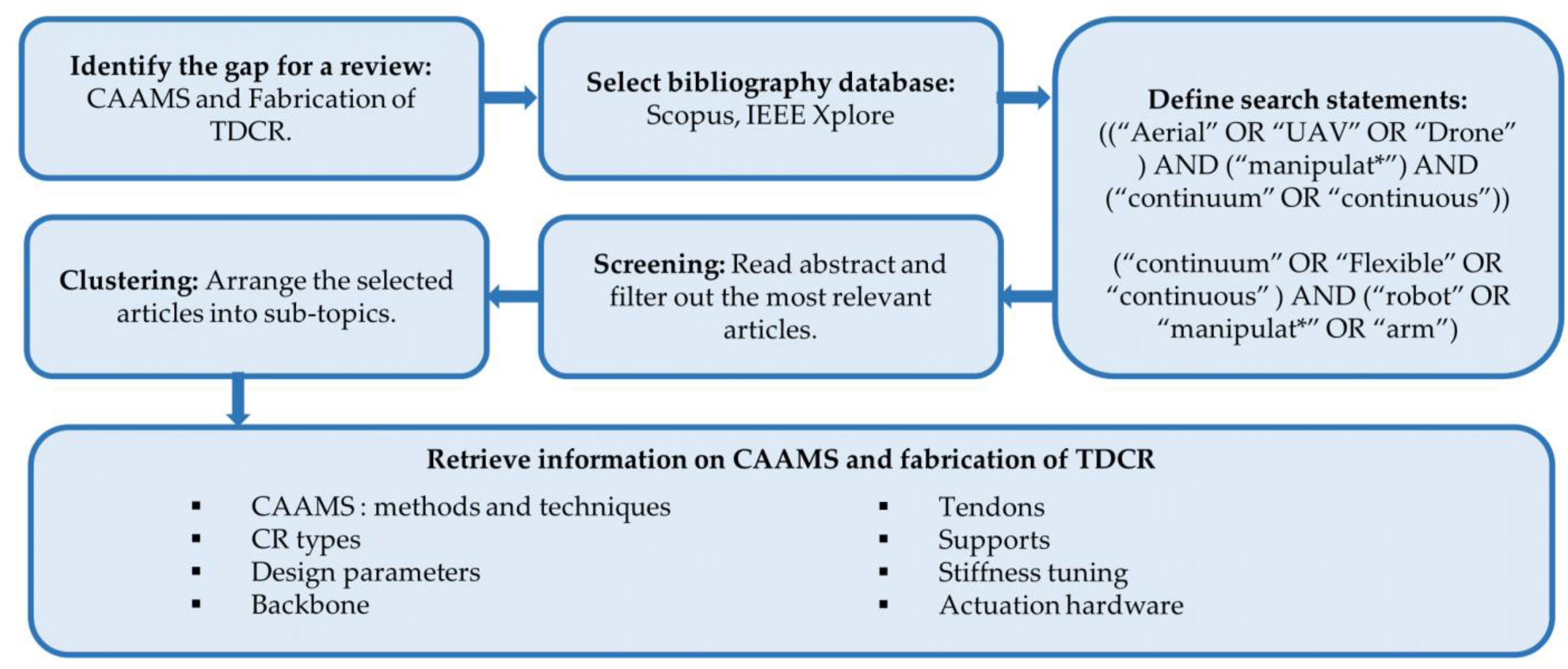
1.7. Review Methodology

A thorough study and summarisation of research publications available at the time of writing this paper have been conducted. The focus of the study is primarily on research publications from the last decade, along with key design and fabrication-oriented early research. Patent works have been excluded from this study. Additionally, publications that do not explicitly cover fabrication details have not been included. The information extraction method is graphically illustrated in Figure 6.
Emphasizing the original intention of this survey, which is to provide fabrication options for researchers and developers working on the integration of TDCRs for various applications, it is important to note that this work specifically investigates well-developed, common types of designs. New approaches that explore innovative and not fully developed methods for TDCRs, such as origami-based designs [113,114], braided designs [115], bio-mimicking approaches, etc., are not covered. Similarly, within the multi-link backbone TDCRs category, considering the compactness, design evolvement, wider adaptation, and less complexity, only the cross universal joint type and globe joint type robots are included. The article begins by providing an overview of current horizon of the CAAMS research in Section 2, followed by a concise overview of the design parameters in Section 3. Subsequently, Section 4 comprehensively addresses the fabrication and preparation of multi-link backbone TDCRs, TDCR backbones, TDCR support structures, tendons, actuation units, methods of stiffness control, and errors and calibration. In the conclusion, the key aspects of the study are summarised.

2. Continuum Arm Aerial Manipulation Systems (CAAMS)

Continuum manipulators (CMs) designed for aerial manipulation and integration with multirotor unmanned aerial vehicles (UAVs), hereafter referred to as CAAMSs, have been the subject of investigation by a limited number of studies. Jalali and Janabi-Sharifi, proposed a set of conceptual systems for aerial manipulation utilizing continuum manipulators [31]. They explored various configurations, including UAVs with a single CM, multiple CMs, collaborative CAAMSs, and UAVs with extensible CM. In this work, they also conducted benchmarking of aerial manipulators (AMs) while comparing CMs against rigid link manipulators (RLMs) and stated the advantages and challenges of using CMs.
Additionally, as indicated by [38,45,116], continuum arm robots exhibit specific advantages over RLMs. These research works further suggest that at present, there are only a few features, such as payload capacity, agility, controllability, path planning, and positioning, posing challenges to CMs compared to RLMs. Despite these challenges, CMs demonstrate superiority over their counterparts in many other aspects, including safety, dexterity, handling unstructured environments, and flexibility. The challenges with CMs mentioned here are applicable when it comes to CAAMSs, since the aerial vehicles incorporate CMs for aerial manipulation. Therefore, an area that offers opportunities for further research is the control and navigation of CAAMSs toward producing a robust system that can perform useful aerial manipulation tasks precisely and accurately.
Researchers undertook the modelling of a CAAMS with a single continuum manipulator (CM) and simulated its dynamics and control [45]. In this attempt, the aerial manipulation system was considered, such that the CM and the UAV are treated as two separate systems for modelling their dynamics, employing the Cosserat rod and Cosserat string models to model the continuum arm. To ensure a set of real values for the CM’s structural parameters, the researchers utilized the design parameters given in one of the previous CM works [117]. Conversely, in another work, considering the UAV and the CM together as a single system, modelling and control simulation were performed using the Euler–Lagrange theorem [16]. A CAAMS featuring two continuum robotic arms has been proposed, encompassing modelling, pre-grasp planning, and control [42], aimed at enhancing load handling capacity, stiffness, and compliance. This research used Euler–Lagrange method for modelling and experimented the developed control and planning strategies through simulation. Ghorbani and Janabi-Sharifi developed a method for state estimation CAAMSs using deep neural networks (DNN) and extended Kalman filter (EKF) for dual-arm CAAMSs [43].
Only a few attempts have been made to construct prototypes of CAAMSs. A NiTi backbone CM was prototyped with a 3D printed support structure and tested for use with UAVs [118]. This continuum robotic arm is tendon-driven and was experimentally assessed for its kinematics on a UR5 robotic manipulator simulating the UAV-base. Alongside the kinematic behaviour, the arm underwent testing for its static properties. Given that the stiffness of CM is a critical parameter influencing payload capacity, researchers conducted stiffness evaluation for the arm prototype [118]. The study also recommended hardware specifications, including off-the-shelf actuators for CM fabrication, serving as a valuable starting point for those aiming to integrate CMs with UAVs. However, it is important to note that this prototype was not tested in an actual flight scenario.
A research project conducted at the Singapore University of Technology and Design developed a tethered continuum arm aerial manipulation system (CAAMS) where the CM arm segment is integrated with the UAV, and the actuation system is tethered from the ground [40]. In this setup, the CM features a NiTi backbone with 3D printed supports. However, the actuation is facilitated by a ground-based tethered tendon-driven system, wherein an actuator pack is mounted on the ground, and tendons are routed up to the UAV for CM control. Consequently, this system has limitations in operating at greater heights and in complex environments.
Researchers in University of Hongkong developed an aerial platform named AeCoM featuring a lightweight continuum manipulator (CM) that claims to exhibit precise end effector pose under external force [39]. It is important to note that the manipulator is a multi-link backbone TDCRs. It is constructed using 3D printed cross-universal joints with four spring-paths radially supporting the vertebrae. This work addresses the tendon slacking issue, an undesirable behavior in a continuum robotic arm under inertia forces during sudden acceleration. The primary objective of this continuum arm aerial manipulation system (CAAMS) is object grasping. However, it possesses a larger size compared to the UAV body, which may not be a desired feature in terms of power consumption and access to confined spaces. Table 1 offers an overview of the works conducted on CAAMSs to date, while indicating their main contribution.

2.1. Perspectives on CAAMS Research

The design of CAAMSs possibly needs to explore variations in terms of operating scenarios, including performing operations above the UAV’s body, operations below the body, and operations sideways. In each of these scenarios, the CM may need to be attached either on top, underneath or on an extended profile towards a side. These choices can pose challenges inherent to the design of CMs. For example, when attaching the CM, we need to take extra care to make sure CM will never interfere with the propellers. In addition, the CM’s mass should be distributed such that the system’s centre of gravity is kept with in a safe region for balancing. When the CM is taken to a side, the CAAMS design should counter-balance the mass of the CM. Furthermore, these design choices can directly impose challenges in dynamics modelling and control of the CAAMS, mainly due to the fluctuation of inertia and reactive wrenches due to the CM’s motion [16]. At this juncture, design variables could be investigated within the UAV design as well. For example, (1) variable angle tilt rotor UAVs for orienting the base of the CM in different poses, and (2) fixed angle tilt rotor UAVs to have fast response for changing orientations of the base, compared to variable angle tilt rotor UAVs [38], could be considered to exploit their capabilities for CAAMSs.
Additionally, means of providing translational motion capability to the CM with respect to the UAV body is also a critical factor in design. When the CAAMS is used for an inspection or maintenance task where a narrow passage or cluttered scene is present, translational motion freedom, in addition to the bending, is necessary. This necessity arises to navigate the CM through the desired path. Even though a UAV can provide translational motion, the accuracy and precision may not be enough to match the demand of the use case. Essentially, the modelling, control, navigation, and path following capabilities of a CM attached to a floating body (UAV) is highly challenging. The modelling and control problem can be even more challenging when the CAAMS needs to have coupled dynamics operation with a multi-CM installed, which is a highly non-linear problem [42], or when tasked to perform collaborative operation between multiple CAAMSs [31]. There are various control methods of CAAMSs attempted in simulation, including vision-based control [48] for coupled dynamics system with uncertainties, hybrid feedback control [47], and PID-SMC [42]. Employing methods involving machine learning and artificial intelligence techniques may benefit to bypass complex modelling and solve challenges [42]. However, consideration should be given to how feasible a control strategy is to implement a CAAMS for real-time operation.
Another prominent area to consider when developing a CAAMS is the method of state estimation and shape sensing for the CMs and CAAMSs [43,80,107]. The CMs need special focus, as they are intended to be utilized to deal with unstructured, cluttered, or difficult to access spaces. When CMs are designed, feasible state estimation hardware with fabrication feasibility and relevant state estimation methodology and algorithms also need to be focused on. This opens a completely unique research area in the CAAMS domain.
When aerial manipulation involves grasping-based operations, for example, pick and place tasks, the CM should be capable of catering the requirement. It can be achieved by either a dedicated gripper as the end effector, or by manipulating the continuum portion of the CM around the object. A detailed study on the various possibilities of grasping can be found from [105]. Further, when choosing gripping mechanisms, one should take care of the weight and size of the gripper, as it can greatly induce the inertia fluctuation when the CAAMS is in operation. Moreover, the actuation mechanism of the gripper can also influence the total weight of the CAAMS, which is crucial. Existing literature surveys on grippers can help to evaluate a gripper design, such as in [104,119,120] where they cover the options for soft grippers as well. Soft grippers would be beneficial when the aerial manipulation is performed in a force-sensitive environment. In addition to the grasping, the ability to compactly keep the CM around the middle of the UAV is important to avoid the tendon-slacking effects on the fly [39] and avoid unnecessary interaction with the environment.
From Table 1, it is evident that research activities, both in terms of quantity and the depth of exploration in the CAAMS domain, are still in their infancy. Most researchers limited themselves within simulation studies. Therefore, the potentials of CM for aerial manipulation warrant investigation on physical CAAMS, particularly with a focus on applications. This exploration should delve into various aspects, including design, manufacturing, control, navigation, guidance, safety, accessibility, payload capacity, reach, and dexterity. Hence, to support these types of research works focusing on real-world implications, there needs to be physical prototypes of CAAMSs. It also implies that to come up with a physical CAAMS, the availability of concise reading material encompassing the fabrication methods of CMs could ease the burden on the researchers.

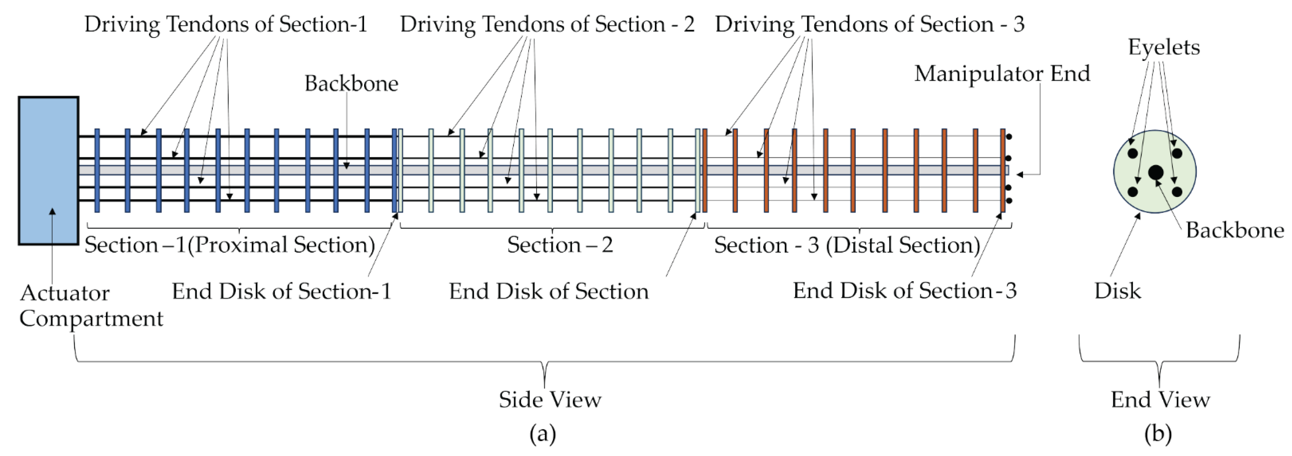
3. Elements of a TDCR

General Design of Typical TDCRs

Figure 7 presents the anatomy of a typical tendon-driven three-section robot. Here, it is assumed as there are two antagonistic pairs of tendons used for driving each section. Concerning design, morphologies can be explored from different angles. Examining the CR-backbone reveals various design classes, as shown in the Figure 4. Additionally, in terms of workspace and dexterity, the design of CMs is analyzed based on the number of sections they possess. In the case of a straight-path tendon-driven robot (different tendon routing are discussed under section xx), increased sections result in more versatile curves. Nevertheless, researchers have demonstrated that achieving versatile curves or shapes is possible within a single section of a CM, using helical tendon routing (HTR) [121,122,123].
In a TDCR, the backbone provides the shape while taking the load together with tendons. Tendons are also responsible for driving the continuum structure. The supports/disks provide the peripheral shape while facilitating guide holes (referred to as eyelets) for tendons. An early research work investigated the fundamental design parameters of an antagonistic tendon-driven CM using segment length (L), diameter of the supports (D), and eyelet height (H), as outlined within Figure 8. The path and length of the backbone centreline is considered for modelling the CM. The backbone is treated as thin, highly elastic, and non-extensible, and researchers have experimentally found a set of optimum design parameters for TDCRs with an elastic backbone under constant curvature assumptions [124].
The researchers of [124] defined a non-dimensional eyelet height (h) as the ratio between the eyelet’s normal distance from the backbone and backbone segment length at its natural position. They proposed a range of h, such that 0.2 < h < 0.5, with the optimal value being h = 0.4. This minimizes the error for using constant curvature kinematics against non-linear models. The researchers also determined the segment (space between two supports) design that minimizes tendon slack (S) (Smax = 2 − sum of the lengths of the cable pair of the segment under a particular driving condition). Hence, they found that h = 0.3 provides the critical value for Smax, thus the researchers proposed the increase of h to reduce the tendon slack. Reducing tendon slack is crucial to avoid tendon entanglement and prevent missing pulleys or guides and eliminate actuator backlash. As demonstrated, a large h is required to reduce the tendon slack, and this can be interpreted as reducing the segment length (gap between supports) to reduce the slack.
Even though many works have not reported on the total weight, including the actuation compartment to power ratio of the CMs, this ratio is one of the critical parameters when CMs are utilized for mobile manipulation applications or space applications. Those intending to use a CM for such applications should investigate any design in the literature for its weight-to-power ratio and ensure it has the required value for the intended application.
The equations given in the Table 2 can be useful in designing the CM’s geometry according to the application in hand. Non-dimensional load capacity can be used as a tool to make decisions during the design phase, as it can provide a measure of the robot’s ability to handle loads compared to its length, applied unit load, backbone diameter, and the selected material [124]. Non-dimensional eyelet height enables the designer to justify the CM design, such that it is optimized for the least tendon slack and accurate constant curvature kinematic implementation [124]. The slenderness ratio is an important factor to ease the ability of the CM to traverse through constrained space [125]. When variable length backbone, disk-supported CMs are designed, it is crucial to determine the maximum number of supports possible, along with the possible maximum curvature and minimum length to allocate, because all these three parameters are interrelated [126].
Avoiding singularity is crucial in CR operation. Generally, these robots can suffer from performance issues, such as an inability to move in certain directions, and lack the required accuracy and stiffness [127,128,129]. Singularity issues in continuum robots are investigated across various types, including TDCRs [130,131], CTR [132] and parallel continuum robots [127,133]. Since singularity is more of a design and modeling-oriented problem, and the primary focus is on the fabrication aspects of TDCRs, this paper does not cover a detailed discussion on continuum robot singularities.

4. Fabrication of TDCR

4.1. Preparation of Multi-Link Backbone TDCR Structure

Multi-link backbone TDCRs typically feature a snake-like spine (serpentine). They can be categorized broadly into cross-universal joints, globe/ball joints, and other types of joints. Cross-universal joints possess too rotational a DoF and globe joints have three rotational DoFs. Example CAD models of a globe joint and cross-universal joints are illustrated in the Figure 9.

4.1.1. Cross-Universal Joint

A cross-universal joint is composed of two orthogonal individual axes (Yaw and Pitch), facilitating two degrees of freedom (DOFs) of movement between two successive links in two perpendicular directions, thus the potential to create a 3D workspace. The discrete links with alternating diagonally-aligned joints contribute to the overall arm having high torsional stiffness. Additionally, this design allows for a significant degree of bending at individual links, while maintaining a high load-handling capacity [39,134,135,136,137,138,139]. Therefore, these types of manipulators are explored for applications beyond the medical field in the realm of continuum manipulators, including aeroengine repair [135], nuclear plant maintenance [136], and aerial manipulators for pick and place operations [39].
There are two main approaches followed in positioning the joints. Some designs choose to place the joints along the centreline of the backbone, resembling vertebrae [39,116], while others prefer to position them at the periphery or outer surface of a tubular-profiled manipulator design [134,136]. In the latter approach, the tendon guides (eyelets) are fashioned either in the form of welded guide rings radially attached to the joint supports [134,136], or as guide holes (eyelets) created on disks inserted at equal intervals throughout the manipulator. Conversely, the centreline-based joints method features radially extended flange/disk profiles around each joint, providing eyelets for routing the tendons [39,116,137].

Vertebrae Profile

In designs with vertebrae profiles, the structure is bolstered by radially arranged equidistant compression springs connected to the disk profiles. This configuration enhances the bending stiffness of the arm. Moreover, the tendons also pass through these springs. This design is comparatively less complex than the tubular-profiled one and can be fabricated using various methods such as 3D-printing of polymers or machining of materials like steel and aluminium [39,116,137,138,140,141]. When excessive force is applied through the actuating tendons, it may lead to excessive compression on the springs, causing undesired effects, such as buckling, in another plane. To address this issue, [137] a sliding link universal joint design capable of distributing excessive compression on a certain link-spring to other links can be incorporated.

Tubular Profile

The tubular-profiled structure offers space not only to accommodate tendons, but also flexible tools, wires, and any other necessary components that need to be taken up to the end of the manipulator without interfering with the outer environment [116,135,136,142]. These include signal/power cords for sensors, light sources, and end effector–actuators. In some designs, such tools or cords are directed through dedicated disks with lumens (holes) embedded across the length of the manipulator [142,143]. Material options for constructing the tubular-profiled cross-universal joint manipulator arm structure include the SUS 316 austenitic stainless steel containing molybdenum, titanium alloy, and 316L SS surgical stainless steel, etc.
Various manufacturing techniques are employed across different research works. Processing tough metals like titanium involves methods such as laser cutting [134] and CNC machining [134]. In the case of tubular designs, the links are manufactured and connected using a rivet pin [134], pin-free pivot-like contacts with compliant twin pivots [135], or pin-free rolling contact joints where all the links are connected through tendons [136]. There are a few works that have attempted 3D printing of the joint and the structure using polymers as well [144]. An innovative technique by Liu et al. produced a thin, one-bending DOF manipulator structure, without the need for assembly. The technique involved laser profile machining on a 2.2 mm diameter, 316L SS tube [142].
If the application requires traversing a narrow and long passage to reach the point of interest for performing the desired task, the manipulator could be designed with two stages: one feeding portion as the proximal part and a manipulation portion as the distal stage. In such designs, the feeding part’s stiffness and shape could be supported with a backbone made of materials such as NiTi rods [135,136]. When continuum manipulators are actuated extrinsically, the torque requirement increases with the mass of the manipulator. The cross-universal joint type manipulators made of metal are quite solid, as the joints occupy a significant volume of mass. Therefore, designs should consider mass optimization of CM’s components against the required strength, to enhance performance. The works [134,135,136] applied slots and bevel cuts on each individual link (or disks), which optimized the mass of the manipulator while the bevel cuts provided restricted bending.
Ma et al. presented an extensible manipulator comprising two sections arranged concentrically. They introduced a technique using steel wire mesh to cover the surface of the manipulator sections, enhancing torsional stiffness, and ensuring smooth translation of extensible sections. Additionally, this design incorporated a spring backbone within the internal section [134]. Guoxin Li et al. also employed wire mesh to cover the manipulator, facilitating navigation through narrow passages [136].

4.1.2. Globe Joint

The globe joint is designed in such a way that a spherical object (globe) freely turns inside a truncated, hollow sphere (globe seat). Each of these spherical portions is connected to different links. This morphology provides the joint with the ability to orient the connected bodies in any orientation with respect to each other, until they restrict the movement either by themselves or by an external body. In general, the joint is designed to accommodate a tendon guide structure with eyelets, and they are supported with springs between every two joints radially. Similar to vertebrae-type cross-universal joint robots, springs are typically mounted in a way that the tendons are routed through them [145,146,147]. A globe joint-based manipulator could be less stable and exhibits low stiffness. Incorporating helical springs [145,146,147] or flexure hinge [148] can increase the bending stiffness and stability of the manipulator. A CAD model shown in Figure 9a provides a general structure of globe joint. As spherical joints are comparatively difficult to produce, recent designs exploit 3D-printing techniques, which provide accuracy and weight reduction [145,147].
Researchers have introduced non-conventional designs using globe joints. Shen et al. created a three-section prototype with spherical joints applied with a sandpaper layer. This method provides variable stiffness through friction. In contrast to the conventional method of attaching radially aligned spring supports, this design introduced a series of springs placed along the center line of the robot [145]. Researchers synthesized a pipe-fish-inspired square cross-sectioned structure with globe joints made of glass ball and 3D-printing [147]. This design was proposed for whole-arm grasping of various objects.

4.1.3. Perspectives on Multi-Link Backbone TDCR Designs

Certain aerial manipulation applications, such as heavy object grasping, agricultural harvesting operations, and power tool handling in maintenance tasks, demand high strength, load-handling capacity, and torsional stiffness. Cross-universal joints can offer more torsional rigidity without compromising bending capability. However, the complexity in design and the increased number of individual components add more mass to the manipulator, making it less suitable for applications requiring a lightweight design. It can become heavier compared to an elastic backbone design, necessitating weight optimization methodologies. Nonetheless, innovative designs using carbon fiber as a manufacturing material or special topology-optimized 3D printing of the joints can overcome this limitation. Titanium alloy is preferable when a lightweight manipulator with high strength is expected. Moreover, SUS 316 and 316L stainless steel are corrosion-resistant, making them suitable for operating in environments susceptible to corrosion. 3D printing techniques can be a labor-efficient way to manufacture the arm, while optimizing weight. However, the friction between the links may be higher compared to molding or machining processes. Therefore, special operations such as sanding and applying a Teflon coating might be needed to reduce friction.
As discussed in Section 2.1, having a continuum manipulator (CM) with translational motion capacity is crucial for tasks where the aerial manipulator may need to navigate through complex environments. These include inspection of industrial infrastructure, precision agriculture, and environment sampling. Accommodating concentrically arranged multiple sections is a convenient design method to produce an extensible continuum manipulator with cross-universal joints. Such an extensible CM can exhibit the bending and translational motion required to navigate through complex environments. Laser profiling is suitable for accurately producing the designed components, especially for miniature designs. Miniature CM designs can be beneficial for miniaturized UAVs used for operations like pollination in precision agriculture. When the CM of an aerial vehicle is operated with grippers or power tools or sensing mechanisms, it is important to have a channel to keep the power and signal cables running from the tip of the CM to its base. Having the joints at the surface provides the advantage of lumens along the center line of the CM for these signal or power cables.

4.2. Preparation of TDCR Backbone

CM Backbones are prepared in various forms using various materials, such as elastic backbones made of springs [149], super-elastic solid metal rods [150], super elastic metal tubes [151], carbon fibre-based tubes [152], and soft materials like silicone [153].

4.2.1. Spring Backbone

Spring backbone robots are mainly fabricated using two types of helical springs, compression springs [123,154,155] and extension springs [156]. In most designs, the spring serves as an alternative to an elastic backbone medium. Other aspects, such as support structures, tendons, driving methods, etc., are the same as those discussed for elastic backbone robots in the following subsections. In many designs, the chosen spring is meant to provide flexibility for spatial bending, while some designs, the selected springs can allow for extension and contraction [155,157,158]. When springs are used as the backbone, they need to be covered with a flexible sheath to avoid tangling with the environment [154].
If the CM boasts a multi-section design, the sections are separated by spacer disks/solid couplings [149,155]. Springs have been opted for when the application requires a lengthier robot that can be compactly packed [125,149]. When translational motion is in place in other words, axial compression or extension is required, and all the tendons of a particular section are pulled or released synchronously by the same amount, so that a compression or extension of the spring backbone is achieved [154,155,156].
The spring backbone could be prepared either by having a single helical spring on which the supports are fixed [123], or multiple small length springs connected together by support disks [140]. Disk type supports are commonly used in conjunction with the spring backbone. When putting together a helical spring as a backbone, a challenge is to maintain a stable connection between the support disks and the spring. A possible solution could be making a spring with two different pitch variations. The spring could be designed to have subsequent coils with less pitch value, where the support disks could be easily connected to the spring. The rest of the portions of the spring will have a comparatively larger pitch [123]. A method of attaching the disks and the spring could be friction fit, gluing, crimping etc., based on the design limitations one would have. However, a friction fit or gluing may fail to keep the support disk at its primary position and orientation when the spring undergoes heavy deflections. The spring should not be under tension or compression or bending and should be straight when assembling with the disks. This will make sure the support disks are firmly fixed and aligned parallel among them, while perpendicular to the backbone. Proper crimping could be more stable compared to friction fit or gluing in this scenario.
When multiple springs are connected in series, the support disks can act as the connection interface between two subsequent springs [125,146]. When connecting multiple springs in series to produce a single backbone, the support disks can be made with longitudinally extended profiles with threads. These threaded profiles can be used to join the springs with the support disks, thereby producing a spring backbone made of multiple spring segments [140].
Remirez and Webster III demonstrated that multiple shapes within a one-section CM can be obtained by using a flexible spring and crossover elastic strips while utilizing a single actuator [154]. Researchers in the work [123] showed that multiple S-bending shapes can be created using a variable pitch spring and helical tendon routing. In their work, the spring was designed such that the positions where the support disks are to be fixed have a smaller pitch, ensuring a sufficient contact area for the disks. The remaining portion of the spring has a comparatively larger pitch. Another important point to note here is that the chosen spring should exhibit high enough rotational stiffness to avoid twisting, while providing sufficient bending flexibility.

4.2.2. Elastic Backbone

An elastic backbone in the context of a continuum robot could be understood as a thin rod, tube, wire, or sheet that does not undergo plastic deformation under loading conditions in the transverse direction. Further, it has the ability to return to its original shape once the load is removed. Elastic backbones are used for constant-length CMs and variable-length CMs in which the manipulator is extensible from a minimum size. When they are incorporated for extensible backbone fabrication, the structure is referred to as a telescopic backbone design or concentric tube backbones [151]. Basically, it is the adoption of the CTR’s manipulator design as the backbone for TDCRs. A concise review of concentric tube designs and fabrications can be found in [68]. Furthermore, the elastic backbone structure can be a single backbone as the central line of the TDCR, or multi backbones that are parallelly arranged along the length of the TDCR [150,159].
Commonly, there are four different choices for elastic backbone materials made among the research community; metal alloys, polymers, fibre-based materials, and silicone. The backbone material selection is mainly based on the application, task, and objective. When it comes to the cross-section’s anatomy of the backbone, most works opted for the circular cross-section, either in a solid form or hollow section, and some examples include [122,125,150,151,156,158,159]. This could be related to the capability to provide a uniform spatial bending in any direction and commercial availability of the material. However, there are few works that preferred rectangular [124] or triangular [160] cross-sectioned back bones, which are either commercially available or custom produced through 3D printing. If a design goal prefers more resistance against torsion, rectangular cross-sections could be a good choice, as they carry a large second moment of area for the same area of a circular cross-section.

Metal Alloy Backbone: Fixed Length

Spring steel [122,124,161] and nitinol (an alloy made of nickel and titanium—NiTi) are popular choices for metal alloy-based backbones. However, recent research works show a preference for super elastic nitinol backbones over spring steel, with available options including nitinol tubes, nitinol wires, and nitinol rods, for example [121,159,162,163,164,165]. From a fabrication standpoint, the challenge lies in accurately securing the supports to the backbone, unless the design is of a specialized nature that does not necessitate a singular fixed connection point between the support disk and the backbone. Various techniques are followed, such as crimping metal rings on both sides of a support [166], as illustrated in Figure 10 and applying adhesives [122,161]. A critical consideration during backbone preparation is the potential for changes in Young’s modulus due to applied modifications, attachments, and attachment methods [122]. All of these factors can affect the accuracy of the prototype compared to the respective mathematical model.

Metal Alloy Backbone: Variable Length

The importance of variable length CRs arises when it needs to be navigated through a torturous path. NiTi tubes in their austenite phase are utilized for making extensible TDCRs [126,151,167,168] Extensible TDCRs can have varying lengths, allowing the robotic continuum manipulator to possess variable arc lengths with varying radii of bending [169]. Researchers proposed various uses for extensible CMs, such as deployment in complicated paths, environments that are difficult to access, and implementing the follow-the-leader method for CM navigation. Primary design constraints for an extensible robot can be considered, including the following listed conditions [126,151]:
  • Expandability of the CM;
  • Controllability of the individual sections for their lengths if it is a multi-section CM;
  • Limit of the diameter of the CM;
  • Means of control on bending (extrinsic tendon actuation/intrinsic actuation);
  • Adjustability of section stiffness.
A continuum manipulator can be designed to be extensible in different ways, such as by using super elastic NiTi concentric tubes as backbones [151], incorporating Type-3 disks with magnetic repulsion that distributes the disks along the backbone [151,162] (please refer to the section C along with Figure 11 for disk types), and spring-loaded CT backbone with Type-1 disks [125] etc. [151] and [126] kept the proximal section with fixed length that also has Type-0 disks that are rigidly fixed to the backbone. In addition to these, a hybrid approach is also possible where a solid elastic backbone TDCR with disks and a disk-supported tube are assembled in a way that the former moves inside the latter. [167]. The concentric tube backbone can be actuated for varying the length using a rack and pinion-driven linear stage [126] or a screw carriage mechanism [126,162] etc. In such designs, each extensible individual section requires a dedicated actuation mechanism for varying its length.
However, there is another design approach that does not require dedicated actuators for length variation. Researchers have shown that employing spring supports along the length of the concentric tube backbone can provide longitudinal compliance [125,156]. In [125], the researchers proposed a robot identified as a ‘continuum robotic cable’ and a method for spring-loaded concentric tube (CT) backbone length variation. This is achieved by pulling the driving tendons by an equal amount, allowing each CT backbone to slide one inside the other. A spring-loaded extensible CT backbone robot can be developed by adding spacer disks along the backbone and connecting the springs using the spacer disks as a means of connecting elements. This particular work [125] attempted an improvement for the challenges in the NASA’s spring supported tendril robot [149]. The ‘tendril robot’ and multi-section CM concept proposed by Baiquan Su et al. [156] utilized a spring as the primary backbone. Table 3 expresses all these different options with a specimen reference for each, highlighting their advantages and limitations.
When the concentric tube-based extensible backbone sections undergo length adjustments at various configurations, interactions within the system components or with the environment can induce buckling in the concentric tubes. To prevent buckling and maintain system accuracy and smooth operation, Nguyen and Jessica Burgner-Kahrs designed and used a jig mechanism connected to the linear stage. This jig ensures that the unsupported length of the tubes behind is supported by equidistant disks distributed by magnetic repulsive forces [151].
Upon considering the diameter, length, and longitudinal compliance, the following observations emerge. In concentric tube backbones, generally, the inner diameter (ID) of an outer tube is nearly equal to the outer diameter (OD) of the inner tube with a clearance for free movement. However, unlike concentric tube robots [64,68] there is a non-zero minimum length that needs to be kept for extensible TDCR to accommodate the sum of the thickness of all the supports [125,151]. T. D. Nguyen and J. Burgner-Kahrs expressed the minimum length in terms of the number of supports and their thickness [151]. Furthermore, [125,156] showed that employing spring supports along the length of the concentric tube backbone can provide longitudinal compliance. A spring-loaded extensible CT backbone robot can be developed by adding spacer disks along the backbone and connecting the springs using the spacer disks as a means of connecting elements [125].
Inertia is a crucial factor in the dynamics and control of CRs. In the case of tubular backboned CRs, engraving patterns on the tube can effectively reduce the area moment of inertia and the mass moment of inertia of the CRs [167]. For a concise summary on the methods of tube patterning, we strongly recommend referring to [68]. Amanov et al. presented a hybrid prototype that combines a conventional TDCR design with a patterned CTR design, resulting in an extensible TDCR [167]. In their design, the proximal segment is a tubular structure that allows the distal section to move back and forth within it. Both segments are operated by tendons, enabling translational motion through linear actuation. This combination exhibits features of both CTR and TDCR designs, offering advantages such as the ability to achieve multiple curvatures, change in length, and translational degrees of freedom. It is noteworthy that in such designs, the internal and external parts should be separated by a flexible, light, and smooth lamination to prevent sticking or friction during relative motion [167].

4.2.3. Compliant Joint Backbone and Soft Material Backbone

The compliant joint backbone CMs are found in two forms, which are (1) pivoted compliant joints [135] and (2) pivot less compliant joints [160,170,171,172,173,174,175,176]. There are various materials selected for the fabrication of compliant joint backbones, which are either metals or polymers. Super elastic nitinol (Ni-Ti) is the popular choice among metal alloys as the compliant joint material for producing CMs for repair/inspection/maintenance works [171,172,173,177]. The manufacturing techniques used for making polymer-based compliant joint CMs are commonly 3D printing [174,175,176]. As per the available literature, compliant joint CMs are seems to be the most promising CM type for utilization in maintenance/repair works. Backbones are made using soft materials, mainly with silicone when the requirement is high flexibility over higher elasticity [153,178].

4.2.4. Perspectives on TDCR Backbone Preparation

The preparation of the backbone can greatly influence important factors in aerial manipulator designs, such as weight, inertia, stiffness of the CM, actuation force required, and flexibility and compliance of the CM. The heavier the backbone, the more power it will demand from the primary power supply of the aerial vehicle. In addition to the increased power requirement, a heavier backbone can also impose control challenges due to increased fluctuations in the moment of inertia while the aerial manipulator is in operation. Topology optimization techniques can reduce the overall weight of the CM, while ensuring a safe stress distribution throughout the joints. Examples of such approaches can be found in [175,176,179], with a compliance joint backbone CM where a 3D printing technique was shown to be promising and feasible to manufacture an optimized profile of the CM.
Moreover, if the backbone exhibits greater bending stiffness, the actuators will need to have higher torque capacity, which in turn can add more weight and power demand to the aerial manipulation system. When the backbone’s elasticity is high while the stiffness is low, the CM can exhibit more flexibility and compliance. This can enhance maneuverability in a complex environment and ensure safety for both humans and the operating environment. On the other hand, increased stiffness in the backbone will restrict the flexibility and compliance of the overall manipulation system. Additionally, material selection for elastic backbones should prioritize the ability to provide uniform spatial bending to ensure more accurate model implementation for system control.
Aerial manipulation systems are expected to be working in a highly complex environment with irregular objects. If a spring backbone is chosen, careful lamination of the spring is essential to prevent entanglement with the environment during operation. Despite these challenges, the longitudinal deflection capability makes spring backbone-based extensible designs suitable for field manipulation applications in complex environments. Moreover, using varying pitch springs can influence stiffness, necessitating experimental determination of overall backbone stiffness. Another consideration is that spring backbones tend to be heavier and occupy a larger diameter, compared to nitinol wire backbones with similar flexibility, and this could be related to the challenges discussed in the first paragraph of this section (Section 4.2.4).
Elastic backbone CMs introduce their own set of challenges. Increasing the number of supports can bring the CM prototype closer to the model, improving tendon traversal curves. However, this may negatively impact mechanical properties, leading to reduced model accuracy [122] which can add the additional control challenges of aerial manipulation systems that are highly non-linear. The trade-off includes increased friction on the tendons from the support disks, requiring more power to operate the CM and potentially affecting control accuracy in aerial manipulation tasks.
The versatility of a CM capable of various curvatures is paramount, allowing deployment in diverse path-following tasks without the need for optimization for specific applications [126]. Single-section C-type curves or multi-curve (two or three sections) CRs with translational actuation capabilities can handle torturous path navigation. However, adopting designs involving magnetism may not be feasible in environments with iron materials, which can often be the case in industrial infrastructure inspection using aerial manipulation. Design and fabrication methods of extensible CMs which are originally proposed for medical applications may not be feasible to directly scale when it comes to large scale manipulation applications. Care should be taken in terms of the size and weight of the actuation compartment, avoiding magnetic materials, stiffness, power to weight ratio, length of the manipulator, etc.

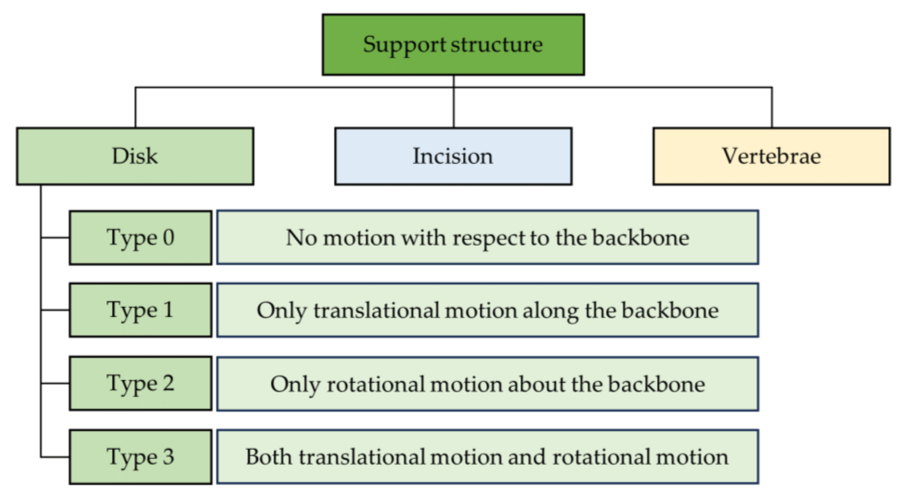
4.3. Fabrication of TDCR Support Structure

The support structure is a crucial component for elastic backbone CMs, serving to define the peripheral shape of the CM, guide driving tendons, create a secure path for signal and power cords, accommodate flexible tools, and contribute to determining the number of degrees of freedom (DOFs) in a TDCR. The support disks, often referred to as spacers or spacer disks, can be categorized into three types: (1) disk, (2) incision, and (3) vertebrae structures, as classified in Figure 11.
Disk structures can be further categorized based on their motion freedoms concerning the backbone, as outlined in [162]. These disks are attached as follows: (1) Type-0, where no motion is possible [122]; (2) Type-1, where only translation along the backbone is possible [126]; (3) Type-2, where only rotation is possible [162], and (4) Type-3, where both translation and rotation are allowed [162]. Researchers have demonstrated the potential for integrating Type-3 disks for a single-section CM design in [162]. A Type-3 disk can exploit all four degrees of freedom (DOFs) for a single-section TDCR, encompassing two bending, one translation in the form of extension/compression, and one twist about the longitudinal axis. The support-attachment method should have minimal impact on Young’s modulus and other mechanical properties to maintain model accuracy and prototype precision [122,126,162]. The incorporation of a high number of spacer disks helps ensure the tendons assume a continuous, smooth bending shape [125]. However, the more the number of disks attached, the greater their influence on the model, as it affects the mechanical properties of the CM.
The supports can take various forms, including tubes, and disks/plates of various shapes [126]. Circular disks are commonly chosen as the typical profile in most works. However, specialized designs adopting non-circular support structures also exist [160,161,180]. Figure 12 illustrates various possible shapes for preparing support disks where Figure 12a to Figure 12e show a circular disk with centre hole(lumen) for accommodating signal transmission cables, a basic circular-type solid-support disk, tri-arm disk, cross-arm disk, and a solid-square disk, respectively. These different options could be considered for weight optimization of the TDCR. However, in general, there is no difference when it comes to the function, as all of the designs provide uniform radial distribution of tendons around the centreline. For fabricating disks, a variety of material options are available in the research community, such as nylon, low-friction thermoplastic [121], Teflon (Polytetrafluoroethylene)-rich delrin (Polyoxymethylene) plastic [122], aluminium [126,162], polylactic acid (PLA) [151], etc. Teflon-rich delrin plastic is excellent for reducing friction between tendons and disks at the eyelet.
When dealing with multiple sections in a CM, eyelets (tendon routing holes) are primarily inserted depending on whether tendons for multiple sections are taken through the same path or not. While some works employ the same path of tendon routing, others recommend having separate routing paths to avoid the entangling of tendons [125]. Figure 13a shows the method of taking the tendons through dedicated paths while they stay along the same radius at different offsets [181]. Figure 13b depicts a method of taking tendons through different paths aligned at different angles at different offsets and Figure 13c shows a way of taking all the tendons through the same path. Providing different centre offsets for the tendons of each section can ensure that the tendons are not tangled. Using separate paths can also reduce the loss in the tendon effort provided by the driving actuators. The support structure is typically laminated with a flexible medium in environments where the manipulator’s application is complex. Common lamination mediums include silicone [167] and steel wire mesh [134], etc. However, these materials should be close enough to be homogeneous and not significantly affect the mechanical properties of the CM [182].

Perspectives on TDCR Support Structure

As discussed in Section 1.2 and Section 4.2.4, the weight and moment of inertia of the CM should be minimal for optimized energy consumption and system control of the CAAMS. However, the support structure can also influence the weight of the CM and moment of inertia. This could be addressed by optimizing the weight of the support structure against the required strength. Furthermore, designing the support structure with variable diameter supports that decrease in diameter from the base of the CM to the tip can reduce the moment of inertia of the CM. Moreover, the support structure also plays a key role in producing friction on the driving tendons, which, if not addressed, can result in low accuracy in system control of the CAAMS.
The fabrication of a continuum manipulator (CM) with Type-0 supports is straightforward, and the design, manufacturing, and control aspects of CMs with Type-0 supports are well-evolved. In contrast, Type-3 supports offer versatility in terms of degrees of freedom (DOF) and actuator reduction possibilities, but their integration and control strategies require further analysis and development. As discussed in the backbone preparation section, the number of supports per unit length involves a trade-off between position accuracy and friction loss of actuation force [122]. During the design phase, the user must prioritize these factors. Techniques such as using self-lubricating materials like Teflon-rich plastic sheets for support preparation and applying Teflon coating on tendons and eyelets can reduce friction. In a multi-sectioned CM, providing separate eyelets for each section is recommended to avoid tendon entanglement and reduce friction, though this introduces challenges in tendon slack control.
As the aerial manipulators are expected to be working in complex and irregular environments, there is a high probability of getting stuck with the objects in the environment. To address this issue, encapsulating the volume of the whole manipulator body surface with a flexible medium like a silicone sheath is desirable. However, the encapsulation medium should maintain consistent mechanical properties under varying environmental conditions, especially when aerial manipulation is performed in open spaces under the sun or in industrial plants, which can cause significant temperature variations. Any deviation can impact the accuracy of the CR, causing a change in overall stiffness from the designed values. This can further affect the manipulation accuracy of the aerial manipulator.
Another critical challenge in assembling supports with the backbone is ensuring that the supports are aligned in a straight line and that their faces are perpendicular to the backbone. An assembly track, as proposed in [183] is recommended for ease of support assembly with the backbone and tendon routing. Figure 14 shows an enhanced version of this method proposed by us. The assembly aid ridge and the assembly aid cut are aligned together to hold the disks in same orientation to align the eyelets. This enables rightly organized disks for the ease of assembly of the disks, tendons, and the backbone together.

4.4. Preparation and Methods of Tendons

4.4.1. Tendon Pairs

The fundamental role of tendons in a CM is to provide basic stiffness and orient the CM as needed. As tendons cannot provide a pushing force, they should always be under tension to keep the CM stiff. Tendons need to be suspended at the last support of the particular section, typically at the tip of the manipulator, by means of attachment, which can be as simple as a knot. There are different options available for determining the number of tendons and actuators needed to drive a single section of a CM: (1) four tendons per section, (2) three tendons per section, and (3) one tendon per section.
When a CM section is actuated to achieve bending, the displacement on the external tendon, outside the bending curve, increases, while the internal tendon should decrease appropriately to prevent slack. Various actuation arrangements can achieve this. The optimal option might be using individual actuators for each tendon. However, some research has proposed using a single actuator for antagonistic tendon pairs [167,169]. In a four-tendon CM section, achieving planar bending is ideally conducted by actuating an antagonistic pair. In a three-tendon actuated section, there needs to be coordination among all three tendons to actuate for any orientation. Four-tendon or three-tendon sections can have two bending degrees of freedom. However, in the case of a single-tendon-driven design, the achievable degree of freedom is limited to one.

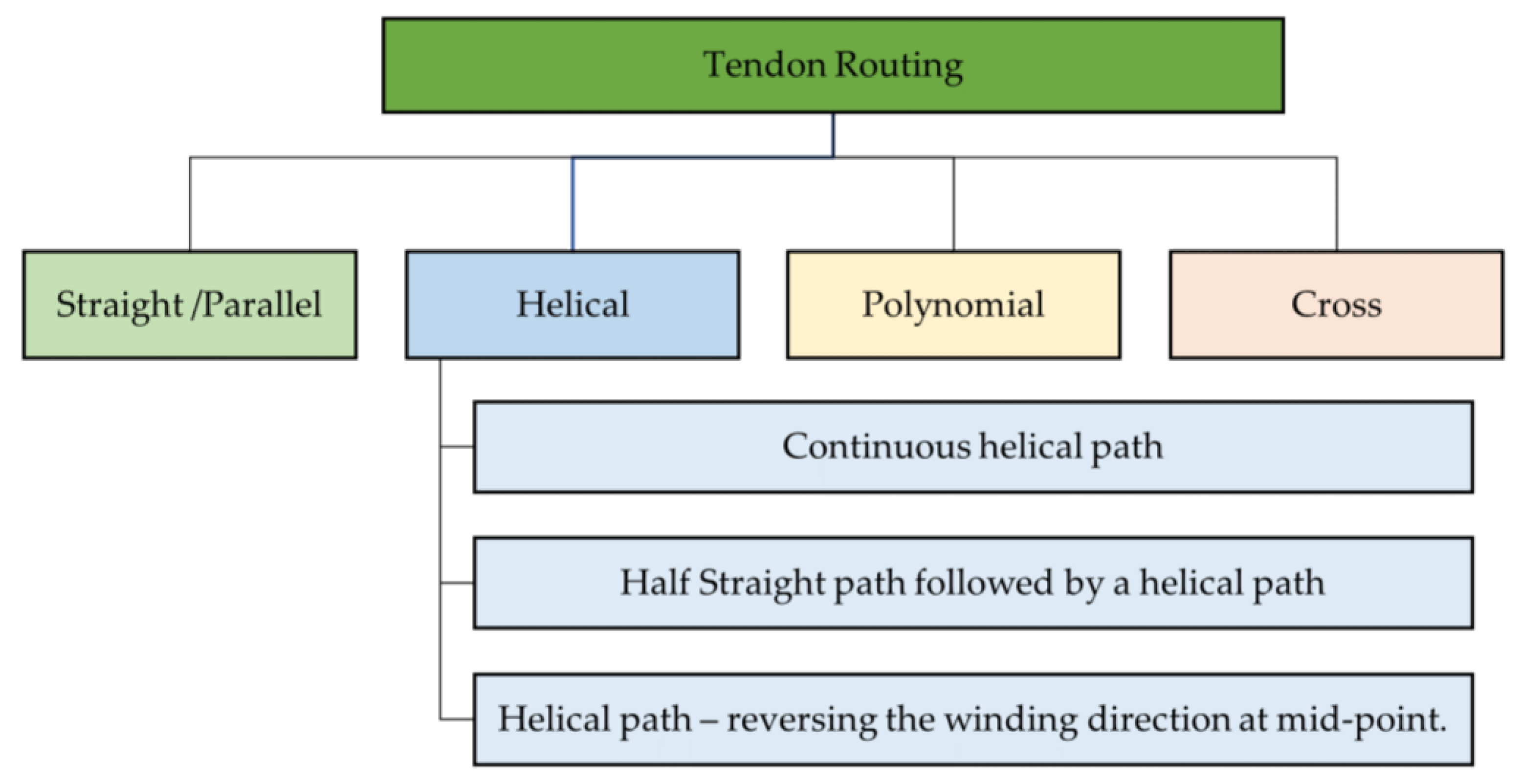
4.4.2. Tendon Routing Methods

Tendon routing is accomplished in various ways, which can be categorized as straight tendon routing (STR), helical tendon routing (HTR), or polynomial tendon routing (PTR). Different tendon routings apply wrenches along the manipulator, significantly influencing the tip orientation ability and enabling the achievement of various shapes within a one-section CM [121,122,123]. Figure 15 shows the different tendon routing methods followed.
In contrast to straight tendon routing (STR), helical/polynomial tendon routing (HTR) can provide a parallel tip orientation at various positions on a plane. D. Caleb Rucker and Robert J. Webster III have investigated the effects of STR, HTR, and PTR, employing a coupled modeling approach using classical Cosserat rod and Cosserat string models. Essentially, HTR can be achieved by making a tendon complete one turn around the backbone as it travels from the start to the end position. Mathematically, HTR and PTR are represented in sinusoidal form (sine or cosine) along two orthogonal directions (X-direction and Y-direction) on the plane perpendicular to the straightened backbone (Z-direction) [121,122]. One of the critical design parameters for tendon routing is the eyelet (the hole on the support disk for tendon routing) position with respect to the central backbone.
The optimum eyelet position for keeping a constant curvature model is found to be 0.4 of a non-dimensional length, which is the ratio between the eyelet’s normal distance (offset) and the segment length (space between two consecutive supports). These design parameters have been employed in the works [122,124].
Ref. [121] demonstrated that integrating a helical tendon, in addition to three straight tendons in a single-section CM, can increase the reachable workspace by four times, and 2.5 times for a two-section CM, improving dexterity. This improvement is compared by having straight tendon routing for the same CM. The reason for the improvement of the workspace is explained as the ability to provide torsional displacement to a CM by means of helical tendon routing, while straight tendons provide bending motion. In this work, they investigated helical tendon routing through three different methods: (1) continuous helix around the backbone, (2) a straight path followed by a helical path, and (3) a continuous helical route that reverses its direction at the midpoint. It should be noted that as the tendon completes more turns around the backbone in a helical path, the actuator must exert greater torque, leading to increased torsion on the backbone. Furthermore, the eyelet height and backbone length are found to be parameters affecting the exerted moment and the robot’s response.
Ref. [121] identified several helical tendon routing design variables that impact the actuation force requirement for achieving a specific amount of deflection. The method of tendon routing is the key variable that determines the shape of the deflection of a CM. Design variables of helical tendon routing are:
  • Continuous helix or partial helix;
  • Direction of helix (single/mixed);
  • Eyelet height;
  • Number of turns;
  • Initial routing angle and ending angle;
  • Helix angle;
  • Backbone length;
  • Method of routing.

4.4.3. Selection of Tendons

When selecting tendons for a continuum manipulator, it is crucial to consider the maximum force that the manipulator would induce on a single tendon. Additionally, the tendons should have low extension under applied forces to prevent undesired shape deviations. To achieve this, it is advisable to choose tendons with high tensile strength to withstand significant forces and a high Young’s modulus to ensure minimal extension [126]. One needs to estimate the maximum force that the designed CM would need to handle and select the desired tendon. In practical applications, tendons for continuum manipulators are often made from braided threads composed of ultra-high molecular weight polyethylene (UHMWPE) fibers [126], nylon [184], fishing line [166], Teflon-coated fiberglass thread [122], steel wire [135], and Tungsten cables [134]. For braided threads, researchers have utilized various commercially available options, including Dyneema® [151], Nanofil®, Fireline® [167], Spectra Fiber® [162], and Kevlar®. In the study [126], researchers investigated the available options for braided threads and found that Spectra Fiber® outperforms the other in terms of the Young modulus and constant linear behaviour of stress against strain. Still, one can decide the suitability based on the application in hand.

4.4.4. Avoiding Friction

In the context of reducing friction between tendons and support structures, different methods have been explored. For instance, Teflon-filled delrin plastic was used by [122] to minimize friction at the tendon-eyelet interface. Another approach involves applying a Teflon coating on tendons using a Teflon spray [121]. Tendons can also be routed through a sheath or flexible tube to decrease interaction with the environment or other system components [158]. However, it is essential to note that while these methods reduce friction, they may also impact the useful effort from the actuator.

4.4.5. Actuator Reduction Techniques along Side of Tendon Configuration

As discussed in the initial sections, the weight of the continuum manipulator, weight to payload ratio, and compactness and miniaturization are some of the critical aspects for adopting CMs for aerial manipulation. A significant amount of weight and the actuation compartment space of TDCRs are from the actuation motors. It will be beneficial if one can reduce the number of actuators required for achieving the same manipulability and dexterity. However, it should be noted that while actuation reduction strategies provide advantages in weight and compactness, they can add additional challenges in terms of modelling and control. Several strategies have been explored in research to reduce the number of actuators in continuum manipulators. These strategies include: (1) using single motor-driven antagonistic tendon pairs [124,183,184,185], (2) cross-tendon routing [153,185], (3) helical tendon routing [121], and (4) use of locking mechanisms [166]. Table 4 presents specimen examples for various methods that enable reductions in actuator demand while empowering the motion space.

Technique 1: Driving an Antagonistic Tendon Pair

Driving an antagonistic tendon pair using a single motor can drive the CM for bending in one plane. Two such motors can drive the tendon in two orthogonal planes, thus achieving a spatial motion. In this approach, the proximal end of each tendon of the pair is wound in opposite directions around a pulley connected to a motor. When bending takes place, this winding method facilitates winding, such that one tendon is unwound while the other is further wound. However, in this method, there is a potential issue of tendon entanglement within the pulley.
To mitigate the risk of tendon entanglement, a practical solution involves designing the driving pulley with two separate grooves or tracks [185]. Each tendon of the pair is then wound on its dedicated groove, ensuring independent motion, and preventing entanglement. This design enhancement maintains the efficiency and functionality of the antagonistic tendon pair system, while addressing potential complications. Note that driving the antagonistic tendon pairs using individual actuators is described in the section ‘Methods—Tendon Routings’. Single motor-driven antagonistic tendon pairs can result in an actuation pack with half the number of actuators, as opposed to a four-tendon per section CM manipulator that operates in the 3D space. This can potentially reduce the form factor, weight, and increased power to weight ratio of the system which can positively impact the adaptation of CMs in mobile robotic applications.
When utilizing a single motor to drive both tendons of the antagonistic pair, a core challenge is preventing tendon slackening while ensuring synchronized operation. The equations for designing such a driving system, incorporating the tendon slackening condition from [183], are presented below along with a graphical explanation. To address tendon slackening, one can implement a tendon slack prevention system, like the solutions proposed by [137,183]. In these designs, each tendon travels over a pulley connected to a tensioning spring, which applies tension to the tendons. If slack occurs, the tensioning springs work to reduce it. Additionally, proper control systems with feedback using IMU sensors mounted on the manipulator and torque sensors can be employed to compensate for tendon slack [39].

Technique 2: Cross-Tendon Routing

Making use of cross-tendon routing of antagonistic pairs can generate an S-curve in a 2D plane, thereby reducing the actuator requirement by one fourth compared to parallel tendon routing driven by individual motors. In the research [153,185], the antagonistic tendon pair swaps their paths midway through by crossing the backbone either through supports [185], or by avoiding the support and directly penetrating through the backbone [185]. This method produces bending in opposite directions when a tendon is pulled. Furthermore, [185] demonstrated that distributing the disks at various positions can not only produce constant curvature but also variable curvature bending. Therefore, this method can help reduce the additional use of actuators per S-curve.

Technique 3: Using Locking Mechanism

Locking mechanisms implemented at the midpoint of CMs are employed to change the direction of bending in a series. First, obtaining the C-curve bending and activating the locking of half the length of the CM is conducted. As a result of this, the section up to the locking mechanism will become stiff. Secondly, the pulling method is adjusted among the tendons to achieve the S-shape in the desired direction either in the 3D or 2D working space. Researchers have presented various locking mechanisms, including a magnetic locking mechanism that reduces the actuator requirement by a factor of two [166], friction-based locking mechanisms that utilize SMA-based stimulation for activating the friction mechanism [186], fluid chambers for activating friction lock [187], clutch mechanism-based locking activated by SMA [188], mechanical locking [163,189], and pneumatic locking [190].

Technique 4: Helical Tendon Routing

Making use of one helical tendon routing in conjunction with three straight tendon routings can produce an S-curve within a single section. Here, the actuator requirement is reduced from six actuators for two sections that produce an S-curve to four actuators that produce an S-curve within one section [121].

4.4.6. Perspectives on Tendons

The addition of a helical tendon to a three-straight tendon-actuated CM introduces versatility in generating curves. However, it comes at the cost of increased tip position errors compared to similar manipulators with only straight tendons. Additionally, helical tendon actuation may lead to higher torsion around the CM, potentially causing mechanical vibrations during operations, which is undesirable for manipulation applications. When selecting tendon materials, options like nylon, a widely available and low-cost choice, exist. However, nylon is prone to longitudinal creep. Microfiber threads offer better performance and endurance against creep, but they have higher friction due to a rough surface and come at a higher cost compared to nylon. If weight, inertia, and friction are not significant concerns, steel wire ropes can be considered for their ability to handle high loads.
Various methods of actuator reduction should undergo critical examination to assess their advantages and limitations, benefiting end-users. Factors such as actuator loading, power consumption, friction, workspace, positional accuracy, and shape accuracy are crucial considerations for comparative experimental analysis. In contrast to straight tendon routing (STR), helical/polynomial tendon routing (HTR) provides a parallel tip orientation at various positions on a plane. This capability of helical tendon routing enables precise tasks, such as accurate pick and place, stamping, and inspection in industrial applications.

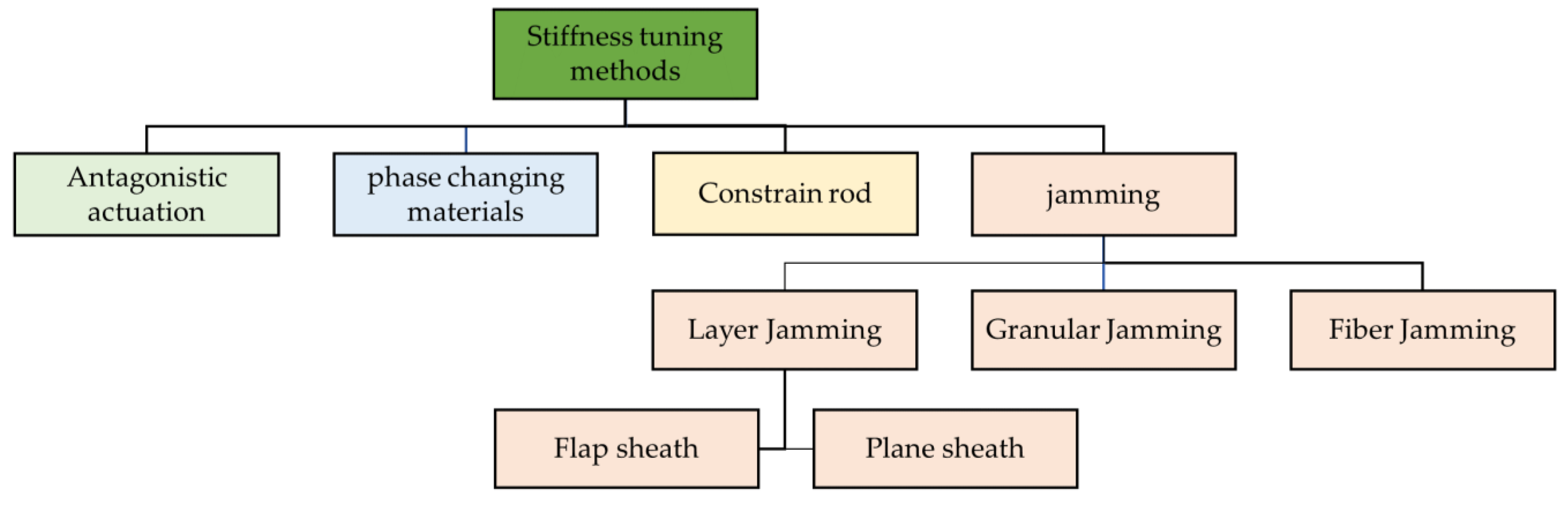
4.5. Stiffness Tuning

One of the challenges in the mass-scale adoption of continuum robots across various applications lies in their limited bending stiffness against external loads, while still maintaining their dexterity. The stiffness of a continuum robot is crucial for its load-carrying capacity. Different stiffness models and methods have been developed to address the diverse stiffness requirements imposed by various applications. Stiffness is the measure of force required to induce a unit deflection within the elastic range of a medium. It can be assessed in different directions relative to the robot’s anatomy or motion direction, including axial, transverse, and rotational stiffnesses. Each type of stiffness is determined by various factors. Table 5, in conjunction with Figure 16, outlines various methods of adjusting stiffness and their respective procedures. The Table 6 outlines specimen examples of different stiffness variation methods.
In the design standpoint, stiffness variation can be implemented either during the initial design phase or dynamically during operation at the control level, through the control of actuation. Design-stage stiffness variation involves pre-defining the structure of the continuum robot (CR) to achieve a specific stiffness, with the robot’s parameters determined accordingly. On the other hand, stiffness changes during operation can be achieved through various mechanisms, such as actuation of antagonistic tendon pairs, the curvature-constraining rod method [150], using phase changing materials [191,192], and jamming methods [146,157,193,194]. When an application requires a significantly larger length of CM with a better stiffness, a cooperative continuum manipulation approach could be adopted to modulate the stiffness. In this proposed method, the main CM, which is acting as the operator CM, is supported by the means of additional CMs which act as supports [195].
Table 6. Specimen examples of TDCRs that employed various stiffness tuning methods.
Ref.Stiffness DirectionMethodMaterial UsedRemarksExternal/Internal to the CM BodyApplication
[196]TransverseRods as driving means
  • NiTi rods for backbone and secondary backbones.
  • Increasing the secondary backbone numbers, increases the stiffness but not in a linear way.
[150]TransverseCurvature-constraining rod
  • NiTi redundant backbones, and highly stiff rod.
  • The stiffness increased by a factor of 4.71.
[197]TransverseCurvature-constraining rod
  • Steel tube as constraining tube inside a silicone tube.
  • Actuation: curvature constraining tube is actuated by stepper motor.
MIS instruments
[157]Transverse and axial directionsLayer jamming
  • Stiffening flap sheath made of transparent plastic sheets.
  • Actuation: motors.
  • Concept validated.
External surface that only packs the backbone while tendons are lying outside.Space
[193] Layer jamming and Grannular jamming
  • Stiffening flap sheath: synthetic fiber paper (two side-coated Neobond and Tyvek).
  • Coffee granule
  • Actuation: Vacuum pump.
  • Stiffness was improved by a range of 9.75–24 times using the flap method.
External surfaceMedical
[146]Transverse and axial directionsLayer jamming sheath, vacuum pressure-driven
  • PVC Sheet
  • Stiffening flap sheath
  • Approximate models are developed.
  • Transverse stiffness increased by a factor of 6.6 and axial stiffness increased by a factor of 207.8.
External surfaceMIS
[194]Transverse Granular jamming
  • Coffee powder filled in a latex cover (latex thickness: 0.25 mm)
  • Coffee powder showed good stiffening capabilities (low weight, fast stiffness change, high stiffness ratio).
  • Latex covering provided combination of high extensibility and durability.
Internal jamming. Only packs the backbone spring.N/A
[198]TransverseGranular + layer jamming (hybrid)
  • Granules: sucrose (best), lactose, collagen, and coffee.
  • Encapsulation: latex
  • Flap material: synthetic fiber paper (two side-coated Neobond and Tyvek).
  • Relatively highweight observed.
  • Partial particle jamming during manipulator steering happened.
External surfaceMIS
[199] Granular jamming, layer jamming, hybrid jamming
  • Rigid granules: matte-surfaced glass beads.
  • Deformable granules: polystyrene packing beads.
  • Negative pressure, provided by a vacuum pump.
  • Encapsulation: Latex sheath.
  • Actuation: vacuum pump
  • Factors of CM evaluated:resisting force, positional accuracy, bending diameter, deformation under external forces, cylindrical density, and activation time
Comparative study
[191]TransverseSMA
  • SMA Spring on NiTi driving rod.
  • A 300% increase in stiffness was reported. This was achieved by applying varying force on driving rods of CM by means of a winding applied on them.
Internal

4.5.1. Jamming-Based Stiffness Tuning

Some works conceived and demonstrated the feasibility of different jamming methods, giving priority to layer jamming using double flap sheaths [146,157,193], granular jamming involving various particles [193,194], and hybrid designs that combine layer jamming and granular jamming [198]. When incorporating stiffness-tuning methods into a continuum manipulator (CM), it is crucial to assess the performance of the stiffness-tuning mechanism alongside the evaluation of the CM. Clark and Rojas [199] proposed five metrics for evaluating the stiffness-changing mechanism, as outlined in Table 7.
According to Clark and Rojas, the evaluation between six combinations of various jamming possibilities using granular jamming, layer jamming, and hybrid jamming through granular and layer compositions resulted the following findings [199]:
  • Layer jamming provides a fast response for both activation and deactivation;
  • Hybrid approaches are the best for resistant force-oriented functions;
  • Granular jamming using deformable granules is the slowest in response to activation and deactivation.
It is evident that the jamming materials and methods are still under investigation. Among the materials used for layer jamming, researchers have commonly selected flexible plastic sheets [157], polyvinyl chloride film [146], Mylar (polyethylene terephthalate) sheets [199], and synthetic fibre papers such as Neobond® and Tyvek® [193,198]. Notably, synthetic fibre papers have demonstrated better performance compared to general flexible plastic sheets [193].
For granular jamming, a range of particles has been employed, including matte-surfaced glass beads, polystyrene packing beads, coffee, sucrose, lactose, collagen, and more [194,198,199]. Sucrose, in particular, has shown superior performance in the context of medical applications [198]. Howard et al. investigated 35 various grains which included a mix of commercially available substances and 3D printed granules for their suitability for use as a granule and created a dataset [109]. They considered the variability among the grains in terms of shape, size, and softness. The work mainly explored the gripping capability and shock-absorbing capacity provided by the grains when used as jamming materials and produced a comprehensive table of data. These data can be highly beneficial in designing stiffness tuning. The study further suggested that soft grains are suitable for gripping applications, whilst large-rigid grains can work well for shock absorption. This finding can be applied to jamming-based stiffness tuning applied to CMs in CAAMSs, where the possibility of vibration and impact are high. Table 8 summarises the important properties that one should consider when selecting materials for layer- or granular-based jamming.
Various studies have favoured coffee particles for granular jamming. The prevalent method involves utilizing a vacuum pump to compress layers or particles within an airtight, flexible chamber to achieve different stiffness levels. However, an alternative approach was explored by [157], where mechanical force generated by motors was employed to control double flap sheath-based layers. In this design, the flaps are connected via a thin spring winding over the backbone, which is composed of a stiff spring.
In certain designs, the jamming structure also partially serves as the backbone, with support disks attached at the structure’s terminal. These support disks facilitate the paths for the tendons. When the continuum robot is designed with multiple sections, these sections are connected using support disks. Tendons are radially routed around the jamming structure. However, there are innovative designs that conceptualize a TDCR equipped with stiffening sheaths as an external surface. In such designs, the entire continuum structure is enclosed within the stiffening sheath [146,193]. Researchers proposed a layer jamming-based method, along with a stiffness model derived from the Euler–Bernoulli beam theory [146]. This method is capable of controlling stiffness in both transverse and axial directions.

4.5.2. Curvature-Constraining Rod-Based Stiffness Tuning

Research on stiffness variation in multi-backbone continuum robots has proposed methods using the Euler–Bernoulli beam theory alone [150], or a combination of Euler–Bernoulli beam theory and screw theory [200]. The work [150] concentrated on a two-section multi-backbone CR and [197] worked on a serpentine-type multi-link backbone TDCR using a method called curvature-constraining rod for stiffness changing. These research efforts proposed a method using a length-adjustable push-pull rod termed a ‘curvature-constraining rod’, and [150] showed that the stiffness is enhanced by a factor of 4.71. By changing the effective length of the constraining rod, which is concentrically pushed inside the flexible portion, the resultant flexible length and effective stiffness of the flexible section and curvature of the CR are changed as well. The curvature-constraining rod can be actuated using a motorized carriage mechanism aided by a lead screw.
The impact of structural variation on stiffness at the design stage was explored in [196,200]. Secondary backbones are typically chosen as flexible rods, enabling the CR to be actuated by pushing and/or pulling. Studies have demonstrated that passive (unactuated) secondary backbones can also enhance stiffness [150,196]. It was revealed that transverse stiffness can be scaled up by increasing the number of secondary backbones; for instance, increasing secondary backbones by a factor of six can increase stiffness by a factor of four [196]. Further, [200] modelled various stiffnesses of a single-section, multi-backbone CR and experimentally evaluated and demonstrated an accuracy level of 93%. The resulting equations are valuable for modelling multi-backbone CRs for control purposes.

4.5.3. Thermomechanical Effects-Based Stiffness Tuning

Researchers have employed the thermo-mechanical effects of shape memory alloy (SMA) wires to control stiffness [191,192]. SMAs can alter their mechanical properties by transitioning between martensite and austenite states when exposed to thermal energy. The heat necessary for this transformation is generated by passing electricity through the SMA. Essentially, a winding applied around a rod can experience different friction forces as the wind tightens with varying forces. This varying friction can be correlated with stiffness through the work–energy principle [192].
In [191], a NiTi rod-driven robot prototype was developed, where the driving rods were wound with cotton ropes at the points of backbone supports. These windings were actuated by SMA wires, allowing for the variation of tightness and, consequently, the stiffness of the driving rods. This demonstrated that a change in stiffness was possible, with a maximum increase of up to 300%. In another study, researchers applied multiple sets of SMA windings directly on a rubber tube containing a central backbone and radially arranged secondary backbones. Activation of the SMA windings altered the friction between the secondary backbones and the rubber tube, resulting in a change in stiffness, with a demonstrated maximum increase of 140% [192].

4.5.4. Perspectives on Stiffness Tuning

In the context of aerial manipulation, the variability of a CM’s stiffness can be beneficial for increasing load-handling capability, exhibiting adaptable compliance with the environment when maneuvering through complex paths, and reducing oscillation during the UAV’s free flight. Moreover, stiffness-tunable multiple CMs can act as landing gears for the UAV, allowing for safe perching on irregular terrains. Some methods of stiffness tuning can add large weight and inertia to the CM system, which is not preferable for aerial manipulators. For example, layer jamming and particle jamming methods, which utilize pneumatic power, require extra components for controlling the air supply and consume additional power. Stiffness tuning methods using controllable flexure hinges installed radially around the backbone between consecutive supports could be a good choice in high load-handling aerial manipulation tasks [148].
Future research in jamming-based stiffness tuning methods should provide design standards covering material selection, fabrication standards, improved evaluation metrics and methodologies, and a general criterion for matching various stiffness tuning methods with potential applications. Moreover, current methods report experiment-based results, however researchers need to come up with stiffness design methodologies which can provide a relationship between the stiffness value demanded by the application and the relevant element design. Awareness of the limitations and advantages of each jamming method is crucial when utilizing them for different applications, as highlighted in review articles [80].
For curvature-constraining rod-based stiffness control, it is important to acknowledge that the robot loses its bending ability at the mid-portion where the curvature-constraining rod corresponding to the second section occupies its home space. This limitation might impact applications requiring high flexibility for path-following motion in unstructured environments. Nevertheless, this method can be advantageous due to its ease of control and suitability for multi-link backbone TDCR (serpentine) robots [197]. Additionally, the non-linear relationship between the number of secondary backbones and the stiffness increment should be considered, attributed to the radially arranged backbones leading to varying loading on individual backbones when a non-parallel load is applied [200].
The utilization of thermomechanical effects for stiffness variation has its limitations, mainly related to activation and deactivation time. While the activation due to Joule heating is faster, the extended time required for cooling down under convection after activation may not be ideal for manipulation systems where high speed is desired (actuation cycles faster than 0.1 Hz are typically not possible with thermomechanical systems). Moreover, the introduction of active cooling systems can increase the system’s complexity and control. Despite these challenges, if the aforementioned challenges are addressed, this method could be a promising approach for intrinsic, local stiffness variation, offering significant benefits for driving CMs through complex paths.

4.6. Common Causes of Errors and Calibration

Errors can be viewed as modelling errors, system fabrication-related errors, and measurement errors. Fabrication-related errors and modelling errors directly affect the accuracy of tip position and the shape of the CR, while the measurement errors will be challenging in the calibration of the system for its tip errors and shape errors. Errors in evaluating a prototype against the simulation model can arise from higher applied loads or tendon forces, increased friction loss due to the higher tendon load, measurement inaccuracies, and changes in tendon routing accuracy.

4.6.1. Errors

Modelling-based errors mainly arise from assumptions and simplifications. Assuming the backbone starts normal to the base support can introduce errors because, there may be clearance between the backbone and the centre hole of the base support which can cause a non-perpendicular profile between them [122]. Further, the effective stiffness of the backbone can vary due to the attachment methods of supports such as crimps, adhesives, and welding, etc. [122]. In the case of an extensible CM with a concentric tube backbone and multiple sections, the summation of elongation of tendons in all sections can lead to significant position or shape errors. Furthermore, [126] discussed three various elongation possibilities of threaded tendons that can affect overall accuracy: (1) elastic elongation, (2) plastic elongation, and (3) hysteresis. Routing the tendons of multi-section robots through the same path can also cause errors due to friction between the tendons [126]. Friction between tendons and supports can be addressed through modelling, or by applying friction-reducing substances like Teflon coating.
Small differences in the angular orientation measurement of the backbone at the bottom can lead to significant errors in the tip position estimation. Additionally, the effective stiffness of the backbone can vary due to attachment methods of supports, such as crimps, adhesives, and welding, etc. Measurement inaccuracies occur during the collection of point clouds using optical means and the estimation of shape from the collected points [121,162], as well as tendon force measurement [162]. The ultimate effect of errors is reflected in the tip position and shape of CMs. Position error is represented as the ratio between the deviation of the actual position of the CM’s tip from the target and the total length of the CM. To measure shape error, area-based methods have been proposed [162]. The method involves calculating the area covered by the projection of the robot’s volume when deployed to navigate through a path. Errors are typically presented as a percentage of the CM’s dimensions. When adopting a specific design for any application, including research works, users must consider the magnitude of the error that would be present in the newly built system with scaled dimensions.

4.6.2. Calibration

To account for the errors, the CM system should be calibrated for the Young’s modulus [121,122,162], accommodating friction through the estimation of coefficient of friction [162], and the three Euler angles that express the orientation of the CM’s base frame [122,162]. D. Caleb Rucker and Robert J. Webster III utilized an ‘unconstrained non-linear optimization problem’ for finding the parameter values that diminish the tip position errors [122]. For this purpose, a set of experiments on the prototype were performed and the output data used. They utilized the Nelder–Meade simplex algorithm i through MATLAB’s fminsearch function for solving the optimization problem. Care should be taken when choosing the measurement system and the shape estimation algorithm, in terms of measurement accuracy and least count. The tendon routing accuracy arose since the tendons are considered continuously curved in the model, but they are piecewise straight lines in the prototype. This error can be minimized by reducing space between the two consecutive supports.

5. Conclusions

This literature survey article aims to serve as a comprehensive resource summarising the current progress of CAAMS research and the fabrication aspects of the most common continuous backbone TDCRs and multi-link backbone TDCRs from the perspectives of a CAAMS. The summary is derived from a thorough study of relevant research literature on CAAMSs and TDCRs that explicitly provides fabrication details. The paper systematically covers the publications on CAAMS, and the fabrication aspects of TDCRs. Under the fabrication of TDCR, (1) backbone, (2) support structure, (3) tendons, (4) stiffness tuning, (5) errors, and (6) calibration are discussed. From an engineering perspective, this work supports engineers and researchers to explore the potential of continuum robots for real-world applications, with the focus on the application for aerial manipulation systems. The core objective is to offer a single-point reference on fabrication of TDCRs for those working on control, planning, navigation, and integrating TDCRs into aerial manipulation and other new real-world applications. This allows them to reproduce or adopt existing TDCR designs without starting from scratch. The article aims to be beneficial for the continuum of robot research and the development community, complementing existing surveys like the one on concentric tube continuum robots (CTRs) [68].

Author Contributions

A.U.: conceptualization of the review, gathering information from the literature, writing, editing, and final checking. F.V.: conceptualization of the review, collecting literature, writing, and editing. A.J.: collecting literature, writing, and editing. K.M.D.: collecting literature, writing, editing, and paper improvement. F.J.-S.: collecting literature and editing. F.G.: supervision, conceptualization of the review, collecting literature, writing, and editing. All authors have read and agreed to the published version of the manuscript.

Funding

This research received no external funding.

Conflicts of Interest

The authors declare no conflicts of interest.

References

  1. Nooralishahi, P.; Ibarra-Castanedo, C.; Deane, S.; López, F.; Pant, S.; Genest, M.; Avdelidis, N.P.; Maldague, X.P.V. Drone-Based Non-Destructive Inspection of Industrial Sites: A Review and Case Studies. Drones 2021, 5, 106. [Google Scholar] [CrossRef]
  2. Messina, G.; Modica, G. Applications of UAV Thermal Imagery in Precision Agriculture: State of the Art and Future Research Outlook. Remote Sens. 2020, 12, 1491. [Google Scholar] [CrossRef]
  3. Kim, J.; Kim, S.; Ju, C.; Son, H.I. Unmanned Aerial Vehicles in Agriculture: A Review of Perspective of Platform, Control, and Applications. IEEE Access 2019, 7, 105100–105115. [Google Scholar] [CrossRef]
  4. Daud, S.M.S.M.; Yusof, M.Y.P.M.; Heo, C.C.; Khoo, L.S.; Singh, M.K.C.; Mahmood, M.S.; Nawawi, H. Applications of drone in disaster management: A scoping review. Sci. Justice 2022, 62, 30–42. [Google Scholar] [CrossRef] [PubMed]
  5. Asadzadeh, S.; de Oliveira, W.J.; de Souza Filho, C.R. UAV-based remote sensing for the petroleum industry and environmental monitoring: State-of-the-art and perspectives. J. Pet. Sci. Eng. 2022, 208, 109633. [Google Scholar] [CrossRef]
  6. Ding, L.; Zhu, G.; Li, Y.; Wang, Y. Cable-Driven Unmanned Aerial Manipulator Systems for Water Sampling: Design, Modeling, and Control. Drones 2023, 7, 450. [Google Scholar] [CrossRef]
  7. Villa, T.F.; Gonzalez, F.; Miljievic, B.; Ristovski, Z.D.; Morawska, L. An Overview of Small Unmanned Aerial Vehicles for Air Quality Measurements: Present Applications and Future Prospectives. Sensors 2016, 16, 1072. [Google Scholar] [CrossRef] [PubMed]
  8. Abbas, N.; Abbas, Z.; Liu, X.; Khan, S.S.; Foster, E.D.; Larkin, S. A Survey: Future Smart Cities Based on Advance Control of Unmanned Aerial Vehicles (UAVs). Appl. Sci. 2023, 13, 9881. [Google Scholar] [CrossRef]
  9. Mohsan, S.A.; Khan, M.A.; Noor, F.; Ullah, I.; Alsharif, M.H. Towards the Unmanned Aerial Vehicles (UAVs): A Comprehensive Review. Drones 2022, 6, 147. [Google Scholar] [CrossRef]
  10. Galvez-Serna, J.; Vanegas, F.; Brar, S.; Sandino, J.; Flannery, D.; Gonzalez, F. UAV4PE: An Open-Source Framework to Plan UAV Autonomous Missions for Planetary Exploration. Drones 2022, 6, 391. [Google Scholar] [CrossRef]
  11. Serna, J.G.; Vanegas, F.; Gonzalez, F.; Flannery, D. A Review of Current Approaches for UAV Autonomous Mission Planning for Mars Biosignatures Detection. In Proceedings of the 2020 IEEE Aerospace Conference, Big Sky, MT, USA, 7–14 March 2020; pp. 1–15. [Google Scholar] [CrossRef]
  12. Holness, C.; Matthews, T.; Satchell, K.; Swindell, E.C. Remote sensing archeological sites through Unmanned Aerial Vehicle (UAV) imaging. In Proceedings of the 2016 IEEE International Geoscience and Remote Sensing Symposium (IGARSS), Beijing, China, 10–15 July 2016; pp. 6695–6698. [Google Scholar] [CrossRef]
  13. Bonyan Khamseh, H.; Janabi-Sharifi, F.; Abdessameud, A. Aerial manipulation—A literature survey. Robot. Auton. Syst. 2018, 107, 221–235. [Google Scholar] [CrossRef]
  14. Ollero, A.; Tognon, M.; Suarez, A.; Lee, D.; Franchi, A. Past, Present, and Future of Aerial Robotic Manipulators. IEEE Trans. Robot. 2022, 38, 626–645. [Google Scholar] [CrossRef]
  15. Mellinger, D.; Lindsey, Q.; Shomin, M.; Kumar, V. Design, modeling, estimation and control for aerial grasping and manipulation. In Proceedings of the 2011 IEEE/RSJ International Conference on Intelligent Robots and Systems, San Francisco, CA, USA, 25–30 September 2011; pp. 2668–2673. [Google Scholar] [CrossRef]
  16. Ng, M.; Vanegas, F.; Morton, K.; Sandino, J.; Gonzalez, F. Design and Flight Test of an Aerial Manipulator for Applications in GPS-Denied Environments. In Proceedings of the 2022 International Conference on Unmanned Aircraft Systems, ICUAS 2022, Dubrovnik, Croatia, 21–24 June 2022; Institute of Electrical and Electronics Engineers Inc.: Piscataway, NJ, USA, 2022; pp. 20–29. [Google Scholar] [CrossRef]
  17. Trujillo, M.Á.; Martínez-de Dios, J.R.; Martín, C.; Viguria, A.; Ollero, A. Novel Aerial Manipulator for Accurate and Robust Industrial NDT Contact Inspection: A New Tool for the Oil and Gas Inspection Industry. Sensors 2019, 19, 1305. [Google Scholar] [CrossRef] [PubMed]
  18. AlAkhras, A.; Sattar, I.H.; Alvi, M.; Qanbar, M.W.; Jaradat, M.A.; Alkaddour, M. The Design of a Lightweight Cable Aerial Manipulator with a CoG Compensation Mechanism for Construction Inspection Purposes. Appl. Sci. 2022, 12, 1173. [Google Scholar] [CrossRef]
  19. Zaman, A.; Seo, J. Design and Control of Autonomous Flying Excavator. Machines 2023, 12, 23. [Google Scholar] [CrossRef]
  20. Heredia, G.; Jimenez-Cano, A.E.; Sanchez, I.; Llorente, D.; Vega, V.; Braga, J.; Acosta, J.A.; Ollero, A. Control of a multirotor outdoor aerial manipulator. In Proceedings of the 2014 IEEE/RSJ International Conference on Intelligent Robots and Systems, Chicago, IL, USA, 14–18 September 2014; pp. 3417–3422. [Google Scholar]
  21. Suarez, A.; Jimenez-Cano, A.E.; Vega, V.M.; Heredia, G.; Rodriguez-Castaño, A.; Ollero, A. Design of a lightweight dual arm system for aerial manipulation. Mechatronics 2018, 50, 30–44. [Google Scholar] [CrossRef]
  22. Suarez, A.; Heredia, G.; Ollero, A. Design of an Anthropomorphic, Compliant, and Lightweight Dual Arm for Aerial Manipulation. IEEE Access 2018, 6, 29173–29189. [Google Scholar] [CrossRef]
  23. Zhang, K.; Chermprayong, P.; Xiao, F.; Tzoumanikas, D.; Dams, B.; Kay, S.; Kocer, B.B.; Burns, A.; Orr, L.; Alhinai, T.; et al. Aerial additive manufacturing with multiple autonomous robots. Nature 2022, 609, 709–717. [Google Scholar] [CrossRef] [PubMed]
  24. Chermprayong, P.; Zhang, K.; Xiao, F.; Kovac, M. An Integrated Delta Manipulator for Aerial Repair: A New Aerial Robotic System. IEEE Robot. Autom. Mag. 2019, 26, 54–66. [Google Scholar] [CrossRef]
  25. Estevez, J.; Garate, G.; Lopez-Guede, J.M.; Larrea, M. Review of Aerial Transportation of Suspended-Cable Payloads with Quadrotors. Drones 2024, 8, 35. [Google Scholar] [CrossRef]
  26. Caballero, A.; Suarez, A.; Real, F.; Vega, V.M.; Bejar, M.; Rodriguez-Castaño, A.; Ollero, A. First Experimental Results on Motion Planning for Transportation in Aerial Long-Reach Manipulators with Two Arms. In Proceedings of the 2018 IEEE/RSJ International Conference on Intelligent Robots and Systems (IROS), Madrid, Spain, 1–5 October 2018; pp. 8471–8477. [Google Scholar]
  27. Sanchez-Cuevas, P.J.; Gonzalez-Morgado, A.; Cortes, N.; Gayango, D.B.; Jimenez-Cano, A.E.; Ollero, A.; Heredia, G. Fully-Actuated Aerial Manipulator for Infrastructure Contact Inspection: Design, Modeling, Localization, and Control. Sensors 2020, 20, 4708. [Google Scholar] [CrossRef]
  28. Nicotra, M.M.; Naldi, R.; Garone, E. Taut Cable Control of a Tethered UAV. IFAC Proc. Vol. 2014, 47, 3190–3195. [Google Scholar] [CrossRef]
  29. Boukoberine, M.N.; Zhou, Z.; Benbouzid, M. A critical review on unmanned aerial vehicles power supply and energy management: Solutions, strategies, and prospects. Appl. Energy 2019, 255, 113823. [Google Scholar] [CrossRef]
  30. Robla-Gómez, S.; Becerra, V.M.; Llata, J.R.; González-Sarabia, E.; Torre-Ferrero, C.; Pérez-Oria, J. Working Together: A Review on Safe Human-Robot Collaboration in Industrial Environments. IEEE Access 2017, 5, 26754–26773. [Google Scholar] [CrossRef]
  31. Jalali, A.; Janabi-Sharifi, F. Aerial Continuum Manipulation: A New Platform for Compliant Aerial Manipulation. Front. Robot. AI 2022, 9, 903877. [Google Scholar] [CrossRef] [PubMed]
  32. Cataldi, E.; Muscio, G.; Trujillo, M.A.; Rodriguez, Y.; Pierri, F.; Antonelli, G.; Caccavale, F.; Viguria, A.; Chiaverini, S.; Ollero, A. Impedance Control of an aerial-manipulator: Preliminary results. In Proceedings of the 2016 IEEE/RSJ International Conference on Intelligent Robots and Systems (IROS), Daejeon, Republic of Korea, 9–14 October 2016; pp. 3848–3853. [Google Scholar]
  33. Suarez, A.; Perez, M.; Heredia, G.; Ollero, A. Cartesian Aerial Manipulator with Compliant Arm. Appl. Sci. 2021, 11, 1001. [Google Scholar] [CrossRef]
  34. Forte, F.; Naldi, R.; Macchelli, A.; Marconi, L. Impedance control of an aerial manipulator. In Proceedings of the 2012 American Control Conference (ACC), Montreal, QC, Canada, 27–29 June 2012; pp. 3839–3844. [Google Scholar] [CrossRef]
  35. Suarez, A.; Soria, P.R.; Heredia, G.; Arrue, B.C.; Ollero, A. Anthropomorphic, compliant and lightweight dual arm system for aerial manipulation. In Proceedings of the 2017 IEEE/RSJ International Conference on Intelligent Robots and Systems (IROS), Vancouver, BC, Canada, 24–28 September 2017; pp. 992–997. [Google Scholar] [CrossRef]
  36. Yüksel, B.; Mahboubi, S.; Secchi, C.; Bülthoff, H.H.; Franchi, A. Design, identification and experimental testing of a light-weight flexible-joint arm for aerial physical interaction. In Proceedings of the 2015 IEEE International Conference on Robotics and Automation (ICRA), Seattle, WA, USA, 26–30 May 2015; pp. 870–876. [Google Scholar] [CrossRef]
  37. Suarez, A.; Heredia, G.; Ollero, A. Lightweight compliant arm for aerial manipulation. In Proceedings of the 2015 IEEE/RSJ International Conference on Intelligent Robots and Systems (IROS), Hamburg, Germany, 28 September–2 October 2015; pp. 1627–1632. [Google Scholar] [CrossRef]
  38. Samadikhoshkho, Z.; Ghorbani, S.; Janabi-Sharifi, F. Coupled dynamic modeling and control of aerial continuum manipulation systems. Appl. Sci. 2021, 11, 9108. [Google Scholar] [CrossRef]
  39. Peng, R.; Wang, Z.; Lu, P. AeCoM: An Aerial Continuum Manipulator With IMU-Based Kinematic Modeling and Tendon-Slacking Prevention. IEEE Trans. Syst. Man Cybern. Syst. 2023, 53, 4740–4752. [Google Scholar] [CrossRef]
  40. Chien, J.L.; Leong, C.; Liu, J.; Foong, S. Design and control of an aerial-ground tethered tendon-driven continuum robot with hybrid routing. Robot. Auton. Syst. 2023, 161, 104344. [Google Scholar] [CrossRef]
  41. Samadi Khoshkho, M.; Samadikhoshkho, Z.; Lipsett, M.G. Distilled neural state-dependent Riccati equation feedback controller for dynamic control of a cable-driven continuum robot. Int. J. Adv. Robot. Syst. 2023, 20, 17298806231174737. [Google Scholar] [CrossRef]
  42. Ghorbani, S.; Samadikhoshkho, Z.; Janabi–Sharifi, F. Dual-arm aerial continuum manipulation systems: Modeling, pre-grasp planning, and control. Nonlinear Dyn. 2023, 111, 7339–7355. [Google Scholar] [CrossRef]
  43. Ghorbani, S.; Janabi-Sharifi, F. Extended Kalman Filter State Estimation for Aerial Continuum Manipulation Systems. IEEE Sens. Lett. 2022, 6, 7002704. [Google Scholar] [CrossRef]
  44. Chien, J.L.; Clarissa, L.T.L.; Liu, J.; Low, J.; Foong, S. Kinematic model predictive control for a novel tethered aerial cable-driven continuum robot. In Proceedings of the IEEE/ASME International Conference on Advanced Intelligent Mechatronics, AIM, Delft, The Netherlands, 12–16 July 2021; Institute of Electrical and Electronics Engineers Inc.: Delft, The Netherlands, 2021; pp. 1348–1354. [Google Scholar] [CrossRef]
  45. Samadikhoshkho, Z.; Ghorbani, S.; Janabi-Sharifi, F. Modeling and Control of Aerial Continuum Manipulation Systems: A Flying Continuum Robot Paradigm. IEEE Access 2020, 8, 176883–176894. [Google Scholar] [CrossRef]
  46. Szasz, R.; Allenspach, M.; Han, M.; Tognon, M.; Katzschmann, R.K. Modeling and Control of an Omnidirectional Micro Aerial Vehicle Equipped with a Soft Robotic Arm. In Proceedings of the 2022 IEEE 5th International Conference on Soft Robotics, RoboSoft, Edinburgh, UK, 4–8 April 2022; Institute of Electrical and Electronics Engineers Inc.: Edinburgh, UK, 2022; pp. 1–8. [Google Scholar] [CrossRef]
  47. Hashemi, S.H.; Janabi-Sharifi, F.; Jalali, A. Robust Global stabilization of aerial continuum manipulation systems via hybrid feedback. ISA Trans. 2023, 138, 160–167. [Google Scholar] [CrossRef] [PubMed]
  48. Samadikhoshkho, Z.; Ghorbani, S.; Janabi-Sharifi, F. Vision-based reduced-order adaptive control of aerial continuum manipulation systems. Aerosp. Sci. Technol. 2022, 121, 107322. [Google Scholar] [CrossRef]
  49. Merz, M.; Pedro, D.; Skliros, V.; Bergenhem, C.; Himanka, M.; Houge, T.; Matos-Carvalho, J.P.; Lundkvist, H.; Cürüklü, B.; Hamrén, R.; et al. Autonomous UAS-Based Agriculture Applications: General Overview and Relevant European Case Studies. Drones 2022, 6, 128. [Google Scholar] [CrossRef]
  50. Hassler, S.C.; Baysal-Gurel, F. Unmanned Aircraft System (UAS) Technology and Applications in Agriculture. Agronomy 2019, 9, 618. [Google Scholar] [CrossRef]
  51. Choi, H.-W.; Kim, H.-J.; Kim, S.-K.; Na, W.S. An Overview of Drone Applications in the Construction Industry. Drones 2023, 7, 515. [Google Scholar] [CrossRef]
  52. Koparan, C.; Koc, A.B.; Privette, C.V.; Sawyer, C.B.; Sharp, J.L. Evaluation of a UAV-Assisted Autonomous Water Sampling. Water 2018, 10, 655. [Google Scholar] [CrossRef]
  53. Morton, K.; Toro, L.F.G.; McFadyen, A. Search and Retrieve with a Fully Autonomous Aerial Manipulator. In Proceedings of the 2019 IEEE Aerospace Conference, Big Sky, MT, USA, 2–9 March 2019; pp. 1–10. [Google Scholar] [CrossRef]
  54. Walker, I.D.; Choset, H.; Chirikjian, G.S. Snake-Like and Continuum Robots. In Springer Handbook of Robotics; Siciliano, B., Khatib, O., Eds.; Springer International Publishing: Cham, Switzerland, 2016; pp. 481–498. [Google Scholar] [CrossRef]
  55. Chirikjian, G.S. Snakelike and Continuum Robots: A Review of Reviews. In Encyclopedia of Robotics; Ang, M.H., Khatib, O., Siciliano, B., Eds.; Springer: Berlin/Heidelberg, Germany, 2020; pp. 1–14. [Google Scholar] [CrossRef]
  56. Roth, B.; Rastegar, J.; Scheinman, V. On the Design of Computer Controlled Manipulators. In On Theory and Practice of Robots and Manipulators: Volume I; Serafini, P., Guazzelli, E., Schrefler, B., Pfeiffer, F., Rammerstorfer, F.G., Eds.; Springer: Vienna, Austria, 1974; pp. 93–113. [Google Scholar] [CrossRef]
  57. Anderson, V.C.; Horn, R.C. TENSOR ARM MANIPULATOR. 1968, US3497083A, 24 February 1970. Available online: https://patents.google.com/patent/US3497083A/en#patentCitations (accessed on 25 November 2023).
  58. Burgner-Kahrs, J.; Rucker, D.C.; Choset, H. Continuum Robots for Medical Applications: A Survey. IEEE Trans. Robot. 2015, 31, 1261–1280. [Google Scholar] [CrossRef]
  59. Robinson, G.; Davies, J.B.C. Continuum robots—A state of the art. In Proceedings of the 1999 IEEE International Conference on Robotics and Automation (Cat. No.99CH36288C), Detroit, MI, USA, 10–15 May 1999; Volume 4, pp. 2849–2854. [Google Scholar] [CrossRef]
  60. Walker, I.D. Continuous Backbone “Continuum” Robot Manipulators. ISRN Robot. 2013, 2013, 726506. [Google Scholar] [CrossRef]
  61. Mitros, Z.; Sadati, S.M.H.; Henry, R.; Da Cruz, L.; Bergeles, C. From Theoretical Work to Clinical Translation: Progress in Concentric Tube Robots. Annu. Rev. Control Robot. Auton. Syst. 2022, 5, 335–359. [Google Scholar] [CrossRef]
  62. Cao, Y.; Shi, Y.; Hong, W.; Dai, P.; Sun, X.; Yu, H.; Xie, L. Continuum robots for endoscopic sinus surgery: Recent advances, challenges, and prospects. Int. J. Med. Robot. Comput. Assist. Surg. 2023, 19, e2471. [Google Scholar] [CrossRef] [PubMed]
  63. Kolachalama, S.; Lakshmanan, S. Continuum robots for manipulation applications: A survey. J. Robot. 2020, 2020, 4187048. [Google Scholar] [CrossRef]
  64. Russo, M.; Sadati, S.M.H.; Dong, X.; Mohammad, A.; Walker, I.D.; Bergeles, C.; Xu, K.; Axinte, D.A. Continuum Robots: An Overview. Adv. Intell. Syst. 2023, 5, 2200367. [Google Scholar] [CrossRef]
  65. Blumenschein, L.H.; Coad, M.M.; Haggerty, D.A.; Okamura, A.M.; Hawkes, E.W. Design, Modeling, Control, and Application of Everting Vine Robots. Front. Robot. AI 2020, 7, 548266. [Google Scholar] [CrossRef] [PubMed]
  66. Angrisani, L.; Grazioso, S.; Gironimo, G.D.; Panariello, D.; Tedesco, A. On the use of soft continuum robots for remote measurement tasks in constrained environments: A brief overview of applications. In Proceedings of the 2019 IEEE International Symposium on Measurements and Networking, M and N, Catania, Italy, 8–10 July 2019; pp. 1–5. [Google Scholar] [CrossRef]
  67. Alfalahi, H.; Renda, F.; Stefanini, C. Concentric Tube Robots for Minimally Invasive Surgery: Current Applications and Future Opportunities. IEEE Trans. Med. Robot. Bionics 2020, 2, 410–424. [Google Scholar] [CrossRef]
  68. Nwafor, C.J.; Girerd, C.; Laurent, G.J.; Morimoto, T.K.; Rabenorosoa, K. Design and Fabrication of Concentric Tube Robots: A Survey. IEEE Trans. Robot. 2023, 39, 2510–2528. [Google Scholar] [CrossRef]
  69. Tang, D.; Cheng, C.; Xiao, L.; Tang, C.; Lv, X.; Wang, G. A Review on Wire-Driven Flexible Robot Manipulators. Recent Pat. Eng. 2023, 17, 37–57. [Google Scholar] [CrossRef]
  70. Li, S.; Hao, G. Current trends and prospects in compliant continuum robots: A survey. Actuators 2021, 10, 145. [Google Scholar] [CrossRef]
  71. Yang, Z.; Yang, H.; Cao, Y.; Cui, Y.; Zhang, L. Magnetically Actuated Continuum Medical Robots: A Review. Adv. Intell. Syst. 2023, 5, 2200416. [Google Scholar] [CrossRef]
  72. Du, X.; Liu, Y.; Yu, J. Magnetically driven robots for clinical treatment. In Robotics for Cell Manipulation and Characterization; Academic Press: Cambridge, MA, USA, 2023; pp. 173–199. [Google Scholar] [CrossRef]
  73. Walker, I.D. Robot strings: Long, thin continuum robots. In Proceedings of the IEEE Aerospace Conference Proceedings, Big Sky, MT, USA, 2–9 March 2013; pp. 1–12. [Google Scholar] [CrossRef]
  74. Seetohul, J.; Shafiee, M. Snake Robots for Surgical Applications: A Review. Robotics 2022, 11, 57. [Google Scholar] [CrossRef]
  75. Yang, X.; Zheng, L.; Lü, D.; Wang, J.; Wang, S.; Su, H.; Wang, Z.; Ren, L. The snake-inspired robots: A review. Assem. Autom. 2022, 42, 567–583. [Google Scholar] [CrossRef]
  76. Walker, I.D. Biologically inspired vine-like and tendril-like robots. In Proceedings of the 2015 Science and Information Conference, London, UK, 28–30 July 2015; Institute of Electrical and Electronics Engineers Inc.: London, UK, 2015; pp. 714–720. [Google Scholar] [CrossRef]
  77. Wooten, M.B.; Walker, I.D. Circumnutation: From plants to robots. In Lecture Notes in Computer Science (Including Subseries Lecture Notes in Artificial Intelligence and Lecture Notes in Bioinformatics); Springer International Publishing: Cham, Switzerland, 2016; Volume 9825, pp. 1–11. [Google Scholar] [CrossRef]
  78. Seleem, I.A.; El-Hussieny, H.; Ishii, H. Recent Developments of Actuation Mechanisms for Continuum Robots: A Review. Int. J. Control Autom. Syst. 2023, 21, 1592–1609. [Google Scholar] [CrossRef] [PubMed]
  79. Pagoli, A.; Chapelle, F.; Corrales-Ramon, J.A.; Mezouar, Y.; Lapusta, Y. Review of soft fluidic actuators: Classification and materials modeling analysis. Smart Mater. Struct. 2022, 31, 013001. [Google Scholar] [CrossRef]
  80. Dou, W.; Zhong, G.; Cao, J.; Shi, Z.; Peng, B.; Jiang, L. Soft Robotic Manipulators: Designs, Actuation, Stiffness Tuning, and Sensing. Adv. Mater. Technol. 2021, 6, 2100018. [Google Scholar] [CrossRef]
  81. Zhang, J.; Fang, Q.; Xiang, P.; Sun, D.; Xue, Y.; Jin, R.; Qiu, K.; Xiong, R.; Wang, Y.; Lu, H. A Survey on Design, Actuation, Modeling, and Control of Continuum Robot. Cyborg Bionic Syst. 2022, 2022, 9754697. [Google Scholar] [CrossRef]
  82. Simaan, N.; Yasin, R.M.; Wang, L. Medical Technologies and Challenges of Robot-Assisted Minimally Invasive Intervention and Diagnostics. Annu. Rev. Control Robot. Auton. Syst. 2018, 1, 465–490. [Google Scholar] [CrossRef]
  83. Walker, I.D.; Clemson University. Use of continuum robots for remote inspection operations. In Proceedings of the 2017 Computing Conference, London, UK, 18–20 July 2017; pp. 1382–1385. [Google Scholar] [CrossRef]
  84. Kim, J.; De Mathelin, M.; Ikuta, K.; Kwon, D.S. Advancement of Flexible Robot Technologies for Endoluminal Surgeries. Proc. IEEE 2022, 110, 909–931. [Google Scholar] [CrossRef]
  85. Da Veiga, T.; Chandler, J.H.; Lloyd, P.; Pittiglio, G.; Wilkinson, N.J.; Hoshiar, A.K.; Harris, R.A.; Valdastri, P. Challenges of continuum robots in clinical context: A review. Prog. Biomed. Eng. 2020, 2, 032003. [Google Scholar] [CrossRef]
  86. Chikhaoui, M.T.; Burgner-Kahrs, J. Control of continuum robots for medical applications: State of the art. In Proceedings of the ACTUATOR 2018, 16th International Conference on New Actuators, Bremen, Germany, 25-27 June 2018; pp. 1–11. [Google Scholar]
  87. Hu, X.; Chen, A.; Luo, Y.; Zhang, C.; Zhang, E. Steerable catheters for minimally invasive surgery: A review and future directions. Comput. Assist. Surg. 2018, 23, 21–41. [Google Scholar] [CrossRef]
  88. Gu, X.; Ren, H. A Survey of Transoral Robotic Mechanisms: Distal Dexterity, Variable Stiffness, and Triangulation. Cyborg Bionic Syst. 2023, 4, 0007. [Google Scholar] [CrossRef] [PubMed]
  89. Chirikjian, G.S. Conformational Modeling of Continuum Structures in Robotics and Structural Biology: A Review. Adv. Robot. 2015, 29, 817–829. [Google Scholar] [CrossRef] [PubMed]
  90. Webster Iii, R.J.; Jones, B.A. Design and kinematic modeling of constant curvature continuum robots: A review. Int. J. Robot. Res. 2010, 29, 1661–1683. [Google Scholar] [CrossRef]
  91. Zhu, B.; Zhang, X.; Zhang, H.; Liang, J.; Zang, H.; Li, H.; Wang, R. Design of compliant mechanisms using continuum topology optimization: A review. Mech. Mach. Theory 2020, 143, 103622. [Google Scholar] [CrossRef]
  92. Khaniki, H.B.; Ghayesh, M.H.; Chin, R.; Amabili, M. Hyperelastic structures: A review on the mechanics and biomechanics. Int. J. Non-Linear Mech. 2023, 148, 104275. [Google Scholar] [CrossRef]
  93. Shamilyan, O.; Kabin, I.; Dyka, Z.; Sudakov, O.; Cherninskyi, A.; Brzozowski, M.; Langendoerfer, P. Intelligence and Motion Models of Continuum Robots: An Overview. IEEE Access 2023, 11, 60988–61003. [Google Scholar] [CrossRef]
  94. Sadati, S.M.H.; Naghibi, S.E.; Shiva, A.; Walker, I.D.; Althoefer, K.; Nanayakkara, T. Mechanics of Continuum Manipulators, a Comparative Study of Five Methods with Experiments. In Towards Autonomous Robotic Systems. TAROS 2017; Gao, Y., Fallah, S., Jin, Y., Lekakou, C., Eds.; Lecture Notes in Computer Science; Springer: Cham, Switzerland, 2017; Volume 10454. [Google Scholar] [CrossRef]
  95. Khaniki, H.B.; Ghayesh, M.H.; Chin, R.; Amabili, M. A review on the nonlinear dynamics of hyperelastic structures. Nonlinear Dyn. 2022, 110, 963–994. [Google Scholar] [CrossRef]
  96. Saab, W.; Rone, W.S.; Ben-Tzvi, P. Robotic tails: A state-of-the-art review. Robotica 2018, 36, 1263–1277. [Google Scholar] [CrossRef]
  97. Armanini, C.; Boyer, F.; Mathew, A.T.; Duriez, C.; Renda, F. Soft Robots Modeling: A Structured Overview. IEEE Trans. Robot. 2023, 39, 1728–1748. [Google Scholar] [CrossRef]
  98. Pore, A.; Li, Z.; Dall’Alba, D.; Hernansanz, A.; De Momi, E.; Menciassi, A.; Casals Gelpi, A.; Dankelman, J.; Fiorini, P.; Poorten, E.V. Autonomous Navigation for Robot-Assisted Intraluminal and Endovascular Procedures: A Systematic Review. IEEE Trans. Robot. 2023, 39, 2529–2548. [Google Scholar] [CrossRef]
  99. George Thuruthel, T.; Ansari, Y.; Falotico, E.; Laschi, C. Control Strategies for Soft Robotic Manipulators: A Survey. Soft Robot. 2018, 5, 149–163. [Google Scholar] [CrossRef] [PubMed]
  100. Della Santina, C.; Duriez, C.; Rus, D. Model-Based Control of Soft Robots: A Survey of the State of the Art and Open Challenges. IEEE Control Syst. 2023, 43, 30–65. [Google Scholar] [CrossRef]
  101. Xu, F.; Wang, H. Soft Robotics: Morphology and Morphology-inspired Motion Strategy. IEEE/CAA J. Autom. Sin. 2021, 8, 1500–1522. [Google Scholar] [CrossRef]
  102. Wang, X.; Li, Y.; Kwok, K.W. A Survey for Machine Learning-Based Control of Continuum Robots. Front. Robot. AI 2021, 8, 730330. [Google Scholar] [CrossRef] [PubMed]
  103. Nazari, A.A.; Zareinia, K.; Janabi-Sharifi, F. Visual servoing of continuum robots: Methods, challenges, and prospects. Int. J. Med. Robot. Comput. Assist. Surg. 2022, 18, e2384. [Google Scholar] [CrossRef] [PubMed]
  104. Zhou, L.; Ren, L.; Chen, Y.; Niu, S.; Han, Z.; Ren, L. Bio-Inspired Soft Grippers Based on Impactive Gripping. Adv. Sci. 2021, 8, 2002017. [Google Scholar] [CrossRef] [PubMed]
  105. Mehrkish, A.; Janabi-Sharifi, F. A comprehensive grasp taxonomy of continuum robots. Robot. Auton. Syst. 2021, 145, 103860. [Google Scholar] [CrossRef]
  106. Russo, M.; Gautreau, E.; Bonnet, X.; Laribi, M.A. Continuum Robots: From Conventional to Customized Performance Indicators. Biomimetics 2023, 8, 147. [Google Scholar] [CrossRef]
  107. Sahu, S.K.; Sozer, C.; Rosa, B.; Tamadon, I.; Renaud, P.; Menciassi, A. Shape Reconstruction Processes for Interventional Application Devices: State of the Art, Progress, and Future Directions. Front. Robot. AI 2021, 8, 758411. [Google Scholar] [CrossRef]
  108. Shi, C.; Luo, X.; Qi, P.; Li, T.; Song, S.; Najdovski, Z.; Fukuda, T.; Ren, H. Shape sensing techniques for continuum robots in minimally invasive surgery: A survey. IEEE Trans. Biomed. Eng. 2017, 64, 1665–1678. [Google Scholar] [CrossRef] [PubMed]
  109. Howard, D.; Connor, J.O.; Letchford, J.; Joseph, T.; Lin, S.; Baldwin, S.; Delaney, G. A Comprehensive Dataset of Grains for Granular Jamming in Soft Robotics: Grip Strength and Shock Absorption. In Proceedings of the 2023 IEEE International Conference on Soft Robotics (RoboSoft), Singapore, 3–7 April 2023; pp. 1–8. [Google Scholar] [CrossRef]
  110. Aktaş, B.; Narang, Y.S.; Vasios, N.; Bertoldi, K.; Howe, R.D. A Modeling Framework for Jamming Structures. Adv. Funct. Mater. 2021, 31, 2007554. [Google Scholar] [CrossRef]
  111. Yang, Y.; Li, Y.; Chen, Y. Principles and methods for stiffness modulation in soft robot design and development. Bio-Des. Manuf. 2018, 1, 14–25. [Google Scholar] [CrossRef]
  112. Mahvash, M.; Dupont, P.E. Stiffness control of surgical continuum manipulators. IEEE Trans. Robot. 2011, 27, 334–345. [Google Scholar] [CrossRef] [PubMed]
  113. Xu, Y.; Peyron, Q.; Kim, J.; Burgner-Kahrs, J. Design of lightweight and extensible tendon-driven continuum robots using origami patterns. In Proceedings of the 2021 IEEE 4th International Conference on Soft Robotics, New Haven, CT, USA, 12–16 April 2021; Institute of Electrical and Electronics Engineers Inc.: New Haven, CT, USA, 2021; pp. 308–314. [Google Scholar] [CrossRef]
  114. Zhang, K.; Qiu, C.; Dai, J.S. An extensible continuum robot with integrated origami parallel modules. J. Mech. Robot. 2016, 8, 031010. [Google Scholar] [CrossRef]
  115. Hassan, T.; Cianchetti, M.; Mazzolai, B.; Laschi, C.; Dario, P. Active-Braid, a Bioinspired Continuum Manipulator. IEEE Robot. Autom. Lett. 2017, 2, 2104–2110. [Google Scholar] [CrossRef]
  116. Yeshmukhametov, A.; Koganezawa, K.; Yamamoto, Y. Design and Kinematics of Cable-Driven Continuum Robot Arm with Universal Joint Backbone. In Proceedings of the 2018 IEEE International Conference on Robotics and Biomimetics (ROBIO), Kuala Lumpur, Malaysia, 12–15 December 2018; pp. 2444–2449. [Google Scholar] [CrossRef]
  117. Mousa, A.; Khoo, S.; Norton, M. Robust Control of Tendon Driven Continuum Robots. In Proceedings of the 2018 15th International Workshop on Variable Structure Systems (VSS), Graz, Austria, 9–11 July 2018; pp. 49–54. [Google Scholar] [CrossRef]
  118. Zhao, Q.; Zhang, G.; Jafarnejadsani, H.; Wang, L. A Modular Continuum Manipulator for Aerial Manipulation and Perching. In Proceedings of the ASME 2022 International Design Engineering Technical Conferences and Computers and Information in Engineering Conference, Volume 7: 46th Mechanisms and Robotics Conference (MR), St. Louis, MI, USA, 14–17 August 2022. V007T07A014. ASME. [Google Scholar] [CrossRef]
  119. Hughes, J.; Culha, U.; Giardina, F.; Guenther, F.; Rosendo, A.; Iida, F. Soft Manipulators and Grippers: A Review. Front. Robot. AI 2016, 3, 69. [Google Scholar] [CrossRef]
  120. Zhang, B.; Xie, Y.; Zhou, J.; Wang, K.; Zhang, Z. State-of-the-art robotic grippers, grasping and control strategies, as well as their applications in agricultural robots: A review. Comput. Electron. Agric. 2020, 177, 105694. [Google Scholar] [CrossRef]
  121. Starke, J.; Amanov, E.; Chikhaoui, M.T.; Burgner-Kahrs, J. On the merits of helical tendon routing in continuum robots. In Proceedings of the IEEE International Conference on Intelligent Robots and Systems, Vancouver, BC, Canada, 24–28 September 2017; Institute of Electrical and Electronics Engineers Inc.: Vancouver, BC, Canada, 2017; pp. 6470–6476. [Google Scholar] [CrossRef]
  122. Rucker, D.C.; Webster, R.J., III. Statics and Dynamics of Continuum Robots With General Tendon Routing and External Loading. IEEE Trans. Robot. 2011, 27, 1033–1044. [Google Scholar] [CrossRef]
  123. Anzhu, G.; Hao, L.; Yuanyuan, Z.; Zhenda, Y.; Zhidong, W.; Hongyi, L. A cross-helical tendons actuated dexterous continuum manipulator. In Proceedings of the 2015 IEEE/RSJ International Conference on Intelligent Robots and Systems (IROS), Hamburg, Germany, 28 September–2 October 2015; pp. 2012–2017. [Google Scholar] [CrossRef]
  124. Li, C.; Rahn, C.D. Design of Continuous Backbone, Cable-Driven Robots. J. Mech. Des. 2002, 124, 265–271. [Google Scholar] [CrossRef]
  125. Tonapi, M.M.; Godage, I.S.; Vijaykumar, A.M.; Walker, I.D. A novel continuum robotic cable aimed at applications in space. Adv. Robot. 2015, 29, 861–875. [Google Scholar] [CrossRef]
  126. Amanov, E.; Nguyen, T.D.; Burgner-Kahrs, J. Tendon-driven continuum robots with extensible sections—A model-based evaluation of path-following motions. Int. J. Robot. Res. 2021, 40, 7–23. [Google Scholar] [CrossRef]
  127. Briot, S.; Goldsztejn, A. Singularity Conditions for Continuum Parallel Robots. IEEE Trans. Robot. 2022, 38, 507–525. [Google Scholar] [CrossRef]
  128. Shihora, N.; Simaan, N. Geometric Insights into Kinematically-Singular Configurations of Planar Continuum Robots. In Advances in Robot Kinematics 2022; Altuzarra, O., Kecskeméthy, A., Eds.; Springer International Publishing: Cham, Switzerland, 2022; pp. 237–247. [Google Scholar]
  129. Mayer, A.; Sawodny, O. Singularity and Workspace Analysis for Modular Continuum Robots. In Proceedings of the 2018 IEEE Conference on Control Technology and Applications (CCTA), Copenhagen, Denmark, 21–24 August 2018; pp. 280–285. [Google Scholar] [CrossRef]
  130. Gravagne, I.A.; Walker, I.D. Manipulability and force ellipsoids for continuum robot manipulators. In Proceedings of the 2001 IEEE/RSJ International Conference on Intelligent Robots and Systems. Expanding the Societal Role of Robotics in the Next Millennium (Cat. No.01CH37180), Maui, HI, USA, 29 October–3 November 2001; Volume 1, pp. 304–311. [Google Scholar] [CrossRef]
  131. Jones, B.A.; Walker, I.D. Limiting-case Analysis of Continuum Trunk Kinematics. In Proceedings of the 2007 IEEE International Conference on Robotics and Automation, Rome, Italy, 10–14 April 2007; pp. 1363–1368. [Google Scholar] [CrossRef]
  132. Zaccaria, F.; Idá, E.; Briot, S. Singularity Conditions of Concentric Tube Robots. In Advances in Mechanism and Machine Science; Okada, M., Ed.; Springer Nature: Cham, Switzerland, 2023; pp. 376–385. [Google Scholar]
  133. Lilge, S.; Wen, K.; Burgner-Kahrs, J. Singularity analysis of 3-DOF planar parallel continuum robots with constant curvature links. Front. Robot. AI 2023, 9, 1082185. [Google Scholar] [CrossRef] [PubMed]
  134. Ma, X.; Wang, X.; Zhang, Z.; Zhu, P.; Cheng, S.S.; Samuel Au, K.W. Design and Experimental Validation of a Novel Hybrid Continuum Robot With Enhanced Dexterity and Manipulability in Confined Space. IEEE/ASME Trans. Mechatron. 2023, 28, 1826–1835. [Google Scholar] [CrossRef]
  135. Wang, M.; Palmer, D.; Dong, X.; Alatorre, D.; Axinte, D.; Norton, A. Design and Development of a Slender Dual-Structure Continuum Robot for In-Situ Aeroengine Repair. In Proceedings of the IEEE International Conference on Intelligent Robots and Systems, Madrid, Spain, 1–5 October 2018; Institute of Electrical and Electronics Engineers Inc.: Madrid, Spain, 2018; pp. 5648–5653. [Google Scholar] [CrossRef]
  136. Li, G.; Yu, J.; Dong, D.; Pan, J.; Wu, H.; Cao, S.; Pei, X.; Huang, X.; Yi, J. Systematic Design of a 3-DOF Dual-Segment Continuum Robot for In Situ Maintenance in Nuclear Power Plants. Machines 2022, 10, 596. [Google Scholar] [CrossRef]
  137. Yeshmukhametov, A.; Koganezawa, K.; Yamamoto, Y.; Buribayev, Z.; Mukhtar, Z.; Amirgaliyev, Y. Development of Continuum Robot Arm and Gripper for Harvesting Cherry Tomatoes. Appl. Sci. 2022, 12, 6922. [Google Scholar] [CrossRef]
  138. Walker, I.D.; Hannan, M.W. A novel ‘elephant’s trunk’ robot. In Proceedings of the 1999 IEEE/ASME International Conference on Advanced Intelligent Mechatronics (Cat. No.99TH8399), Atlanta, GA, USA, 19–23 September 1999; pp. 410–415. [Google Scholar] [CrossRef]
  139. Harsono, E.; Yang, J.; Bhattacharya, S.; Yu, H. Design and analysis of a novel hybrid-driven continuum robot with variable stiffness. Mech. Mach. Theory 2022, 177, 105067. [Google Scholar] [CrossRef]
  140. Gautreau, E.; Sandoval, J.; Bonnet, X.; Arsicault, M.; Zeghloul, S.; Laribi, M.A. A New Bio-Inspired Hybrid Cable-Driven Robot (HCDR) to Design More Realistic Snakebots. In Proceedings of the 2022 International Conference on Robotics and Automation (ICRA), Philadelphia, PA, USA, 23–27 May 2022; pp. 2134–2140. [Google Scholar] [CrossRef]
  141. Lei, F.; Yi, S.; Liu, S.; Liao, J.; Guo, Z.; Wang, Z.; Yan, T.; Dang, R.; Su, B. Design and Modeling of a Cable-driven Continuum Robot Considering Large Load. In Proceedings of the 2023 International Conference on Advanced Robotics and Mechatronics (ICARM), Sanya, China, 8–10 July 2023; pp. 581–586. [Google Scholar] [CrossRef]
  142. Liu, N.; Abdelaziz, M.E.M.K.; Shen, M.; Yang, G.Z. Design and kinematics characterization of a laser-profiled continuum manipulator for the guidance of bronchoscopic instruments. In Proceedings of the 2018 IEEE International Conference on Robotics and Automation (ICRA), Brisbane, QLD, Australia, 21–25 May 2018; pp. 25–31. [Google Scholar] [CrossRef]
  143. Gao, A.; Liu, N.; Shen, M.; Abdelaziz, M.E.M.K.; Temelkuran, B.; Yang, G.Z. Laser-Profiled Continuum Robot with Integrated Tension Sensing for Simultaneous Shape and Tip Force Estimation. Soft Robot. 2020, 7, 421–443. [Google Scholar] [CrossRef]
  144. Na, Y.M.; Lee, H.S.; Park, J.K. Fabrication and experiment of an automatic continuum robot system using image recognition. J. Mech. Robot. 2020, 12, 011017. [Google Scholar] [CrossRef]
  145. Shen, D.; Zhang, Q.; Han, Y.; Tu, C.; Wang, X. Design and Development of a Continuum Robot with Switching-Stiffness. Soft Robot. 2023, 10, 1015–1027. [Google Scholar] [CrossRef] [PubMed]
  146. Fan, Y.; Liu, D.; Ye, L. A Novel Continuum Robot With Stiffness Variation Capability Using Layer Jamming: Design, Modeling, and Validation. IEEE Access 2022, 10, 130253–130263. [Google Scholar] [CrossRef]
  147. Li, L.; Jin, T.; Tian, Y.; Yang, F.; Xi, F. Design and Analysis of a Square-Shaped Continuum Robot with Better Grasping Ability. IEEE Access 2019, 7, 57151–57162. [Google Scholar] [CrossRef]
  148. Ma, N.; Monk, S.; Cheneler, D. Modelling and Analysis of the Spital Branched Flexure-Hinge Adjustable-Stiffness Continuum Robot. Robotics 2022, 11, 97. [Google Scholar] [CrossRef]
  149. Mehling, J.S.; Diftler, M.A.; Chu, M.; Valvo, M. A Minimally Invasive Tendril Robot for In-Space Inspection. In Proceedings of the First IEEE/RAS-EMBS International Conference on Biomedical Robotics and Biomechatronics, BioRob 2006, Pisa, Italy, 20–22 February 2006; pp. 690–695. [Google Scholar] [CrossRef]
  150. Zhao, B.; Zhang, W.; Zhang, Z.; Zhu, X.; Xu, K. Continuum Manipulator with Redundant Backbones and Constrained Bending Curvature for Continuously Variable Stiffness. In Proceedings of the 2018 IEEE/RSJ International Conference on Intelligent Robots and Systems (IROS), Madrid, Spain, 1–5 October 2018; pp. 7492–7499. [Google Scholar] [CrossRef]
  151. Nguyen, T.D.; Burgner-Kahrs, J. A tendon-driven continuum robot with extensible sections. In Proceedings of the IEEE International Conference on Intelligent Robots and Systems, Hamburg, Germany, 28 September–2 October 2015; Institute of Electrical and Electronics Engineers Inc.: Hamburg, Germany, 2015; pp. 2130–2135. [Google Scholar] [CrossRef]
  152. Wooten, M.B.; Walker, I.D. Vine-inspired continuum tendril robots and circumnutations. Robotics 2018, 7, 58. [Google Scholar] [CrossRef]
  153. Case, J.C.; White, E.L.; Sunspiral, V.; Kramer-Bottiglio, R. Reducing Actuator Requirements in Continuum Robots through Optimized Cable Routing. Soft Robot. 2018, 5, 109–118. [Google Scholar] [CrossRef] [PubMed]
  154. Remirez, A.A.; Webster, R.J. A new continuum robot with crossed elastic strips: Extensible sections with only one actuator per section. In Proceedings of the ASME 2015 Dynamic Systems and Control Conference, DSCC 2015, Columbus, OH, USA, 28–30 October 2015; American Society of Mechanical Engineers: Columbus, OH, USA, 2015; Volume 3. [Google Scholar] [CrossRef]
  155. Visentin, F.; Mishra, A.K.; Naselli, G.A.; Mazzolai, B. Simplified Sensing and Control of a Plant-Inspired Cable Driven Manipulator. In Proceedings of the 2019 2nd IEEE International Conference on Soft Robotics (RoboSoft), Seoul, Republic of Korea, 14–18 April 2019; pp. 422–427. [Google Scholar] [CrossRef]
  156. Su, B.; Tang, J.; Kuang, S.; Jin, M.; Wu, H.; Liu, L.; Liu, H.; Wang, J.; Sun, H.; Lam, L.; et al. Extensible and Compressible Continuum Robot: A Preliminary Result. In Proceedings of the WRC SARA 2019-World Robot Conference Symposium on Advanced Robotics and Automation 2019, Beijing, China, 21–22 August 2019; Institute of Electrical and Electronics Engineers Inc.: Beijing, China, 2019; pp. 44–49. [Google Scholar] [CrossRef]
  157. Santiago, J.L.C.; Walker, I.D.; Godage, I.S. Continuum robots for space applications based on layer-jamming scales with stiffening capability. In Proceedings of the IEEE Aerospace Conference Proceedings, Big Sky, MT, USA, 7–14 March 2015; IEEE Computer Society: Big Sky, MT, USA, 2015. [Google Scholar] [CrossRef]
  158. Xing, Z.; Wang, P.; Cao, G.; Liu, Y.; He, Z.; Zhao, J. A Novel Design of a Contractible, Tubular Continuum Manipulator. In Proceedings of the 2021 6th IEEE International Conference on Advanced Robotics and Mechatronics (ICARM), Chongqing, China, 3–5 July 2021; pp. 335–339. [Google Scholar] [CrossRef]
  159. Simaan, N.; Kai, X.; Wei, W.; Kapoor, A.; Kazanzides, P.; Taylor, R.; Flint, P. Design and Integration of a Telerobotic System for Minimally Invasive Surgery of the Throat. Int. J. Robot. Res. 2009, 28, 1134–1153. [Google Scholar] [CrossRef] [PubMed]
  160. Qi, P.; Qiu, C.; Liu, H.; Dai, J.S.; Seneviratne, L.D.; Althoefer, K. A Novel Continuum Manipulator Design Using Serially Connected Double-Layer Planar Springs. IEEE/ASME Trans. Mechatron. 2016, 21, 1281–1292. [Google Scholar] [CrossRef]
  161. Amouri, A.; Cherfia, A.; Belkhiri, A.; Merabti, H. Bio-inspired a novel dual-cross-module sections cable-driven continuum robot: Design, kinematics modeling and workspace analysis. J. Braz. Soc. Mech. Sci. Eng. 2023, 45, 265. [Google Scholar] [CrossRef]
  162. Grassmann, R.M.; Rao, P.; Peyron, Q.; Burgner-Kahrs, J. FAS—A Fully Actuated Segment for Tendon-Driven Continuum Robots. Front. Robot. AI 2022, 9, 873446. [Google Scholar] [CrossRef]
  163. Kang, B.; Kojcev, R.; Sinibaldi, E. The First Interlaced Continuum Robot, Devised to Intrinsically Follow the Leader. PLoS ONE 2016, 11, e0150278. [Google Scholar] [CrossRef] [PubMed]
  164. Zhang, G.; Zhao, Q.-J.; Wang, L. A Lightweight Modular Continuum Manipulator with IMU-based Force Estimation. arXiv 2022, arXiv:2211.11874. [Google Scholar]
  165. Wu, Z.; Li, Q.; Zhao, J.; Gao, J.; Xu, K. Design of a Modular Continuum-Articulated Laparoscopic Robotic Tool with Decoupled Kinematics. IEEE Robot. Autom. Lett. 2019, 4, 3545–3552. [Google Scholar] [CrossRef]
  166. Pogue, C.; Rao, P.; Peyron, Q.; Kim, J.; Burgner-Kahrs, J.; Diller, E. Multiple Curvatures in a Tendon-Driven Continuum Robot Using a Novel Magnetic Locking Mechanism. In Proceedings of the IEEE International Conference on Intelligent Robots and Systems, Kyoto, Japan, 23–27 October 2022; Institute of Electrical and Electronics Engineers Inc.: Kyoto, Japan, 2022; pp. 472–479. [Google Scholar] [CrossRef]
  167. Amanov, E.; Granna, J.; Burgner-Kahrs, J. Toward improving path following motion: Hybrid continuum robot design. In Proceedings of the IEEE International Conference on Robotics and Automation, Singapore, 29 May–3 June 2017; Institute of Electrical and Electronics Engineers Inc.: Singapore, 2017; pp. 4666–4672. [Google Scholar] [CrossRef]
  168. Chikhaoui, M.T.; Lilge, S.; Kleinschmidt, S.; Burgner-Kahrs, J. Comparison of Modeling Approaches for a Tendon Actuated Continuum Robot With Three Extensible Segments. In IEEE Robotics and Automation Letters; IEEE: Piscateville, NJ, USA, 2019; Volume 4, pp. 989–996. [Google Scholar] [CrossRef]
  169. Blessing, M.; Walker, I.D. Novel Continuum Robots with Variable-Length Sections. IFAC Proc. Vol. 2004, 37, 55–60. [Google Scholar] [CrossRef]
  170. Qi, P.; Qiu, C.; Liu, H.; Dai, J.S.; Seneviratne, L.; Althoefer, K. A novel continuum-style robot with multilayer compliant modules. In Proceedings of the IEEE International Conference on Intelligent Robots and Systems, Chicago, IL, USA, 14–18 September 2014; Institute of Electrical and Electronics Engineers Inc.: Chicago, IL, USA, 2014; pp. 3175–3180. [Google Scholar] [CrossRef]
  171. Barrientos-Diez, J.; Russo, M.; Dong, X.; Axinte, D.; Kell, J. Asymmetric Continuum Robots. IEEE Robot. Autom. Lett. 2023, 8, 1279–1286. [Google Scholar] [CrossRef]
  172. Dong, X.; Raffles, M.; Cobos-Guzman, S.; Axinte, D.; Kell, J. A novel continuum robot using twin-Pivot compliant joints: Design, modeling, and validation. J. Mech. Robot. 2016, 8, 021010. [Google Scholar] [CrossRef]
  173. Dong, X.; Axinte, D.; Palmer, D.; Cobos, S.; Raffles, M.; Rabani, A.; Kell, J. Development of a slender continuum robotic system for on-wing inspection/repair of gas turbine engines. Robot. Comput.-Integr. Manuf. 2017, 44, 218–229. [Google Scholar] [CrossRef]
  174. Clark, A.B.; Mathivannan, V.; Rojas, N. A Continuum Manipulator for Open-Source Surgical Robotics Research and Shared Development. IEEE Trans. Med. Robot. Bionics 2021, 3, 277–280. [Google Scholar] [CrossRef]
  175. Sun, Y.; Lueth, T.C. Design of 3D-Printed Continuum Robots Using Topology Optimized Compliant Joints. In Proceedings of the 2023 IEEE International Conference on Soft Robotics, RoboSoft 2023, Singapore, 3–7 April 2023; Institute of Electrical and Electronics Engineers Inc.: Singapore, 2023. [Google Scholar] [CrossRef]
  176. Sun, Y.; Lueth, T.C. Enhancing Torsional Stiffness of Continuum Robots Using 3-D Topology Optimized Flexure Joints. IEEE/ASME Trans. Mechatron. 2023, 28, 1844–1852. [Google Scholar] [CrossRef]
  177. Dong, X.; Palmer, D.; Axinte, D.; Kell, J. In-situ repair/maintenance with a continuum robotic machine tool in confined space. J. Manuf. Process. 2019, 38, 313–318. [Google Scholar] [CrossRef]
  178. Cianchetti, M.; Follador, M.; Mazzolai, B.; Dario, P.; Laschi, C. Design and development of a soft robotic octopus arm exploiting embodied intelligence. In Proceedings of the 2012 IEEE International Conference on Robotics and Automation, Saint Paul, MN, USA, 14–18 May 2012; pp. 5271–5276. [Google Scholar] [CrossRef]
  179. Sun, Y.; Liu, Y.; Lueth, T.C. Optimization of Stress Distribution in Tendon-Driven Continuum Robots Using Fish-Tail-Inspired Method. IEEE Robot. Autom. Lett. 2022, 7, 3380–3387. [Google Scholar] [CrossRef]
  180. Zhou, P.; Yao, J.; Zhang, S.; Wei, C.; Zhang, H.; Qi, S. A bioinspired fishbone continuum robot with rigid-flexible-soft coupling structure. Bioinspiration Biomim. 2022, 17, 066012. [Google Scholar] [CrossRef]
  181. Janabi-Sharifi, F.; Jalali, A.; Walker, I.D. Cosserat Rod-Based Dynamic Modeling of Tendon-Driven Continuum Robots: A Tutorial. IEEE Access 2021, 9, 68703–68719. [Google Scholar] [CrossRef]
  182. David, B.C.; Milne, C.F.; Christopher, R.C.; Michael, R.Z.; Salisbury, J.K. Mechanics Modeling of Tendon-Driven Continuum Manipulators. IEEE Trans. Robot. 2008, 24, 1262–1273. [Google Scholar] [CrossRef]
  183. Marzi, C.; Buck, F.; Mathis-Ullrich, F. Continuum robot actuation by a single motor per antagonistic tendon pair: Workspace and repeatability analysis. At-Automatisierungstechnik 2023, 71, 528–536. [Google Scholar] [CrossRef]
  184. Lin, J.; Zhou, Z.H. Design and Implementation of a Cable-Driven Dexterous Continuum Manipulators in Confined Space Usage. In Proceedings of the 2022 International Conference on Electrical, Computer and Energy Technologies (ICECET), Prague, Czech Republic, 20–22 July 2022; pp. 1–6. [Google Scholar] [CrossRef]
  185. Yoshikawa, D.; Shimizu, M.; Umedachi, T. A single motor-driven continuum robot that can be designed to deform into a complex shape with curvature distribution. ROBOMECH J. 2023, 10, 18. [Google Scholar] [CrossRef]
  186. Yang, C.; Geng, S.; Walker, I.; Branson, D.T.; Liu, J.; Dai, J.S.; Kang, R. Geometric constraint-based modeling and analysis of a novel continuum robot with Shape Memory Alloy initiated variable stiffness. Int. J. Robot. Res. 2020, 39, 1620–1634. [Google Scholar] [CrossRef]
  187. Wang, S.; Zhang, R.; Haggerty, D.A.; Naclerio, N.D.; Hawkes, E.W. A Dexterous Tip-extending Robot with Variable-length Shape-locking. In Proceedings of the 2020 IEEE International Conference on Robotics and Automation (ICRA), Paris, France, 31 May–31 August 2020; pp. 9035–9041. [Google Scholar] [CrossRef]
  188. Bishop, C.; Russo, M.; Dong, X.; Axinte, D. A Novel Underactuated Continuum Robot With Shape Memory Alloy Clutches. IEEE/ASME Trans. Mechatron. 2022, 27, 5339–5350. [Google Scholar] [CrossRef]
  189. Sun, C.; Chen, L.; Liu, J.; Dai, J.S.; Kang, R. A hybrid continuum robot based on pneumatic muscles with embedded elastic rods. Proc. Inst. Mech. Eng. Part C J. Mech. Eng. Sci. 2020, 234, 318–328. [Google Scholar] [CrossRef]
  190. Zuo, S.; Yamanaka, N.; Sato, I.; Masamune, K.; Liao, H.; Matsumiya, K.; Dohi, T. MRI-Compatible Rigid and Flexible Outer Sheath Device with Pneumatic Locking Mechanism for Minimally Invasive Surgery. In Medical Imaging and Augmented Reality; Dohi, T., Sakuma, I., Liao, H., Eds.; Springer: Berlin/Heidelberg, Germany, 2008; pp. 210–219. [Google Scholar]
  191. Wang, P.; Guo, S.; Wang, X.; Wu, Y. Design and Analysis of a Novel Variable Stiffness Continuum Robot With Built-in Winding-Styled Ropes. IEEE Robot. Autom. Lett. 2022, 7, 6375–6382. [Google Scholar] [CrossRef]
  192. Jeon, H.; Le, Q.N.; Jeong, S.; Jang, S.; Jung, H.; Chang, H.; Pandya, H.J.; Kim, Y. Towards a Snake-Like Flexible Robot With Variable Stiffness Using an SMA Spring-Based Friction Change Mechanism. IEEE Robot. Autom. Lett. 2022, 7, 6582–6589. [Google Scholar] [CrossRef]
  193. Langer, M.; Amanov, E.; Burgner-Kahrs, J. Stiffening sheaths for continuum robots. Soft Robot. 2018, 5, 291–303. [Google Scholar] [CrossRef] [PubMed]
  194. Wockenfuß, W.R.; Brandt, V.; Weisheit, L.; Drossel, W.G. Design, Modeling and Validation of a Tendon-Driven Soft Continuum Robot for Planar Motion Based on Variable Stiffness Structures. IEEE Robot. Autom. Lett. 2022, 7, 3985–3991. [Google Scholar] [CrossRef]
  195. Jalali, A.; Janabi-Sharifi, F. Dynamic Manipulation and Stiffness Modulation of Cooperative Continuum Robots: Theory and Experiment. J. Mech. Robot. 2024, 16, 121001. [Google Scholar] [CrossRef]
  196. Xu, K.; Fu, M.; Zhao, J. An experimental kinestatic comparison between continuum manipulators with structural variations. In Proceedings of the IEEE International Conference on Robotics and Automation, Hong Kong, China, 31 May–7 June 2014; Institute of Electrical and Electronics Engineers Inc.: Hong Kong, China, 2014; pp. 3258–3264. [Google Scholar] [CrossRef]
  197. Li, Z.; Ren, H.; Chiu, P.W.Y.; Du, R.; Yu, H. A novel constrained wire-driven flexible mechanism and its kinematic analysis. Mech. Mach. Theory 2016, 95, 59–75. [Google Scholar] [CrossRef]
  198. Amanov, E.; Nguyen, T.D.; Markmann, S.; Imkamp, F.; Burgner-Kahrs, J. Toward a Flexible Variable Stiffness Endoport for Single-Site Partial Nephrectomy. Ann. Biomed. Eng. 2018, 46, 1498–1510. [Google Scholar] [CrossRef] [PubMed]
  199. Clark, A.B.; Rojas, N. Assessing the Performance of Variable Stiffness Continuum Structures of Large Diameter. IEEE Robot. Autom. Lett. 2019, 4, 2455–2462. [Google Scholar] [CrossRef]
  200. He, B.; Xu, S.; Wang, Z. Research on Stiffness of Multibackbone Continuum Robot Based on Screw Theory and Euler-Bernoulli Beam. Math. Probl. Eng. 2018, 2018, 6910468. [Google Scholar] [CrossRef]
Figure 1. A CAD model of CAAMS with a TDCR [38].
Drones 08 00269 g001
Figure 2. Two different contexts of application of CAAMS: (a) water sampling, (b) cooperative manipulation. Reprinted/adapted with permission from [31], 2022, Farrokh Janabi-Sharifi.
Drones 08 00269 g002
Figure 3. Growth pattern of continuum robotics research over the last decade (Source: Scopus).
Drones 08 00269 g003
Figure 4. Classification of TDCRs into continuous backbone TDCRs and multi-link backbone TDCRs.
Drones 08 00269 g004
Figure 5. Distribution of existing literature reviews/surveys in the CR domain under the categories (a) overview [54,55,59,60,64,70,71,72,73,74,75], (b) vine robots [65,76,77], (c) actuation [78,79,80,81], (d) applications [63,64,65,66,82,83], (e) medical [58,61,62,67,72,74,84,85,86,87,88], (f) design/modelling [60,64,68,69,80,81,89,90,91,92,93,94,95,96,97], (g) control/navigation [64,65,81,86,93,98,99,100,101,102,103], (h) fabrication [68], (i) grasp/grip [104,105], (j) performance evaluation [106], (k) sensing [80,107,108], and (l) stiffness tuning [80,88,109,110,111,112].
Drones 08 00269 g005
Figure 6. Review and information extraction methodology followed for synthesizing this survey. Here, ‘manipulat*’ indicates that any term starts with ‘manipulat’ is included in the search.
Drones 08 00269 g006
Figure 7. Anatomy of a common disk supported TDCR. (a) Side view of the TDCR with three sections driven by two antagonistic tendon pairs, (b) end view of the TDCR.
Drones 08 00269 g007
Figure 8. (a) The most common TDCR type. D: Diameter of the support disk, L: segment length, and H: eyelet height. (b) A random section deflected under a general tip load W and an external moment M.
Drones 08 00269 g008
Figure 9. General types of joints used in multi-link backbone TDCRs. (a) Globe joint/spherical joint, (b) cross-universal joint with the joint located at the middle line, and (c) cross-universal joint located peripherally, allowing a passage to take signal cables through.
Drones 08 00269 g009
Figure 10. Crimping metal rings to secure support disks to backbone.
Drones 08 00269 g010
Figure 11. Classification of support structure of CMs and the subclasses of disk type supports.
Drones 08 00269 g011
Figure 12. Some of the most common shapes of support disks. (a) Disk with lumen for signal cables, (b) solid circular disk, (c) tri-arm disk, (d) cross-arm disk, and (e) solid-square disk.
Drones 08 00269 g012
Figure 13. Method of tendon alignment when multiple section CR is fabricated. (a) Tendon routing of a three section CR where dedicated paths with eyelets are aligned at the same angles, but at different offsets; (b) for a variable diameter CM, large diameter disk corresponds to the proximal section and the smaller corresponds to the distal section where dedicated paths with eyelets are aligned at different angles and offsets. (c) Support disk of a constant diameter three-section robot where all the tendons are routed through same eyelets.
Drones 08 00269 g013
Figure 14. Assembly aid for assembling support disks together. Assembly aid ridge and the assembly aid cut are aligned together to keep the disks in same orientation to align the eyelets.
Drones 08 00269 g014
Figure 15. Various tendon routing methods of TDCR.
Drones 08 00269 g015
Figure 16. Most common stiffness-tuning methods suggested for CRs.
Drones 08 00269 g016
Table 1. Overview of the research conducted into CAAMSs and their core contributions. (DCPM: decoupled modelling that considers the UAV and CM as two separate systems, CPM: coupled modelling that considers the UAV and CM as unified system, CRT: Cosserat rod theory, E-L: Euler–Largrange, EKF: extended Kalman filter.).
WorkMain ContributionPrototype Made?DCPM/CPMModelling Method
[45]Modelling and control simulationNoDPMCRT
[38]Modelling and control simulation NoCPME-L
[42]Modelling a CAAMS with dual arm, pre-grasp planning and control NoCPME-L
[43]Development of EKF utilizing DNN for state estimation of dual arm CAAMSNoCPME-L
[118]Prototyped a CM and experimentally tested its kinematic, static and stiffness propertiesYesN/ACRT
[39]
  • Prototype of a lightweight CM.
  • Tendon slacking prevention control.
  • Precise pose control for CM end effector.
YesCPMN/A
Table 2. Some basic parameters to consider when making a TDCR.
Design ParameterEquationReference
Non-dimensional load capacity (w) w = WEI L 2
Where:
W : Applied tip load of a segment
L : Length of the segment at its natural position
E : Young’s modulus of the backbone
I : Second moment of area of the backbone
Li and Rahn [124]
Non-dimensional eyelet height (h) h = H L
Where:
H : eyelet height
L : Length of the segment
Li and Rahn [124]
Minimum length of a section of a variable length CM made by concentric tubes as backbone. l min = p . h Amanov et. al. [126]
Maximum curvature K m a x l i of a section of a variable length CM made by concentric tubes as backbone. K max l i = l i - l min l i . d 2
l i : Section length in neutral condition
d: Spacer disk diameter
l min : Minimum length of a section
Where   K max l i K ε
K ε = 2 ε o ( 1 + ε )
ε : Maximum recoverable strain of the backbone material
o : The largest tube diameter of the respective backbone section
Amanov et. al. [126]
Slenderness S ld = L D Tonapi et al. [125]
Table 3. Extensible backbone CR designs with various mechanisms of length variation employed. Some specimen examples.
DesignAdvantagesLimitationsLength Varying MechanismRef.
Magnetic repulsion supported floating disks with CT backbone.
  • A passive means of maintaining equidistance between floating supports.
  • Can leverage the advantage of concentric tubes to navigate through tedious paths.
  • Challenges in applications in the presence of iron objects.
  • Challenges in applications with sensitive electromagnetic components.
  • Need extra actuation for concentric tubes, hence a bulky actuation system and increase in weight.
Variable length backbone on which the support disks are free floating. The concentric tubes are driven by a carriage mechanism. [151]
Spring-loaded backbones with floating disks.
  • 1. High slenderness;
  • 2. Hyper-elastic backbone eliminates the buckling;
  • 3. High curvature bending.
  • Longitudinal oscillations could be possible when a swift longitudinal action takes place. Needs extra effort in enveloping the spring profile to avoid entanglement with the environment.
  • Springs can add additional weight which would not be preferred in mobile manipulators such as UAVs.
Pulling/releasing all the tendons parallelly by an equal amount, while letting the backbones to change the length in a synchronized manner.[125]
Spring backbone (NASA’s Tendril)
  • 1. Single motor pulley arrangement;
  • 2. Small form factor housing;
  • 3. Achieved large length for the CM;
  • 4. High slenderness ratio.
  • 1. buckling along the spring backbone;
  • 2. Challenges in modelling and control;
  • 3. Twisting of the joint springs;
  • 4. Single motor pulley arrangement for antagonistic pair driving causes tendon slacking;
  • 5. Oscillations could be present during swift actuation.
A reel-drum mechanism that winds the manipulator for retraction or unwinds it for extending.[149]
Fully actuated segment-based CM.
  • Can achieve all four possible DOFs for a single section.
  • Can reduce actuator demand for achieving complex shapes.
  • This approach is still in at its initial stage.
  • Modelling complexity.
  • Usage of magnet-embedded disks has challenges against iron objects.
Usage of Type-3 disks allow the free movement of the backbone using a carriage mechanism. The alternating pole magnetic disks provide equidistance. [162]
Table 4. Various techniques result in reduction of actuator demand for TDCRs. Specimen examples.
WorkNumber of SegmentsActuators per SectionTotal Numbers of Actuators3D/2D OperationType of BackboneTechniqueTargeted FunctionApplication ScenarioActuator Reduction Potential
[153]6N/A82DSoftCross-tendonObtaining multiple bending while having desired workspace and repeatability.Complex path followingSix times for 2D space with three S-curves.
[166]2333DElasticMagnetic lockingS-curve within the arm using less number of actuatorsComplex path following
[185]2112DElasticAntagonistic tendon driving using a single motor, cross-tendon routingObtaining S-curve and distributed multiple curvatures using single motor.Complex path following or complex shape handling in 2DFour times for 2D space with single S-curve.
[183]2243DElastic Antagonistic tendon driving using a single motorReducing bulkiness of CM actuation system while having desired workspace and repeatability.SurgicalTwo times for 3D space with single S-curve.
[184]2243DElastic supported with cross-universal jointsAntagonistic tendon driving using a single motorS-curve within the arm using a lesser number of actuatorsConfined space usage as an end-effector for a cable-suspended robot Two times for 3D space with single S-curve.
Table 5. Stiffness adjustment methods and the principles behind the processes.
Method of Stiffness Adjustment Procedure
Actuation of antagonistic tendon pairs.By providing controlled tension and displacement over the antagonistic tendon pairs in the opposite direction, the stiffness of the CM is maintained.
Using phase changing materials through thermomechanical effects.When subjected to heat energy, heat-sensitive shape memory alloys (SMAs) undergo a phase change from martensite to austenite and revert when the heat energy is removed. This behaviour is harnessed in spring form, resulting in variable stiffness.
Curvature-constraining rod method.The rod-constraining curvature modifies the effective length of the segment, thereby altering its stiffness. In this context, it is essential for the rod to possess higher stiffness compared to the continuum section or be rigid.
Jamming methods.The variation in pressure between material surfaces influences friction, which can vary the interlocking strength of the constituent materials. This principle is employed through various material arrangements, leading to the achievement of stiffness variation.
Table 7. Metrics for evaluating stiffness changing mechanisms for CRs.
NoMetricExplanation
1Resisting forceA measure of the stiffness as a ratio between the force experienced by the CM while bending and the deflection.
2Positional accuracyAbility to hold the same position when internal elements are rearranged to obtain various stiffness.
3Bending diameterAmount of change occuring on the diameter of the CM when it undergoes bending.
4Deformation under external forcesDiameter change when external forces are applied, such as grasping/pushing of the CM’s body at an intermediate point.
5Cylindrical density and Ratio between the structure weight and the volume of the structure considering it as a cylinder for its outer dimensions.
Stiffening durationTime taken to transition from flexible to rigid mode (activation time) and rigid to flexible mode (deactivation time)
Table 8. Important selection considerations for layer- and granular-based jamming.
Flap SheathGranule
Material (Young’s modulus) [157,193]Rigid/deformable [109,199]
Coefficient of friction [146]Coefficient of friction [193,199]
Number of layers wrapped [146]Size [193]
Inclination angle [146,193]Low density [194]
Distance between rows of holes [146,193]Fast stiffness changing [194]
Flap width [146,193]High stiffness ratio [194]
Flap length [146,193]Shape [109]
Flap thickness [146,193]
Flap count [193]
Contact area [193]
Weaving method of flaps [146]
Disclaimer/Publisher’s Note: The statements, opinions and data contained in all publications are solely those of the individual author(s) and contributor(s) and not of MDPI and/or the editor(s). MDPI and/or the editor(s) disclaim responsibility for any injury to people or property resulting from any ideas, methods, instructions or products referred to in the content.

