Article

Performance Analysis of Distributed Reconfigurable-Intelligent-Surface-Assisted Air–Ground Fusion Networks with Non-Ideal Environments

1
Key Laboratory of Information and Communication Systems, Ministry of Information Industry, Beijing Information Science and Technology University, Beijing 100101, China
2
Key Laboratory of Modern Measurement Control Technology, Ministry of Education, Beijing Information Science and Technology University, Beijing 100101, China
3
Computer Science and Engineering, Macau University of Science and Technology, Taipa, Macau 999078, China
4
Key Laboratory of Universal Wireless Communications, Ministry of Education, Beijing University of Posts and Telecommunications, Beijing 100876, China
*
Author to whom correspondence should be addressed.
Drones 2024, 8(6), 271; https://doi.org/10.3390/drones8060271
Submission received: 30 May 2024 / Revised: 15 June 2024 / Accepted: 17 June 2024 / Published: 18 June 2024
(This article belongs to the Special Issue Space–Air–Ground Integrated Networks for 6G)

Abstract

:
This paper investigates the impact of non-ideal environmental factors, including hardware impairments, random user distributions, and imperfect channel conditions, on the performance of distributed reconfigurable intelligent surface (RIS)-assisted air–ground fusion networks. Using an unmanned aerial vehicle (UAV) as an aerial base station, performance metrics such as the outage probability, ergodic rate, and energy efficiency are analyzed with Nakagami-m fading channels. To highlight the superiority of RIS-assisted air–ground networks, comparisons are made with point-to-point links, amplify-and-forward (AF) relay scenarios, conventional centralized RIS deployment, and fusion networks without hardware impairments. Monte Carlo simulations are employed to validate theoretical analyses, demonstrating that in non-ideal environmental conditions, distributed RIS-assisted air–ground fusion networks outperform benchmark scenarios. This model offers some insights into the improvement of wireless communication networks in emerging smart cities.

1. Introduction

Mobile communication networks play a crucial role in facilitating global enterprise digital transformation, driving economic development, and fostering industrial technological advancements. The gradual acceleration of 5G (Fifth Generation) mobile network deployment is revealing its transformative impact on society and production, while the foundational technologies of 6G (Sixth Generation) mobile networks are being systematically unveiled as planned. The envisioned deployment of 6G networks emphasizes ubiquitous coverage, intelligent connectivity across all entities, and holographic connections, thereby imposing heightened demands on network coverage depth, universal access capabilities, high-frequency transmission capacities, air interface speeds, end-to-end latencies, and device connectivity [1,2]. However, wireless signal propagation inherently embodies stochastic characteristics, and wireless environments remain unpredictable. Since the advent of communication systems, phenomena in the wireless channel environment, such as path loss and multipath fading, have been addressed primarily through passive, adaptive methods. Especially in high-frequency bands, signal propagation and penetration losses are significant, rendering networks susceptible to obstruction effects and coverage blind spots, thereby impeding the realization of ubiquitous wireless connectivity. Therefore, the ability to dynamically reconfigure wireless channel environments as required will emerge as a core challenge for the next generation of mobile communication networks.
Reconfigurable intelligent Surfaces (RISs) have attracted considerable attention for their ability to flexibly manipulate the electromagnetic characteristics of channel environments, transitioning from passive adaptation to active controllability [3]. Consisting of multiple electromagnetic units, RISs can dynamically adjust the phase and amplitude of reflected signals by transmitting control signals through a controller. Moreover, as metamaterials, RISs offer cost-effectiveness, simplicity, and ease of deployment, positioning them as an emerging paradigm in 6G-enabling technologies [4]. The existing research on single-RIS-assisted wireless communication systems has reached a mature stage [5]. Studies on RIS-assisted multiple-input multiple-output (MIMO) systems [6], RIS-assisted orthogonal frequency division multiplexing (OFDM) systems [7], and RIS-assisted non-orthogonal multiple access (NOMA) systems have collectively demonstrated significant enhancements in system performance [8,9,10]. With the comprehensive coverage of urban wireless networks, the imminent deployment of numerous RISs in cities is on the horizon, thereby intensifying the focus on distributed, RIS-assisted, wireless communication networks. Ref. [11] investigates the deployment issues of a distributed RIS in scenarios where obstacles hinder signal propagation along certain RIS reflection paths. Distributed RIS deployment allows for placement at multiple locations to ensure that the majority of RIS reflection paths reach the receiver effectively. Additionally, it enables the selection of the optimal RIS from multiple options for communication purposes [12]. Ref. [13] compares the system performance of a distributed RIS with a centralized RIS. Simulation results indicate that the ergodic rate of the distributed RIS surpasses that of centralized RIS systems with the same number of reflecting elements. Ref. [14] models the positions of the distributed RIS based on a Gamma distribution, and simulation outcomes validated significant enhancements in system outage performance and transmission rates in distributed RIS-assisted communication scenarios.
Relying solely on terrestrial network communication is limited by terrain features and fails to deliver ubiquitous connectivity. To address this, 6G networks integrate ground and non-ground networks to ensure global coverage and connect regions beyond the reach of traditional ground networks [15,16]. Similarly, the inflexible network topology of ground base stations and coverage blind spots pose fresh challenges with the increasing number of devices, necessitating enhancements in network capacity, performance, and ubiquitous connectivity [17,18,19]. Air–ground fusion networks bridge coverage gaps in ground networks, enhancing network capacity, serving edge users, extending signal coverage, and surmounting non-line-of-sight transmission challenges. Extensive research has been conducted on unmanned aerial vehicle (UAV) communication models, leveraging the flexibility of UAV deployment and reliable line-of-sight links [20,21]. In the context of RIS-assisted UAV communication networks, exploiting the characteristics of RIS-reflected signals enables the establishment of novel signal transmission paths. This strategy introduces line-of-sight links to enhance the transmission performance of UAV communication. It can also enhance the communication quality of legitimate communication links while mitigating eavesdropping communication links to ensure secure communication. Furthermore, it greatly simplifies channel modeling for UAV communication, thus reducing algorithmic complexity [22,23].
The aforementioned studies were predominantly carried out under idealized conditions for specific parameters. However, in the context of future urban wireless communication networks facing heightened transmission pressures and complex transmission environments, numerous non-ideal factors can affect communication quality. In practical, wireless communication systems, hardware impairments (HIs) resulting from the non-ideal physical characteristics of components (e.g., IQ imbalance and phase noise) degrade system performance. Ref. [24] explores the non-ideal hardware conditions, highlighting potential impairments that transceivers may encounter. These impairments encompass phenomena such as phase noise, in-phase and quadrature imbalances, as well as distortions arising from the nonlinearity of components like amplifiers, mixers, and converters [25,26]. Despite some studies proposing remedies for these issues, the stochastic and time-varying nature of hardware characteristics results in parameter inaccuracies, culminating in residual hardware impairments [27]. Moreover, limited studies quantify the impact of user mobility on performance [28]. Stochastic geometry can be employed to compute the randomness of network topology [29]. Refs. [30,31] assume that the user distribution adheres to a binomial point process (BPP) and evaluate the influence of user position changes on system performance. Existing works predominantly focus on perfect channel state information (CSI). However, in practical applications, it is difficult to obtain accurate CSI due to the influence of physical channel estimation errors, feedback delays, and quantization errors. In Refs. [32,33], performance analyses and design optimizations of RIS-assisted NOMA networks with unknown CSI were undertaken to compensate for performance loss, which results from imperfect channels, by increasing the number of RISs or reflection units.
Drawing from the aforementioned issues, this paper considers non-ideal environmental factors, such as hardware impairments, imperfect channels, and random users on the distributed RIS-assisted UAV communication networks. The specific contributions are summarized as follows:
  • A distributed RIS-assisted air–ground fusion network model (referred as k2_RIS) is proposed. This model utilizes a UAV as an aerial base station, and deploys RISs on multiple buildings to establish a distributed RIS-assisted UAV communication link. To quantify the impact of user positions on the outage probability, ergodic rate, and energy efficiency, the model integrates stochastic geometry to capture the random nature of network topology, assuming that the user distribution follows a binomial distribution (BBP) and analyzing the impact of random users on system performance.
  • Addressing the realistic challenges anticipated in future air–ground fusion networks, non-ideal factors such as hardware impairments and imperfect channels are proposed. In response to the high-intensity and high-saturation hardware operations in future urban networks, hardware impairments are considered for all nodes except the RIS, accounting for potential hardware impairments in user devices and UAV base stations. Additionally, a UAV base station hovering in the air may be influenced by aerial airflow, causing the UAV to experience slight distance oscillations. Hence, the impact of imperfect channels on the model is taken into account. These non-ideal factors are designed to address real-world issues in UAV communication networks, enhancing the applicability to practical scenarios.
  • The performance metrics of the outage probability, ergodic rate, and energy efficiency with non-ideal environments with Nakagami-m fading channels in distributed RIS-assisted air–ground fusion networks are analyzed. To emphasize the superior characteristics of distributed RIS-assisted air–ground networks, point-to-point (P2P) link systems between users, AF relaying, conventional centralized RIS deployment, and distributed RIS air–ground fusion networks without hardware impairments are employed as benchmarks. Under non-ideal environmental conditions, the distributed RIS-assisted air–ground fusion network exhibits superior system performance compared to the benchmark scenarios. Simulation experiments were conducted to validate the proposed solution and theoretical analysis.
In Section 2, the distributed RIS-assisted air–ground fusion network is discussed. In Section 3, the analytical results are evaluated to quantify the performance attained. The numerical results in Section 4 verify the accuracy of our analysis, which is followed by conclusions in Section 5. The main symbols defined in this paper are listed in Table 1.

2. System Model for Distributed RIS-Assisted Air–Ground Fusion Network

The system model of the distributed RIS-assisted air–ground fusion network, illustrated in Figure 1, consists of a UAV base station, a random user, and RISs that constitute the downlink transmission system. The RISs are installed on high-rise structures, while the UAV maneuvers to specified locations as required. The system includes N RISs, each composed of Ln reflecting elements. The channel gains for the RIS-UAV, RIS-USER, and UAV-USER links are denoted as hn, gn, and h0, respectively, with the assumption that all channels follow the Nakagami-m distribution. The center location of the user’s movement zone is assumed to be ru, with coordinates (x0, y0), and the distances for the UAV-USER, UAV-RIS, and RIS-USER are d1, d2,n, and d3,n, respectively. Note that distances d1 and d3,n are stochastic, indicating the random spatial distribution of users within a defined region. To avoid potential singularities that may arise due to close proximity, a minimum distance of r0 is enforced, ensuring that r0 remains greater than or equal to 1 m [34]. The UAV transmit power attenuation resulting from the UAV-to-user communication path, facilitated by RIS reflection, follows the product distance law [35]:
D n = ( d 2 , n d 3 , n ) Λ
where Λ is the path loss exponent.

2.1. Signal Model

Based on the analysis of the system model scenario, it is apparent that hardware impairments are present at the transmission nodes of both the UAV base station and the USER equipment. Moreover, the UAV’s hovering process may be influenced by external factors such as airflow, potentially causing fluctuations in channel conditions. Consequently, the communication link between the UAV and the user is named the direct link (UAV-USER), and the signal received by the user is formulated as follows:
y 1 = h ˜ 0 d 1 Λ ( x s + ϵ u ) + ϵ s + N 0 + N e 1 ,
the noise in the direct link consists of ϵu and ϵs, where ϵu is the distortion noise induced by the HI at the UAV. Similarly, the received signal at the user in the HI system is distorted by the noise term ϵs, N0 is Gaussian white noise, N 0 C N ( 0 , σ 0 2 ) , σ02 denotes the variance of additive white Gaussian noise at user, Ne1 is noise caused by imperfect channels, and N e 1 = σ e 2 P U h 0 d 1 Λ   [29], where σe2 represent estimation errors.
In the case of hardware damage and imperfect channels, the UAV communicates with the user through RIS reflection as a cascaded link (UAV-RIS-USER), and the signal received by the user is formulated as follows:
y 2 , n = ( D n l = 1 L n h ˜ n l β ˜ n l g ˜ n l ) ( x s + ϵ u ) + ϵ s + N 0 + N e 2 ,
where h ˜ 0 = h 0 e ( j 0 ) , h ˜ n l = h n l e j θ n l , and g ˜ n l = g n l e j ϑ n l and ( h 0 , 0 ) , ( h n l , θ n l ) , and ( g n l , ϑ n l ) represent the amplitudes and phases of h ˜ 0 , h ˜ n l , and g ˜ n l , respectively. The phase shift matrix of the RIS is given by Θ n ˜ = d i a g ( β ˜ n 1 β ˜ n l β ˜ n L n ) = d i a g ( β n 1 e j α n 1 β n l e j α n l β n L n e j α n L n ) , (αnLn, βnLn) denotes the amplitude and phase of the Ln-th reflective unit in the N-th RIS, Ne2 denotes the noise induced by imperfect channels, and N e 2 = σ e 2 P U h n l d 2 , n Λ   [29]. Consequently, the signals received by the user from the direct link and cascaded link can be reformulated as:
y 1 = h 0 d 1 Λ e j 0 ( x s + ϵ u ) + ϵ s + N 0 + N e 1 ,
y 2 , n = ( D n l = 1 L n h n l e j θ n l β n l e j α n l g n l e j ϑ n l ) ( x s + ϵ u ) + ϵ s + N 0 + N e 2 = ( D n l = 1 L n h n l β n l g n l e j ( α n l θ n l ϑ n l ) ) ( x s + ϵ u ) + ϵ s + N 0 + N e 2 ,
where a n l θ n l ϑ n l denotes the phase error. To significantly enhance the performance of the distributed RIS-assisted air–ground fusion network system with non-ideal environments (k2_RIS), it is imperative to minimize the phase error. Given that the RIS comprises numerous unit surfaces, their phases can be adjusted via microcontrollers. Specifically, these unit surfaces have the capability to independently manipulate the phase of reflected signals. Due to hardware constraints, the actual phase of the RIS is typically presented discretely. Consequently, the number of phases depends upon the phase resolution, with phase values spanning from 0 to 2π, and R n 2 ( b n ) represents the phase resolution, where bn signifies the quantity of quantization bits in the N-th RIS. Consequently, viable phase values can be selected from the set S = { 0 , 2 π R n , 4 π R n , , 2 π ( R n 1 ) R n } . Moreover, armed with knowledge of the channel state information [31], the RIS controller can ascertain the optimal phase to ensure that a n l θ n l ϑ n l , and the signal expression received by the user in the UAV-RIS-USER link is:
y 2 , n = ( D n l = 1 L n h n l β n l g n l ) ( x s + ϵ u ) + ϵ s + N 0 + N e 2 .

2.2. Signal-to-Interference Plus-Noise Ratio Model

The received signal at the user can be delineated into three types: The first type comprises pristine signals transmitted through direct and cascaded links, the second type consists of distorted noise stemming from hardware malfunctions, and the third type is Gaussian white noise and distortions induced by suboptimal channel conditions resulting from the stationary position of the UAV. In conclusion, the signal-to-interference plus-noise ratio (SINR) for the dual links are expressed as:
γ 1 = ( h 0 d 1 Λ ) 2 P U ( h 0 d 1 Λ ) 2 k 2 P U + N 0 + N e 1 ;
γ 2 , n = ( D n l = 1 L n h n l β n l g n l ) 2 P U ( D n l = 1 L n h n l β n l g n l ) 2 k 2 P U + N 0 + N e 2 ,
in this context, γ1 denotes the SINR at the user of the direct link, while γ2,n signifies the SINR at the user of the cascaded link. k2 denotes the HI level [24].

3. Performance Analysis of Distributed RIS-Assisted Air–Ground Fusion Networks with Non-Ideal Environments

This section incorporates the non-ideal factors examined in this study, that is, imperfect channels and hardware impairments. To address user variability, we propose a scheme that involves a randomized user distribution. Furthermore, this paper evaluates the outage probability, ergodic rate, and energy efficiency of the system under non-ideal conditions.

3.1. User Distribution

In this paper, it is assumed that the random distances of the user follow the BPP distribution. Assuming that the random user appearance area is a disk with radii 0 < r0 < R, where r0 and R are the inner and outer parameters of the annulus, the probability density function (PDF) of the user distance, denoted by r, is expressed as follows:
f d ( r ) = 2 r R 2 r 0 2 .

3.2. Outage Probability

The outage probability of users is defined as:
P t h = P { γ u γ t h } .
The outage probability is assessed in two distinct stages. Initially, the focus is on the analysis of the direct link’s outage probability. Secondly, based on the calculation method of the outage probability of the direct link, we analyze the outage probability of the cascaded link.

3.2.1. The Outage Probability of the Direct Link

Theorem 1. 
Assuming that the UAV communicates directly with the user, the outage probability expression is determined as:
P t h 1 = Θ 1 Ξ 1 α R 1 2 m h 0 Λ + 2 m h 0 ( 2 m h 0 Λ + 2 ) F 2 2 ( m h 0 , m h 0 + 1 2 Λ ; m h 0 + 1 , m h 0 + 1 2 Λ + 1 ; Ξ 1 R 1 2 Λ ) Θ 1 Ξ 1 m h 0 r 0 2 m h 0 Λ + 2 m h 0 ( 2 m h 0 Λ + 2 ) F 2 2 ( m h 0 , m h 0 + 1 2 Λ ; m h 0 + 1 , m h 0 + 1 2 Λ + 1 ; Ξ r 0 2 Λ ) ,
where mh0 represents the shape parameter indicating the severity of fading,  Ξ 1 = m Ω ( N 0 + N e ) γ t h P U ( 1 k 2 γ t h ) , and  Θ 1 = 2 Γ ( m ) ( R 1 2 r 0 2 ) .
Proof of Theorem 1. 
In accordance with Equation (7), the outage probability of the direct link is given by:
P t h = P { γ u γ t h } = P { ( h 0 d 1 Λ ) 2 P U ( h 0 d 1 Λ ) 2 k 2 P 1 + N 0 + N e 1 γ t h } = P { ( h o d 1 Λ ) 2 P U ( 1 k 2 γ t h ) ( N 0 + N e 1 ) γ t h } ,
at this point, it is necessary to discuss the relationship between 1 k 2 γ t h and 0. When 1 k 2 γ t h < 0 , it follows ( h o d 1 Λ ) 2 P U ( 1 k 2 γ t h ) < 0 ; thus, ( h o d 1 Λ ) 2 P U ( 1 k 2 γ t h ) ( N 0 + N e 1 ) γ t h always holds true. When 1 k 2 γ t h 0 , Equation (11) is rewritten as:
P t h 1 = P { γ 1 γ t h } = = P { ( h o d 1 Λ ) 2 ( N 0 + N e 1 ) γ t h P U ( 1 k 2 γ t h ) } = P { h o d 1 Λ ( N 0 + N e 1 ) γ t h P U ( 1 k 2 γ t h ) } = P { h o ( N 0 + N e 1 ) γ t h P U ( 1 k 2 γ t h ) d 1 Λ } .
Since h0 is a random variable following a Nakagami-m distribution, its probability density function (PDF) and cumulative distribution function (CDF) are parameterized by m and Ω, thus yielding h o ( m h 0 , Ω h 0 ) ; then, it has:
f h 0 ( m h 0 ; Ω h 0 ) = 2 m h 0 m h 0 Γ ( m h 0 ) Ω h 0 m h 0 x 2 m h 0 1 e m h 0 Ω h 0 x 2 ;
F h 0 ( m h 0 ; Ω h 0 ) = γ ( m h 0 , m h 0 Ω h 0 x 2 ) Γ ( m h 0 ) ,
where m represents the shape parameter indicating the severity of fading, Ω is the extended parameter of the distribution, and Ω = E [ X 2 ] corresponds to the average channel gain. Substituting the CDF of h0 into Equation (13), it can be rewritten as:
P t h 1 = 2 Γ ( m h 0 ) ( R 1 2 r 0 2 ) r 0 R 1 γ ( m h 0 , m h 0 Ω h 0 ( N 0 + N e ) γ t h P U ( 1 k 2 γ t h ) r 2 Λ ) r d r .
After further algebraic manipulation, i.e., x = Ξ r 2 Λ , it can be obtained as follows:
P t h 1 = Θ 1 r 0 R Υ ( m h 0 , Ξ 1 r 2 Λ ) r d r x = Ξ r 2 Λ Θ 1 Ξ 1 1 2 Λ Ξ 1 r 2 Λ Ξ 1 R 1 2 Λ Υ ( m h 0 , Ξ 1 x ) x 1 2 Λ d x ,
where Ξ 1 = m Ω ( N 0 + N e ) γ t h P U ( 1 k 2 γ t h ) , and Θ 1 = 2 Γ ( m ) ( R 1 2 r 0 2 ) .
Based on [28], the outage probability can be simplified as:
P t h 1 = Θ 1 Ξ 1 α R 1 2 m h 0 Λ + 2 m h 0 ( 2 m h 0 σ + 2 ) F 2 2 ( m h 0 , m h 0 + 1 2 Λ ; m h 0 + 1 , m h 0 + 1 2 Λ + 1 ; Ξ 1 R 1 2 Λ ) Θ 1 Ξ 1 m h 0 r 0 2 m h 0 Λ + 2 m h 0 ( 2 m h 0 Λ + 2 ) F 2 2 ( m h 0 , m h 0 + 1 2 Λ ; m h 0 + 1 , m h 0 + 1 2 Λ + 1 ; Ξ r 0 2 Λ ) .
The proof is now complete. □

3.2.2. The Outage Probability of the Cascaded Link

Theorem 2. 
Assuming that the UAV communicates with the user through RIS reflection, the outage probability expression is determined as:
P t h 2 , n = Θ 2 Ξ 2 L n α U n l R 2 , n L n α U n l Λ + 2 L n α U n l ( L n α U n l Λ + 2 ) × F 2 2 ( L n α U n l , L n α U n l + 1 Λ ; L n α U n l + 1 , L n α U n l + 1 Λ + 1 ; Ξ R 2 , n Λ ) Θ 2 Ξ 2 L n α U n l r 0 L n α U n l Λ + 2 L n α U n l ( L n α U n l Λ + 2 ) × F 2 2 ( L n α U n l , L n α U n l + 1 Λ ; L n α U n l + 1 , L n α U n l + 1 Λ + 1 ; Ξ r 0 Λ ) ,
where the distribution of Unl can be approximated by the Gamma distribution, which is characterized by two parameters, αUnl and βUnl,  Ξ 2 = β U n l ( N 0 + N e 2 ) γ t h P U ( 1 - k 2 γ t h ) d 2 , n Λ , Θ 2 = 2 Γ ( L n α U n l ) ( R 2 , n 2 - r 0 2 ) .
Proof of Theorem 2. 
Similarly, the outage probability of the cascaded link is given by:
P t h 2 = P { γ 2 , n γ t h } = P { T n ( N 0 + N e 2 ) γ t h P U ( 1 k 2 γ t h ) ( d 2 , n d 3 , n ) Λ } .
Consider random variables hnl and gnl that conform to Nakagami-m distributions. Characterized by its probability density function (PDF) and cumulative distribution function (CDF) parameterized by m and Ω, identified as h n l ( m h n l , Ω h n l ) , g n l ( m g n l , Ω g n l ) , U n l = h n l β n l g n l in reference to [36]. The PDF of U n l can be expressed as:
f U n l ( z ) = 1 β n l 0 1 x f h n l ( z β n l x ) f g n l ( x ) d x .
Since both channels follow the Nakagami-m distribution, substituting the PDF of hnl, gnl into (21), the formula can be rewritten as:
f U n l ( z ) = 4 Γ ( m h n l ) Γ ( m g n l ) ( m h n l β n l 2 Ω h n l ) m h n l ( m g n l Ω g n l ) m g n l z 2 m h n l 1 × 0 x 2 m g n l 2 m h n l 1 e ( z 2 m h n l β n l 2 Ω h n l m g n l Ω g n l x 2 ) d x .
By simplifying Formula (22) using formula Equation (3.478.4) from ref. [37], we obtain:
f U n l ( z ) = 4 ρ n l m h n l Γ ( m h n l ) Γ ( m g n l ) z m g n l + m h n l 1 Κ m g n l m h n l ( 2 ρ n l z ) ,
where ρ n l = m h n l m g n l β n l 2 Ω h n l Ω g n l .
Therefore, the z-th moment of Unl can be obtained [38]:
μ U n l ( k ) = Ε { U n l k } = 0 z k f U n l ( z ) d z .
Furthermore, according to Equation (6.561.16) of ref. [37], Formula (24) can be rewritten as:
μ U n l ( k ) = ρ n l k Γ ( m h n l + k 2 ) Γ ( m g n l + k 2 ) Γ ( m h n l ) Γ ( m g n l ) .
As described in [38] (p. 239), the flexibility of the framework is enhanced when the distribution and statistical characteristics are identical. Let U n l = h n l β n l g n l , T n = l = 1 L n h n l β n l g n l , so U n l G a m m a ( α U n l , β U n l ) ; then, we have:
α U n l = Ε [ U n l ] 2 V a r [ U n l ] = [ μ U n l ( 1 ) ] 2 μ U n l ( 2 ) [ μ U n l ( 1 ) ] 2 ;
β U n l = Ε [ U n l ] V a r [ U n l ] = μ U n l ( 1 ) μ U n l ( 2 ) [ μ U n l ( 1 ) ] 2 .
Furthermore, since U n l G a m m a ( α U n l , β U n l ) , the CDF and PDF of Unl can be expressed as:
f U n l ( y ; α U n l ; β U n l ) = β U n l α U n l Γ ( α U n l ) y α U n l 1 e β U n l y ;
F U n l ( y ; α U n l ; β U n l ) = γ ( α U n l , β U n l y ) Γ ( α U n l ) .
T n = l = 1 L n h n l β n l g n l can be approximated by T n G a m m a ( L n α U n l , β U n l ) , and its PDF and CDF can be obtained as:
f T n ( z ) = ( z ; L n α U n l ; β U n l ) ;
F T n ( z ; L n α U n l ; β U n l ) = γ ( L n α U n l , β U n l z ) Γ ( L n α U n l ) .
By incorporating the PDF of the user distance into the above inference, the outage probability of the cascaded link can be written as:
P t h 2 = 2 Γ ( L n α U n l ) ( R 2 , n 2 r 0 2 ) r 0 R 2 , n γ ( L n α U n l , β U n l ( N 0 + N e 2 ) γ t h P 2 , n ( 1 k 2 γ t h ) d 2 , n Λ r Λ ) r d r .
After further algebraic manipulation, x = Ξ 2 r Λ , while letting Ξ 2 = β U n l ( N 0 + N e 2 ) γ t h P U ( 1 - k 2 γ t h ) d 2 , n Λ , Θ 2 = 2 Γ ( L n α U n l ) ( R 2 , n 2 - r 0 2 ) , it can be substituted as:
P 2 , n = Θ 2 r 0 R 2 , n γ ( L n α U n l , Ξ 2 r Λ ) r d r x = Ξ 2 r Λ Θ 2 Ξ 2 1 Λ Ξ 2 r Λ Ξ 2 R 2 , n Λ γ ( L n α U n l , Ξ 2 x ) x 1 Λ d x .
Based on [28], the outage probability of the cascaded link can be simplified as:
P t h 2 , n = Θ 2 Ξ 2 L n α U n l R 2 , n L n α U n l Λ + 2 L n α U n l ( L n α U n l Λ + 2 ) × F 2 2 ( L n α U n l , L n α U n l + 1 Λ ; L n α U n l + 1 , L n α U n l + 1 Λ + 1 ; Ξ R 2 , n Λ ) Θ 2 Ξ 2 L n α U n l r 0 L n α U n l Λ + 2 L n α U n l ( L n α U n l Λ + 2 ) × F 2 2 ( L n α U n l , L n α U n l + 1 Λ ; L n α U n l + 1 , L n α U n l + 1 Λ + 1 ; Ξ r 0 Λ ) .
Based on the above process, the outage probabilities of the direct link and the cascaded link are derived. In the user communication process, a distributed RIS provides multiple paths for communication. If the signal encounters obstruction, as long as there exists at least one viable path for transmission, the user can receive the signal. Therefore, the outage occurs when all signal paths are interrupted. Thus, the system outage probability is calculated as:
P t h = P t h 1 P t h 2 , 1 P t h 2 , n = ( Θ 1 Ξ 1 α R 1 2 m h 0 Λ + 2 m h 0 ( 2 m h 0 Λ + 2 ) F 2 2 ( m h 0 , m h 0 + 1 2 Λ ; m h 0 + 1 , m h 0 + 1 2 Λ + 1 ; Ξ 1 R 1 2 Λ ) Θ 1 Ξ 1 m h 0 r 0 2 m h 0 Λ + 2 m h 0 ( 2 m h 0 Λ + 2 ) F 2 2 ( m h 0 , m h 0 + 1 2 Λ ; m h 0 + 1 , m h 0 + 1 2 Λ + 1 ; Ξ r 0 2 Λ ) ) × × ( Θ 2 Ξ 2 L n α U n l R 2 , n L n α U n l Λ + 2 L n α U n l ( L n α U n l Λ + 2 ) × F 2 2 ( L n α U n l , L n α U n l + 1 Λ ; L n α U n l + 1 , L n α U n l + 1 Λ + 1 ; Ξ R 2 , n Λ ) Θ 2 Ξ 2 L n α U n l r 0 L n α U n l Λ + 2 L n α U n l ( L n α U n l Λ + 2 ) × F 2 2 ( L n α U n l , L n α U n l + 1 Λ ; L n α U n l + 1 , L n α U n l + 1 Λ + 1 ; Ξ r 0 Λ ) ) .
The proof is now complete. □

3.3. Ergodic Rate

The ergodic rate of the user’s direct link is given by:
R ¯ = Ε { log 2 ( 1 + γ ) } = 0 log 2 ( 1 + x ) f γ ( x ) d x ,
where fγ is the PDF of γ.

3.3.1. The Ergodic Rate of the Direct Link

Theorem 3. 
Assuming that the UAV communicates directly with the user, the ergodic rate expression is determined as:
R ¯ 1 = 2 ( R 1 2 r 0 2 ) 1 ln 2 Γ ( m h 0 ) π 1 u 1 2 2 k 2 + 1 + u 1 × [ R 1 2 2 Γ ( m h 0 ) G 1 2 2 0 ( y R 1 2 Λ | 1 0 m h 0 ) y 1 Λ 2 Γ ( m h 0 ) G 1 2 2 0 ( y R 2 Λ | 1 0 m h 0 + 1 Λ ) r 0 2 2 Γ ( m h 0 ) G 1 2 2 0 ( y r 0 2 Λ | 1 0 m h 0 ) + y 1 Λ 2 Γ ( m h 0 ) G 1 2 2 0 ( y r 0 2 Λ | 1 0 m h 0 + 1 Λ ) ] ,
where  u i = cos ( ( 2 i - 1 ) π 2 N ) , and  y = m h 0 Ω h 0 ( N 0 + N e ) ( 1 + u 1 ) P U k 2 ( 1 - u 1 ) .
Proof of Theorem 3. 
Formula (36) is further computed as:
R ¯ 1 = 1 ln 2 0 1 F γ 1 1 + x d x ,
where Fγ1 is the CDF of γ1.
By utilizing Equation (8.356.3) from ref. [37], i.e., Γ ( α , x ) + γ ( α , x ) = Γ ( α ) and Equation (14), the calculation of Formula (38) is written as:
R ¯ 1 = 1 ln 2 0 1 k 2 1 1 + x Γ ( m h 0 , m h 0 Ω h 0 ( N 0 + N e ) x P U ( 1 k 2 x ) d 1 2 Λ ) Γ ( m h 0 ) d x .
Formula (39) can be simplified using Chebyshev parameters:
R ¯ 1 = 1 ln 2 Γ ( m h 0 ) π 2 k 2 1 u 1 2 1 + 1 + u 1 2 k 2 Γ ( m h 0 , m h 0 Ω h 0 d 1 2 Λ ( N 0 + N e ) 1 + u 1 2 k 2 P U ( 1 k 2 1 + u 1 2 k 2 ) ) = 1 ln 2 Γ ( m h 0 ) π 1 u 1 2 2 k 2 + 1 + u 1 Γ ( m h 0 , m h 0 Ω h 0 d 1 2 Λ ( N 0 + N e ) ( 1 + u 1 ) P U k 2 ( 1 u 1 ) ) ,
where  u i = cos ( ( 2 i - 1 ) π 2 N ) , N is the Chebyshev parameter and also the number of RISs.
Let y = m h 0 Ω h 0 ( N 0 + N e ) ( 1 + u 1 ) P U k 2 ( 1 - u 1 ) . The direct link traversal factor can be simplified as:
R ¯ 1 = 2 ( R 1 2 r 0 2 ) 1 ln 2 Γ ( m h 0 ) π 1 u 1 2 2 k 2 + 1 + u 1 r 0 R 1 Γ ( m h 0 , y r 2 Λ ) r d r .
By utilizing the upper incomplete gamma function, we can derive:
R ¯ 1 j = y r 2 Λ _ _ y 1 Λ 2 σ Γ ( m h 0 ) y r 0 2 Λ y R 1 2 Λ Γ ( m h 0 , j ) j 1 Λ d j = 2 ( R 1 2 r 0 2 ) ( 1 2 Γ ( m h 0 ) R 1 2 Γ ( m h 0 , y R 1 2 Λ ) 1 2 Γ ( m h 0 ) y 1 Λ Γ ( m h 0 + 2 2 Λ , y R 1 2 Λ ) , 1 2 Γ ( m h 0 ) r 0 2 Γ ( m h 0 , y r 0 2 Λ ) + 1 2 Γ ( m h 0 ) y 1 Λ Γ ( m h 0 + 2 2 Λ , y r 0 2 Λ ) )
Through the above analysis, we have obtained a manageable ergodic rate, which can convert the upper incomplete gamma function to the Meijer-G function:
Γ ( m h 0 , y R 1 2 Λ ) = G 1 2 2 0 ( y R 1 2 Λ | 1 0 m h 0 ) .
Subsequently, the ergodic rate of the direct link is:
R ¯ 1 = 2 ( R 1 2 r 0 2 ) 1 ln 2 Γ ( m h 0 ) π 1 u 1 2 2 k 2 + 1 + u 1 × [ R 1 2 2 Γ ( m h 0 ) G 1 2 2 0 ( y R 1 2 Λ | 1 0 m h 0 ) y 1 Λ 2 Γ ( m h 0 ) G 1 2 2 0 ( y R 2 Λ | 1 0 m h 0 + 1 Λ ) r 0 2 2 Γ ( m h 0 ) G 1 2 2 0 ( y r 0 2 Λ | 1 0 m h 0 ) + y 1 Λ 2 Γ ( m h 0 ) G 1 2 2 0 ( y r 0 2 Λ | 1 0 m h 0 + 1 Λ ) ] .
The proof is now complete. □

3.3.2. The Ergodic Rate of the Cascaded Link

Theorem 4. 
Assuming that the UAV communicates with the user through RIS reflection, the user’s ergodic rate expression is determined as:
R ¯ 2 , n = 2 ( R 1 2 r 0 2 ) 1 ln 2 Γ ( L n α U n l ) π M i = 1 M 1 u i 2 2 k 2 + 1 + u i × [ R 2 , n 2 2 G 1 2 2 0 ( y 2 R 2 , n Λ | 1 0 L n α U n l ) y 2 2 Λ 2 G 1 2 2 0 ( y 2 R 2 , n Λ | 1 0 L n α U n l + 2 Λ ) r 0 2 2 G 1 2 2 0 ( y 2 r 0 Λ | 1 0 L n α U n l ) + y 2 2 Λ 2 G 1 2 2 0 ( y 2 r 0 Λ | 1 0 L n α U n l + 2 Λ ) ] ,
where  y 2 = β U n l d 2 , n Λ ( N 0 + N e ) ( 1 + u i ) P U k 2 ( 1 u i ) .
Proof of Theorem 4. 
Through the solution method of the direct link, we can similarly obtain the ergodic rate of the cascaded link:
R ¯ 2 , n = 1 ln 2 0 1 F γ 2 , n 1 + x d x ,
where 2,n is the CDF of γ2,n.
By utilizing Equation (8.356.3) from ref. [37] for Γ ( α , x ) + γ ( α , x ) = Γ ( α ) and Equation (29), we can obtain:
R ¯ 2 , n = 1 ln 2 0 1 k 2 1 1 + x Γ ( L n α U n l , β U n l ( N 0 + N e ) x P 2 , n ( 1 k 2 x ) ( d 2 d 3 , n ) Λ ) Γ ( L n α U n l ) d x .
Formula (47) can be simplified using Chebyshev parameters:
R ¯ 2 , n = 1 ln 2 Γ ( L n α U n l ) π 2 M k 2 i = 1 M 1 u i 2 1 + 1 + u i 2 k 2 × Γ ( L n α U n l , β U n l ( d 2 , n d 3 , n ) Λ ( N 0 + N e ) 1 + u i 2 k 2 P 2 , n ( 1 k 2 1 + u i 2 k 2 ) ) = 1 ln 2 Γ ( L n α U n l ) π M i = 1 M 1 u i 2 2 k 2 + 1 + u i × Γ ( L n α U n l , β U n l ( d 2 , n d 3 , n ) Λ ( N 0 + N e ) ( 1 + u i ) P 2 , n k 2 ( 1 u i ) ) ,
where u i = cos ( ( 2 i 1 ) π 2 N ) , and N is the Chebyshev parameter and also the number of RISs.
Let y 2 = β U n l d 2 , n Λ ( N 0 + N e ) ( 1 + u i ) P U k 2 ( 1 u i ) . The traversal coefficient of the cascaded link can be simplified as:
R ¯ 2 , n j = y r Λ _ _ 2 ( R 1 2 r 0 2 ) 1 ln 2 Γ ( L n α U n l ) π 2 M k 2 × i = 1 M 1 u i 2 1 + 1 + u i 2 k 2 y 2 r 0 Λ y 2 R 2 , n Λ Γ ( L n α U n l , j ) j 2 Λ d j = 2 ( R 1 2 r 0 2 ) 1 ln 2 Γ ( L n α U n l ) π 2 M k 2 × ( 1 2 R 2 , n 2 Γ ( L n α U n l , y 2 R 2 , n Λ ) 1 2 y 2 2 Λ Γ ( L n α U n l + 2 Λ , y 2 R 2 , n Λ ) 1 2 r 0 2 Γ ( L n α U n l , y 2 r 0 Λ ) + 1 2 y 2 2 Λ Γ ( L n α U n l + 2 Λ , y 2 r 0 Λ ) ) .
Through the above analysis, we have obtained the manageable ergodic rate, which can convert the upper incomplete gamma function to the Meijer-G function:
Γ ( α L n α U n l , y 2 R 2 , n Λ ) = G 1 2 2 0 ( y 2 R 2 , n Λ | 1 0 L n α U n l ) .
Subsequently, the ergodic rate of the cascaded link is:
R ¯ 2 , n = 2 ( R 1 2 r 0 2 ) 1 ln 2 Γ ( L n α U n l ) π M i = 1 M 1 u i 2 2 k 2 + 1 + u i × [ R 2 , n 2 2 G 1 2 2 0 ( y 2 R 2 , n Λ | 1 0 L n α U n l ) y 2 2 Λ 2 G 1 2 2 0 ( y 2 R 2 , n Λ | 1 0 L n α U n l + 2 Λ ) r 0 2 2 G 1 2 2 0 ( y 2 r 0 Λ | 1 0 L n α U n l ) + y 2 2 Λ 2 G 1 2 2 0 ( y 2 r 0 Λ | 1 0 L n α U n l + 2 Λ ) ] .
According to the system model, the ergodic rate can be superimposed. The UAV base station can communicate through RIS reflections to each link of the user, so the ergodic rate should be the sum of all link rates.
R ¯ = R ¯ 1 + R ¯ 2 , 1 + + R ¯ 2 , n = 2 ( R 1 2 r 0 2 ) 1 ln 2 Γ ( m h 0 ) π 1 u 1 2 2 k 2 + 1 + u 1 × [ R 1 2 2 Γ ( m h 0 ) G 1 2 2 0 ( y R 1 2 Λ | 1 0 m h 0 ) y 1 Λ 2 Γ ( m h 0 ) G 1 2 2 0 ( y R 2 Λ | 1 0 m h 0 + 1 Λ ) r 0 2 2 Γ ( m h 0 ) G 1 2 2 0 ( y r 0 2 Λ | 1 0 m h 0 ) + y 1 Λ 2 Γ ( m h 0 ) G 1 2 2 0 ( y r 0 2 Λ | 1 0 m h 0 + 1 Λ ) ] + + 2 ( R 1 2 r 0 2 ) 1 ln 2 Γ ( L n α U n l ) π M i = 1 M 1 u i 2 2 k 2 + 1 + u i × [ R 2 , n 2 2 G 1 2 2 0 ( y 2 R 2 , n Λ | 1 0 L n α U n l ) y 2 2 Λ 2 G 1 2 2 0 ( y 2 R 2 , n Λ | 1 0 L n α U n l + 2 Λ ) r 0 2 2 G 1 2 2 0 ( y 2 r 0 Λ | 1 0 L n α U n l ) + y 2 2 Λ 2 G 1 2 2 0 ( y 2 r 0 Λ | 1 0 L n α U n l + 2 Λ ) ] .
The proof is now complete. □

3.4. Energy Efficiency

The energy consumed in the model mainly includes the energy consumption of the UAV base station, the reflection phase angle of each RIS reflection unit, and the energy consumption of the communication device. The energy consumption metric can be modeled as:
P e = P U + N L P R I S + P 1 ,
where PU is the transmission power of the UAV base station, PRIS is the power consumption of each RIS element, and P1 is the power consumption of the user. From Formulas (48) and (49), the energy efficiency can be deduced as:
E E = R ¯ P e = R ¯ 1 + R ¯ 2 , 1 + + R ¯ 2 , n P U + N L P R I S + P 1 .

4. Simulation Results

This section verifies the correctness of the theoretical derivation through simulation, and the outage probability, ergodic rate, and energy efficiency of distributed RIS-assisted air–ground fusion networks in non-ideal environments are analyzed. This paper discusses the following four schemes, where scheme 1 is the proposed scheme for a distributed RIS-assisted air–ground fusion network with non-ideal factors, and schemes 2–4 are benchmark schemes:
  • Communication scheme of distributed RIS-assisted air–ground fusion network considering non-ideal factors as discussed in this paper. This scheme is named k2_RIS;
  • Direct link communication scheme from the UAV base station to user. This scheme is named k2_noRIS [24];
  • Ideal conditions scheme not considering non-ideal environments (hardware damage, imperfect channels, and random user. This scheme is named ideal _RIS [14];
  • Communication scheme using AF relay but with hardware impairments for the UAV base station and user. This scheme is named AF_ k2 [39].
It is assumed that all channels follow the Nakagami-m distribution. The simulation platform is established using MATLAB 2021a software. The transmission bandwidth D is set to 100 MHz [14], and the power of additive white Gaussian noise is set to −174 + 10log10D dBm [28]. The path loss exponent Λ is 3 [28], and the power attenuation at the reference distance is set to −30 dBm. The random radius R and r0 are set to 10 m and 1 m, respectively. Assuming that there are 3 RISs (N = 3), with the RIS position coordinates being (21 m, 12 m), (51 m, 36 m), and (80 m, 40 m), respectively, the center position of randomly distributed users is (90 m, 10 m), and the UAV position is (0, 100 m). The power consumption of each RIS element is 1 dBm, and the power consumption of the user is 10 dBm [28]. The main simulation parameters are summarized in Table 2.
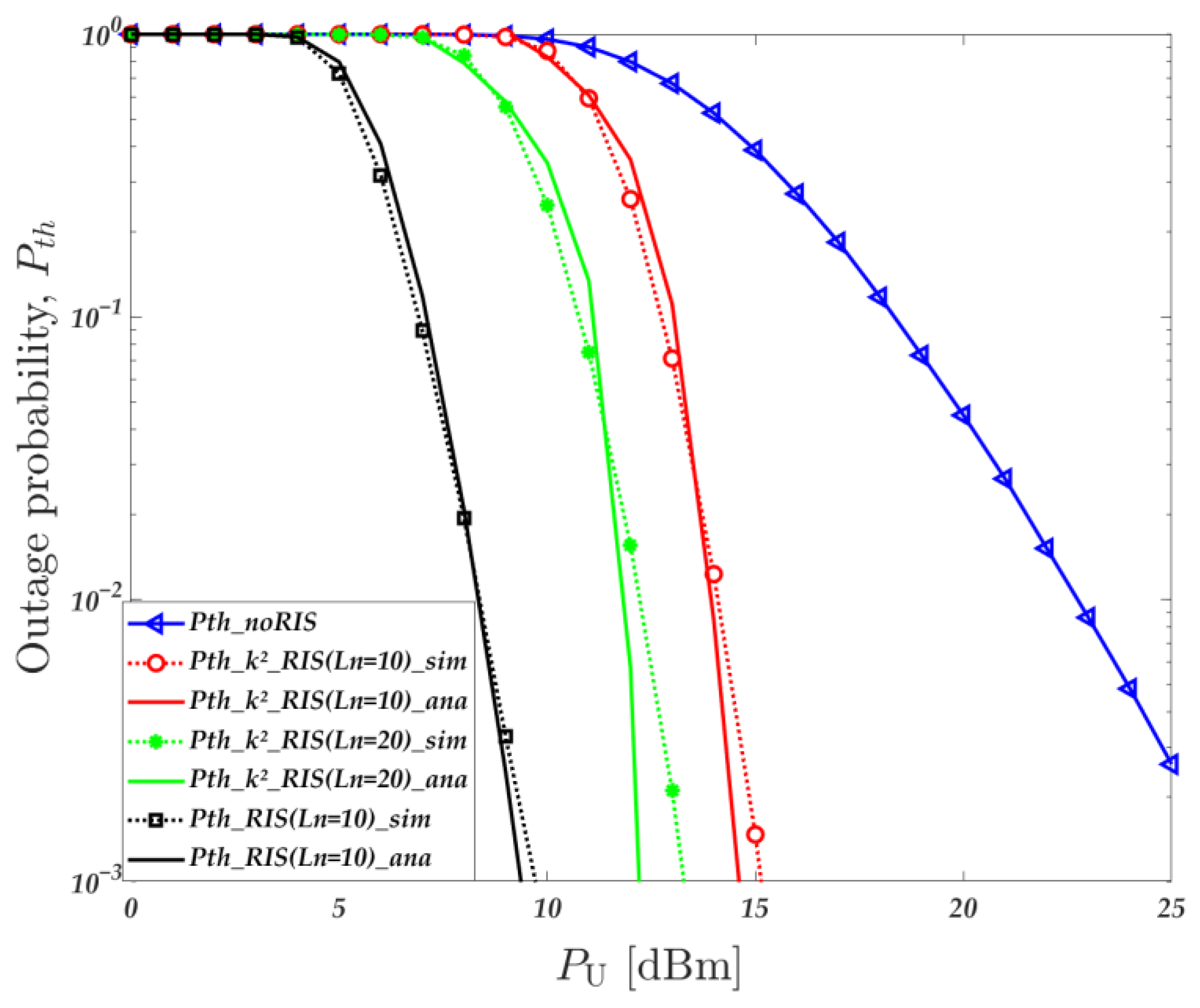
Figure 2 illustrates the relationship between outage probability and transmit power of the UAV across three scenarios: k2_noRIS, k2_RIS, and ideal _RIS. In these scenarios, we consider that each RIS unit Ln = {10, 20}, with a hardware impairment factor of k2 = 0.01. The alignment between the simulation curve and the theoretical approximation curve, as shown in Figure 2, validates the accuracy of our theoretical derivation. Simulation results demonstrate that employing the RIS results in a lower outage probability compared to scenarios without RIS (k2_noRIS), primarily due to the introduction of cascaded links in communication, thus reducing the likelihood of communication outage. Furthermore, the outage probability is impacted by the quantity of RIS units, with a decrease in outage probability correlating with an increase in RIS units. A comparison between the outage probabilities of k2_RIS (Ln = {10, 20}) and ideal_ RIS (Ln = 10) indicates that adding additional RIS units does not fully offset the impact of hardware impairment on outage probability. Notably, hardware impairment heightens the risk of communication outage, underscoring the necessity of accounting for real-world, non-ideal environments in our analysis.
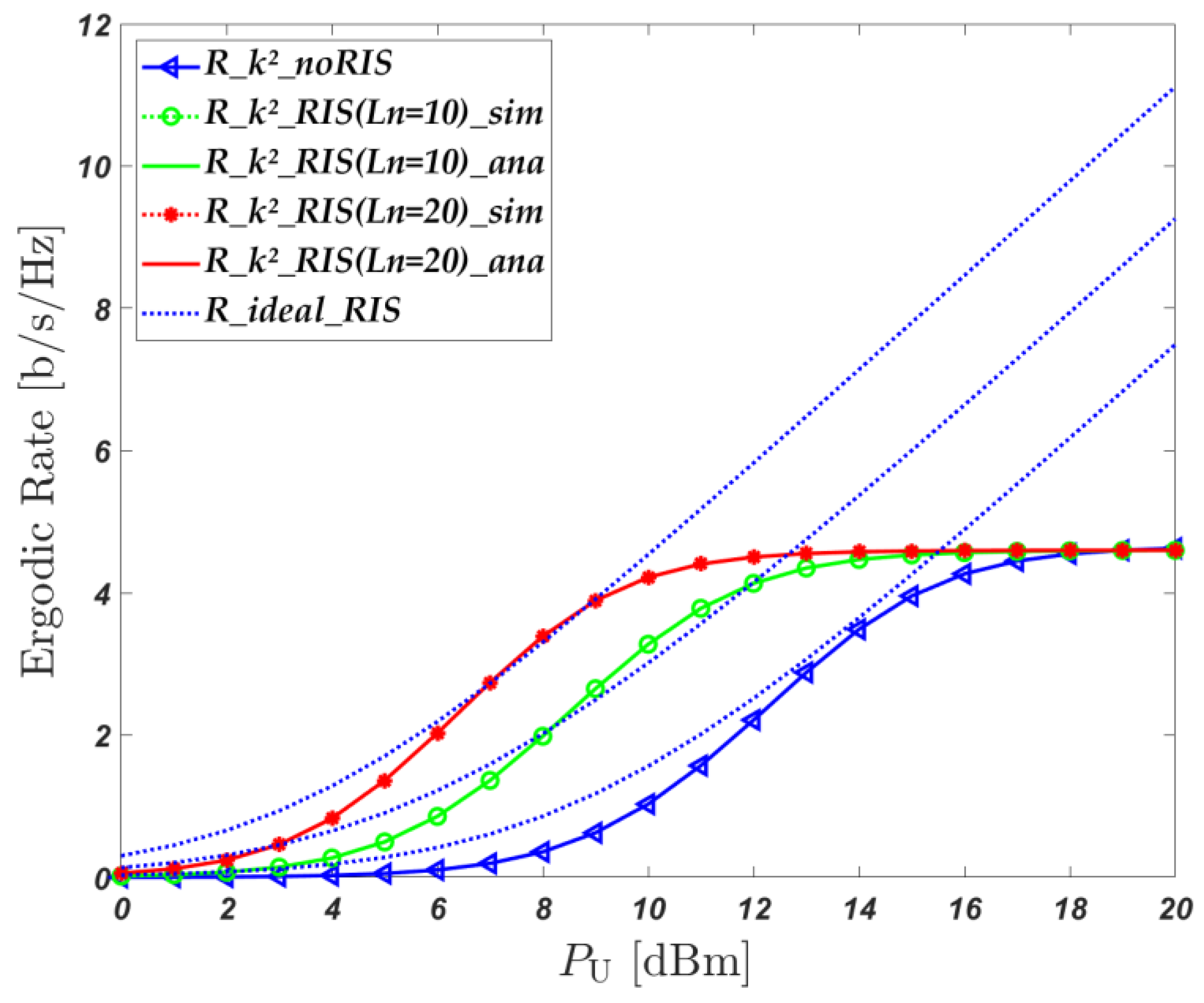
Figure 3 depicts the correlation between the ergodic rate and transmit power of UAV fluctuation in three settings: k2_noRIS, k2_RIS, and ideal _RIS. In these configurations, we consider that each RIS unit Ln = {10, 20}, with a hardware impairment factor of k2 = 0.04. Analysis of Figure 3 reveals that at lower power levels, the ergodic rate of k2_RIS exceeds that of k2_noRIS as the UAV transmit power increases, showcasing the system’s ability to boost the rate with RIS assistance. Simultaneously, the ergodic rate of k2_RIS (Ln = 20) is higher than that of k2_RIS (Ln = 10), which proves that the more RIS units there are, the faster the ergodic rate. However, with the increase in the UAV transmit power, system metrics afflicted by hardware impairment tend to converge, due to hardware damage constraining the upper limit of the ergodic rate. Prior to convergence, under identical circumstances, the curves of k2_RIS and ideal _RIS (Ln = 10) exhibit similarity, suggesting the minimal impact of hardware impairment at lower UAV transmit power levels. Consequently, in practical scenarios with hardware impairment, the UAV base station can effectively operate at lower UAV transmit power levels.
In Figure 4, the correlation between hardware impairment k2, parameter m, and UAV transmit power fluctuation is illustrated, assuming a fixed number of 10 RIS units. The simulation outcomes reveal an inverse relationship between hardware impairment and the ergodic rate’s upper threshold. Specifically, as hardware impairment diminishes, the upper limit of the ergodic rate escalates, a consequence of the impairment’s influence on the rate. Simultaneously, an increase in the parameter m at reduced UAV transmit power levels precipitates a contraction of the ergodic rate. This is primarily due to the fact that when the channel conditions deteriorate, the ergodic rate experiences a significant decrease. Therefore, it can be concluded that the upper limit of the traversal rate is related to hardware damage.
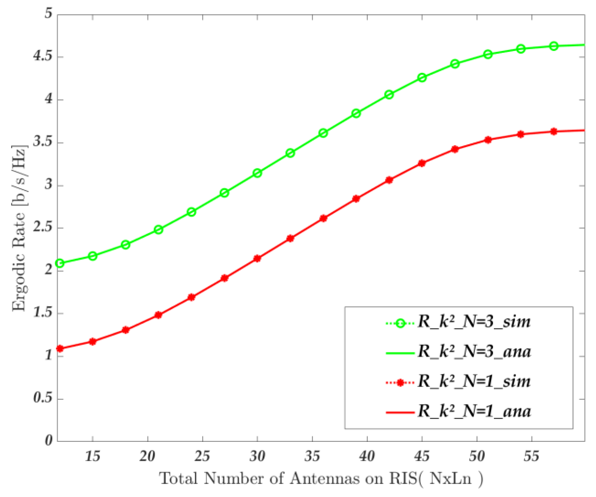
Figure 5 shows the correlation between the ergodic rate and the number of RIS units, considering the presence of hardware impairment. The study compares the ergodic rate of the centralized RIS (N = 1), where all units are centralized into a single RIS, with that of distributed RIS (N = 3). Simulation results demonstrate that the ergodic rate of the distributed RIS outperforms that of the centralized RIS as the number of units increases. These findings emphasize the importance of considering distributed RIS configurations in practical implementations.
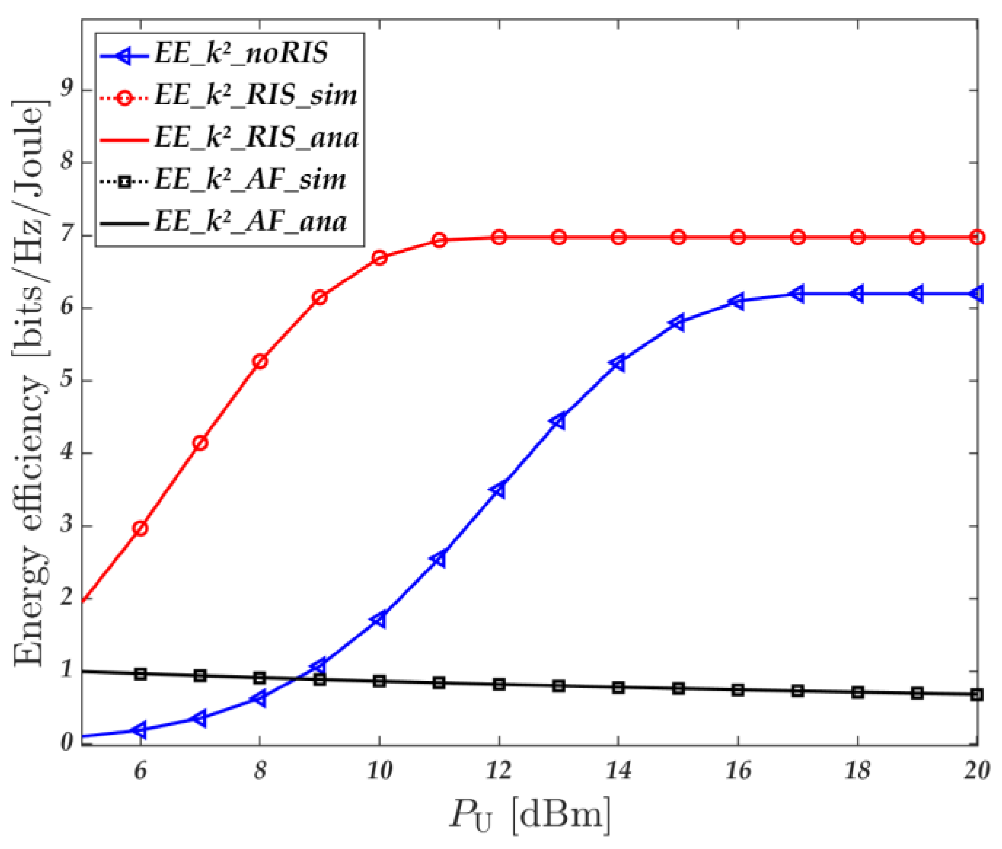
Figure 6 illustrates the correlation between the UAV transmit power variation and energy efficiency in three scenarios: k2_noRIS, k2_RIS, and AF_ k2. The analysis assumes the presence of assuming a fixed number of 10 RIS units and a fixed value of k2 = 0.05. The simulation results clearly indicate that the energy efficiency of k2_RIS surpasses that of k2_noRIS and AF_ k2, attributed to the enhanced transmission rate facilitated by RIS. Furthermore, as k2_noRIS and k2_RIS approach their peaks, a convergence in energy efficiency is observed. This convergence results from the optimization of the UAV transmit power, preventing a decline in energy efficiency. The findings from Figure 6 highlight the potential of distributed RIS-assisted UAV communication in improving energy efficiency, emphasizing the importance of selecting the optimal transmit power level of the UAV to maintain the system energy efficiency.

5. Conclusions

This paper delves into an analysis of the outage probability, ergodic rate, and energy efficiency of distributed RIS-assisted air–ground fusion networks, taking into account non-ideal environmental factors such as hardware impairment, imperfect channels, and random users. Closed-form solutions pertinent to the system performance metrics are derived, utilizing the k2_RIS model as a foundation. An initial comparison between the k2_RIS and k2_noRIS systems demonstrates that RISs can reduce outage probability and enhance the ergodic rate and energy efficiency of air–ground fusion networks. Subsequent comparison with the ideal _RIS system highlights the significant impact of non-ideal factors on the network, emphasizing the necessity of considering these factors. Furthermore, based on the k2_RIS system, differences are distinguished between distributed and centralized RISs. Experimental results indicate that, with a constant number of RIS reflecting units, the energy efficiency of distributed RISs surpasses that of the centralized RIS. A final comparison of the energy efficiency of k2_RIS and AF_ k2 confirms the superior energy efficiency of RIS-assisted networks over AF relay-assisted air–ground fusion networks. Therefore, the proposed distributed RIS-assisted network addresses potential challenges in future wireless communication networks and provides a valuable reference for the practical application of future air–ground fusion networks. In our future research, we will combine a simultaneously transmitting and reflecting reconfigurable intelligent surface (STAR-RIS) and integrated sensing and communication to enhance the overall performance and adaptability of the network, thereby enabling us to delve deeper into the study of RIS-assisted air–ground integrated networks.

Author Contributions

Conceptualization, Y.Y. and Q.L.; methodology, Y.Y. and Q.L.; validation, Y.Y. and Q.L.; formal analysis, Y.Y., Q.L., S.H., K.Y. and X.Y.; investigation, Y.Y. and Q.L; resources, Y.Y.; writing—original draft preparation, Y.Y. and Q.L; writing—review and editing, Y.Y., Q.L., S.H., K.Y. and X.Y.; supervision, Y.Y., S.H., K.Y. and X.Y; project administration, Y.Y.; funding acquisition, Y.Y. All authors have read and agreed to the published version of the manuscript.

Funding

The works of the authors were funded in part by the National Key Research and Development Program of China under Grant 2019YFB1804404, the National Natural Science Foundation of China under Grant No. 62301059, the Project of Cultivation for young top-notch Talents of Beijing Municipal Institutions (BPHR202203228), and the National Natural Science Foundation of China under Grant 62171045.

Data Availability Statement

The data used to support the findings of this study are available from the corresponding author upon request.

Conflicts of Interest

The authors declare no conflicts of interest.

Abbreviations

The following abbreviations are used in this paper:
RISReconfigurable intelligent surface
UAVUnmanned aerial vehicle
5GFifth Generation
6GSixth Generation
HIHardware impairments
BPPBinomial point process
CSIChannel state information

References

  1. Bertin, E.; Crespi, N.; Magedanz, T. Future 6G Networks: Needs, Impacts, and Technologies; John Wiley & Sons Ltd.: Hoboken, NJ, USA, 2021; pp. 12–52. [Google Scholar]
  2. Yu, K.; Yu, J.; Luo, C. The Impact of Mobility on Physical Layer Security of 5G IoT Networks. IEEE/ACM Trans. Netw. 2023, 31, 1042–1055. [Google Scholar] [CrossRef]
  3. Elmossallamy, M.A.; Zhang, H.; Song, L.; Seddik, K.G.; Han, Z.; Li, G. Reconfigurable intelligent surfaces for wireless communications: Principles, challenges, and opportunities. IEEE Trans. Cogn. Commun. Netw. 2020, 6, 990–1002. [Google Scholar] [CrossRef]
  4. Renzo, M.D.; Zappone, A.; Debbah, M.; Alouini, M.; Yuen, C.; Rosny, J.D.; Tretyakov, S.A. Smart radio environments empowered by reconfigurable intelligent surfaces: How it works, state of research, and the roadahead. IEEE J. Sel. Areas Commun. 2020, 38, 2450–2525. [Google Scholar] [CrossRef]
  5. Başar, E.; Di Renzo, M.; de Rosny, J.; Debbah, M.; Alouini, M.; Zhang, R. Wireless communications through reconfigurable intelligent surfaces. IEEE Access 2019, 7, 116753–116773. [Google Scholar] [CrossRef]
  6. Zhang, S.; Zhang, R. Capacity Characterization for Intelligent Reflecting Surface Aided MIMO Communication. IEEE J. Sel. Areas Commun. 2020, 38, 1823–1838. [Google Scholar] [CrossRef]
  7. Yang, Y.; Zheng, B.; Zhang, S.; Zhang, R. Intelligent Reflecting Surface Meets OFDM: Protocol Design and Rate Maximization. IEEE Trans. Commun. 2020, 68, 4522–4535. [Google Scholar] [CrossRef]
  8. Yue, X.; Xie, J.; Ouyang, C.; Liu, Y.; Shen, X.; Ding, Z. Active Simultaneously Transmitting and Reflecting Surface Assisted NOMA Networks. arXiv 2024, arXiv:2401.14219. [Google Scholar]
  9. Yue, X.; Song, M.; Ouyang, C.; Liu, Y.; Li, T.; Hou, T. Exploiting Active RIS in NOMA Networks with Hardware Impairments. arXiv 2024, arXiv:2311.14295. [Google Scholar]
  10. Liu, X.; Xu, X.; Yu, K. NOMA and UAV Scheduling for Ultra-Reliable and Low-Latency Communications. Drones 2023, 7, 41. [Google Scholar] [CrossRef]
  11. Mei, W.; Zhang, R. Cooperative beam routing for multi-IRS aided communication. IEEE Wireless Commun. Lett. 2021, 10, 426–430. [Google Scholar] [CrossRef]
  12. Di Renzo, M.; Ntontin, K.; Song, J.; Danufane, F.H.; Qian, X.; Lazarakis, F.I.; de Rosny, J.; Phan-Huy, D.; Simeone, O.; Zhang, R.; et al. Reconfigurable Intelligent Surfaces vs. Relaying: Differences, Similarities, and Performance Comparison. IEEE Open J. Commun. Soc. 2019, 1, 798–807. [Google Scholar] [CrossRef]
  13. Gao, Y.; Xu, J.; Xu, W.; Ng, D.W.; Alouini, M. Distributed IRS with statistical passive beamforming for MISO communications. IEEE Wirel. Commun. Lett. 2021, 10, 221–225. [Google Scholar] [CrossRef]
  14. Do, T.; Kaddoum, G.; Nguyen, T.; Costa, D.B.; Haas, Z.J. Multi-RIS-aided wireless systems: Statistical characterization and performance analysis. IEEE Trans. Commun. 2021, 69, 8641–8658. [Google Scholar] [CrossRef]
  15. Yao, Y.; Lv, K.; Ma, N.; Yue, X.; Qin, X.; Yun, X. Energy efficient air-to-ground communication networks with reconfigurable intelligent surface. J. Commun. Netw. 2022, 24, 555–565. [Google Scholar] [CrossRef]
  16. Yao, Y.; Lv, K.; Huang, S.; Li, X.; Xiang, W. UAV Trajectory and Energy Efficiency Optimization in RIS-Assisted Multi-User Air-to-Ground Communications Networks. Drones 2023, 7, 272. [Google Scholar] [CrossRef]
  17. Shang, B.; Shafin, R.S.; Liu, L. UAV Swarm-Enabled Aerial Reconfigurable Intelligent Surface (SARIS). IEEE Wirel. Commun. 2021, 28, 156–163. [Google Scholar] [CrossRef]
  18. Li, Y.; Aghvami, A.H.; Dong, D. Path Planning for Cellular-Connected UAV: A DRL Solution with Quantum-Inspired Experience Replay. IEEE Trans. Wirel. Commun. 2022, 21, 7897–7912. [Google Scholar] [CrossRef]
  19. Li, Y.; Aghvami, A.H. Radio Resource Management for Cellular-Connected UAV: A Learning Approach. IEEE Trans. Commun. 2023, 71, 2784–2800. [Google Scholar] [CrossRef]
  20. Shang, B.; Liu, L.; Ma, J.; Fan, P.; Unmanned Shang, B.; Shafin, R.S.; Liu, L. Unmanned aerial vehicle meets vehicle-to-everything in secure communications. IEEE Commun. Mag. 2019, 57, 98–103. [Google Scholar] [CrossRef]
  21. Hua, M.; Yang, L.; Wu, Q.; Swindlehurst, A.L. 3D UAV trajectory and communication design for simultaneous uplink and downlink transmission. IEEE Trans. Commun. 2020, 68, 5908–5923. [Google Scholar] [CrossRef]
  22. Li, S.; Duo, B.; Yuan, X.; Liang, Y.; Di Renzo, M. Reconfigurable intelligent surface assisted UAV communication: Joint trajectory design and passive beamforming. IEEE Wirel. Commun. Lett. 2020, 9, 716–720. [Google Scholar] [CrossRef]
  23. Guo, J.; Yu, L.; Chen, Z.; Yao, Y.; Wang, Z.; Wang, Z.; Zhao, Q. RIS-assisted secure UAV communications with resource allocation and cooperative jamming. IET Commun. 2022, 16, 1582–1592. [Google Scholar] [CrossRef]
  24. Tran, P.T.; Nguyen, B.C.; Hoang, T.M.; Le, X.H.; Nguyen, V.D. Exploiting Multiple RISs and Direct Link for Performance Enhancement of Wireless Systems with Hardware Impairments. IEEE Trans. Commun. 2022, 70, 5599–5611. [Google Scholar] [CrossRef]
  25. Nguyen, B.C.; The Dung, L.; Hoang, T.M.; Tran, X.N.; Kim, T. Impacts of imperfect CSI and transceiver hardware noise on the performance of full-duplex DF relay system with multi-antenna terminals over Nakagami-m fading channels. IEEE Trans. Commun. 2021, 69, 7094–7107. [Google Scholar] [CrossRef]
  26. Papasotiriou, E.N.; Boulogeorgos, A.-A.-A.; Alexiou, A. Performance analysis of THz wireless systems in the presence of antenna misalignment and phase noise. IEEE Commun. Lett. 2020, 24, 1211–1215. [Google Scholar] [CrossRef]
  27. Papazafeiropoulos, A.K.; Sharma, S.K.; Ratnarajah, T.; Chatzinotas, S. Impact of residual additive transceiver hardware impairments on Rayleigh-product MIMO channels with linear receivers: Exact and asymptotic analyses. IEEE Trans. Commun. 2018, 66, 105–118. [Google Scholar] [CrossRef]
  28. Hou, T.; Liu, Y.; Song, Z.; Sun, X.; Chen, Y.; Hanzo, L.H. MIMO Assisted Networks Relying on Intelligent Reflective Surfaces: A Stochastic Geometry Based Analysis. IEEE Trans. Veh. Technol. 2022, 71, 571–582. [Google Scholar] [CrossRef]
  29. Haenggi, M. Stochastic Geometry for Wireless Networks; Cambridge University Press: Cambridge, UK, 2012. [Google Scholar]
  30. Andrews, J.G.; Baccelli, F.; Ganti, R.K. A tractable approach to coverage and rate in cellular networks. IEEE Trans. Commun. 2011, 59, 3122–3134. [Google Scholar] [CrossRef]
  31. Kishk, M.A.; Alouini, M. Exploiting randomly located blockages for large-scale deployment of intelligent surfaces. IEEE J. Sel. Areas Commun. 2021, 39, 1043–1056. [Google Scholar] [CrossRef]
  32. Singh, S.K.; Agrawal, K.; Singh, K.; Li, C.; Ding, Z. NOMA Enhanced Hybrid RIS-UAV-Assisted Full-Duplex Communication System with Imperfect SIC and CSI. IEEE Trans. Commun. 2022, 70, 7609–7627. [Google Scholar] [CrossRef]
  33. Fontán, F.P.; Espiñeira, P.M. Modelling the Wireless Propagation Channel: A Simulation Approach with MATLAB; Wiley Publishing: Hoboken, NJ, USA, 2008. [Google Scholar]
  34. Ntontin, K.; Song, J.; Renzo, M.D. Multi-antenna relaying and reconfigurable intelligent surfaces: End-to-end SNR and achievable rate. arXiv 2019, arXiv:1908.07967. [Google Scholar]
  35. Liu, H.; Yuan, X.; Jun, Y. Matrix-calibration-based cascaded channel estimation for reconfigurable intelligent surface assisted multiuser MIMO. IEEE J. Sel. Areas Commun. 2020, 11, 2621–2636. [Google Scholar] [CrossRef]
  36. Jeffrey, A.; Zwillinger, D. Table of Integrals, Series, and Products; Academic: New York, NY, USA, 2007. [Google Scholar]
  37. Goldsmith, A. Wireless Communications; Cambridge University Press: Cambridge, UK, 2005. [Google Scholar]
  38. Peebles, P.Z. Random Variables and Random Signal Principles, 4th ed.; McGraw-Hill: New York, NY, USA, 2000. [Google Scholar]
  39. Zan, J.; Lu, G.; Ye, Y. Outage performance of UAV-assisted AF relaying with hardware impairments. Phys. Commun. 2021, 46, 101334. [Google Scholar] [CrossRef]
Figure 1. Distributed RIS assisted air–ground fusion network system based on non-ideal environment.
Drones 08 00271 g001
Figure 2. The relationship between outage probability and the UAV transmit power variation, where N = 3, Ln = {10, 20}, and k2 = 0.01.
Drones 08 00271 g002
Figure 3. The relationship between ergodic rate and UAV transmit power variation, where N = 3, Ln = {10, 20}, and k2 = 0.04.
Drones 08 00271 g003
Figure 4. The relationship between hardware impairment and channel parameter variations, N = 3, and Ln= 10.
Drones 08 00271 g004
Figure 5. The relationship between the ergodic rate and the number of RIS reflecting elements, k2 = 0.01, and PU = 9 dBm.
Drones 08 00271 g005
Figure 6. The relationship between energy efficiency and the UAV transmit power variation, k2 = 0.05, P1 = 10 dBm, and PRIS = 1 dBm.
Drones 08 00271 g006
Table 1. Main Notation.
NotationDefinition
NNumber of RISs
LnNumber of RIS reflecting elements
h0, hn, gnThe channel gains for the UAV-USER, UAV-RIS, RIS-USER
d1, d2,n, d3,nThe distance for UAV-USER, UAV-RIS, RIS-USER
ΛPath loss exponent
N0Gaussian white noise
Ne1Noise caused by imperfect channels in UAV-USER links
Ne2Noise caused by imperfect channels in UAV-RIS links
k2HI level
r0, RThe inner and outer parameters of the annulus
mThe shape parameter indicating the severity of fading
ΩThe extended parameter of the distribution
Table 2. Simulation parameters.
Simulation ParametersValue
Path loss exponent3
The number of RISsN = 3
The power consumption of the userP1 = 10 dBm
The power consumption of RIS elementPRIS = 1 dBm
The radius of discR = 10 m r0 = 1 m
Bandwidth 100 MHz
Disclaimer/Publisher’s Note: The statements, opinions and data contained in all publications are solely those of the individual author(s) and contributor(s) and not of MDPI and/or the editor(s). MDPI and/or the editor(s) disclaim responsibility for any injury to people or property resulting from any ideas, methods, instructions or products referred to in the content.