Review

Runway-Free Recovery Methods for Fixed-Wing UAVs: A Comprehensive Review

Department of Aeronautics and Astronautics, Fudan University, Shanghai 200433, China
*
Author to whom correspondence should be addressed.
These authors contributed equally to this work.
Drones 2024, 8(9), 463; https://doi.org/10.3390/drones8090463
Submission received: 27 July 2024 / Revised: 21 August 2024 / Accepted: 4 September 2024 / Published: 5 September 2024

Abstract

:
Fixed-wing unmanned aerial vehicles (UAVs) have the advantages of long endurance and fast flight speed and are widely used in surveying, mapping, monitoring, and defense fields. However, its conventional take-off and landing methods require runway support. Achieving runway-free recovery is necessary for expanding the application of fixed-wing UAVs. This research comprehensively reviews the various techniques and scenarios of runway-free recovery of fixed-wing UAVs and summarizes the key technologies. The above methods cover parachute recovery, net recovery, rope recovery, SideArm recovery, deep stall recovery, towed drogue docking recovery, and robotic arm recovery methods within runway-free recovery. Finally, this research discusses the future research directions of runway-free recovery.

1. Introduction

With the rapid development of aviation technology, UAVs have been used more and more widely, playing an important role in many fields, such as agricultural monitoring [1], remote sensing [2], urban security [3], and meteorological detection [4]. At present, common UAVs can be divided into three categories according to their aerodynamic configuration: fixed-wing UAVs [5], copter UAVs [6], and vertical take-off and landing (VTOL) fixed-wing UAVs [7]. The three types of UAVs are widely used in differentiated application scenarios due to their different functional advantages. However, the three types of UAVs also have their shortcomings. Fixed-wing UAVs have the advantages of long cruising time, high cruising speed, and large payload. They have long occupied an important position in meteorological detection [8,9], agricultural monitoring [10,11], remote sensing [12,13], and national defense [14,15]. However, fixed-wing UAVs have higher requirements for sites or launch and recovery systems during take-off and landing. In essence, VTOL UAVs are an evolution made to improve the take-off and landing performance and site requirements of fixed-wing UAVs. However, the vertical take-off and landing power system also brings additional weight increases, affecting the carrying weight of the payload. Copter UAVs can take off and land vertically and have lower environmental requirements. However, their flight time is usually short and cannot meet the needs of various applications in all weather conditions. Therefore, many studies have been conducted on the innovation of take-off and landing methods and the efficiency improvement of conventional fixed-wing UAVs.
Standard take-off methods for fixed-wing UAVs include runway take-off [16] and catapult take-off [17], and their recovery method is usually runway landing [18]. For fixed-wing UAVs, the strict environmental requirements and space required for runway take-off and landing have restricted their more comprehensive application to a certain extent. Conventional fixed-wing UAV runway recovery methods cannot be applied to environments that do not have runways for take-off and landing on ships, aircraft, or land. Runway-free recovery can save the space required for fixed-wing UAV recovery. Additionally, runway recovery efforts must fully consider the issue of runway occupancy. Runway-free recovery can offer significant improvements in saving construction costs and improving utilization efficiency. Effectively addressing the critical issues in the runway-free recovery process can enhance the mission effectiveness of fixed-wing UAVs in various scenarios, thus promoting their further application and expansion. It is urgent to carry out innovative recovery system design and scientific research for fixed-wing UAVs. Figure 1 shows the typical forms of runway landing and runway-free recovery of fixed-wing UAVs.
This paper aims to review the runway-free recovery methods and application scenarios of fixed-wing UAVs. To this end, previous research and related UAV recovery products are explored, and their application scenarios are reviewed. Critical technologies in the automated recovery process and commonly used guidance sensors have also been introduced. The technical challenges faced by runway-free recovery and future research directions are discussed.
The rest of the paper is organized as follows. Section 2 summarizes the search method that has been followed throughout the survey. Section 3 classifies different approaches to runway-free recovery of fixed-wing UAVs, including parachute recovery, net recovery, rope capture recovery, SideArm recovery, deep stall recovery, towed drogue docking recovery, and robotic arm recovery. Section 4 presents and classifies path planning and guidance technology for runway-free recovery of fixed-wing UAVs: linear planning, line of sight (LOS) guidance, multi-objective optimization methods, machine learning methods, and heuristic algorithms. Section 5 discusses position and attitude control methods during recovery in four categories: classical control algorithms, modern control algorithms, intelligent control algorithms, and predictive control algorithms. Section 6 classifies relative position sensors of recovery, including GNSS, visible light camera, infrared (IR) camera, and depth camera. Section 7 offers the discussion and future research directions; it summarizes the results and discusses the future research directions. Section 8 concludes the survey.

2. Search Method

This study is focused on the methods and technologies for runway-free recovery of fixed-wing UAVs. We used Google Scholar, IEEE Xplore, Engineering Village, and Science Direct to conduct our search. We looked for publications from 2001 to July 2024. The search method used to identify related articles and previous reviews on “runway-free recovery of fixed-wing UAVs” is detailed in Table 1. We included published research papers with experimental demonstrations, experiments with simulations, and numerical results, and we categorized them accordingly. All the included papers have been reviewed for originality, technical quality, and relevance to the mentioned challenges.

3. Fixed-Wing UAVs Runway-Free Recovery Methods and Applications

This paper comprehensively reviews the research on runway-free recovery of fixed-wing UAVs and divides them into seven categories based on the device structures and dynamic characteristics of the recovery methods: (1) parachute recovery; (2) net recovery; (3) rope capture recovery; (4) SideArm recovery; (5) deep stall recovery; (6) towed drogue docking recovery; (7) robotic arm recovery.

3.1. Parachute Recovery

Parachute recovery [21] uses the resistance of the open parachute to quickly decelerate the UAV so that the UAV can land safely. The application range of parachute recovery is extensive. The parachute can deploy at various speeds and altitudes. The recyclables can be safely and effectively slowed down and landed on the ground or water surface. The parachute can deploy at various speeds and altitudes. The recyclables can be safely and effectively slowed down and landed on the ground or water surface. The force on the UAV will be increased due to impact, so the UAV structure must have a certain strength and rigidity to open the parachute and land safely. If needed, the fuselage of the UAV will be reinforced. Due to its advantages of simple layout, low cost, and full automation, parachute recovery is currently one of the most commonly used methods for runway-free recovery of civil fixed-wing UAVs [22], and parachute recovery can be utilized on various UAV configurations, including those with front and rear engines.
The process of parachute recovery is usually divided into three stages: unpowered fall, parachute ejection and inflation, and free falling of the UAV [23]. When the UAV reaches a suitable height and speed, the parachute is actively released, and after being straightened and actively inflated, the parachute pulls the UAV to land stably [24]. The geometric characteristics of the parachute determine its aerodynamic characteristics and stability, which in turn affect the resistance at the moment of parachute opening and during landing, as well as the motion trajectory of the UAV [25].
Figure 2 shows the complete process of a UAV from cruising to parachute landing and the main components of a parachute. The parachute canopies can be classed as cross-type canopies, round canopies, and parafoils. According to the opening method, parachute landing can be divided into natural inflation opening, actuator opening, and tractor rocket ejection opening, which are introduced below.

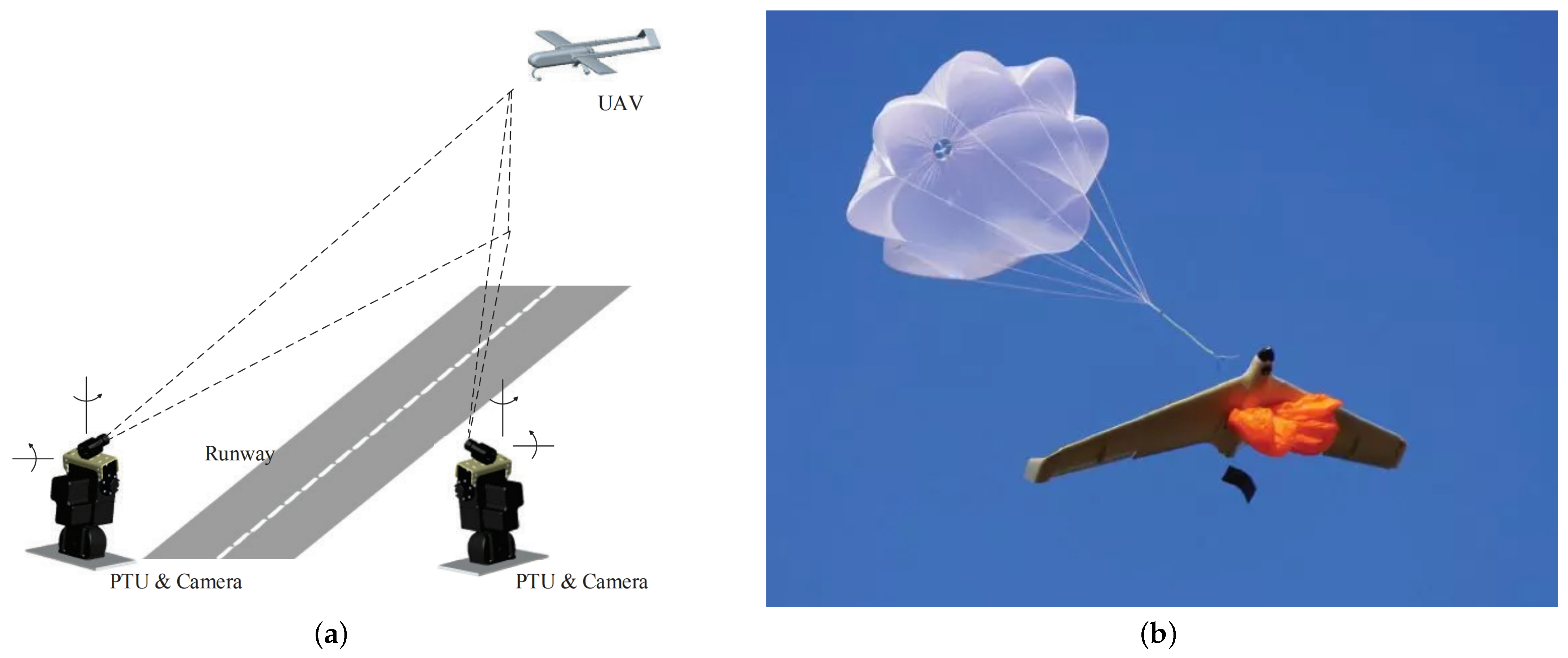
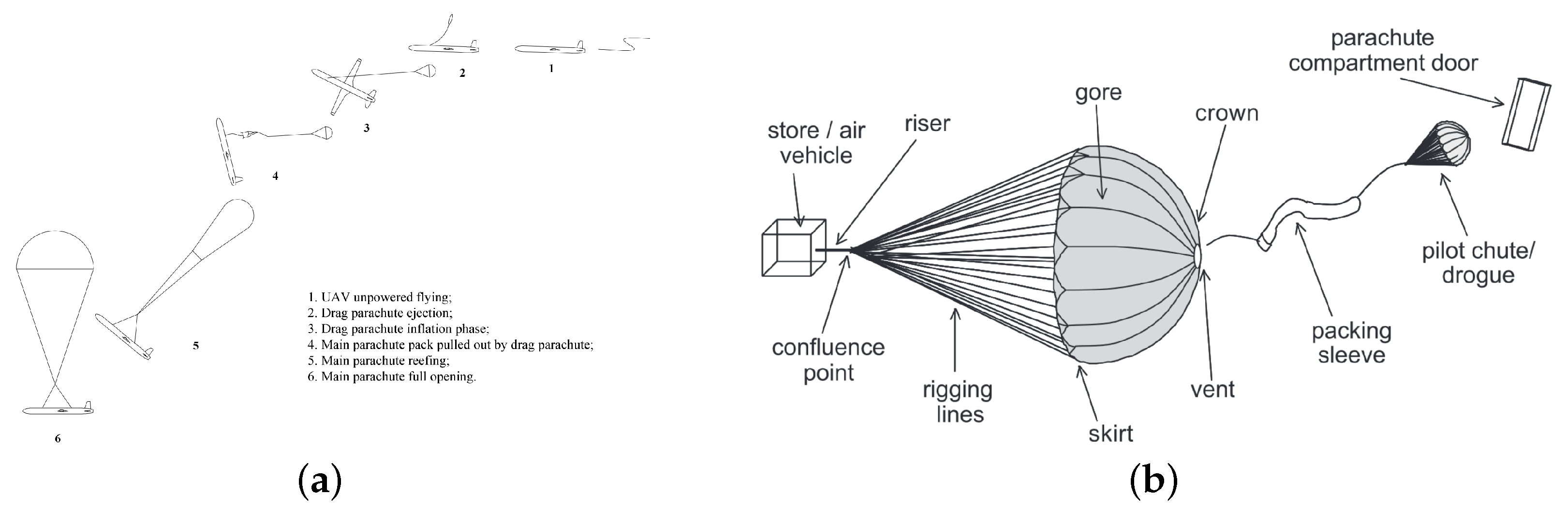
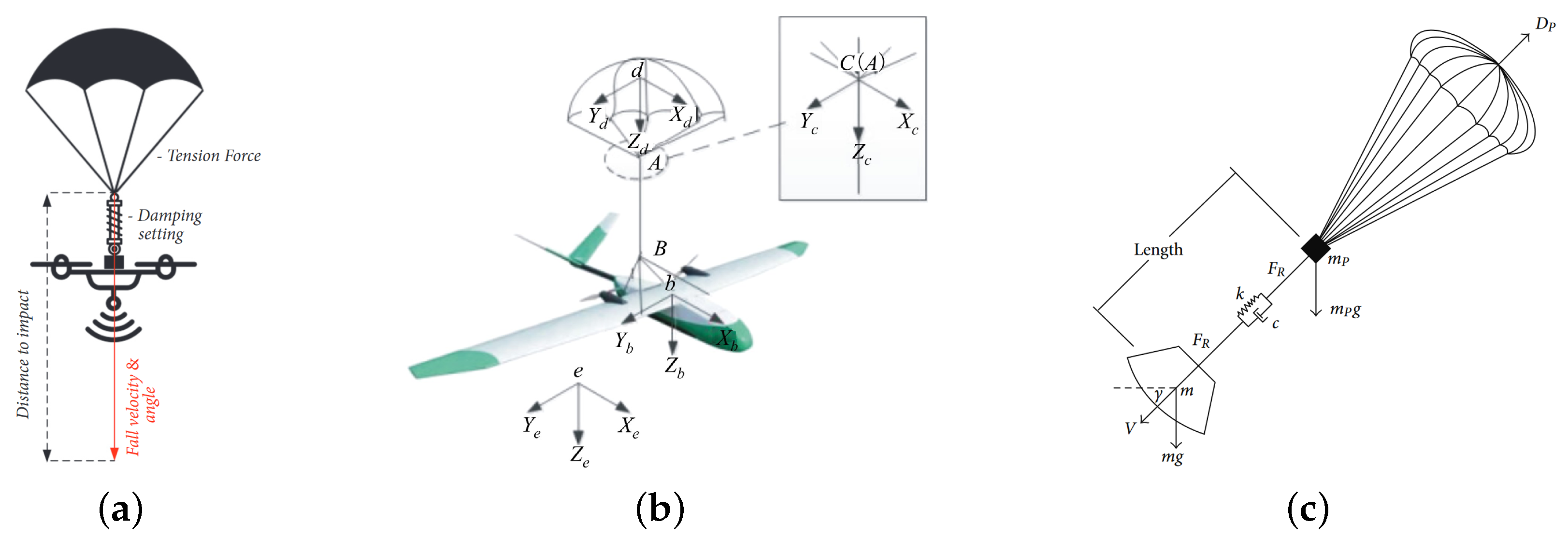
3.1.1. Natural Inflation Opening

The natural inflation opening method uses air resistance inside the parachute skirt to inflate the parachute. The device is simple and low-cost, suitable for small fixed-wing UAVS and recovery in a safe environment [28]. This method has been widely applied in low-cost recovery scenarios such as mountainous surveying, agricultural spraying, and disaster relief with insufficient landing space.
During the active inflation phase of the parachute, the center of gravity of the UAV parachute combination and the angle of attack of the UAV change greatly and are easily affected by environmental factors, which poses significant challenges to the aerodynamic modelling of the UAV parachute combination structure during the inflation phase, the calculation of the UAV landing point, and the timing of the parachute opening. Wu et al. [29] used the principle of virtual work and the Lagrange equation to establish six degrees of freedom (6-DOF) UAV and parachute dynamic models, respectively, and accurately simulated the changes in the angle of attack and forward velocity of a 10 kg UAV during parachute recovery, which was successfully tested on a 2 kg UAV with a fall velocity of 5 m/s. As shown in Figure 3a, AL-Madani et al. [26] designed an acceleration sensor based on temperature compensation for automatic parachute opening during a UAV failure.
On the other hand, the shape and structure of the parachute affect the stability of the UAV’s landing and the deceleration effect of the UAV during the inflation phase. By analyzing three real-world scenarios, Wyllie et al. [27] compared the relative advantages and disadvantages of cross-type canopies, round canopies, and parafoils. As shown in Figure 3c, Guglieri et al. [25] modelled the elastic parachute rope and flow field behavior of the parachute during the inflation phase to better estimate the overloads on the UAV.

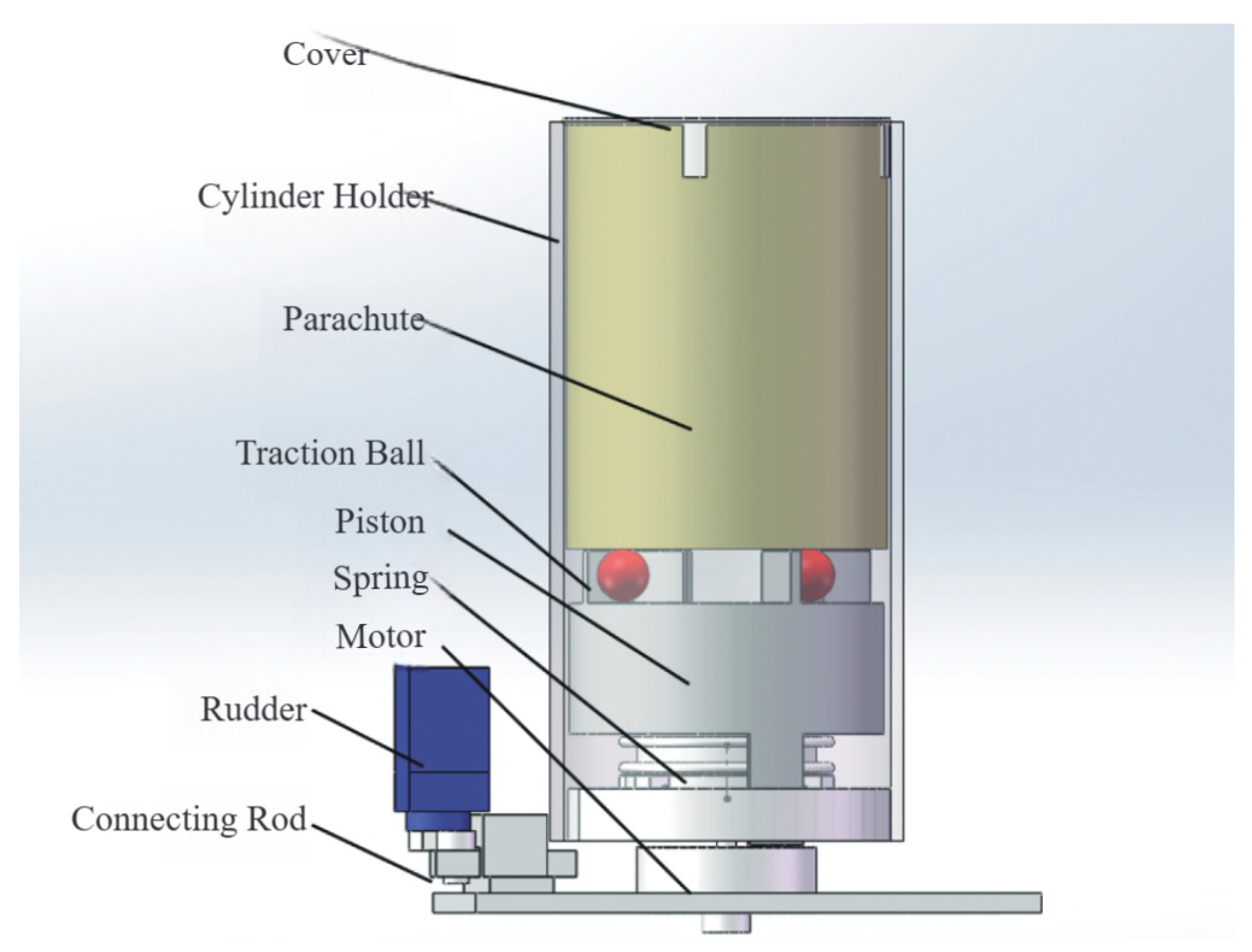
3.1.2. Actuator Opening

The speed of naturally inflating a parachute is slow, and the effect is unstable. As a result, a mechanical structure has been designed to open the parachute by towing it. By rotating the traction ball installed in multiple directions to pop it out, the effective wind area of the parachute increases quickly after the pop-up, thereby accelerating the inflation speed of the parachute. Common ejection methods include spring ejection and compressed gas ejection.
Pan et al. [31] conducted a dynamic simulation of the flow field during the parachute inflation phase and obtained the variation curve of the drag coefficient during the primary inflation process. Yang et al. [23] designed a spring ejection device and obtained the optimal motor speed and spring elastic coefficient through simulation.
Figure 4 is a schematic diagram of a spring ejection device. The motor drives the device to rotate as a whole. When a certain speed is reached, the rudder unlocks the spring through the connecting rod and the piston. The spring ejects the parachute out of the cover, and then the traction ball pulls the parachute open, thereby achieving rapid parachute opening.

3.1.3. Tractor Rocket Ejection Opening

In recent years, with the rapid development of emerging technologies, the application scenarios and deployment environments of UAVs have become increasingly complex. The inflation and deployment process of traditional natural inflation opening and actuator opening is slow, and the safety of parachute recovery of UAVs in complex environments and emergencies is insufficient [32]. Therefore, a technology using a tractor rocket to eject the parachute [33] has gradually emerged to quickly eject and inflate parachutes in emergencies.
Li et al. [34] simulated the dynamics of a rocket forced parachute drawing in windless conditions and reduced the vertical speed from 30 m/s to 6 m/s in a descent height of 70 m, verifying the effectiveness of tractor rocket ejection technology in emergencies. As shown in Figure 5a, Shi et al. [32] designed a rocket device and successfully deployed a parachute in 0.93 s in a real experiment using a 250 kg UAV with an H-type double-tail-support layout. Shi [33] used simulation software to simulate the deployment process of parachutes with round and cross-shaped canopies during rocket parachute deployment, and the error compared with the experimental data at normal temperature was 20.87%.
The parachute recovery method is a more researched and mature UAV recovery method. It is suitable for low-cost, reusable fixed-wing UAV recovery in a safe environment with low landing accuracy requirements. However, due to the slow opening speed of the parachute and the more significant impact on the environment, the success rate of parachute recovery in complex environments and emergencies is difficult to guarantee. Although the tractor rocket ejection opening method can complete the opening and inflation of the parachute quickly, it also requires sufficient height for the parachute to decelerate, increasing the cost and difficulty of installation and maintenance. It is more suitable for emergency solutions rather than general recovery methods.

3.2. Net Recovery

Net recovery is a method of recovering fixed-wing UAVs based on a flexible net. The device used in this method is relatively simple and usually only requires a V-shaped base, a recovery net, and an energy-absorbing swing arm to form a UAV recovery device. After the UAV is guided and hits the net surface at a low speed, the wings of the UAV will be caught by the net rope. The energy-absorbing swing arm will absorb the forward kinetic energy of the UAV, and the UAV will eventually be recovered [35,36]. Currently, net recovery is widely used in land-based and shipborne UAV recovery.
There are also studies on fixed-wing UAV recovery tests based on the collaborative pulling of a net by two multicopter UAVs [37,38]. This type of research requires high coordination between multicopter UAVs, and the state of the net is easily affected by wind and turbulence. These factors may impact the reliability of recovery, and its practical application still has technical problems that must be overcome.
Figure 6 shows the application cases of net recovery in several typical scenarios. Early fixed-net recovery has matured in application, and new research is currently focusing on automatic recovery based on mobile platforms. Figure 7 shows a planning strategy for net recovery on mobile platforms. The recovery process is defined through six stages: pre-recovery, transit, alignment, approach, final alignment, and catch. The automatic recovery test is implemented through the proposed automatic control architecture and method [39].
Net recovery has the advantages of a simple device structure and a high automatic docking success rate, and the weight range of recoverable UAVs is relatively large. However, it also has significant defects. During recovery, the propellers, wings, antennas, and other external components of the UAVs are easily entangled by the net rope, and the UAV removal process is time-consuming and cannot be automated. At the same time, net recovery also has requirements for the layout of fixed-wing UAVs, which need to be a rear-propeller layout as much as possible. Suppose it is a UAV with a front-mounted propeller layout. In that case, it needs to consider how to make the propeller stop early when it contacts the net during recovery to reduce potential damage to the net.

3.3. Rope Recovery

Rope recovery usually refers to the precise recovery of fixed-wing UAVs with the help of ropes. According to the distribution direction of the rope, it can be generally divided into horizontal rope recovery and vertical rope recovery. Vertical rope recovery is also called SkyHook recovery. Rope recovery is usually performed at the average approach speed of the fixed-wing UAV. The fixed-wing UAV is decelerated and recovered after being blocked by the rope. The following is a detailed discussion of the two forms of rope recovery. Figure 8 shows a comparison of the two rope recovery methods.

3.3.1. Horizontal Rope Recovery

Horizontal rope recovery usually refers to the state where the capture rope is horizontal to the ground during recovery. The recovery device usually consists of a capture rope and a fixed seat. The bottom of the recovered UAV usually has a retractable recovery hook [44]. The horizontal rope recovery process can usually be divided into four steps: (1) approach, (2) pre-recovery, (3) capture, and (4) stow, which are defined as follows.
  • Approach: The UAV is guided to the rear area of the capture rope, and the altitude and heading of the UAV are adjusted to align with the capture rope;
  • Pre-recovery: The UAV tracks or aligns with the capture at a preset speed, and the recovery hook on the UAV is lowered, ready to enter the capture phase;
  • Capture: If the capture rope successfully intercepts the UAV, the capture is successful. If not, the UAV enters a roundabout route;
  • Stow: If the UAV is successfully captured, the UAV can be taken down manually or by a robotic arm and recovered to a designated location, thus completing the entire recovery process.
The above process is shown in Figure 9.
Figure 10 shows several typical application scenarios for horizontal rope recovery, which can be flexibly deployed on land or ships.
In addition to the conventional capture rope method using a fixed seat, studies are exploring using two multicopter UAVs to pull the capture rope to form a UAV recovery device [48]. This study successfully recovered a UAV weighing 1.4 kg, making the horizontal rope recovery method more suitable for UAV recovery in space-constrained areas such as small ships.
Horizontal rope recovery has the advantages of a straightforward recovery device structure, convenient deployment, and small vertical space. However, this method requires high guidance accuracy of the UAV, and the design of the arresting recovery hook and structural strength verification of the UAV needs to be considered during the design process. For UAVs using horizontal rope recovery, the damage that the propeller may cause to the rope should be considered. Therefore, the release form of the arresting hook mounted on the UAV must be considered and designed to avoid the propeller’s impact on the rope.

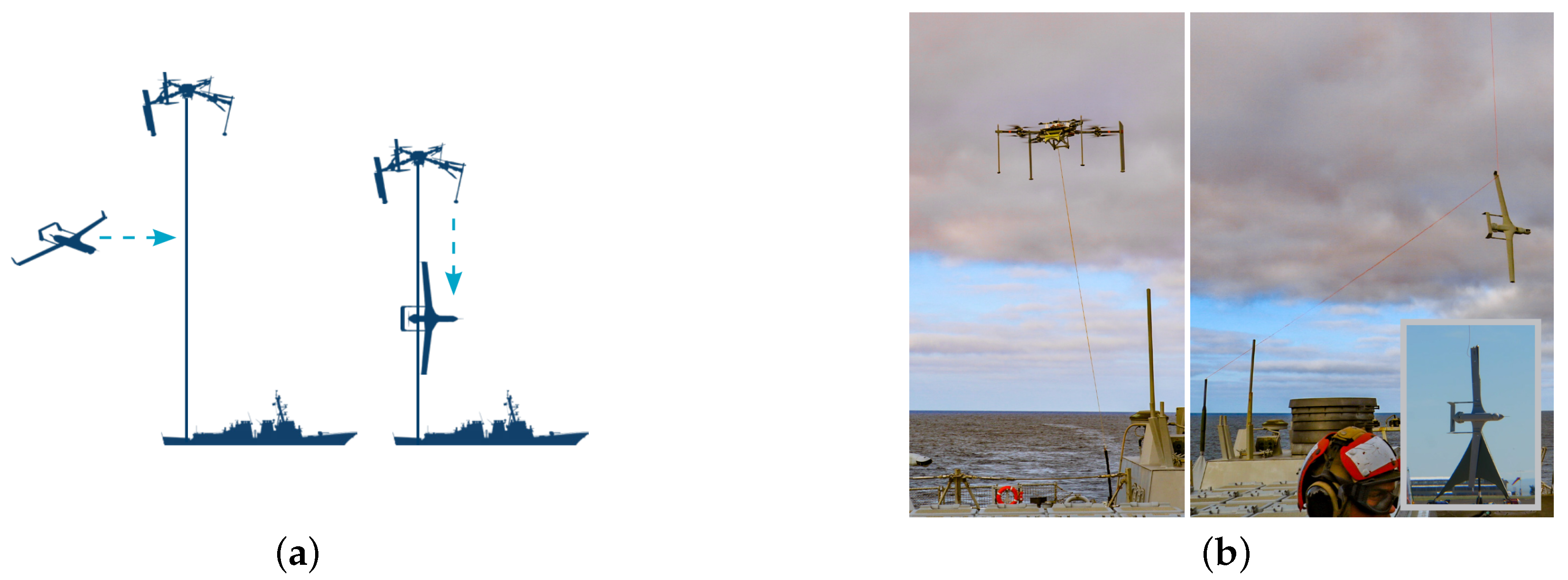
3.3.2. Vertical Rope Recovery

Analysis of the vertical rope recovery system shows that it mainly comprises a recovery bracket, a vertical rope device, and a wingtip arresting hook on a fixed-wing UAV. This differs from horizontal rope recovery, in which the capture rope is usually perpendicular to the ground during recovery. This recovery system can usually be deployed on land [49] and ships [50] and can achieve fixed-point recovery of fixed-wing UAVs based on the capture rope capturing the UAV’s wingtip arresting hook. Vertical rope recovery is also called SkyHook recovery, and, usually, during the recovery process, the UAV is guided to the vicinity of the recovery device by a guidance device. When the wing of the UAV hits the vertical hole and is arrested by it, the vertical rope then slides along the leading edge of the UAV’s wing to the wingtip arresting hook. After the wingtip arresting hook hooks and locks the vertical hole, the UAV turns off the motor and then decelerates around the vertical rope. When the swing amplitude and speed are reduced to a certain extent, the UAV can be removed manually and recovered [51]. Figure 11 shows several typical application scenarios of vertical rope recovery.
The ScanEagle UAV developed by INSITU has been tested for deployment on land and ships using this method, and the weight of the recovered UAV is about 28 kg. In addition, in order to enhance the applicable scenarios of vertical rope recovery, INSITU has also developed a VTOL-based flying launch and recovery system (FLARES) [53], which uses VTOL as the capture rope’s traction device to replace the traditional base, enhancing the ease of use of SkyHook deployment and providing a demonstration for the expansion of vertical rope recovery application scenarios. Figure 12 shows the application process of the FLARES system.
This recovery method has the significant advantages of high fixed-point recovery accuracy and small horizontal space required for deployment. However, the configuration and wing strength of the UAV are highly specified. UAVs usually need a swept-wing layout and a rear-mounted engine to ensure safe recovery. At the same time, in the design process of the recovery device, its kinetic energy absorption characteristics and the high-precision guidance and control law design of the UAV must be fully considered.

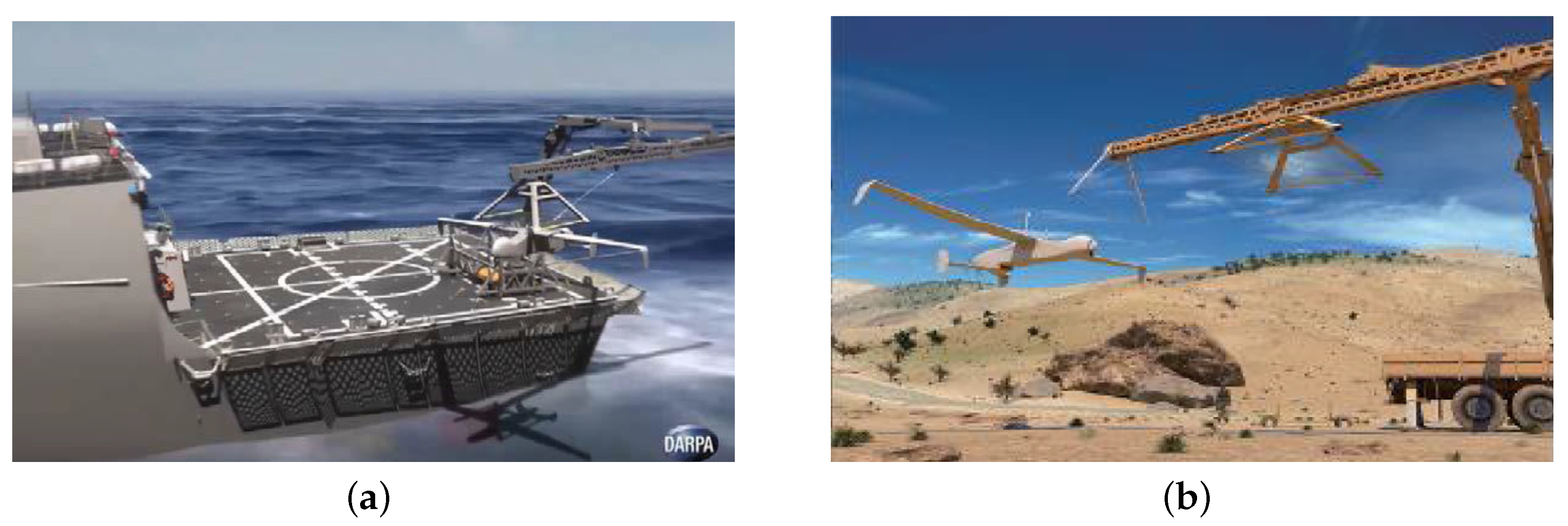
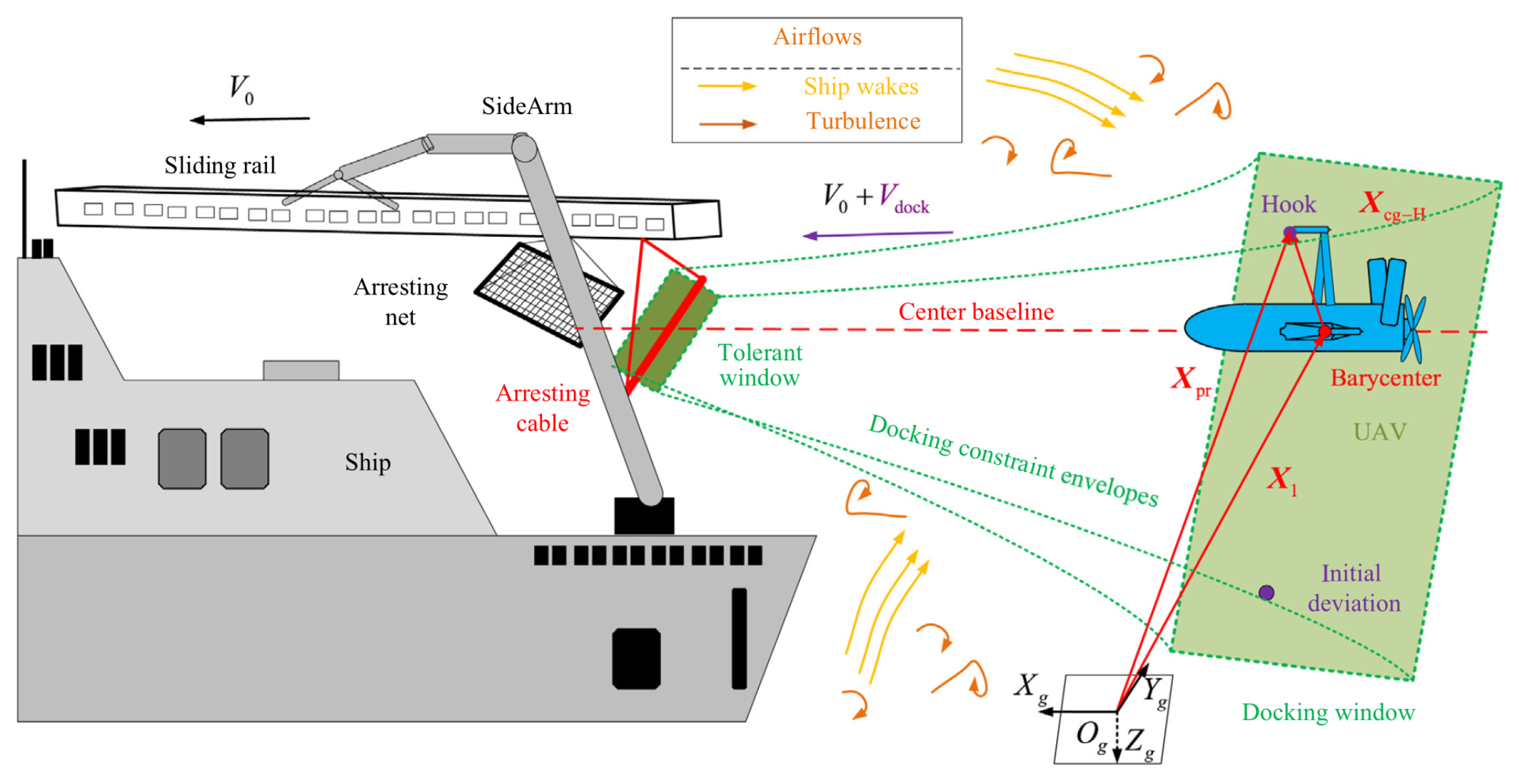
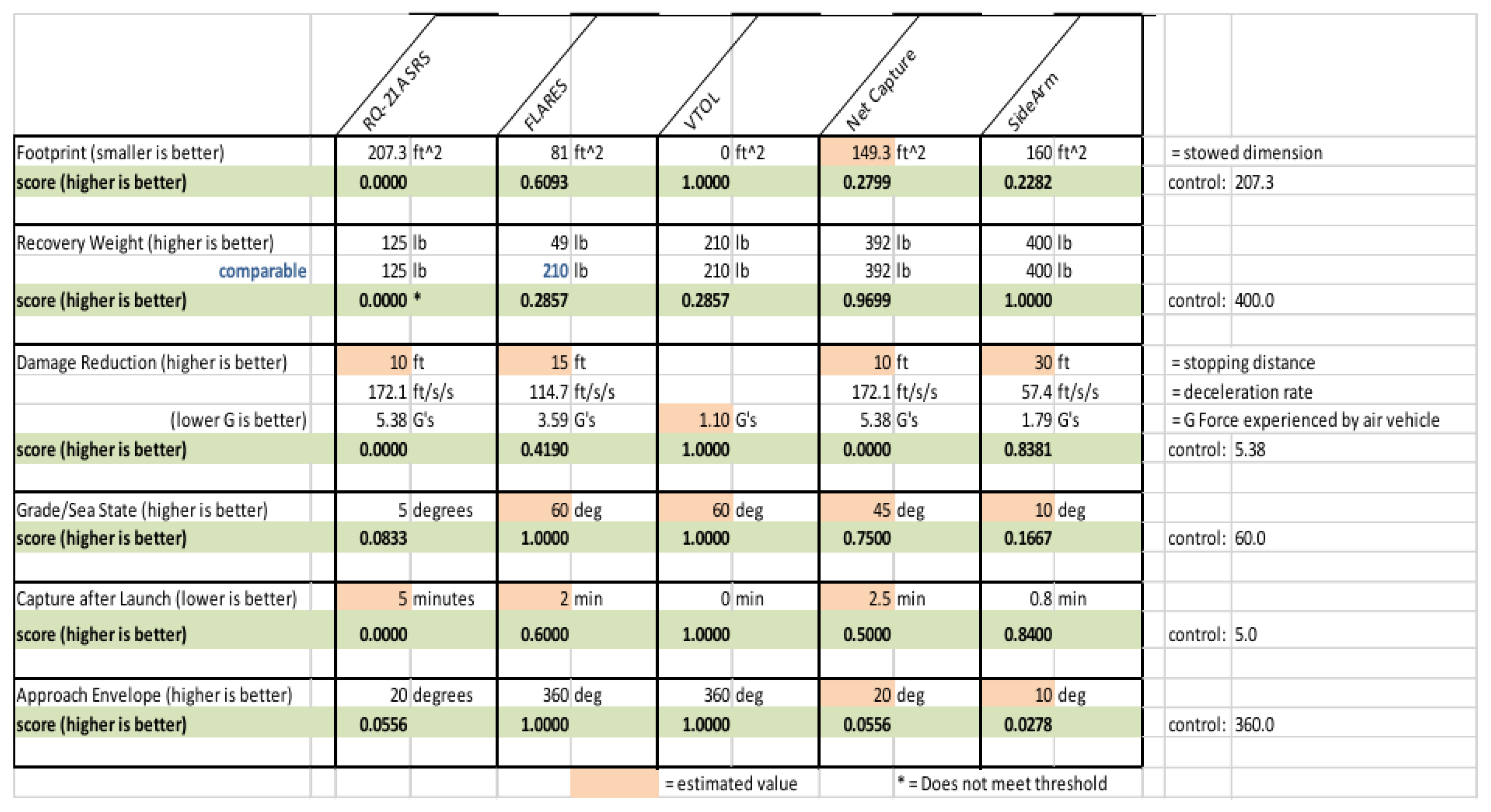
3.4. SideArm Recovery

The Defense Advanced Research Projects Agency (DARPA) and Aurora Flight Sciences first proposed and developed the SideArm recovery technology [54]. It is a prototype system similar to an inverted brake device. As shown in Figure 13, the SideArm recovery device consists of two parts. The horizontal traction rope at the front end of the crane captures the hook lock on the top of the UAV. After successful engagement, the brake device controls the aircraft to cause it to slow down. At the same time, the aircraft swings upward and is captured by the capture net at the tail end of the crane. The hook lock at the front end of the UAV is combined with the capture net so that the UAV is fixed on the traction rope and the capture net [55]. SideArm recovery requires high-quality real-time communication between the UAV and the ground control station. The grab points on the wings or fuselage must be strengthened. However, this method is unsuitable for fixed-wing UAVs with propellers in the nose because the UAV is captured and fixed by a capture net in the second phase.
Since SideArm technology is in the early stages of development and testing, most research on SideArm is based on STUAS recovery system (SRS) [55] and sea launch and recovery (SEALAR) [56] technologies. The SideArm device is a portable, universal, low-cost kit that can be independent of local infrastructure services and can quickly take off and recover UAVs from an aircraft carrier in various complex environments, thereby carrying and deploying air power anywhere in the world. According to official information released by DARPA [57], in December 2016, DARPA tested the SideArm technology demonstration system and successfully captured a approximately 181.5 kg Lockheed Martin Fury UAV. The system is also capable of recovering aircraft weighing up to approximately 500 kg. Su et al. [58] combined the shipborne SideArm system and the environmental flow field to establish an affine nonlinear dynamic model of the hook and modelled the SideArm UAV recovery dynamics.
The dynamic model is shown in Figure 14. It addresses the tracking lag problem when a fast-moving UAV attempts to dock with the SideArm, improving the docking accuracy and speed. In addition, Eriksson et al. [59] proposed a conceptual design of a paraglider recovery device similar to SideArm, which can also be migrated in multiple scenarios at low cost.
As shown in Figure 15, the Naval Postgraduate School (NPS) scores VTOL, Net Capture, SideArm, and other recovery technologies based on multiple factors such as cost, success rate, and damage to the UAV [55] and considers SideArm to be the UAV recovery technology with the highest comprehensive potential.
As a new UAV recovery method proposed in recent years, SideArm recovery uses a standard recovery device to achieve UAV recovery in various scenarios. It is expected to become a portable and universal method for UAV recovery. However, due to insufficient research and testing, it can only partially replace traditional UAV recovery methods.

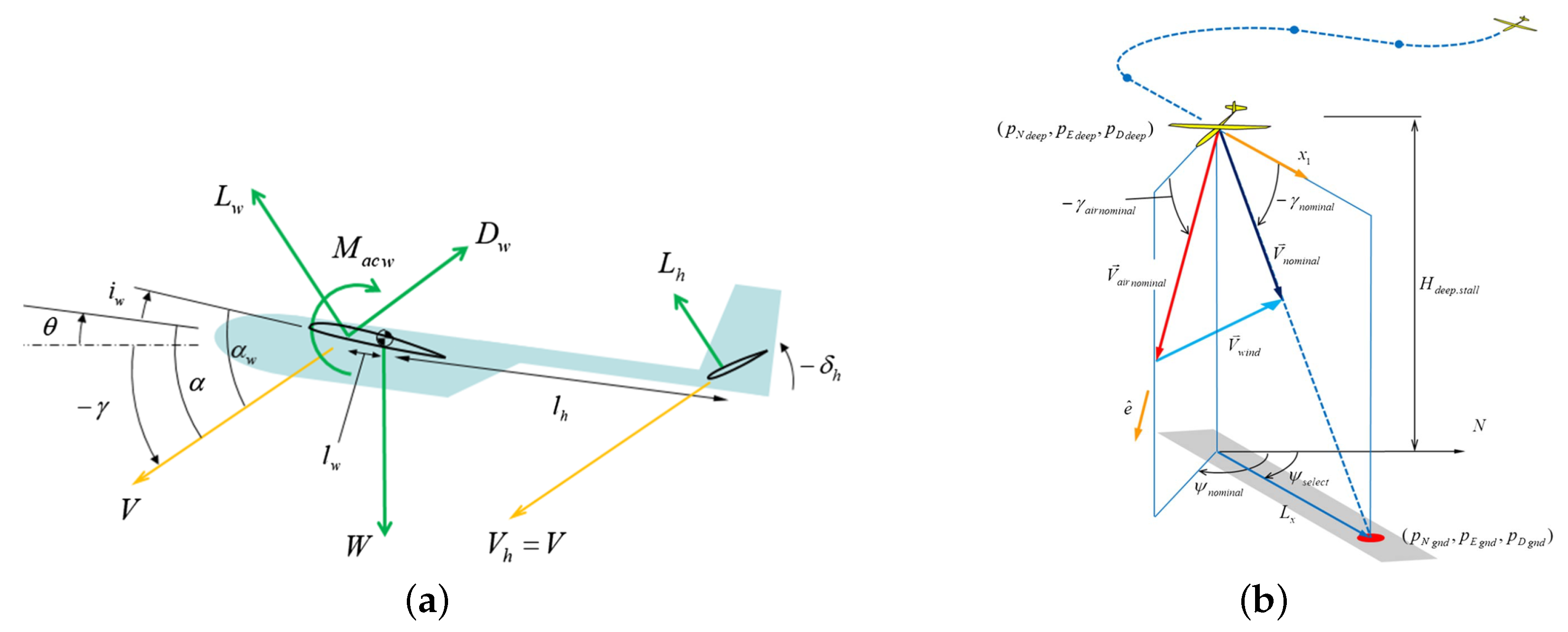
3.5. Deep Stall Recovery

Deep stall recovery [60] is a technology that uses the drag generated by continuous and stable deep stall maneuvers to offset the gravity of the UAV during landing, thereby safely and accurately recovering the UAV in confined spaces such as cities and forests [61]. Deep stall recovery has high requirements for the configuration and maneuverability of the UAV. The full-motion horizontal tail and high-precision attitude control in the stall state are necessary conditions to ensure the success of deep stall recovery. However, the position of the engine is not very important for UAVs. Therefore, deep stall recovery is generally used to recover small fixed-wing UAVs with high maneuverability.
As shown in Figure 16, during a deep stall recovery, the UAV descends at a steep heading angle while keeping the pitch angle as horizontal as possible. Finally, it impacts the ground and lands at a relatively low speed.
When a UAV is in a deep stall, it is easy to lose stability when subjected to crosswind and shear wind. In order to accurately calculate and simulate the process of deep stall landing of UAV, domestic and foreign scholars have made some attempts in recent years and achieved good results. Shao et al. [64] considered the multiple operating and terminal constraints of deep stall landing of UAVs and used the Radau pseudo-spectral method to generate the optimal landing trajectory. Warren et al. [65] designed a landing path based on the trochoid, which effectively ensured the forced landing of the UAV in an emergency. Gryte [66] used the Dryden turbulence model to model the environmental wind and successfully simulated the post-stall recovery process of the X8 UAV model. Cheng et al. [67] successfully simulated the trajectory of a deep stall landing of a UAV in an atmospheric turbulent environment by solving the unsteady flow equations coupled with 6-DOF motion.
The deep stall of UAVs has high accuracy and can be used for autonomous recovery at a fixed point [68]. Sathitwattanasan et al. [69] used the GPS and vision method to improve the landing point distance accuracy of the UAV’s deep stall recovery by 38.3% compared with manual operation. Zhen et al. [70] constructed the deep stall landing aerodynamic characteristics and trajectory tracking strategy of a small fixed-wing UAV assisted by deformable components. They verified the feasibility of the method through simulation experiments. Park et al. [71] predicted the advance feedback amount of wind field design, as shown in Figure 17, thereby improving the stability of the UAV during the deep stall process.
Deep stall recovery technology has high requirements for the performance of UAVs. In order to enter deep stall maneuvers stably, the UAV needs to have a full-moving horizontal tail with a large deflection angle and must enter the deep stall state through specific maneuvers. Deep stall recovery can solve the problem of accurate recovery of UAVs in narrow spaces. However, it challenges the anti-interference control and guidance of UAV deep stall motion.

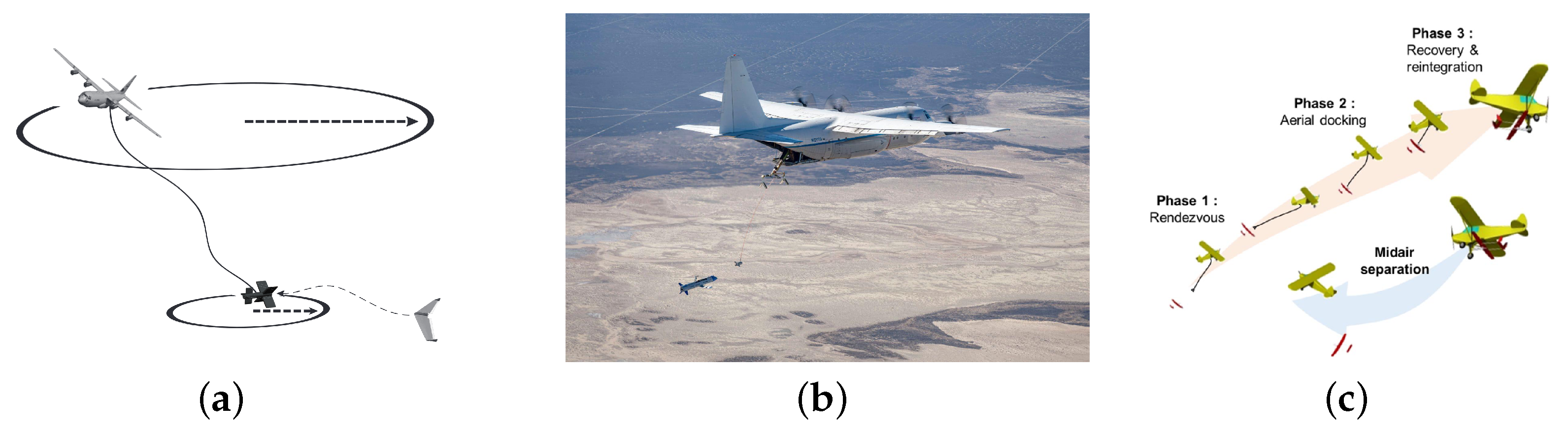
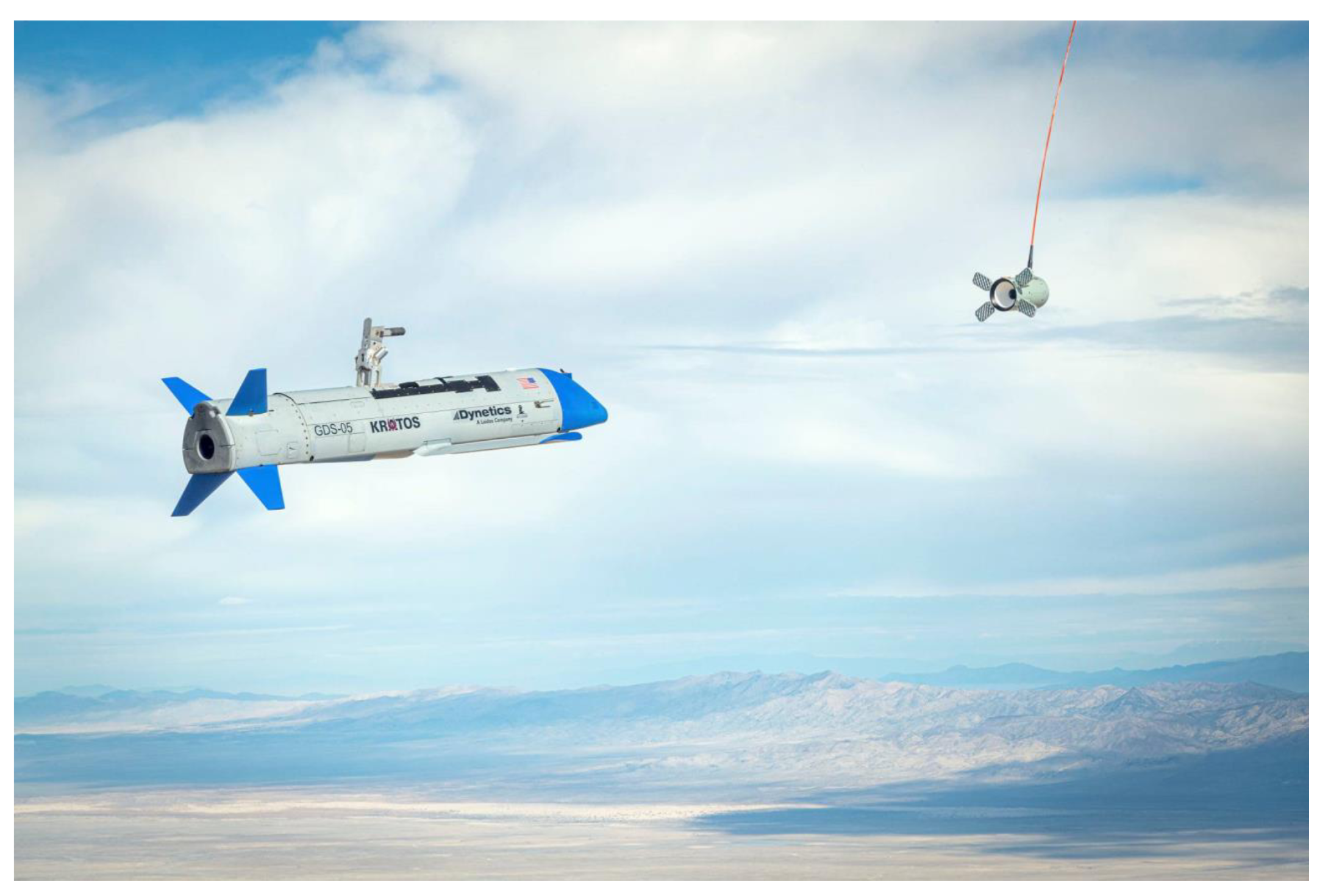
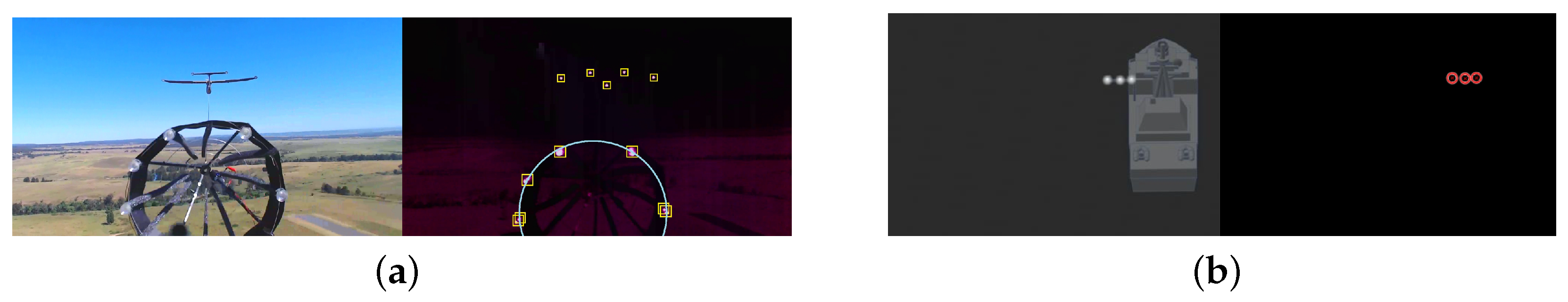
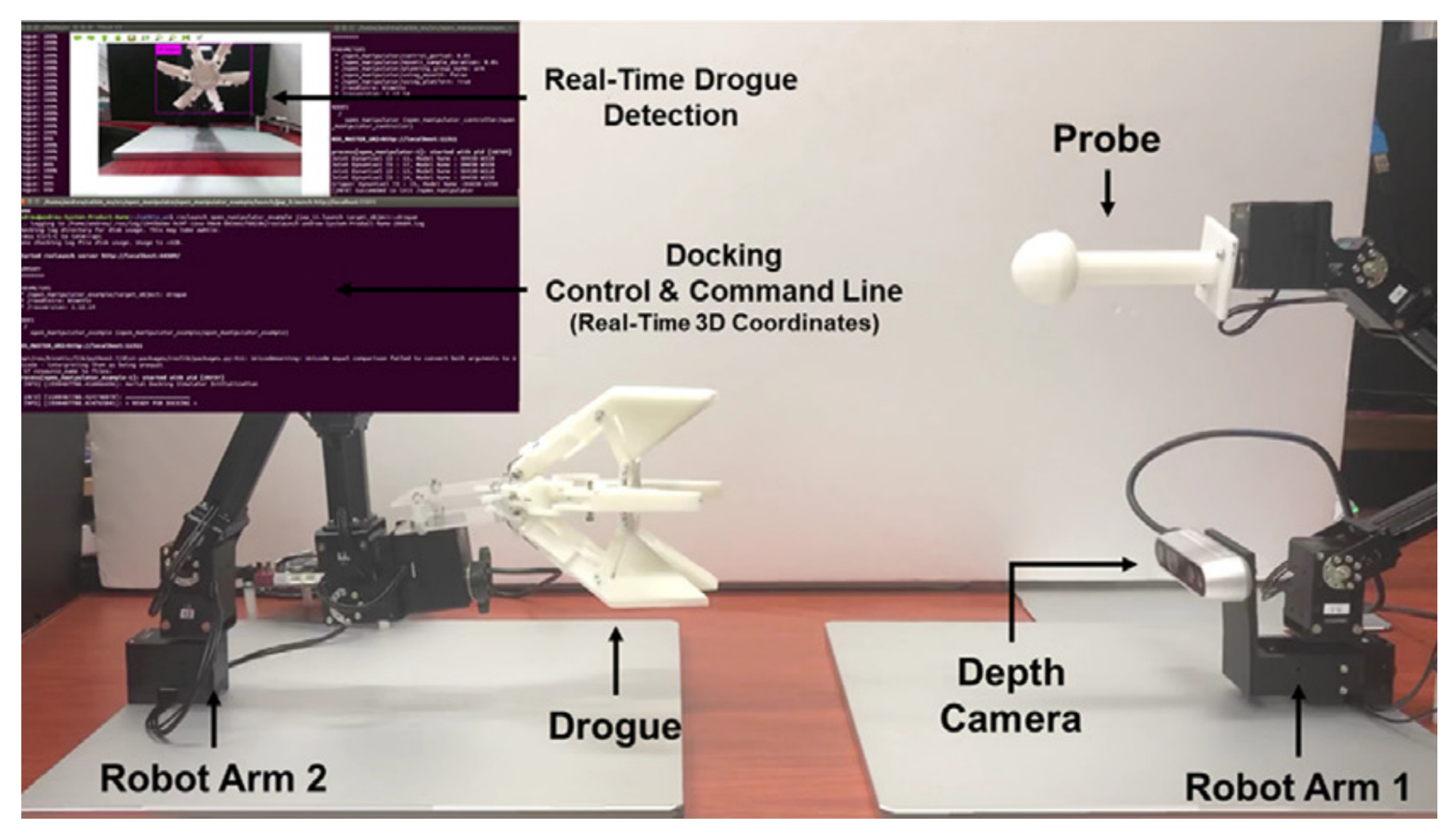
3.6. Towed Drogue Docking Recovery

One method of recovering fixed-wing UAVs is to use a flexible cable to tow a drogue to dock and recover two UAVs [72,73,74,75,76]. Typically, a large UAV is equipped with a towed cable, with a drogue at the end of the cable, and the small UAV to be recovered is equipped with a docking device to dock with the drogue to recover the small UAV. This method of using a towed drogue to complete recovery through docking is usually used for airborne recovery of UAVs. Figure 18 shows the system design diagram of this recovery method. Due to limitations in the docking structure, this recovery method only applies to UAVs with rear engines.
The key to a towed drogue docking recovery system is how to complete the docking of two UAVs [77]. Currently, there have been many studies on the aerial docking of UAVs. According to the structural classification of the docking drogue part, there are currently a variety of mechanical structures, including capture docking devices similar to the shape of the drogue used for airborne refueling and docking devices that use a gripper-type mechanism for locking.

3.6.1. Docking With a Stabilization Docking Drogue

The stabilization docking drogue [78,79] is similar in appearance and structure to the refueling drogue used in aerial refueling and is equipped with drag surfaces to increase stability.
In April 2016, DARPA announced that it had designed a recovery system for its “Gremlins” UAV [80]. The C-130 and X-61 Gremlins Air Vehicles demonstrated this aerial recovery system in flight in November 2021 [81]. Figure 19 shows the docking recovery process. The system has a docking drogue that can passively enhance stability and an electric mechanical clamp installed inside [73]. After the X-61 UAV is firmly connected to the docking drogue, called “Bullet,” the UAV shuts down its engine and folds its wings. The UAV is then recovered into the cabin of the C-130 through a complex recovery device.
In order to make the docking drogue more stable, Ferrin et al. [72] proposed a canard layout, as shown in Figure 20, in which the main wing is an X-shaped layout equipped with control surfaces for active stability augmentation control [82].

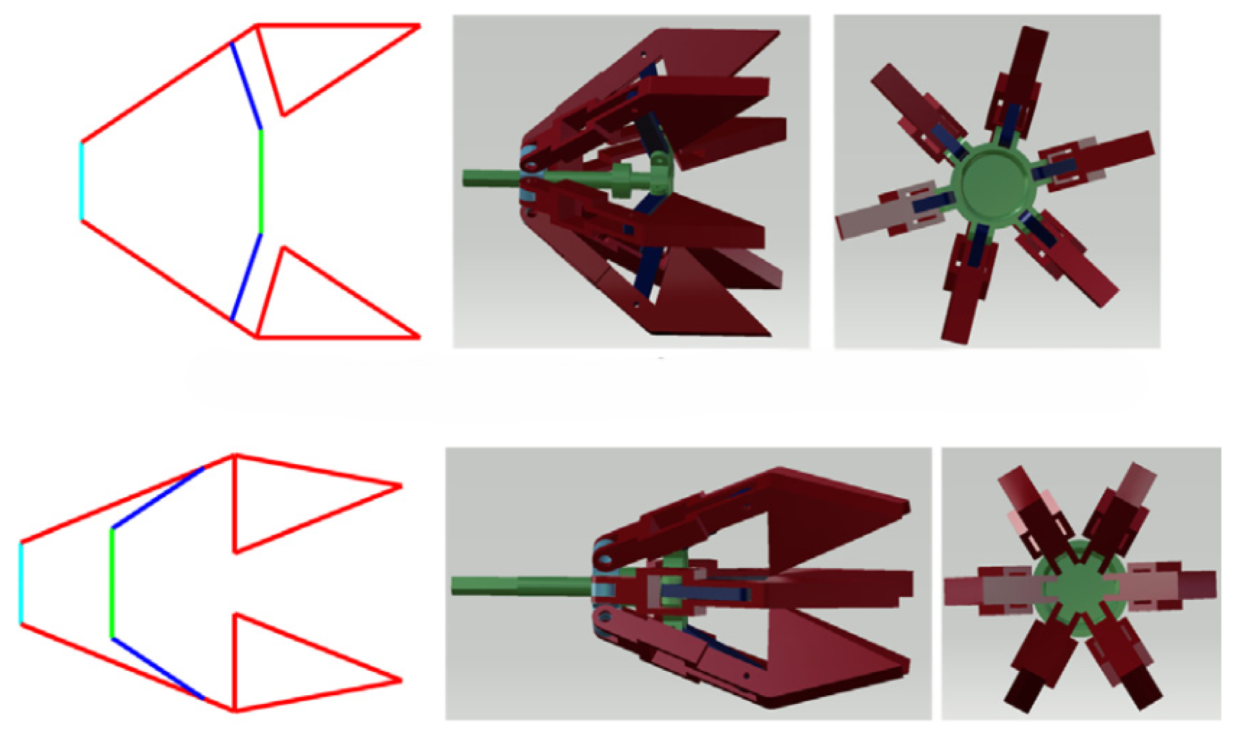
3.6.2. Docking with Foldable Bistable Gripper Trunnion

Choi et al. [83] designed a probe-and-drogue type docking mechanism that uses a bistable mechanism design to improve the robustness of the UAV during the docking process. Figure 21 shows the two stable states of the docking mechanism. The mechanism is in the open state before the UAV completes the docking and in the closed state after the UAV completes the docking.
The towed drogue docking recovery has broad application prospects in the airborne recovery of UAVs and is currently a hot research topic in the field of airborne recovery. Subsequent research should focus on the attitude perception of the drogue, the drogue docking control method, and the scheduling coordination between the recovery platform and UAVs. At the same time, this recovery method’s direct field test cost is relatively high, and how to carry out effective ground or dynamic platform simulation tests also needs to be explored. With the continuous improvement of technology, this recovery method will be more widely used.

3.7. Robotic Arm Recovery

Robotic arms to recover UAVs on ships and in the air have been widely used [84,85]. Depending on the location of the robotic arm, one type of recovery is passive recovery, which relies on the robotic arm installed on ships, the land, or large aircraft or airships to complete the grabbing and recovery of the UAVs actively. This recovery method usually involves installing a retrieval device on the nose or front of the fuselage to complete the recovery. Therefore, it is primarily used in UAVs with rear engines. Another type of active recovery usually relies on the robotic arm installed on the UAV itself. Figure 22 shows an example of this recovery method, which actively grabs the location where the UAV needs to dock to complete the recovery. This type of recovery method is also called perching [86]. According to the installation position of the robotic arm, it is divided into a nose-type robotic arm and a belly-type robotic arm. The nose-type robotic arm is suitable for UAVs with a rear engine, whereas the belly-type robotic arm is suitable for UAVs with front propellers.

3.7.1. Passive Recovery Method of Robotic Arm

This type of recovery method relies on the movement of a robotic arm to capture the UAV. Yu et al. [84] designed a recovery system based on a robotic arm and conducted experiments in a shipborne marine environment. The critical point of the recovery system is to control the robotic arm to reach the final coordinate position from the initial point smoothly and avoid collision between the robotic arm and other shipborne equipment during movement.
Inspired by the predatory behavior of web-casting spiders, Wu et al. [87] designed a cable-driven parallel robotic arm for aerial recovery of UAVs, which can dynamically adjust its spatial position to intercept and recover UAVs. As shown in Figure 23, the recovery device consists of a rigid telescopic rod and four symmetrically arranged cables. The electric telescopic rod uses two rotating joints between the telescopic rod and the platform to achieve pitch and yaw motion, thereby completing the recovery device’s position control.

3.7.2. Active Recovery Method of Robotic Arm

Different from the passive recovery method, the active recovery system is usually airborne, and the UAV can actively complete the recovery and perch process. It focuses on the structural design of the robotic arm and the matching of the motion state of the robotic arm and the UAV.
Inspired by birds, Nagendran et al. [88] designed a landing gear similar to bird legs, which avoids the difficulty of fixed-wing UAVs landing on runways. It enables UAVs to land in unknown environments, cushion impacts, and successfully complete perching landings by using a landing gear similar to bird legs. Figure 24. shows the basic structure of this landing gear and its comparison with bird legs.
Similarly, Stewart et al. [89] imitated birds’ claws and designed a grabbing mechanism that enables a fixed-wing UAV to grab a target object when flying over it. They then installed this grabbing mechanism on the head of the UAV and realized the perching recovery of the UAV by grabbing a round bar-shaped object. The system consists of a storage mechanism for energy recovery and a claw for perching on a horizontal bar [86], whose structure is shown in Figure 25. Compared with the recovery method through a deep stall at a high angle of attack, this method reduces the difficulty of energy control. It can complete recovery at a larger yaw angle.
Mehanovic et al. [90,91] designed a bionic leg structure that enables a fixed-wing UAV to perch and recover on a rough vertical wall, allowing it to land smoothly and robustly on the wall. Figure 26 shows this process.
In general, the research on robotic arm recovery is currently mainly carried out on micro-UAVs. It is a recovery method that requires high precision in both the gripping structure design of the fixed-wing UAV itself and the docking control of the UAV. Currently, the technology is not yet fully mature, and research needs to be continuously improved and deepened.

4. Path Planning and Guidance Technology in the Pre-Recovery Process

The recovery process of a UAV is typically divided into pre-recovery and final recovery stages. In the pre-recovery stage, there is a significant distance between the UAV and the recovery device. It is important to establish appropriate recovery strategies and trajectories at this stage. An efficient and safe trajectory must allow the UAV to approach the recovery device quickly. Depending on the recovery method, the recovery device can be either mobile or fixed, each with different motion states. The two different recovery devices have varying requirements for the efficiency and robustness of the UAV’s path planning method. The following section will introduce relevant path planning and guidance technical methods in fixed-wing UAV recovery.

4.1. Linear Planning

For fixed recovery devices, the recovery path of the UAV is fixed and is only affected by the weather and the terrain of the deployment location. Therefore, the linear planning algorithm in the mathematical model method is often used [35,37,38] to guide the UAV to fly to the recovery device for precise final docking. Mathisen et al. [62] used the Dubin algorithm to plan the trajectory in the deep stall recovery method. The above path planning method is simple and efficient, does not require complex models, and has high real-time performance. However, its adaptability to environmental changes could be improved, and the accuracy of guidance is easily affected.

4.2. LOS Guidance

LOS guidance measures the line of sight angle between the UAV and the recovery device, transforming the path planning problem into an angle error control problem and guiding the UAV to complete the pre-recovery flight. This method applies to dynamic [39] and static [63] recovery devices, but its disadvantages are also apparent. LOS guidance relies heavily on the input of visual information. When obstacles or vision blocks are present, the recovery device is disturbed, and it cannot complete the guidance of the target.

4.3. Multi-Objective Optimization

Zeng et al. [60] proposed a method to plan the optimal trajectory based on the Gaussian pseudo-spectral method under constraints like terminal speed, sinking rate, terminal attitude, downward approach range, input saturation, etc. They completed the deep stall recovery of the UAV. Similarly, Warren et al. [65] designed a multicriteria decision-making (MCDM) algorithm to design the recovery trajectory in deep stall recovery. The multi-objective optimization path planning and guidance method takes into account multiple conditions at the same time, which can meet the optimization and control of the state and environment during the recovery process of the UAV.

4.4. Machine Learning Methods

With the development and application of artificial intelligence, reinforcement learning and deep learning can be applied to the path planning and guidance process of UAVs. Zhao et al. [75] proposed a new potential function-based reinforced reward control method (PRL), which can be used for trajectory generation under non-convex constraints, ensuring convergence while satisfying safety constraints. Su et al. [58] proposed a neural network adaptive constraint docking control algorithm to recover UAVs in harsh marine environments and different initial positions. Such algorithms usually have good anti-interference ability, fast-tracking performance, and safe constraint control capabilities.

4.5. Path Planning and Guidance Based on Heuristic Algorithms

Heuristic path planning methods [92] include the ant colony algorithm, genetic algorithm, particle swarm algorithm, simulated annealing algorithm, artificial potential field, and other methods. Liu et al. [93] used a genetic algorithm to design the path for UAV cluster recovery and achieved efficient and accurate scheduling. This method suits complex path planning scenarios and has good global search capabilities.

5. Position and Attitude Control Methods During the Recovery Process

The automation of fixed-wing UAV recovery requires the support of various vital technologies. Key aspects include path planning, automatic control of position and attitude, and relative position perception technology between the UAV and the recovery device during recovery. In the final recovery stage, precise control of the position and attitude of the UAV is necessary to ensure that the recovery device can accurately capture the UAV. The following discusses the current position and attitude control methods for the automatic recovery of fixed-wing UAVs.

5.1. Classical Control Algorithms

Classical control is the industry’s most mature and widely used linear control method. It includes proportional-integral-derivative (PID), linear quadratic regulator (LQR), the root locus method, the frequency response method, and other control algorithms. It has the advantages of simple structure, easy implementation, and parameter adjustment, and it is not overly dependent on accurate mathematical models. However, classical control has a poor control effect on nonlinear models and poor robustness in complex environments. In fixed-wing UAV recovery technologies such as net recovery and parachute recovery, which have relatively low requirements on UAV anti-disturbance and precise modelling, classical control algorithms have been widely used and have performed excellently.
Mark et al. [78] used the classic PID control algorithm to control the longitudinal direction of the UAV, improving the trajectory tracking accuracy during the recovery process of the UAV. Jeffrey et al. [72] used PI control for active tracking and docking of drogue recovery. Zhang [36] et al. used the proportional navigation (PN) method to perform open-loop control of the UAV and gave the adjustment formula of the control parameters, achieving good control results. Seungho et al. [35] used a cubic polynomial in the pseudo-pursuit landing guidance law to generate sequential imaginary landing and approaching points, enabling the UAV to land more accurately and smoothly at the designated location.
Thanks to the characteristics of fast parameter adjustment and rapid deployment of classical control, classical control algorithms are still widely used in the test flights and technical verification of small and medium-sized micro UAVs. The classical control method provides a simple and effective control method and excels in high precision and robustness in windless or straightforward environments. One must select appropriate control algorithms according to specific application scenarios and requirements to ensure the safety and reliability of the UAV recovery process. In addition, applying classical control algorithms in fixed-wing UAV recovery still faces some challenges. For example, in complex wind fields and special maneuvers, the UAV’s dynamic linear model was established, and the system was robust and had anti-interference ability.
In general, the application prospects of classical control algorithms in fixed-wing UAV recovery are broad. However, they must be continuously optimized and improved to adapt to the ever-changing flight environment and technical requirements.

5.2. Modern Control Algorithms

Compared with classical control algorithms, modern control algorithms have significant advantages in processing complex systems, improving system robustness, and adapting to nonlinear systems, including adaptive control, robust control, sliding film control, etc. More and more studies use modern control methods to improve classical control algorithms, such as PID and LQR, and have achieved good control results.
Su et al. [77] proposed a finite-time prescribed performance control (FPPC) algorithm combined with a backstepping control law to improve the trajectory tracking accuracy of a UAV during its recovery process. Kristoffer et al. [39] used L1 adaptive control to improve the flight attitude control of a UAV and the system’s robustness.
Modern control methods have broad application prospects in fixed-wing UAV recovery. Adaptive control and robust control provide high robustness and flexibility and are suitable for complex and highly uncertain environments; fuzzy control and neural network control can handle nonlinear and complex systems and provide high-precision control strategies; model predictive control performs well in trajectory tracking and attitude control. Compared with classical control methods, these algorithms provide higher accuracy and robustness in the UAV recovery process, ensuring that the UAV can land safely and accurately in complex environments.

5.3. Intelligent Control Algorithms

Intelligent control algorithms integrate machine learning, artificial intelligence, and other technologies to achieve autonomous control and intelligent decision-making of complex systems. These algorithms include nonlinear control algorithms such as fuzzy control, neural network control, and genetic algorithms.
Nie et al. [46] designed an active, flexible capture system based on fuzzy PID control and combined it with a robotic arm and a UAV catapult to achieve automatic release. Su et al. [58] proposed a direct control concept for SideArm recovery using MLP-based ESN approximators (MESNA) in UAV flight control. Wang et al. [76] used neural adaptive coordinated docking control to effectively solve the singularity problem of command switching.
The application of intelligent control algorithms in fixed-wing UAV recovery is still concentrated in the research stage. Neural networks and fuzzy control can handle nonlinear and complex systems and provide high-precision control strategies; genetic and particle swarm algorithms perform well in global optimization and complex environments. These algorithms have particular application value in nonlinear and complex systems scenarios.

5.4. Predictive Control Algorithms

Model predictive control (MPC) achieves optimal control by predicting the system’s behavior in the future and optimizing the control input. During the UAV’s recovery process, MPC can provide high-precision trajectory tracking and attitude control to ensure the UAV’s stable flight in complex environments. Its advantages lie in optimal performance and multivariable processing capabilities, but real-time optimization problem solving requires high computational effort and computing resource requirements.
Mathisen et al. [61] proposed a constrained nonlinear model predictive control (NMPC), which uses the predicted value of the wind field in a complex environment as the system’s prediction variable to achieve a safe landing at a maximum wind speed of 7 m/s. In 2020, Mathisen et al. continued to apply NMPC to the longitudinal control of deep stall recovery UAVs [62], controlling the landing point accuracy of deep stall recovery UAVs to within 10 m.

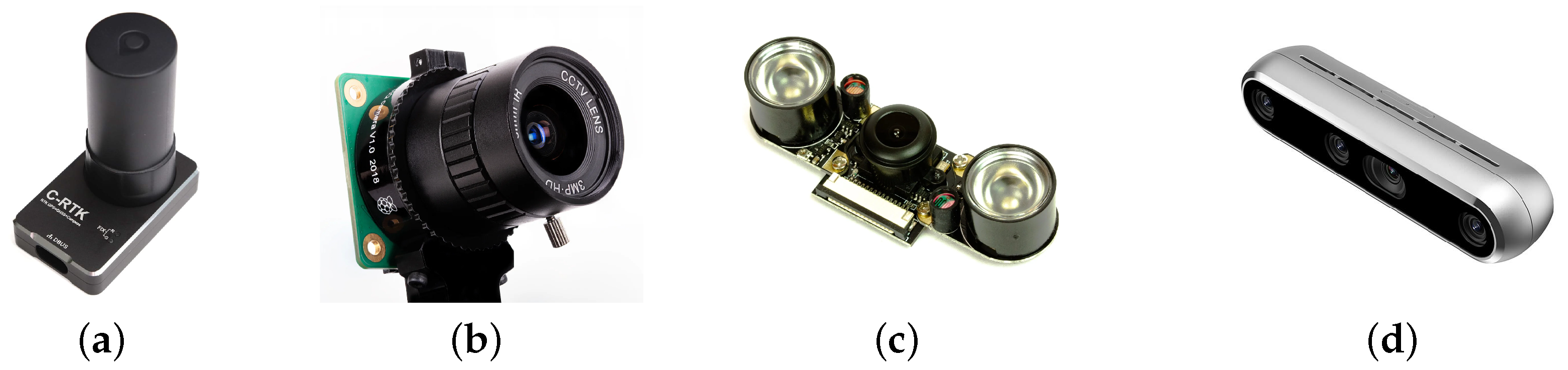
6. Relative Position Sensor of Recovery
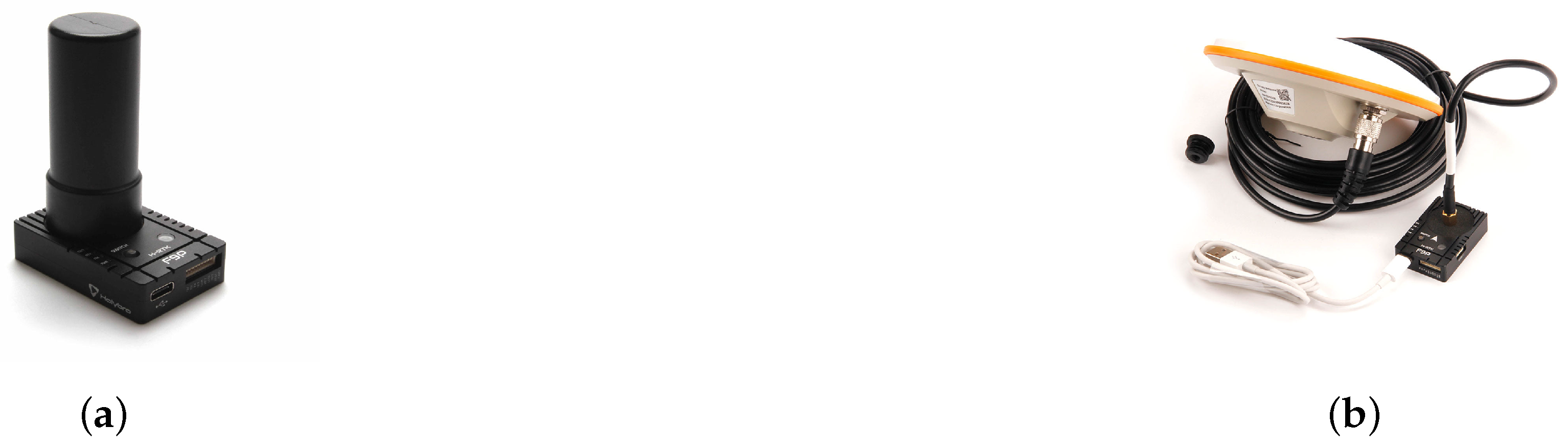
During the recovery process of a fixed-wing UAV, it is crucial to achieve relative position awareness between the UAV and the recovery device or the planned recovery location. Therefore, it is necessary to summarize the types of sensors involved to form a more comprehensive technical analysis of the recovery process. After a survey of research, it was found that the widely used sensors mainly include global navigation satellite system (GNSS) [37,38], visible light camera [73], IR camera [45], and depth camera [83]. Figure 27 shows examples of these sensors.

6.1. GNSS

GNSS can provide UAVs with accurate position feedback for their navigation and the recovery platform. Many studies have used GPS modules under the GNSS system to achieve autonomous recovery of UAVs [63,78,82]. Conventional GNSS positioning technology can only provide meter-level positioning accuracy, and real-time kinematic (RTK) GNSS technology improves positioning accuracy. RTK GNSS is a navigation technology that uses the carrier of the incoming signal from the satellite and compares the signal with the signal received by the base station. Calculating the phase shift between the rover and the base station can provide centimeter-level positioning accuracy by calculating the phase shift between the UAV, which is the rover, and the base station. Many studies have achieved high-precision UAV recovery based on RTK GNSS positioning sensors [39,40,48]. RTK GNSS modules are standard in various fixed-wing UAVs, and their low-cost advantage can also meet the needs of a wide range of applications. However, RTK GNSS technology relies on the correction of positioning base stations, and the deployment of positioning base stations has brought inconvenience to a certain extent. Network RTK services provide a specific solution to this defect [98], but it still needs to be considered based on the regional restrictions of network RTK services.
In addition, it is necessary to be particularly careful when setting up base stations on mobile platforms, such as ships that may move. Usually, the ship needs to be treated as a rover, and a land-based base station is used to provide correction signals [38]. An example of a base station and a mobile terminal for RTK GNSS is shown in Figure 28.

6.2. Visible Light Camera

Visible light cameras are usually used for drogue recognition and relative position feedback during the towed drogue docking recovery process. Many studies have achieved relative position feedback of the drogue by installing a visible light camera on the UAV [73,74,82]. It is usually necessary to integrate the GNSS measurement values of the UAV for data fusion to achieve more accurate drogue pose estimation. In addition, with the continuous advancement of UAV aerial recovery technology, how to achieve higher frame rate and higher precision drogue recognition based on visible light cameras has become the critical point of the following research [100]. Figure 29 shows an example of drogue recognition based on a visible light camera.

6.3. IR Camera

IR cameras are usually used in conjunction with infrared beacons for recovery guidance. By deploying infrared beacons in specific geometric shapes, the IR camera can perform relatively accurate image thresholding processing, and the beacon feature extraction algorithm can be used to detect the recovery mechanism accurately. This method has the advantages of night visibility and low cost. However, it is necessary to avoid the problem of blocking infrared beacons, and strict IR camera selection must be performed to adapt to the deployment method and configuration of infrared beacons. This sensor has been verified to a certain extent in the airborne drogue docking process [101]. A simulation of UAV recovery based on a ship was also carried out using this method [45]. Figure 30 shows an example of an IR camera and infrared beacon application.

6.4. Depth Camera

A depth camera is a three-dimensional camera with accurate distance measurement. It can superimpose distance information on the image’s color information and has apparent advantages in spatial perception. The detection and position feedback of recovery device components based on depth cameras is a relatively new research direction [83,84] and is still in the simulation and laboratory testing stage. A method for real-time target detection and tracking based on deep learning and depth cameras has been proposed, and a simulation test has been conducted for the UAV aerial docking recovery scenario [83]. Figure 31 shows this example.
The application of depth cameras in UAV recovery provides a new practice. However, conventional depth cameras still have certain limitations regarding distance perception range, usually within 10 m. In future research, developing and selecting depth cameras for different UAV specifications and recovery scenarios is necessary.

7. Discussion and Future Research Directions

Based on a comprehensive literature review, we analyze different recovery methods’ applications and technical characteristics and discuss future research directions for fixed-wing UAV runway-free recovery. To more comprehensively evaluate the characteristics of various recovery methods, this paper evaluates them from two perspectives: application scenarios and technical factors. Table 2 gives a detailed analysis of the application scenarios of various recovery methods.
Table 3 gives a detailed analysis of the technical characteristics of various recovery methods. This paper defines and classifies fixed-wing UAVs according to their take-off weight, defining UAVs weighing less than 2 kg as micro, 2–15 kg as mini, 15–150 kg as small, 150–600 kg as medium, and more than 600 kg as large [102].
Table 4 gives a detailed analysis of the technical characteristics of various control algorithms to further summarize the advantages and disadvantages of various control algorithms in UAV recovery and their applications in the seven UAV recovery technologies proposed in Section 3.
The main characteristics and applicable scenarios of various sensors are summarized, as shown in Table 5.
From the above analysis, it is necessary to select appropriate sensors based on application scenarios and cost constraints when designing and implementing the recovery system. At the same time, to further improve the robustness of position detection during the recovery process, multi-sensor fusion processing and position perception will become the next research focus.
While attempting to cover recent advancements in fixed-wing UAV runway-free recovery technologies, this study has certain limitations:
  • Due to the study’s scope, the primary focus is on fixed-wing UAV technologies for runway-free recovery developed in the last 20 years, excluding earlier methods such as airbag recovery.
  • The limitations of the classification method have resulted in relatively few application scenarios, such as closed indoor spaces and environments with limited GPS or vision, like tunnels.

Future Research Directions

There are many challenges of runway-free recovery for fixed-wing UAVs, including recovery automation level, adaptability to the environment, safety, swarm, and collaboration.
  • Improvement of Recovery Automation Level
    Process automation has been achieved according to the recovery methods summarized in this research, such as SideArm and drogue docking recovery. For the future, it is still necessary to consider achieving a higher level of automation in designing recovery devices based on the existing recovery methods. For example, the literature [47] has combined the robotic arm with rope recovery to achieve the UAV reset problem after the UAV is successfully recovered, thereby helping to improve the efficiency of the UAV’s subsequent launch missions and reduce the labour input after recovery. In this regard, we can learn from the current multi-rotor UAV docking station design concept [103,104], combined with the particular scenario requirements of fixed-wing UAV recovery, to conduct the design and application exploration of recovery devices with higher levels of intelligence and automation.
  • Enhanced Adaptability to Recovery Environment
    At present, multi-sensor fusion has been able to achieve better position perception and spatial positioning during the recovery process. However, various sensors have certain defects under different working conditions. In some particular recovery scenarios, GNSS denial may occur [105]. Improving the adaptability and reliability of the recovery device in this environment may become an important research direction in the future.
  • Improved Recovery Safety
    During the net recovery and parachute recovery process, the UAV structure may be damaged due to the inadequate design of the buffering and energy absorption device. Therefore, how to solve the energy absorption, buffering, and collision avoidance problems during net recovery through the application of new structures and new materials remains to be explored further. In addition, due to the uncertainty of the landing point of parachute recovery, there may be obstacles, such as trees or buildings on the ground, which can easily cause structural damage to the UAV. A future research direction can also be how to avoid or minimize such risks.
  • Swarm and Collaboration
    With the improvement of recovery devices’ automation levels and the large-scale operation of swarm UAVs, swarm recovery will become a new research hotspot. Swarm recovery needs to consider important issues such as mission planning and conflict resolution of route space, and sufficient research needs to be conducted on the intelligent task scheduling of recovery devices.

8. Conclusions

This paper investigates the latest research progress in the runway-free recovery of fixed-wing UAVs in academia and industry. We comprehensively discuss the runway-free recovery methods, the path planning and guidance technology, the position and attitude control methods, and the critical sensors used. Our work comprehensively and effectively summarizes and evaluates various recovery methods, reveals the adaptation relationship between various recovery methods and application scenarios, and the mapping relationship between recovery methods and critical technologies. Judging from our research results, the technical complexity of parachute recovery, net recovery, and rope capture recovery is relatively low, but the level of total automation is not high. SideArm recovery, deep stall recovery, and towed drogue docking recovery are technically complex and can currently fully automate the recovery process. Robotic arm recovery still needs to improve in practical application due to its complex structure and immature technology. Therefore, future research on runway-free recovery should focus on process automation, adaptability to complex environments, and recovery security. Research on recovery technologies for fixed-wing UAV swarms should also be considered in future work. Our work comprehensively demonstrates the research interest of academia and industry in runway-free recovery of fixed-wing UAVs and the broad application value of related technologies. This paper also points out the research gaps in runway-free recovery and proposes future research directions.

Author Contributions

Writing—original draft, Y.L., Y.W. and H.L.; Writing—review and editing, H.L. and J.A. All authors have read and agreed to the published version of the manuscript.

Funding

This research received no external funding.

Conflicts of Interest

On behalf of all authors, the corresponding author states that there are no conflicts of interest.

References

  1. Lottes, P.; Khanna, R.; Pfeifer, J.; Siegwart, R.; Stachniss, C. UAV-based crop and weed classification for smart farming. In Proceedings of the 2017 IEEE International conference on Robotics and Automation (ICRA), Singapore, 29 May–3 June 2017; IEEE: Piscataway, NJ, USA, 2017; pp. 3024–3031. [Google Scholar]
  2. Boon, M.A.; Drijfhout, A.P.; Tesfamichael, S. Comparison of a fixed-wing and multi-rotor UAV for environmental mapping applications: A case study. Int. Arch. Photogramm. Remote Sens. Spat. Inf. Sci. 2017, 42, 47–54. [Google Scholar] [CrossRef]
  3. Hu, S.; Ni, W.; Wang, X.; Jamalipour, A. Disguised tailing and video surveillance with solar-powered fixed-wing unmanned aerial vehicle. IEEE Trans. Veh. Technol. 2022, 71, 5507–5518. [Google Scholar] [CrossRef]
  4. Elston, J.; Argrow, B.; Stachura, M.; Weibel, D.; Lawrence, D.; Pope, D. Overview of small fixed-wing unmanned aircraft for meteorological sampling. J. Atmos. Ocean. Technol. 2015, 32, 97–115. [Google Scholar] [CrossRef]
  5. Cai, G.; Lum, K.Y.; Chen, B.M.; Lee, T.H. A brief overview on miniature fixed-wing unmanned aerial vehicles. In Proceedings of the IEEE ICCA 2010, Xiamen, China, 9–11 June 2010; pp. 285–290. [Google Scholar]
  6. Abdelmaksoud, S.I.; Mailah, M.; Abdallah, A.M. Control strategies and novel techniques for autonomous rotorcraft unmanned aerial vehicles: A review. IEEE Access 2020, 8, 195142–195169. [Google Scholar] [CrossRef]
  7. Ducard, G.J.; Allenspach, M. Review of designs and flight control techniques of hybrid and convertible VTOL UAVs. Aerosp. Sci. Technol. 2021, 118, 107035. [Google Scholar] [CrossRef]
  8. Tian, P.; Chao, H.; Rhudy, M.; Gross, J.; Wu, H. Wind sensing and estimation using small fixed-wing unmanned aerial vehicles: A survey. J. Aerosp. Inf. Syst. 2021, 18, 132–143. [Google Scholar] [CrossRef]
  9. Ryu, H.; Park, S. Vision-based wind and position estimation with fixed-wing unmanned aerial vehicle. J. Guid. Control. Dyn. 2018, 41, 2283–2292. [Google Scholar] [CrossRef]
  10. Ziliani, M.G.; Parkes, S.D.; Hoteit, I.; McCabe, M.F. Intra-season crop height variability at commercial farm scales using a fixed-wing UAV. Remote Sens. 2018, 10, 2007. [Google Scholar] [CrossRef]
  11. Han, X.; Thomasson, J.A.; Bagnall, G.C.; Pugh, N.A.; Horne, D.W.; Rooney, W.L.; Jung, J.; Chang, A.; Malambo, L.; Popescu, S.C.; et al. Measurement and calibration of plant-height from fixed-wing UAV images. Sensors 2018, 18, 4092. [Google Scholar] [CrossRef] [PubMed]
  12. Templin, T.; Popielarczyk, D.; Kosecki, R. Application of low-cost fixed-wing UAV for inland lakes shoreline investigation. Pure Appl. Geophys. 2018, 175, 3263–3283. [Google Scholar] [CrossRef]
  13. Moudrỳ, V.; Urban, R.; Štroner, M.; Komárek, J.; Brouček, J.; Prošek, J. Comparison of a commercial and home-assembled fixed-wing UAV for terrain mapping of a post-mining site under leaf-off conditions. Int. J. Remote Sens. 2019, 40, 555–572. [Google Scholar] [CrossRef]
  14. Beard, R.W.; McLain, T.W.; Nelson, D.B.; Kingston, D.; Johanson, D. Decentralized cooperative aerial surveillance using fixed-wing miniature UAVs. Proc. IEEE 2006, 94, 1306–1324. [Google Scholar] [CrossRef]
  15. Roberge, V.; Tarbouchi, M.; Labonté, G. Fast genetic algorithm path planner for fixed-wing military UAV using GPU. IEEE Trans. Aerosp. Electron. Syst. 2018, 54, 2105–2117. [Google Scholar] [CrossRef]
  16. Kügler, M.E.; Heller, M.; Holzapfel, F. Automatic take-off and landing on the maiden flight of a novel fixed-wing UAV. In Proceedings of the 2018 Flight Testing Conference, Savannah, GA, USA, 25–29 June 2018; p. 4275. [Google Scholar]
  17. Yafei, L.; Qingyang, C.; Gaowei, J.; Zheng, G. Development and experiment of elastic-rope launcher for small fixed-wing UAVs. In Proceedings of the 2020 3rd World Conference on Mechanical Engineering and Intelligent Manufacturing (WCMEIM), Shanghai, China, 4–6 December 2020; IEEE: Piscataway, NJ, USA, 2020; pp. 654–658. [Google Scholar]
  18. Fan, Y.; Ding, M.; Cao, Y. Vision algorithms for fixed-wing unmanned aerial vehicle landing system. Sci. China Technol. Sci. 2017, 60, 434–443. [Google Scholar] [CrossRef]
  19. Kong, W.; Zhou, D.; Zhang, Y.; Zhang, D.; Wang, X.; Zhao, B.; Yan, C.; Shen, L.; Zhang, J. A ground-based optical system for autonomous landing of a fixed wing UAV. In Proceedings of the 2014 IEEE/RSJ International Conference on Intelligent Robots and Systems, Chicago, IL, USA, 14–18 September 2014; IEEE: Piscataway, NJ, USA, 2014; pp. 4797–4804. [Google Scholar]
  20. Manta Air. UAV Safety and Recovery Systems. 2024. Available online: https://manta-air.com/uav_safety_and_recovery_systems/ (accessed on 27 July 2024).
  21. Paul, P.; Paul, L. An overview on the parachute recovery systems with additive manufacturing for UAV safe landing. Mater. Today Proc. 2023, 72, 3158–3162. [Google Scholar] [CrossRef]
  22. Wu, H.; Wang, Z.; Zhou, Z.; Jia, J.; Wang, R. Modeling of small UAV parachute recovery system based on Lagrangian method. In Proceedings of the 2019 IEEE International Conference on Mechatronics and Automation (ICMA), Tianjin, China, 4–7 August 2019; IEEE: Piscataway, NJ, USA, 2019; pp. 1127–1132. [Google Scholar]
  23. Yang, B.; Wang, M. Dynamics Simulation and Analysis of Rotating Traction Parachute Ejection System. Mech. Sci. Technol. Aerosp. Eng. 2023, 42, 694. [Google Scholar] [CrossRef]
  24. Han, W.; Zhengping, W.; Zhou, Z.; Rui, W. Dynamics modeling and simulation of UAV parachute recovery based on Kane equation. J. Beijing Univ. Aeronaut. Astronaut. 2019, 45, 1256. [Google Scholar]
  25. Guglieri, G. Parachute-Payload System Flight Dynamics and Trajectory Simulation. Int. J. Aerosp. Eng. 2012, 2012, 182907. [Google Scholar] [CrossRef]
  26. Al-Madani, B.; Svirskis, M.; Narvydas, G.; Maskeliūnas, R.; Damaševičius, R. Design of fully automatic drone parachute system with temperature compensation mechanism for civilian and military applications. J. Adv. Transp. 2018, 2018, 2964583. [Google Scholar] [CrossRef]
  27. Wyllie, T. Parachute recovery for UAV systems. Aircr. Eng. Aerosp. Technol. 2001, 73, 542–551. [Google Scholar] [CrossRef]
  28. Cartwright, K.G.S. Parachute Recovery System for Small Research UAV’s. UNSW Canberra ADFA J. Undergrad. Eng. Res. 2008, 1, 9. [Google Scholar]
  29. Wu, H.; Wang, Z.; Zhou, Z.; Jia, J.; Wang, R. Research on dynamics behaviours of small UAV parachute recovery system. Int. J. Mechatronics Autom. 2020, 7, 156–164. [Google Scholar] [CrossRef]
  30. Wu, H.; Wang, Z.; Zhou, Z.; Wang, R. Establishment and Simulation of Twelve-Degree-of-Freedom Model for UAV Parachute Recovery System. J. Northwestern Polytech. Univ. 2020, 38, 68–74. [Google Scholar] [CrossRef]
  31. Pan, X.; Hu, L.; Cao, Y.h. Analysis of dynamic simulation and fluid field of parachute in inflation stage. J. Aerosp. Power 2008, 23, 87–93. [Google Scholar]
  32. Shi, W.; Yue, S.; Li, Z.; Xu, H.; Du, Z.; Gao, G.; Zheng, G.; Zhao, B. Dynamic Simulation and Parameter Analysis of Weaved Composite Material for Unmanned Aerial Vehicle Parachute Recovery in Deployment Phase. Crystals 2022, 12, 758. [Google Scholar] [CrossRef]
  33. Shi, W. Simulation and Experimental Study of the Parachute Deployment Process for Fixed-Wing UAV Recovery System. Master’s Thesis, Nanjing University of Science and Technology, Nanjing, China, 2021. [Google Scholar]
  34. Li, K.; Chen, G. Analysis of parachute recovery process for UAV based on launch rocket. Proc. IOP Conf. Ser. Mater. Sci. Eng. 2019, 569, 032066. [Google Scholar] [CrossRef]
  35. Yoon, S.; Kim, H.J.; Kim, Y. Spiral landing trajectory and pursuit guidance law design for vision-based net-recovery UAV. In Proceedings of the AIAA Guidance, Navigation, and Control Conference, Chicago, IL, USA, 10–13 August 2009; p. 5682. [Google Scholar]
  36. Dejin, Z.; Yang, N.; Liaoni, W.; Shenglu, Z. A kind of moving net recovery technology for unmanned aerial vehicle. In Proceedings of the 2015 International Conference on Information and Communications Technologies (ICT 2015), Jeju, Republic of Korea, 28–30 October 2015; pp. 1–5. [Google Scholar] [CrossRef]
  37. Klausen, K.; Moe, J.B.; van den Hoorn, J.C.; Gomola, A.; Fossen, T.I.; Johansen, T.A. Coordinated control concept for recovery of a fixed-wing UAV on a ship using a net carried by multirotor UAVs. In Proceedings of the 2016 International Conference on Unmanned Aircraft Systems (ICUAS), Arlington, VA, USA, 7–10 June 2016; IEEE: Piscataway, NJ, USA, 2016; pp. 964–973. [Google Scholar]
  38. Klausen, K.; Fossen, T.I.; Johansen, T.A. Autonomous recovery of a fixed-wing UAV using a net suspended by two multirotor UAVs. J. Field Robot. 2018, 35, 717–731. [Google Scholar] [CrossRef]
  39. Gryte, K.; Sollie, M.L.; Johansen, T.A. Control system architecture for automatic recovery of fixed-wing unmanned aerial vehicles in a moving arrest system. J. Intell. Robot. Syst. 2021, 103, 73. [Google Scholar] [CrossRef]
  40. Skulstad, R.; Syversen, C.; Merz, M.; Sokolova, N.; Fossen, T.; Johansen, T. Autonomous net recovery of fixed- wing UAV with single-frequency carrier-phase differential GNSS. IEEE Aerosp. Electron. Syst. Mag. 2015, 30, 18–27. [Google Scholar] [CrossRef]
  41. Sollie, M.L.; Johansen, T.A. Planning approach trajectories to enable late aborts for fixed-wing UAV recovery on ships. In Proceedings of the 2021 International Conference on Unmanned Aircraft Systems (ICUAS), Athens, Greece, 15–18 June 2021; IEEE: Piscataway, NJ, USA, 2021; pp. 311–320. [Google Scholar]
  42. Chu, L.; Gu, F.; Du, X.; Zhang, M.; He, Y.; Chen, C. Aerodynamic configuration and control optimization for a novel horizontal-rope shipborne recovery fixed-wing UAV system. Aerosp. Sci. Technol. 2023, 137, 108253. [Google Scholar] [CrossRef]
  43. Ma, C.; Liu, X.; Zhang, C. Parameter Research of UAV Vertical Rope-type Recovery System. Matec Web Conf. 2018, 179, 03001. [Google Scholar] [CrossRef]
  44. Zhang, H.; He, Y.; Li, D.; Gu, F.; Li, Q.; Zhang, M.; Di, C.; Chu, L.; Chen, B.; Hu, Y. Marine UAV–USV Marsupial Platform: System and Recovery Technic Verification. Appl. Sci. 2020, 10, 1583. [Google Scholar] [CrossRef]
  45. Dong, Z.; Bil, C. Concept Design of Broadside UAV Ship Landing System. In Proceedings of the AIAA SCITECH 2023 Forum, National Harbor, MD, USA, 23–27 January 2023. [Google Scholar]
  46. Nie, H.; Zhang, M.; Gu, F.; Chu, L.; Zhang, G.; Du, X.; He, Y. Fully Automated Control System for Recovery of Fixed-wing UAV. In Proceedings of the 2021 IEEE International Conference on Robotics and Biomimetics (ROBIO), Sanya, China, 6–10 December 2021; pp. 1642–1649. [Google Scholar]
  47. Zhang, M.; Li, Q.; Chu, L.; Du, X.; Gu, F.; He, Y. Rope-hook recovery system of fixed wing UAV based on FFT prediction algorithm and adaptive fuzzy PID control. In Proceedings of the 2020 IEEE International Conference on Mechatronics and Automation (ICMA), Beijing, China, 13–16 October 2020; pp. 996–1001. [Google Scholar]
  48. Bornebusch, M.F.; Johansen, T.A. Autonomous Recovery of a Fixed-Wing UAV Using a Line Suspended Between Two Multirotor UAVs. IEEE Trans. Aerosp. Electron. Syst. 2021, 57, 90–104. [Google Scholar] [CrossRef]
  49. Insitu. Insitu Demonstrates Long Endurance Capabilities of the Integrator Unmanned Aircraft. Available online: https://www.prnewswire.com/news-releases/insitu-demonstrates-long-endurance-capabilities-of-the-integrator-unmanned-aircraft-268152552.html (accessed on 3 September 2024).
  50. Reineman, B.D.; Lenain, L.; Melville, W.K. The Use of Ship-Launched Fixed-Wing UAVs for Measuring the Marine Atmospheric Boundary Layer and Ocean Surface Processes. J. Atmos. Ocean. Technol. 2016, 33, 2029–2052. [Google Scholar] [CrossRef]
  51. Liguo, T.; Xiaoyan, Y.; Shenmin, S.; Jianwen, H. An Overview of Marine Recovery Methods of UAV for Small Ships. J. Harbin Inst. Technol. 2019, 51, 1–10. [Google Scholar] [CrossRef]
  52. Insitu. ScanEagle VTOL. 2024. Available online: https://www.insitu.com/products/scaneagle-vtol (accessed on 22 July 2024).
  53. Insitu. Integrator VTOL Product Card. 2023. Available online: https://www.insitu.com/wp-content/uploads/2023/07/IntegratorVTOL_ProductCard_DU032823.pdf (accessed on 3 September 2024).
  54. SideArm Prototype Catches Full-Size Unmanned Aerial System Flying at Full Speed. 2017. Available online: https://www.darpa.mil/news-events/2017-02-06 (accessed on 22 July 2024).
  55. Fahed, T.; Gray, A.; Hassen, I.; Lofy, S.; Mashfiquzzaman, A.; Melnyk, M.; Skalamera, N.; Todd, A. Analysis of alternative recovery systems for the RQ-21A blackjack. Ph.D. Thesis, Naval Postgraduate School, Monterey, CA, USA, 2018. [Google Scholar]
  56. Sarigul-Klijn, N.; Sarigulklijn, M. A novel sea launch and recovery concept for fixed wing UAVs. In Proceedings of the 54th AIAA Aerospace Sciences Meeting, San Diego, CA, USA, 4–8 January 2016; p. 1527. [Google Scholar]
  57. DARPA. Tern SideArm Capture System. 2017. Available online: https://www.military.com/video/aircraft/pilotless-aircraft/tern-sidearm-capture-system/5317154746001 (accessed on 22 July 2024).
  58. Zikang, S.; Zhuolin, X.; Xuebing, L.; Chuntao, L.; Xinwei, W.; Honglun, W. Constrained docking control for shipborne UAV SideArm recovery. Chin. J. Aeronaut. 2024, 37, 39–59. [Google Scholar]
  59. Eriksson, M.; Ringman, P. Launch and Recovery Systems for Unmannedvehicles Onboard Ships. A Study and Initialconcepts. Master’s Thesis, KTH Royal Institute of Technology, Stockholm, Sweden, 2013. [Google Scholar]
  60. Zeng, W.; Liu, J.; Shan, J.; Wei, L. Optimization of deep stall landing trajectory for morphing aided UAV. In Proceedings of the 2021 33rd Chinese Control and Decision Conference (CCDC), Kunming, China, 22–24 May 2021; IEEE: Piscataway, NJ, USA, 2021; pp. 552–557. [Google Scholar]
  61. Mathisen, S.H.; Gryte, K.; Johansen, T.; Fossen, T.I. Non-linear model predictive control for longitudinal and lateral guidance of a small fixed-wing UAV in precision deep stall landing. In Proceedings of the Aiaa Infotech@ Aerospace, San Diego, CA, USA, 4–8 January 2016; p. 0512. [Google Scholar]
  62. Mathisen, S.; Gryte, K.; Gros, S.; Johansen, T.A. Precision deep-stall landing of fixed-wing UAVs using nonlinear model predictive control. J. Intell. Robot. Syst. 2021, 101, 1–15. [Google Scholar] [CrossRef]
  63. Kim, D.; Park, S. Vision-assisted deep stall landing for a fixed-wing UAV. J. Field Robot. 2022, 39, 1136–1150. [Google Scholar] [CrossRef]
  64. Shao, S.; Liu, J.; Shan, J.; Zeng, W.; Liu, S. Optimization and Trajectory Tracking of Deep Stall Landing for a Variable Forward-swept Wing UAV. In Proceedings of the 2022 5th International Symposium on Autonomous Systems (ISAS), Hangzhou, China, 8–10 April 2022; IEEE: Piscataway, NJ, USA, 2022; pp. 1–6. [Google Scholar]
  65. Warren, M.; Mejias, L.; Kok, J.; Yang, X.; Gonzalez, F.; Upcroft, B. An Automated Emergency Landing System for Fixed-Wing Aircraft: Planning and Control. J. Field Robot. 2015, 32, 1114–1140. [Google Scholar] [CrossRef]
  66. Gryte, K. High Angle of Attack Landing of an Unmanned Aerial Vehicle. Master’s Thesis, NTNU, Trondheim, Norway, 2015. [Google Scholar]
  67. Cheng, B.; Guo, Z. Study on Small UAVs’ Deep Stall Landing Procedure. In Proceedings of the 2017 5th International Conference on Mechanical, Automotive and Materials Engineering (CMAME), Guangzhou, China, 1–3 August 2017; IEEE: Piscataway, NJ, USA, 2017; pp. 269–274. [Google Scholar]
  68. Pointner, W.; Kotsis, G.; Langthaler, P.; Naderhirn, M. Using formal methods to verify safe deep stall landing of a MAV. In Proceedings of the 2011 IEEE/AIAA 30th Digital Avionics Systems Conference, Seattle, WA, USA, 16–20 October 2011; IEEE: Piscataway, NJ, USA, 2011. [Google Scholar]
  69. Sathitwattanasan, E.; Thipyopas, C. Development of Deep Stall Landing System for Fixed-Wing Aircraft using Image Processing. E3S Web Conf. EDP Sci. 2024, 477, 00013. [Google Scholar] [CrossRef]
  70. Zhen, H.; Yingying, K.; Da, L. Deep stall landing strategy for small fixed-wing aircraft aided by morphing. In Proceedings of the 2017 29th Chinese Control and Decision Conference (CCDC), Chongqing, China, 28–30 May 2017; IEEE: Piscataway, NJ, USA,; pp. 6772–6776. [Google Scholar]
  71. Park, S. Control and guidance for precision deep stall landing. J. Guid. Control. Dyn. 2020, 43, 365–372. [Google Scholar] [CrossRef]
  72. Ferrin, J.; Nichols, J.; McLain, T. Design and control of a maneuverable towed aerial vehicle. In Proceedings of the AIAA Guidance, Navigation, and Control Conference, Minneapolis, MN, USA, 13–16 August 2012; p. 4606. [Google Scholar]
  73. Carter, R.; Keeter, T.M.; Calhoun, P. Airborne Recovery of the X-61A Gremlin Unmanned Aircraft. In Proceedings of the AIAA SCITECH 2024 Forum, Orlando, FL, USA, 8–12 January 2024; p. 0570. [Google Scholar]
  74. Choi, A.J.; Park, J.; Han, J.H. Automated aerial docking system using onboard vision-based deep learning. J. Aerosp. Inf. Syst. 2022, 19, 421–436. [Google Scholar] [CrossRef]
  75. Zhao, B.; Huo, M.; Yu, Z.; Qi, N.; Wang, J. Model-reference reinforcement learning for safe aerial recovery of unmanned aerial vehicles. Aerospace 2023, 11, 27. [Google Scholar] [CrossRef]
  76. Wang, Y.; Wang, H.; Liu, Y.; Li, J. Neural Adaptive Coordinated Docking Control With Improved Prescribed Performance for UAV Aerial Recovery. In Proceedings of the IEEE Transactions on Industrial Electronics 2024, Lumpur, Malaysia, 4–5 November 2024. [Google Scholar]
  77. Su, Z.; Liu, Y.; Wang, H. Probe Dynamics Direct Control for Aerial Recovery With Preassigned Docking Performance. IEEE Trans. Aerosp. Electron. Syst. 2022, 58, 3509–3523. [Google Scholar] [CrossRef]
  78. Colton, M.B.; Sun, L.; Carlson, D.C.; Beard, R.W. Multi-vehicle dynamics and control for aerial recovery of micro air vehicles. Int. J. Veh. Auton. Syst. 2011, 9, 78–107. [Google Scholar] [CrossRef]
  79. Liu, Y.; Wang, H.; Fan, J.; Wang, Y.; Wu, J. Trajectory stabilization control for aerial recovery of cable-drogue-UAV assembly. Nonlinear Dyn. 2021, 105, 3191–3210. [Google Scholar] [CrossRef]
  80. Aviation Week Network. Gremlins Project Aims To Wreak Havoc With Enemy Defenses. 2024. Available online: https://aviationweek.com/defense-space/gremlins-project-aims-wreak-havoc-enemy-defenses (accessed on 23 July 2024).
  81. Amanda. C-130 Catches an X-61 Gremlins Vehicle in Airborne Recovery Test. 2021. Available online: https://www.airandspaceforces.com/c-130-catches-x-61-gremlins-vehicle-airborne-recovery-test/ (accessed on 23 July 2024).
  82. Nichols, J.; Sun, L.; Beard, R.W.; McLain, T.W. Aerial rendezvous of small unmanned aircraft using a passive towed cable system. J. Guid. Control. Dyn. 2014, 37, 1131–1142. [Google Scholar] [CrossRef]
  83. Choi, A.J.; Yang, H.H.; Han, J.H. Study on robust aerial docking mechanism with deep learning based drogue detection and docking. Mech. Syst. Signal Process. 2021, 154, 107579. [Google Scholar] [CrossRef]
  84. Yu, R.; Li, Q.; Li, D.; He, Y. Research on the recovery system of the fixed wing swarm based on the robotic vision in the marine environment. In Proceedings of the 2022 IEEE International Conference on Mechatronics and Automation (ICMA), Harbin, China, 7–9 August 2022; pp. 1129–1134. [Google Scholar]
  85. Jiang, J.; Liu, H.; Yuan, B.; Wang, X.; Liang, B. A New Concept of UAV Recovering System. In Proceedings of the International Conference on Intelligent Robotics and Applications, Shenyang, China, 8–11 August 2019. [Google Scholar]
  86. Stewart, W.J.; Guarino, L.; Piskarev, Y.; Floreano, D. Passive Perching with Energy Storage for Winged Aerial Robots. Adv. Intell. Syst. 2021, 5, 2100150. [Google Scholar] [CrossRef]
  87. Wu, J.; Sun, Y.; Yue, H.; Yang, J.; Yang, F.; Zhao, Y. Design and Optimization of UAV Aerial Recovery System Based on Cable-Driven Parallel Robot. Biomimetics 2024, 9, 111. [Google Scholar] [CrossRef] [PubMed]
  88. Nagendran, A.; Crowther, W.J.; Richardson, R.C. Biologically inspired legs for UAV perched landing. IEEE Aerosp. Electron. Syst. Mag. 2012, 27, 4–13. [Google Scholar] [CrossRef]
  89. Stewart, W.J.; Ajanic, E.; Müller, M.; Floreano, D. How to Swoop and Grasp Like a Bird with a Passive Claw for a High-Speed Grasping. IEEE/ASME Trans. Mechatronics 2022, 27, 3527–3535. [Google Scholar] [CrossRef]
  90. Mehanovic, D.; Rancourt, D.; Desbiens, A.L. Fast and Efficient Aerial Climbing of Vertical Surfaces Using Fixed-Wing UAVs. IEEE Robot. Autom. Lett. 2019, 4, 97–104. [Google Scholar] [CrossRef]
  91. Mehanovic, D.; Bass, J.; Courteau, T.; Rancourt, D.; Desbiens, A.L. Autonomous Thrust-Assisted Perching of a Fixed-Wing UAV on Vertical Surfaces. In Proceedings of the Biomimetic and Biohybrid Systems: 6th International Conference, Living Machines 2017, Stanford, CA, USA, 26–28 July 2017; Springer International Publishing: Cham, Switzerland, 2017. [Google Scholar]
  92. Liu, Y.; Qi, N.; Yao, W.; Liu, Y.; Li, Y. Optimal scheduling for aerial recovery of multiple unmanned aerial vehicles using genetic algorithm. Proc. Inst. Mech. Eng. Part G J. Aerosp. Eng. 2019, 233, 5347–5359. [Google Scholar] [CrossRef]
  93. Liu, Y.; Qi, N.; Yao, W.; Zhao, J.; Song, X. Cooperative Path Planning for Aerial Recovery of a UAV Swarm Using Genetic Algorithm and Homotopic Approach. Appl. Sci. 2020, 10, 4154. [Google Scholar] [CrossRef]
  94. PX4. CUAV C-RTK GPS Receiver. 2024. Available online: https://docs.px4.io/main/en/gps_compass/rtk_gps_cuav_c-rtk.html (accessed on 25 July 2024).
  95. Raspberry Pi HQ Camera. 2024. Available online: https://raspberry.piaustralia.com.au/products/raspberry-pi-hq-camera (accessed on 25 July 2024).
  96. Piaustralia. Night Vision Camera Module for Raspberry Pi. 2024. Available online: https://raspberry.piaustralia.com.au/products/night-vision-camera-module-for-raspberry-pi-70?_pos=4&_sid=247214772&_ss=r (accessed on 25 July 2024).
  97. Intel RealSense. Introducing the Intel® RealSense™ Depth Camera D455. 2024. Available online: https://www.intelrealsense.com/depth-camera-d455/ (accessed on 25 July 2024).
  98. Jepsen, J.; Gunnarsson, F.; Wen, R.; Wase, J.; Jensen, K. Experimental Results of Utilizing the 3GPP LTE Positioning Protocol for Providing RTK Reference Data to High-Accuracy UAV Operations. In Proceedings of the 2024 International Conference on Unmanned Aircraft Systems (ICUAS), Chania, Greece, 4–7 June 2024; pp. 53–60. [Google Scholar]
  99. Unmanned, R.C. H-RTK F9P GNSS Series. 2024. Available online: https://unmannedrc.com/products/h-rtk-f9p-gnss-series (accessed on 27 July 2024).
  100. Liu, Y.; Li, H.; Wang, L.; Ai, J. Deep Learning Approach to Drogue Detection for Fixed-Wing UAV Autonomous Aerial Refueling with Visual Camera. In Proceedings of the 2023 International Conference on Unmanned Aircraft Systems (ICUAS), Warsaw, Poland, 6–9 June 2023; pp. 827–834. [Google Scholar]
  101. Wilson, D.B.; Göktogan, A.; Sukkarieh, S. Guidance and Navigation for UAV Airborne Docking. In Proceedings of the Robotics: Science and Systems, Rome, Italy, 13–17 July 2015. [Google Scholar]
  102. Mitridis, D.; Kapsalis, S.; Terzis, D.; Panagiotou, P. An Evaluation of Fixed-Wing Unmanned Aerial Vehicle Trends and Correlations with Respect to NATO Classification, Region, EIS Date and Operational Specifications. Aerospace 2023, 10, 382. [Google Scholar] [CrossRef]
  103. Nieuwoudt, H.; Welgemoed, J.C.; van Niekerk, T.; Phillips, R. Automated Charging and Docking Station for Security UAVs. In Proceedings of the 2023 14th International Conference on Mechanical and Intelligent Manufacturing Technologies (ICMIMT), Munich, Germany, 26–27 September 2023; pp. 32–38. [Google Scholar]
  104. Lieret, M.; Wurmer, F.; Hofmann, C.; Franke, J.K. An overhead docking and charging station for autonomous unmanned aircraft. In Proceedings of the 2021 IEEE 17th International Conference on Automation Science and Engineering (CASE), Cluj-Napoka, Romania, 18–19 October 2021; pp. 1358–1363. [Google Scholar]
  105. Ferreira, R.; Gaspar, J.; Sebastião, P.J.A.; Souto, N.M.B. Effective GPS Jamming Techniques for UAVs Using Low-Cost SDR Platforms. Wirel. Pers. Commun. 2018, 115, 2705–2727. [Google Scholar] [CrossRef]
Figure 1. Schematic diagram of runway landing and runway-free recovery of fixed-wing UAVs. (a) Runway landing [19]. (b) Runway-free recovery [20].
Drones 08 00463 g001
Figure 2. Parachute recovery process and system component. (a) Design of automatic parachute opening structure using acceleration sensor [26]. (b) Parachute system component [27].
Drones 08 00463 g002
Figure 3. Several examples of natural inflation opening technology. (a) Design of automatic parachute opening structure using acceleration sensor [26]. (b) Schematic diagram of the coordinate system for 6-DOF dynamic modelling of the UAV parachute combination [30]. (c) Schematic diagram of elastic parachute rope dynamics analysis [25].
Drones 08 00463 g003
Figure 4. Schematic diagram of spring ejection parachute opening device [23].
Drones 08 00463 g004
Figure 5. Rocket ejection device and simulation results. (a) Rocket ejection opening device [32]. (b) Simulation of the opening of parachutes with round and cross-shaped canopies [33].
Drones 08 00463 g005
Figure 6. Schematic diagrams of net recovery system applications. (a) Ground-based net recovery [40]. (b) Ship-based net recovery [41]. (c) Sea platform-based net recovery [39]. (d) A recovery net suspended by two multirotor UAVs [37,38].
Drones 08 00463 g006
Figure 7. The geometry of the recovery plan illustrated with a net on moving platforms [39].
Drones 08 00463 g007
Figure 8. Schematic diagram of rope recovery. (a) Horizontal rope recovery [42]. (b) Vertical rope recovery [43].
Drones 08 00463 g008
Figure 9. Workflow of automatic horizontal rope shipborne recovery system [42].
Drones 08 00463 g009
Figure 10. Schematic diagrams of horizontal rope recovery system. (a) Arresting rope beam and UAV-based arresting hook assembly [45]. (b) An active flexible arresting hook recovery system [46]. (c) A rope-hook recovery system [47]. (d) Recovery of a fixed-wing UAV using a rope suspended between two multicopter UAVs [48].
Drones 08 00463 g010
Figure 11. Images of vertical rope recovery system. (a) ScanEagle UAV captured by SkyHook on land [49]. (b) SkyHook shipboard recovery [50]. (c) VTOL-based FLARES recovery system [52].
Drones 08 00463 g011
Figure 12. Images of FLARES system [53]. (a) Simulation diagram. (b) Shipborne recovery test.
Drones 08 00463 g012
Figure 13. SideArm recovery system [55]. (a) Sea-based. (b) Ground-based.
Drones 08 00463 g013
Figure 14. Schematic diagram of shipborne SideArm recovery [58].
Drones 08 00463 g014
Figure 15. NPS rated shipborne UAV recovery technology, with SideArm receiving the highest performance value [55].
Drones 08 00463 g015
Figure 16. Schematic diagrams of deep stall recovery. (a) Top view of track [62]. (b) Three-dimensional view of aircraft attitude [63].
Drones 08 00463 g016
Figure 17. Wind estimation combining pitot–static tube and GPS in an extended Kalman filter [71]. (a) Diagram for deep stall trim analysis. (b) Deep stall path planning.
Drones 08 00463 g017
Figure 18. Diagrams of towed drogue docking recovery system framework. (a) Aerial recovery system [72]. (b) C-130 recovery system [73]. (c) Autonomous midair docking system [74].
Drones 08 00463 g018
Figure 19. X-61 Gremlins docking and recovery [73].
Drones 08 00463 g019
Figure 20. Design of the active stability augmentation control drogue [72].
Drones 08 00463 g020
Figure 21. Two states of probe-and-drogue docking structure [83].
Drones 08 00463 g021
Figure 22. Recovery (perching) is completed by the UAV’s own robotic arm [86].
Drones 08 00463 g022
Figure 23. Design of the cable-driven parallel robotic arm platform [87].
Drones 08 00463 g023
Figure 24. Bird-leg-like outrigger landing gear [88].
Drones 08 00463 g024
Figure 25. Diagram of grasping structure [86].
Drones 08 00463 g025
Figure 26. The process of perching action [91].
Drones 08 00463 g026
Figure 27. Examples of commonly used sensors of recovery. (a) C-RTK GNSS receiver [94]. (b) Visible light camera [95]. (c) IR camera [96]. (d) Depth camera [97].
Drones 08 00463 g027
Figure 28. Example diagram of RTK GNSS module. (a) RTK GNSS rover module [99]. (b) RTK GNSS base module [99].
Drones 08 00463 g028
Figure 29. Drogue recognition image of the airborne visible light camera [73].
Drones 08 00463 g029
Figure 30. Example of IR camera and infrared beacon application. (a) Aerial docking based on IR camera [101]. (b) Recovery simulation on a ship based on IR Camera [45].
Drones 08 00463 g030
Figure 31. Aerial docking and recovery simulation test based on depth camera [83].
Drones 08 00463 g031
Table 1. Search method.
CriteriaData
Scientific DatabaseGoogle Scholar, IEEE Xplore, Engineering Village, Science Direct, manual search
Publication PeriodFrom 2001 to July 2024
Keywords(“aerial” OR “fixed-wing UAV” OR “survey” OR “review”) AND (“autonomous recovery” OR “recovery”)
Table 2. Analysis of application scenarios of recovery methods.
Recovery MethodsApplicable SceneComplexity of Recovery DeviceRecommended Engine LocationSpecial Requirements for RecoveryKey References
Parachute recovery♢ LandLess complexFront and rearThe landing area should be free from obstacles.[21,22,23,24,25,26,27,28,29,30,31,32,33,34]
Net recovery♢ Land
♢ Vehicle-mounted
♢ Shipborne
Less complexRearThe recovery direction is consistent with the deployment direction of the network.[35,36,37,38,39,40,41]
Rope capture recovery♢ LandComplexFront and rearHorizontal rope: The recovery direction is consistent with the rope direction.[42,43,44,45,46,47,48,49,50,51,52,53]
♢ Shipborne Vertical rope: The recovery direction can be determined according to the surrounding environment.
SideArm recovery♢ Land
♢ Shipborne
ComplexRearThe recovery direction follows the SideArm deployment direction.[54,55,56,57,58,59]
Deep stall recovery♢ Land
♢ Shipborne
SimpleFront and rearThe recovery direction is determined by the wind direction and approach route.[60,61,62,63,64,65,66,67,68,69,70,71]
Towed drogue
docking recovery
♢ AirborneComplexRearStrictly follow the traction drogue position for docking recovery.[72,73,74,75,76,77,78,79,80,81,82,83]
Robotic arm recovery♢ ShipborneComplexFront and rearPassive: Strictly follow the direction required by the Robotic arm deployment.[84,85,86,87,88,89,90,91]
♢ Airborne Active: Determined according to the environment where it can be grasped and recovered.
Table 3. Analysis of technical characteristics of recovery methods.
Recovery MethodsApplicable Weight RangeUAV’s ModificationFully Automatic Recovery EfficiencyPotential Risk of DamageTechnical Complexity
Parachute recovery♢ Micro
♢ Mini
♢ Small
♢ Medium
ComplexRelatively high
(but needs to be
retrieved manually)
LowLow
Net recovery♢ Micro
♢ Mini
♢ Small
♢ Medium
No modification
requirement
Relatively high
(but needs to be
removed manually)
HighMedium
Rope capture recovery♢ Micro
♢ Mini
♢ Small
ComplexRelatively high (but needs to be removed manually or with a robotic arm)LowMedium
SideArm recovery♢ Small
♢ Medium
ComplexHighLowHigh
Deep stall recovery♢ Micro
♢ Mini
♢ Small
SimpleHighLowHigh
Towed drogue
docking recovery
♢ Small
♢ Medium
♢ Large
ComplexHighLowHigh
Robotic arm recovery♢ Mini
♢ Small
♢ Medium
ComplexRelatively high
(difficult to achieve
automation)
HighHigh
Table 4. Applications of control algorithms in various recovery methods.
Control AlgorithmRecovery TypeComplexityDifficulty of Parameter AdjustmentRobustnessRequirements for UAV Dynamics ModelsKey References
Classical control♢ Parachute recovery
♢ Net recovery
SimpleSimplePoorAverage[35,36,72,78]
Modern control♢ Net recovery
♢ Rope recovery
♢ SideArm recovery
ComplexAverageBetterHigh[39,77]
Intelligent control♢ Rope recovery
♢ Towed drogue docking recovery
♢ Robotic arm recovery
AverageExtremely difficultAverageLow[46,58,76]
Predictive control♢ Deep stall recovery
♢ Towed drogue docking recovery
Highly complexDifficultExcellentExtremely high[61,62]
Table 5. Sensor analysis.
SensorInformation TypeAdvantageDisadvantageApplicable ScenarioKey References
GNSS♢ PositionLow cost and high positioning accuracy based on RTK technologyRTK positioning requires the deployment of ground base stations♢ Applicable in all scenarios[37,38,39,40,48,63,78,82,98]
Visible light camera♢ ColorStrong imaging capability and good dynamic characteristicsEasily affected by lighting and requires certain target detection algorithms♢ Airborne recovery
♢ Ship recovery
[73,74,82,100]
IR camera♢ RadiationRadiation, good anti-interference abilityBeacons and develop feature extraction algorithms♢ Airborne recovery
♢ Ship recovery
[45,101]
Depth camera♢ Color
♢ Depth
Acquire image and depth information simultaneouslyShort effective distance♢ Airborne recovery[83,84,84]
Disclaimer/Publisher’s Note: The statements, opinions and data contained in all publications are solely those of the individual author(s) and contributor(s) and not of MDPI and/or the editor(s). MDPI and/or the editor(s) disclaim responsibility for any injury to people or property resulting from any ideas, methods, instructions or products referred to in the content.

