
Investigation of a Tube-Launched Unmanned Aerial Vehicle with a Variable-Sweep Wing


Abstract
:1. Introduction
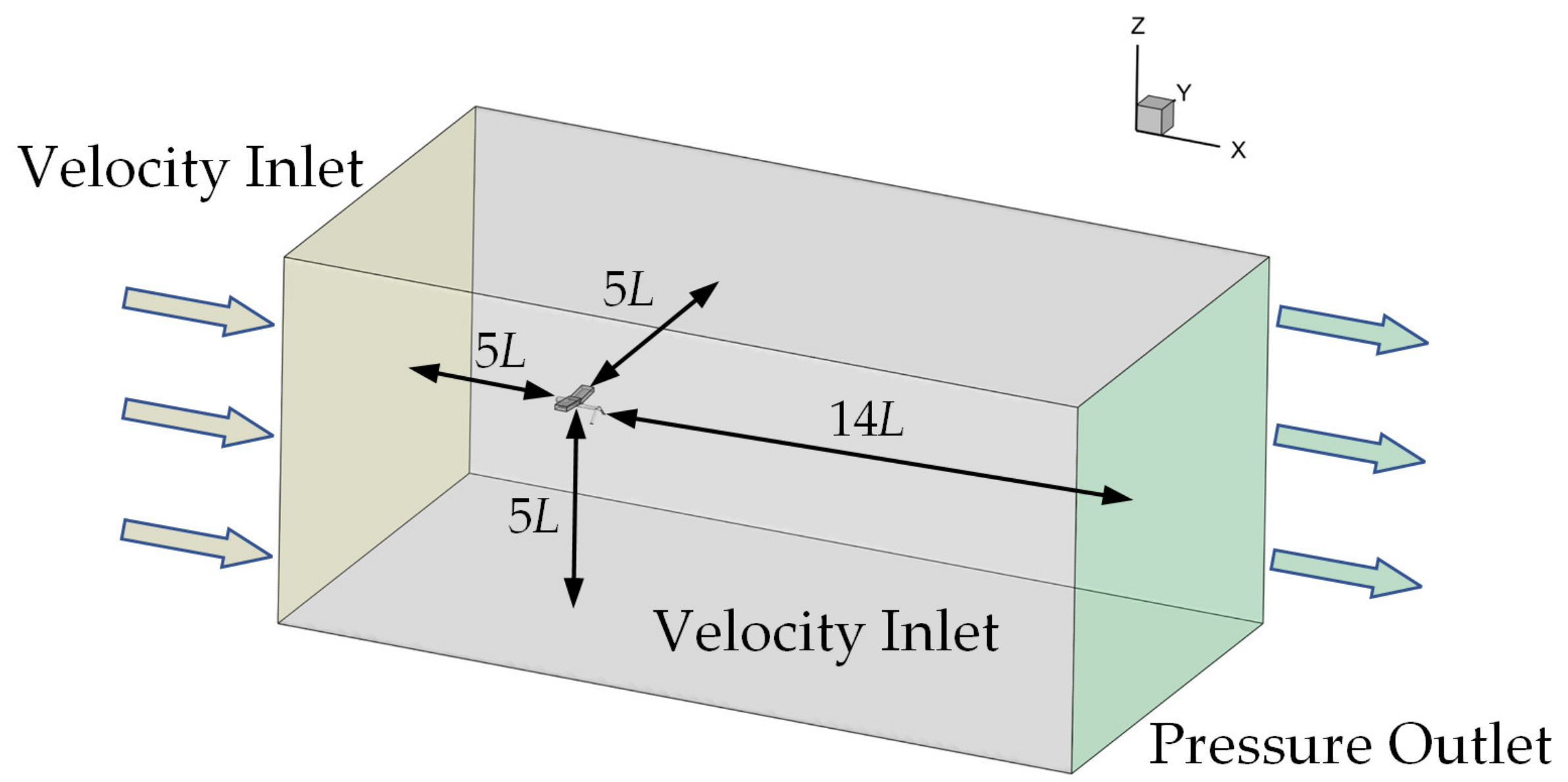
2. Simulation Model
3. Simulation Method
3.1. Flow Solver
3.2. Computational Mesh
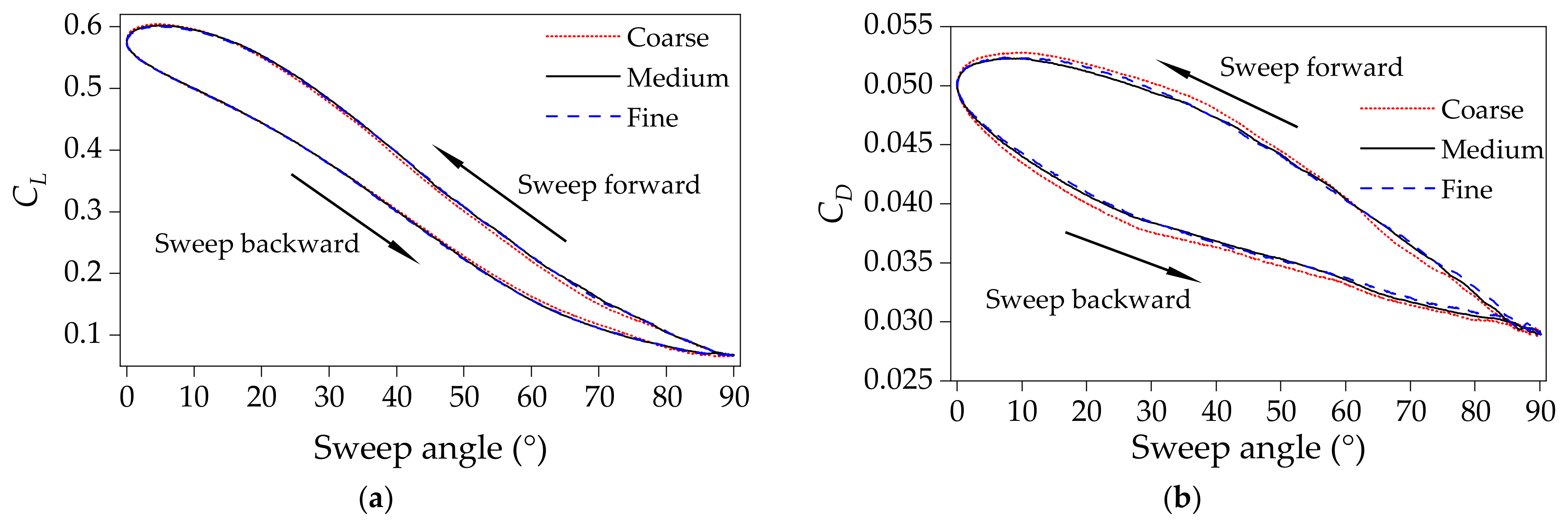
3.3. Mesh Independence
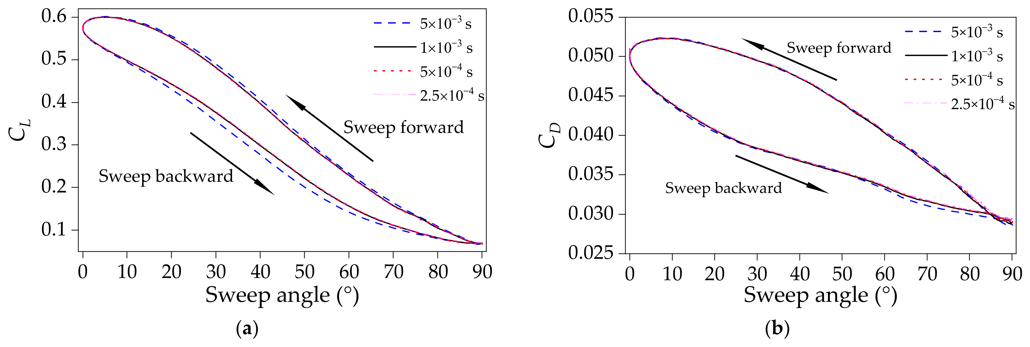
3.4. Time Step Independence
3.5. Power Consumption Models
4. Results and Discussion
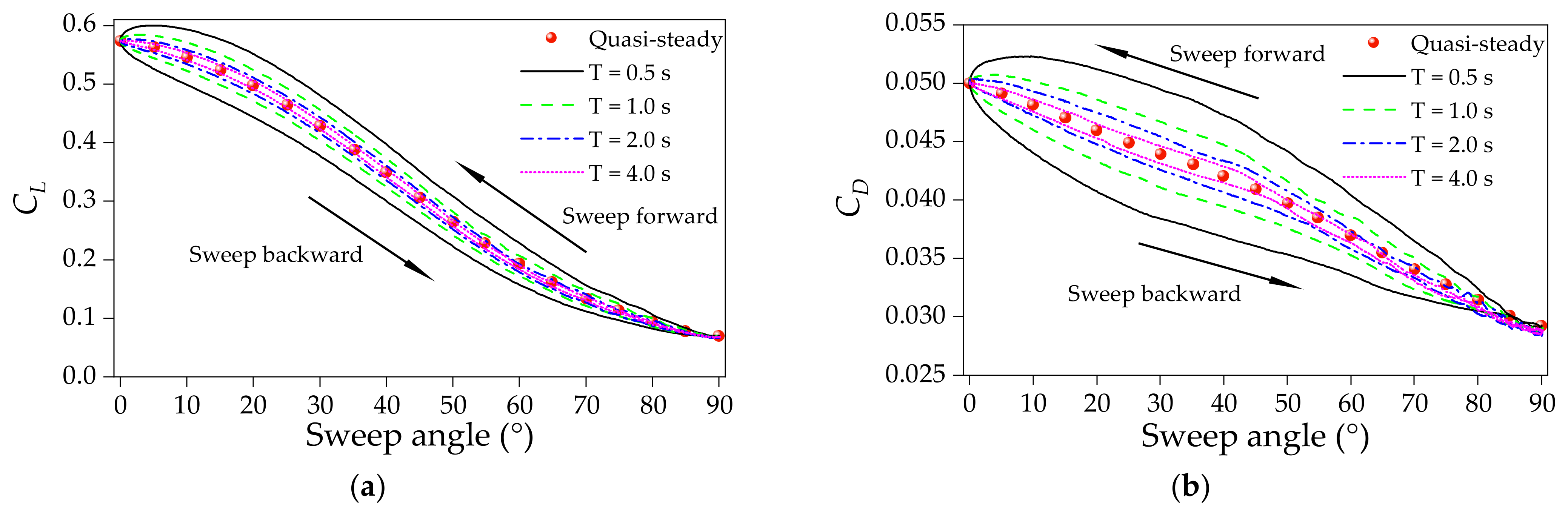
4.1. Transient Aerodynamic Characteristics in the Sweep Morphing
4.2. Mechanism of the Transient Aerodynamic Characteristics
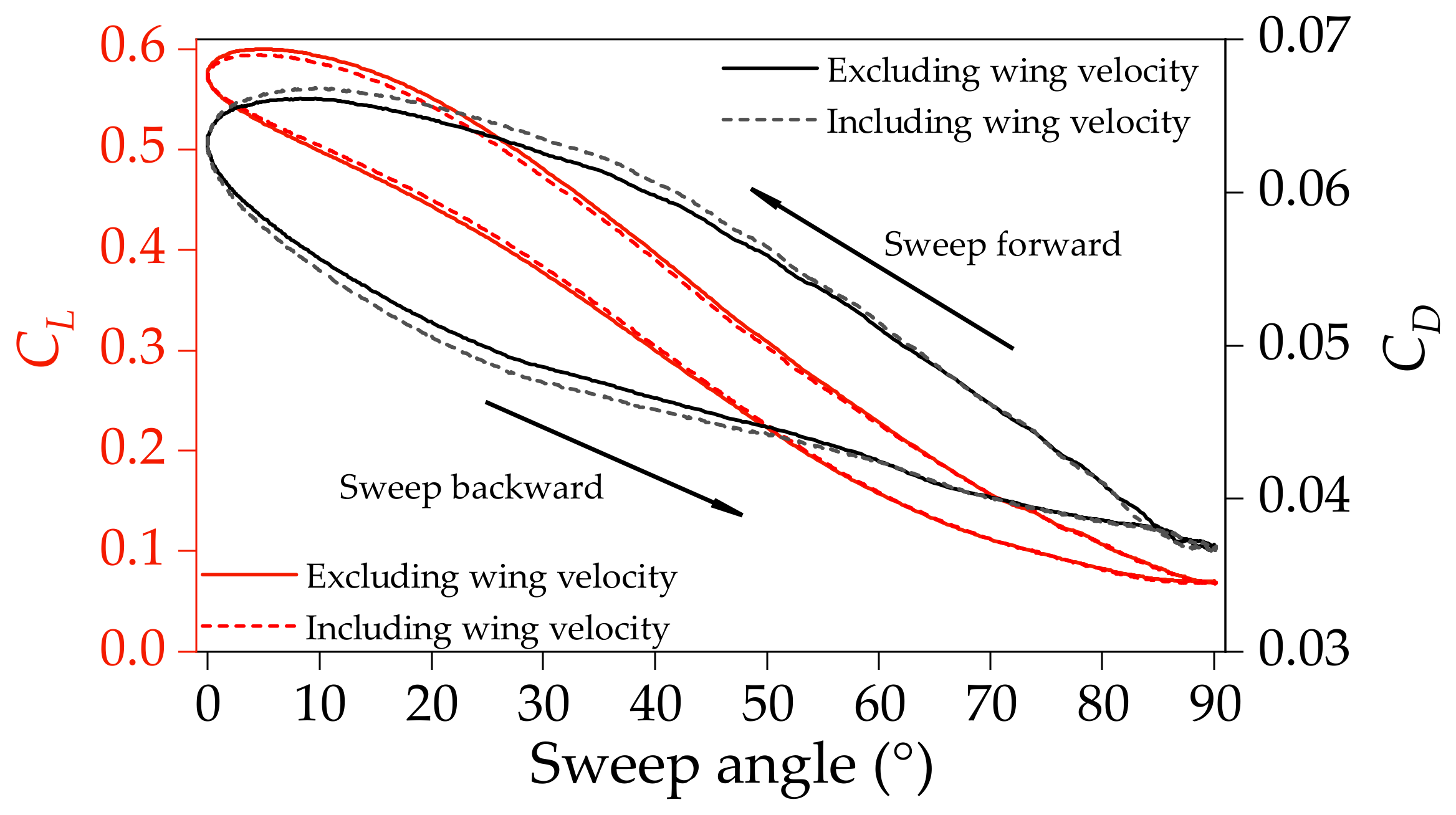
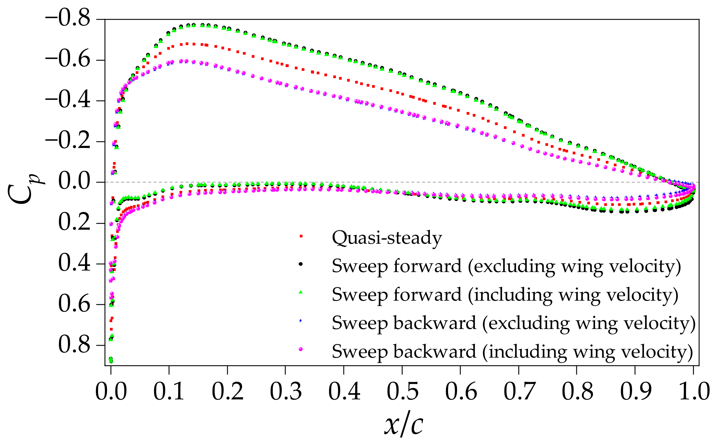
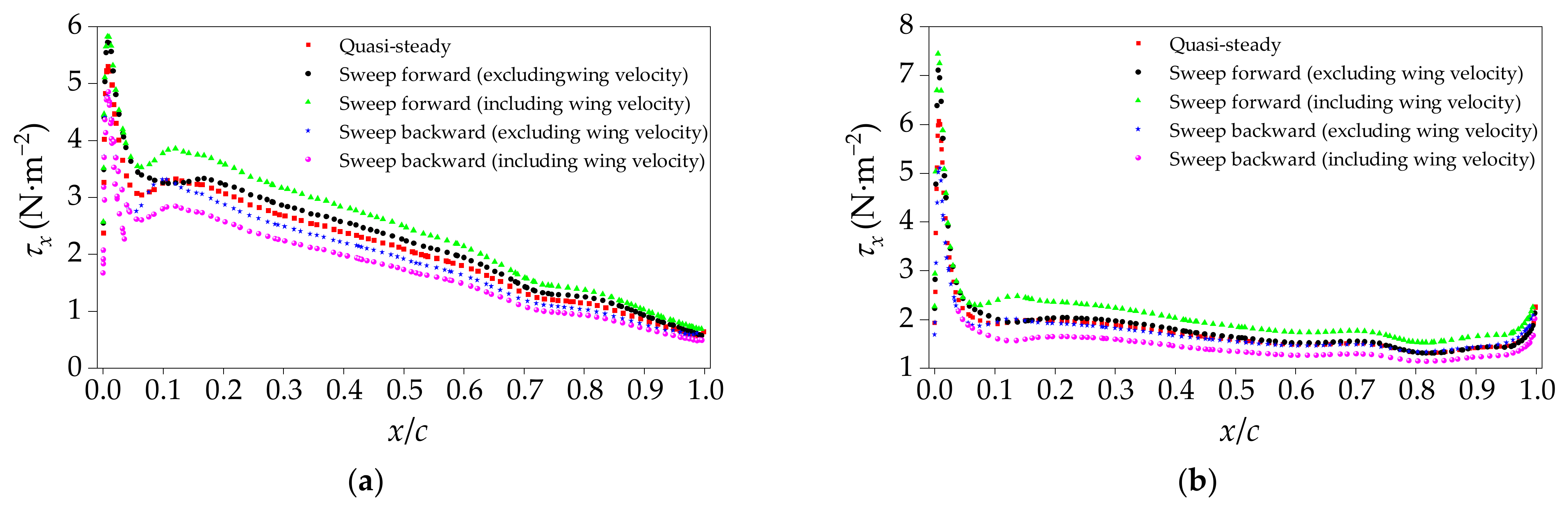
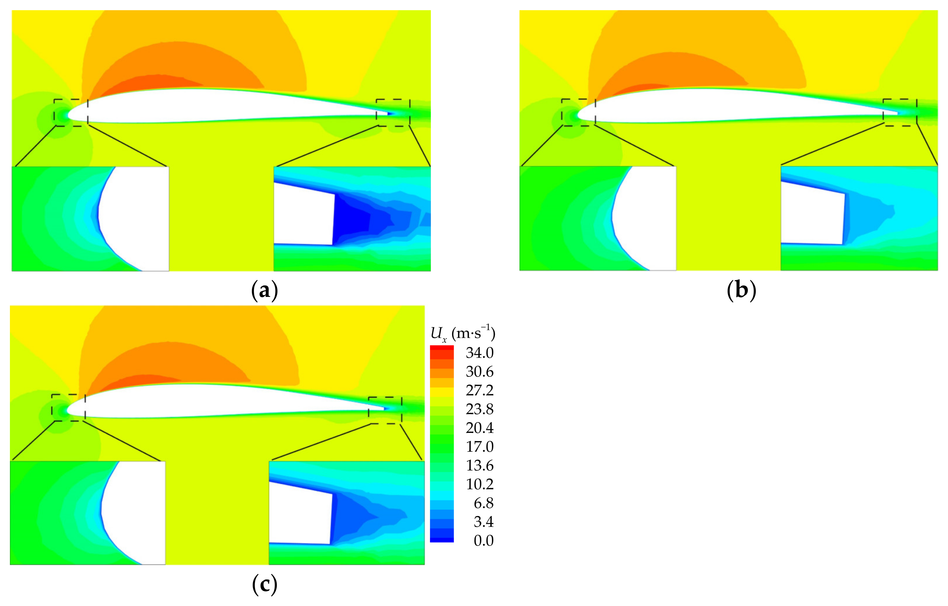
4.2.1. Effect of Additional Velocity Brought by the Wing-Sweep Motion
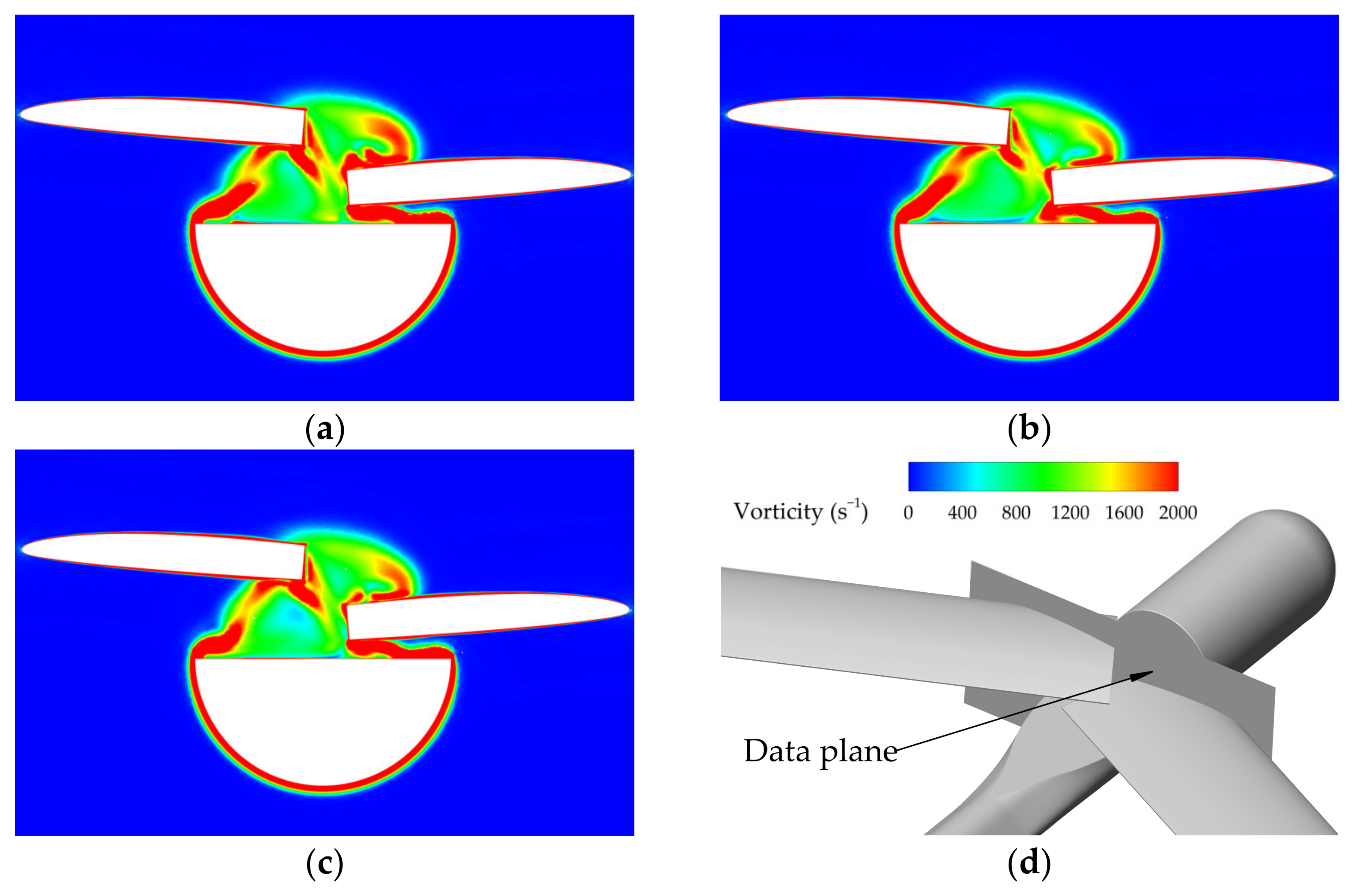
4.2.2. Effect of Flow Structure Hysteresis
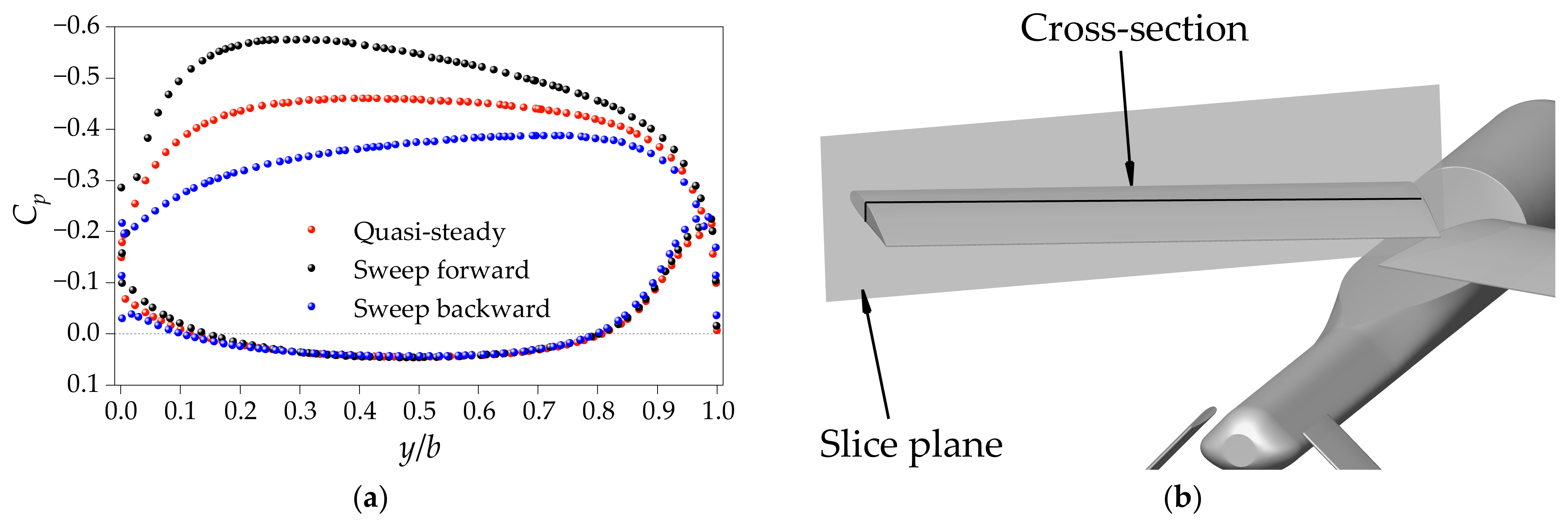
4.3. Longitudinal Stability during the Sweep Morphing Process
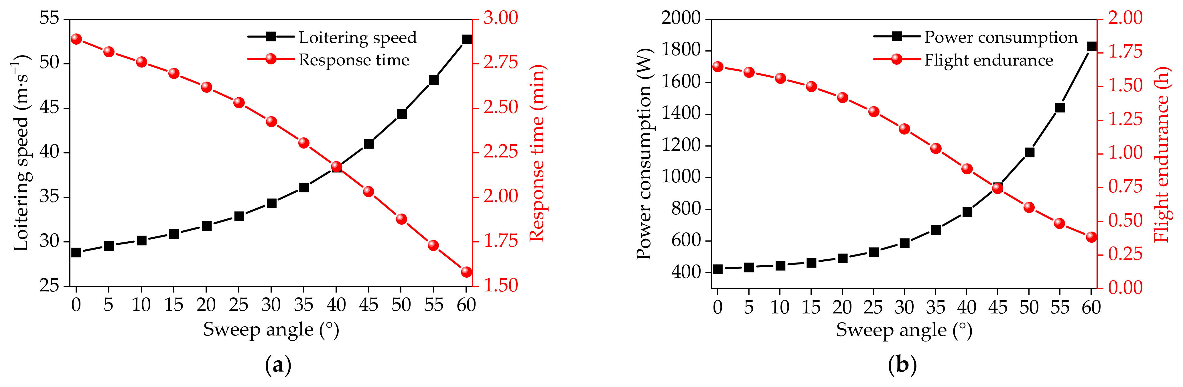
4.4. Flight Performance
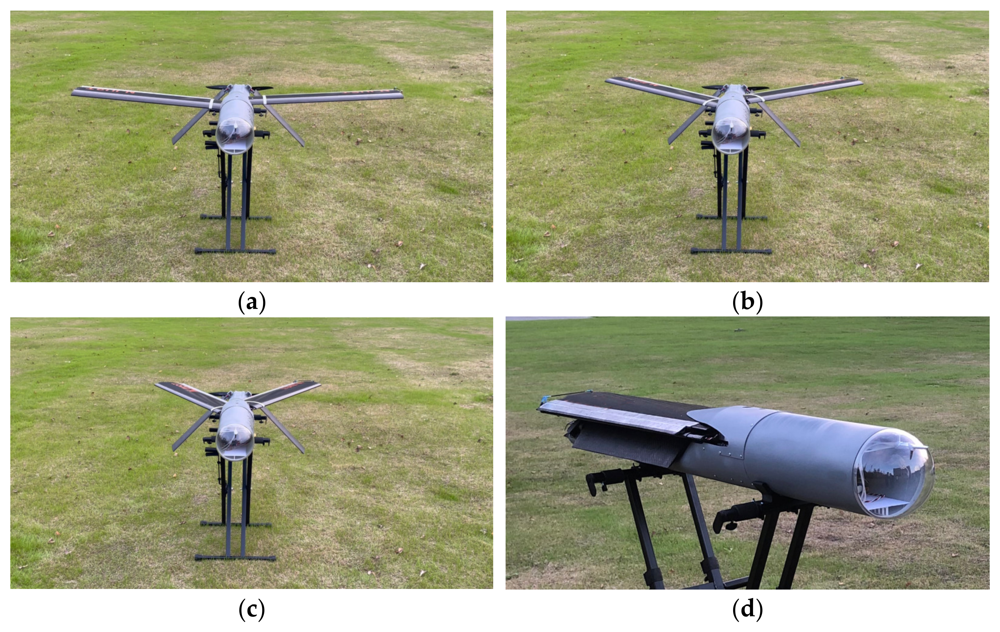
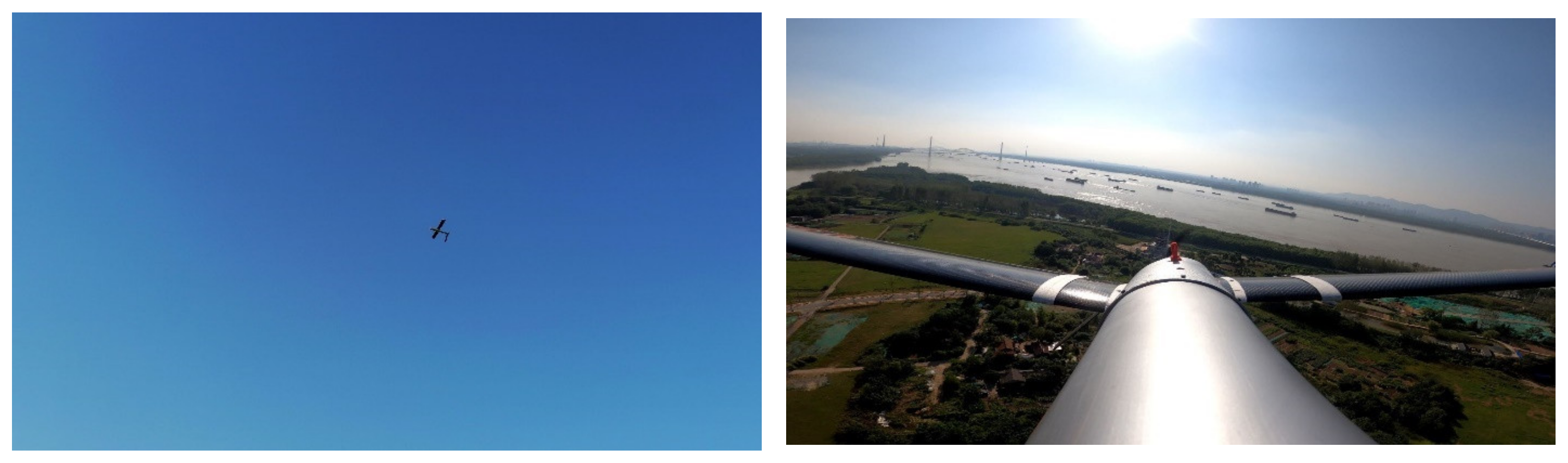
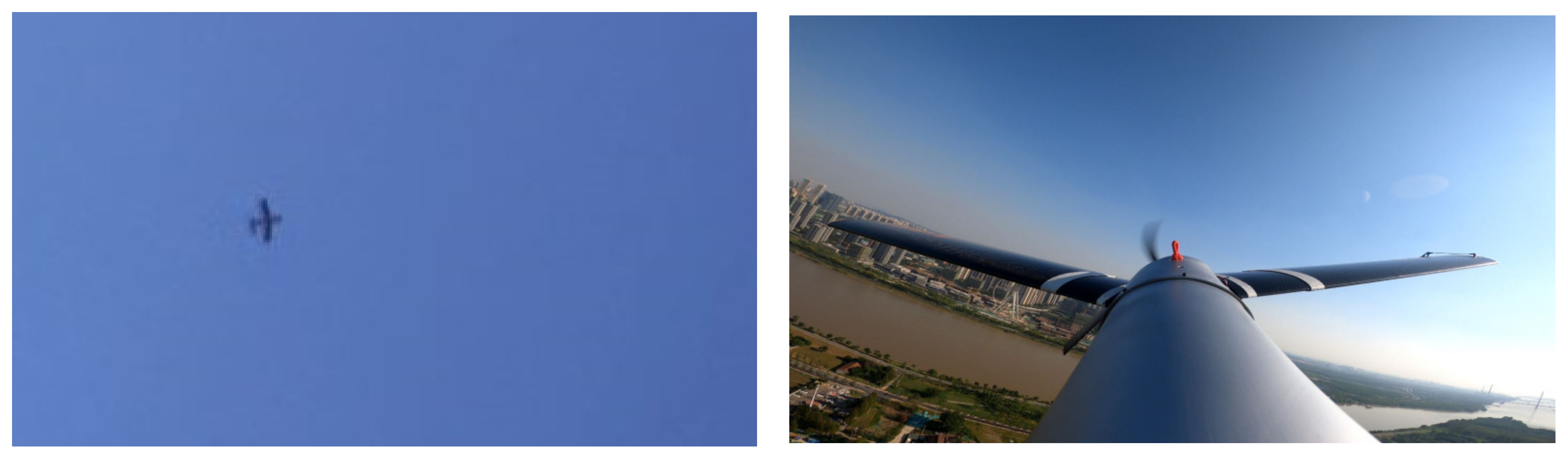
4.5. Flight Test
5. Conclusions
- (1)
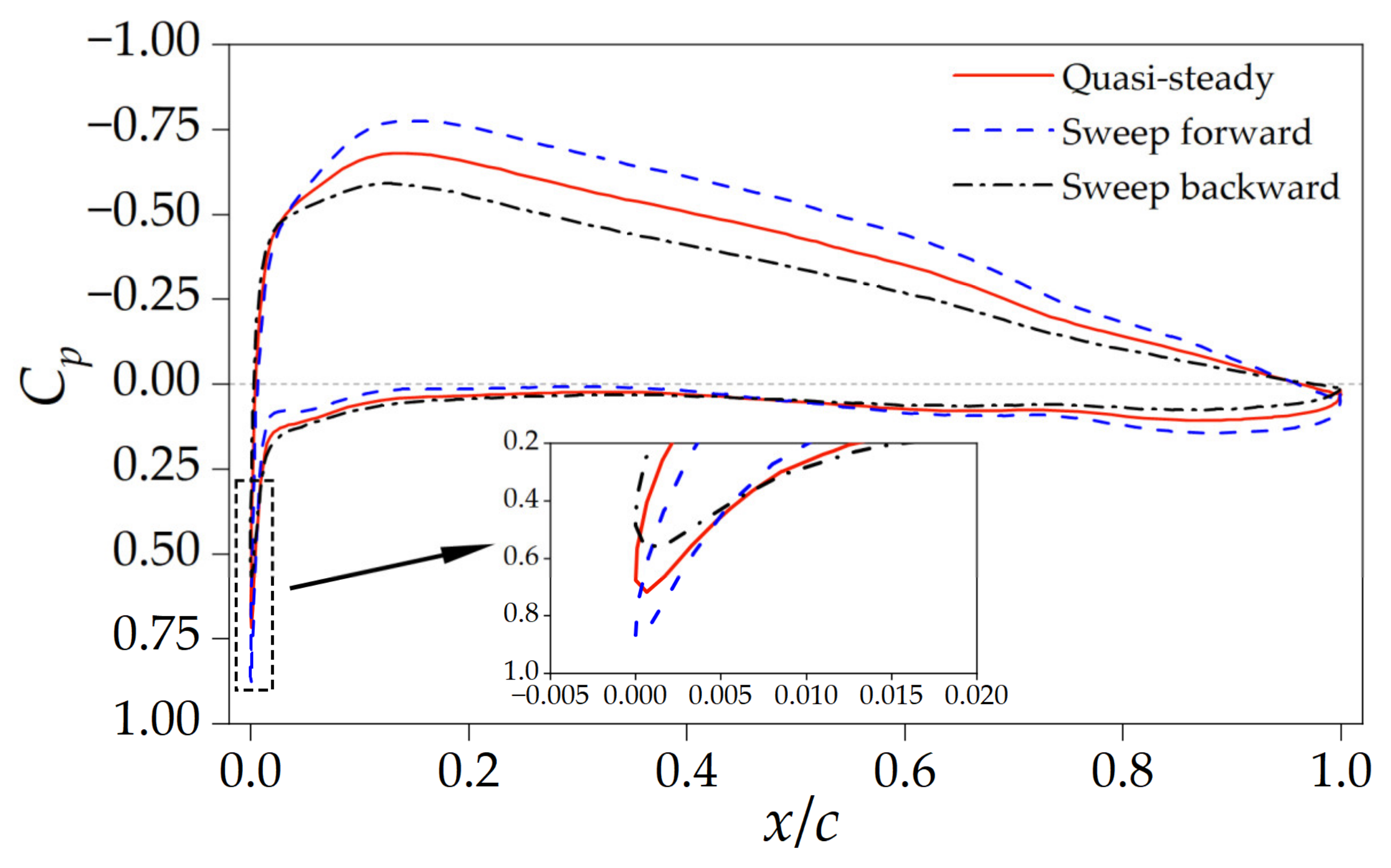
- The transient lift and drag coefficients create dynamic hysteresis loops around the quasi-steady data. Compared with the quasi-steady case, the transient aerodynamic forces are smaller during the sweep-backward process, and larger during the sweep-forward process. The difference between the transient and quasi-steady aerodynamic forces increases with increases in the morphing speed.
- (2)
- The hysteresis effect of the flow structure, rather than the additional velocity resulting from wing-sweep morphing, is the major contributor to the aerodynamic hysteresis loop. During the wing morphing process, the flow structure takes time to match the changing geometry, resulting in a transient pressure distribution which differs from the quasi-steady distribution on the leading edge and upper wing surfaces. This discrepancy between the transient and quasi-steady cases leads to the observed differences in aerodynamic forces.
- (3)
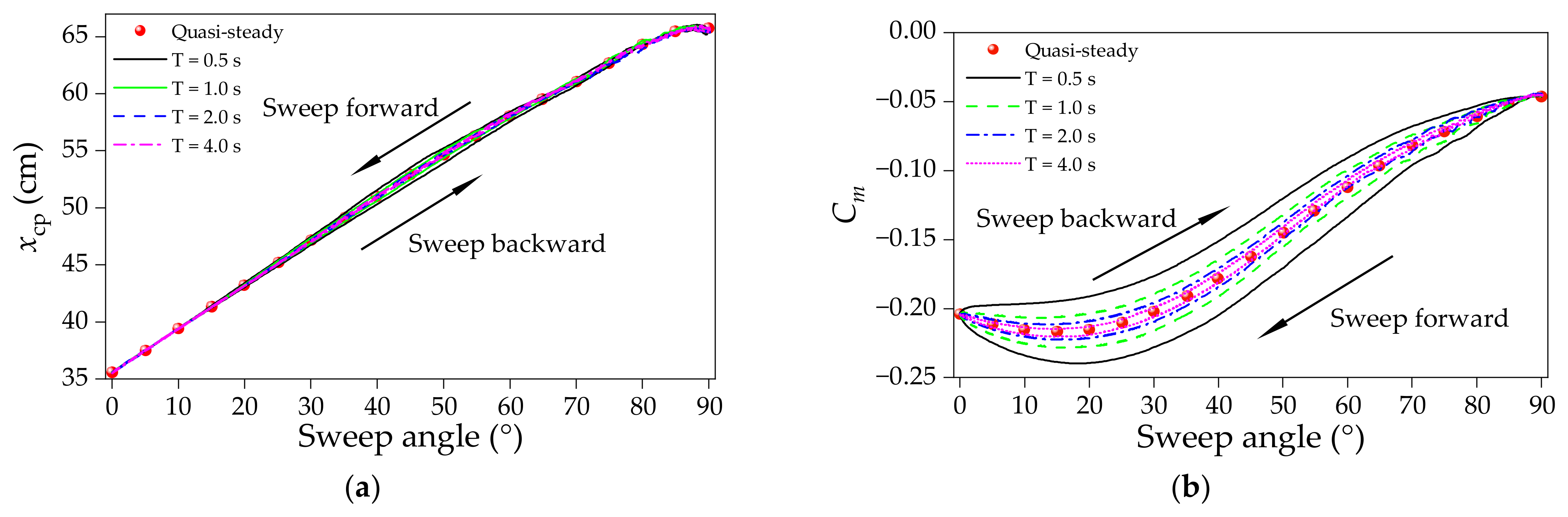
- Similar to the transient aerodynamic forces, the transient pitching moment also creates a dynamic hysteresis loop around the quasi-steady data. However, the sweep morphing process does not affect the linear correlation between the center of pressure and the wing-sweep angle.
- (4)
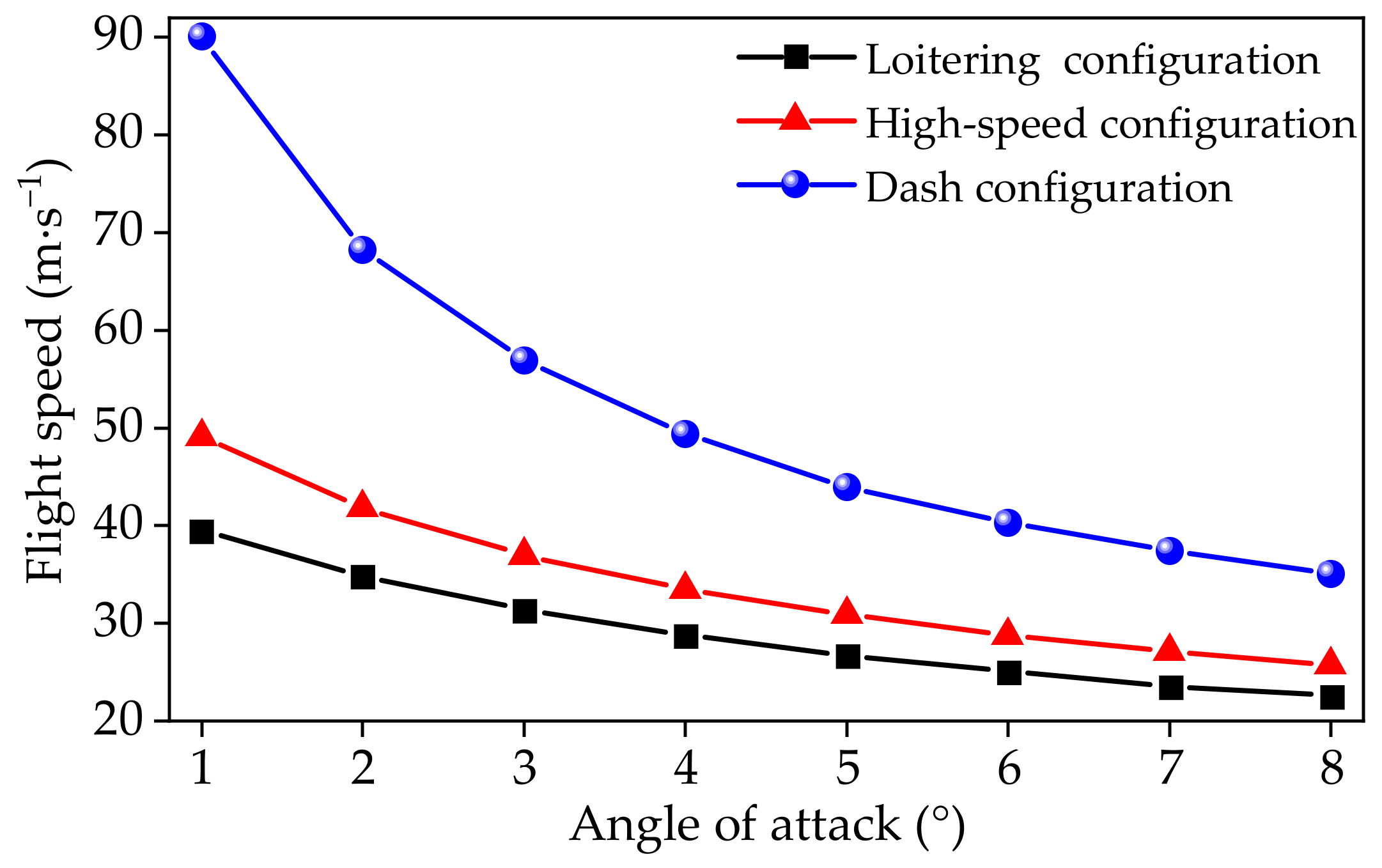
- Flight testing validates the effectiveness of the proposed wing-sweeping concept for expanding the flight speed of tube-launched UAVs. The flight data obtained from flight control system agree well with the numerical data. Compared to conventional tube-launched UAVs, the tube-launched aircraft with a variable-sweep wing exhibits a wider speed range, from 22.59 to 90.12 m/s, and achieves an 82.84% increase in loitering speed.
Author Contributions
Funding
Data Availability Statement
Conflicts of Interest
References
- Zhu, Z.; Guo, H.; Ma, J. Aerodynamic layout optimization design of a barrel-launched UAV wing considering control capability of multiple control surfaces. Aerosp. Sci. Technol. 2019, 93, 105297. [Google Scholar] [CrossRef]
- Yang, X.; Wang, T.; Liang, J.; Yao, G.; Liu, M. Survey on the novel hybrid aquatic–aerial amphibious aircraft: Aquatic unmanned aerial vehicle (AquaUAV). Prog. Aerosp. Sci. 2015, 74, 131–151. [Google Scholar] [CrossRef]
- Zhang, G.Q.; Yu, S.C.M. Unsteady aerodynamics of a morphing tandem-wing unmanned aerial vehicle. J. Aircr. 2012, 49, 1315–1323. [Google Scholar] [CrossRef]
- Negahban, M.H.; Bashir, M.; Traisnel, V.; Botez, R.M. Seamless morphing trailing edge flaps for UAS-S45 using high-fidelity aerodynamic optimization. Chin. J. Aeronaut. 2024, 37, 12–29. [Google Scholar] [CrossRef]
- Papadopoulos, C.; Mitridis, D.; Yakinthos, K. Conceptual design of a novel unmanned ground effect vehicle (UGEV) and flow control integration study. Drones 2022, 6, 25. [Google Scholar] [CrossRef]
- Sicim Demirci, M.S.; Pecora, R.; Kaya, M.O. Design of a large-scale model for wind tunnel test of a multiadaptive flap concept. Chin. J. Aeronaut. 2024, 37, 58–80. [Google Scholar] [CrossRef]
- Billingsley, E.; Ghommem, M.; Vasconcellos, R.; Abdelkefi, A. Role of active morphing in the aerodynamic performance of flapping wings in formation flight. Drones 2021, 5, 90. [Google Scholar] [CrossRef]
- Barroso-Barderas, E.; Rodríguez-Sevillano, Á.A.; Bardera-Mora, R.; Crespo-Moreno, J.; Matías-García, J.C. Design of non-conventional flight control systems for bioinspired micro air vehicles. Drones 2022, 6, 248. [Google Scholar] [CrossRef]
- Dai, P.; Yan, B.; Huang, W.; Zhen, Y.; Wang, M.; Liu, S. Design and aerodynamic performance analysis of a variable-sweep-wing morphing waverider. Aerosp. Sci. Technol. 2020, 98, 105703. [Google Scholar] [CrossRef]
- Li, D.; Zhao, S.; Da Ronch, A.; Xiang, J.; Drofelnik, J.; Li, Y.; Zhang, L.; Wu, Y.; Kintscher, M.; Monner, H.P.; et al. A review of modelling and analysis of morphing wings. Prog. Aerosp. Sci. 2018, 100, 46–62. [Google Scholar] [CrossRef]
- Ozbek, E.; Ekici, S.; Karakoc, T.H. Unleashing the potential of morphing wings: A novel cost effective morphing method for UAV surfaces, rear spar articulated wing camber. Drones 2023, 7, 379. [Google Scholar] [CrossRef]
- Quintana, A.; Graves, G.; Hassanalian, M.; Abdelkefi, A. Aerodynamic analysis and structural integrity for optimal performance of sweeping and spanning morphing unmanned air vehicles. Aerosp. Sci. Technol. 2021, 110, 106458. [Google Scholar] [CrossRef]
- Wu, M.; Shi, Z.; Xiao, T.; Ang, H. Energy optimization and investigation for Z-shaped sun-tracking morphing-wing solar-powered UAV. Aerosp. Sci. Technol. 2019, 91, 1–11. [Google Scholar] [CrossRef]
- Ajanic, E.; Feroskhan, M.; Mintchev, S.; Noca, F.; Floreano, D. Bioinspired wing and tail morphing extends drone flight capabilities. Sci. Robot. 2020, 5, eabc2897. [Google Scholar] [CrossRef] [PubMed]
- Harvey, C.; Gamble, L.L.; Bolander, C.R.; Hunsaker, D.F.; Joo, J.J.; Inman, D.J. A review of avian-inspired morphing for UAV flight control. Prog. Aerosp. Sci. 2022, 132, 100825. [Google Scholar] [CrossRef]
- Liu, B.; Liang, H.; Han, Z.-H.; Yang, G. Surrogate-based aerodynamic shape optimization of a sliding shear variable sweep wing over a wide Mach-number range with plasma constraint relaxation. Struct. Multidiscip. Optim. 2023, 66, 43. [Google Scholar] [CrossRef]
- Li, H.; Chen, W.; Feng, Y.; Deng, J.; Liu, Y. Development of a novel high bandwidth piezo-hydraulic actuator for a miniature variable swept wing. Int. J. Mech. Sci. 2023, 240, 107926. [Google Scholar] [CrossRef]
- Chengyang, L.; Xiaotian, Z.; Ruizhi, L.; Tiandong, X. Proof-of-concept study of flexible lattice variable sweptback wing. AIAA J. 2023, 61, 1129–1141. [Google Scholar] [CrossRef]
- Yang, G.; Guo, H.; Xiao, H.; Liu, R.; Shi, C. Shear-driving force and critical shear angle analysis of kevlar/carbon fiber hybrid composite skins for a shear variable-sweep wing based on the classical plate theory. Appl. Compos. Mater. 2022, 29, 1871–1887. [Google Scholar] [CrossRef]
- Yang, G.; Guo, H.; Xiao, H.; Jiang, H.; Liu, R. Out-of-plane stiffness analysis of kevlar/carbon fiber hybrid composite skins for a shear variable-sweep wing. Appl. Compos. Mater. 2021, 28, 1653–1673. [Google Scholar] [CrossRef]
- Hao, F.; Tang, T.; Gao, Y.; Li, Y.; Yi, S.; Lu, J. Continuous morphing trailing-edge wing concept based on multi-stable nanomaterial. Chin. J. Aeronaut. 2021, 34, 219–231. [Google Scholar] [CrossRef]
- Fazelzadeh, S.A.; Rezaei, M.; Mazidi, A. Aeroelastic analysis of swept pre-twisted wings. J. Fluids Struct. 2020, 95, 103001. [Google Scholar] [CrossRef]
- Mir, I.; Maqsood, A.; Eisa, S.A.; Taha, H.; Akhtar, S. Optimal morphing—Augmented dynamic soaring maneuvers for unmanned air vehicle capable of span and sweep morphologies. Aerosp. Sci. Technol. 2018, 79, 17–36. [Google Scholar] [CrossRef]
- Chakravarthy, A.; Grant, D.T.; Lind, R. Time-varying dynamics of a micro air vehicle with variable-sweep morphing. J. Guid. Control Dyn. 2012, 35, 890–903. [Google Scholar] [CrossRef]
- Yan, B.; Dai, P.; Liu, R.; Xing, M.; Liu, S. Adaptive super-twisting sliding mode control of variable sweep morphing aircraft. Aerosp. Sci. Technol. 2019, 92, 198–210. [Google Scholar] [CrossRef]
- Greatwood, C.; Waldock, A.; Richardson, T. Perched landing manoeuvres with a variable sweep wing UAV. Aerosp. Sci. Technol. 2017, 71, 510–520. [Google Scholar] [CrossRef]
- Jiang, W.; Dong, C.; Wang, Q. A systematic method of smooth switching LPV controllers design for a morphing aircraft. Chin. J. Aeronaut. 2015, 28, 1640–1649. [Google Scholar] [CrossRef]
- Gao, L.; Zhu, Y.; Zang, X.; Zhang, J.; Chen, B.; Li, L.; Zhao, J. Dynamic analysis and experiment of multiple variable sweep wings on a tandem-wing MAV. Drones 2023, 7, 552. [Google Scholar] [CrossRef]
- Yan, B.; Li, Y.; Dai, P.; Liu, S. Aerodynamic analysis, dynamic modeling, and control of a morphing aircraft. J. Aerosp. Eng. 2019, 32, 04019058. [Google Scholar] [CrossRef]
- Bai, P.; Liu, X.; Chen, Q.; Li, F. Study on dynamic hysteresis and linear modeling of the sliding-skin variable-sweep morphing wing aerodynamics. In Proceedings of the 23rd International Congress of Theoretical and Applied Mechanics, Beijing, China, 19 August 2012. [Google Scholar]
- Han, H.; Hu, J.; Yu, Y. Investigation of the unsteady aerodynamic characteristics of an unmanned aerial vehicle with variable-sweep morphing. In Proceedings of the 32nd AIAA Applied Aerodynamics Conference, Atlanta, GA, USA, 16 June 2014. [Google Scholar]
- Zeng, L.; Liu, L.; Shao, X.; Li, J. Mechanism analysis of hysteretic aerodynamic characteristics on variable-sweep wings. Chin. J. Aeronaut. 2023, 36, 212–222. [Google Scholar] [CrossRef]
- Wang, Y.; He, X.; He, G.; Wang, Q.; Chen, L.; Liu, X. Aerodynamic performance of the flexibility of corrugated dragonfly wings in flapping flight. Acta Mech. Sin. 2022, 38, 322038. [Google Scholar] [CrossRef]
- Zhu, Z.; Song, B.; Xue, D.; Yang, W.; Lang, X.; Yang, X. Three-dimensional sweeping motion effects on hovering dragonflies. Aerosp. Sci. Technol. 2022, 127, 107701. [Google Scholar] [CrossRef]
- Zheng, Y.; Qu, Q.; Liu, P.; Wen, X.; Zhang, Z. Numerical analysis of the porpoising motion of a blended wing body aircraft during ditching. Aerosp. Sci. Technol. 2021, 119, 107131. [Google Scholar] [CrossRef]
- Kljuno, E.; Catovic, A. A generalized model for estimation of aerodynamic forces and moments for irregularly shaped bodies. Def. Technol. 2019, 15, 369–389. [Google Scholar] [CrossRef]
- Zhang, Z.; Li, D.; Zhou, J.; Pan, W.; Xu, Z.; Cai, J. Numerical simulation of wake vortex for the flight near the ground with different boundary conditions. Eng. Appl. Comput. Fluid Mech. 2022, 16, 484–500. [Google Scholar] [CrossRef]
- Wang, P.; Liu, Q.; Li, C.; Miao, W.; Yue, M.; Xu, Z. Investigation of the aerodynamic characteristics of horizontal axis wind turbine using an active flow control method via boundary layer suction. Renew. Energy 2022, 198, 1032–1048. [Google Scholar] [CrossRef]
- Zhang, Y.; Yan, C.; Chen, H.; Yin, Y. Study of riblet drag reduction for an infinite span wing with different sweep angles. Chin. J. Aeronaut. 2020, 33, 3125–3137. [Google Scholar] [CrossRef]
- Chen, F.; Yu, J.; Shen, Y.; Ma, A. Dynamic analysis of wing unfolding of tube-launched tandem-wing unmanned aerial vehicle. Acta Armamentarii 2019, 40, 89–98. [Google Scholar]
- Si, P.; Wu, M.; Huo, Y.; Wu, Z. Investigation on improving aerodynamics and flight performance for an unmanned aircraft with a span-extendable wing. Aerosp. Sci. Technol. 2024, 145, 108905. [Google Scholar] [CrossRef]


| Parameter | Symbol | Value |
|---|---|---|
| Mass (kg) | m | 10 |
| Fuselage length (m) | L | 1.15 |
| Battery capacity (Wh) | Eb | 700 |
| Configuration | Loitering | High-Speed | Dash |
|---|---|---|---|
| Sweep angle (°) | 0 | 30 | 60 |
| Wingspan (m) | 1.4 | 1.21 | 0.7 |
| Wing area (m2) | 0.28 | 0.2569 | 0.2107 |
| Aspect ratio | 7 | 5.7 | 2.3 |
| Data | Loitering Wing | High-Speed Wing |
|---|---|---|
| Flight speed (m/s) | 29.11 | 35.61 |
| Power consumption (W) | 430 | 605.55 |
| Flight endurance (h) | 1.61 | 1.10 |
| Error in flight speed | 0.93% | 3.51% |
| Error in power consumption | 1.27% | 2.63% |
| Error in flight endurance | 2.48% | 7.91% |
Disclaimer/Publisher’s Note: The statements, opinions and data contained in all publications are solely those of the individual author(s) and contributor(s) and not of MDPI and/or the editor(s). MDPI and/or the editor(s) disclaim responsibility for any injury to people or property resulting from any ideas, methods, instructions or products referred to in the content. |
© 2024 by the authors. Licensee MDPI, Basel, Switzerland. This article is an open access article distributed under the terms and conditions of the Creative Commons Attribution (CC BY) license (https://creativecommons.org/licenses/by/4.0/).
Share and Cite
Si, P.; Wu, M.; Huo, Y.; Wu, Z. Investigation of a Tube-Launched Unmanned Aerial Vehicle with a Variable-Sweep Wing. Drones 2024, 8, 474. https://doi.org/10.3390/drones8090474
Si P, Wu M, Huo Y, Wu Z. Investigation of a Tube-Launched Unmanned Aerial Vehicle with a Variable-Sweep Wing. Drones. 2024; 8(9):474. https://doi.org/10.3390/drones8090474
Chicago/Turabian StyleSi, Peng, Mingjian Wu, Yongqing Huo, and Zhilin Wu. 2024. "Investigation of a Tube-Launched Unmanned Aerial Vehicle with a Variable-Sweep Wing" Drones 8, no. 9: 474. https://doi.org/10.3390/drones8090474