Article

Investigation of a Tube-Launched Unmanned Aerial Vehicle with a Variable-Sweep Wing

1
School of Mechanical Engineering, Nanjing University of Science and Technology, Nanjing 210094, China
2
Ammunition Technology Center, Chongqing Jialing Special Equipment Co., Ltd., Chongqing 400032, China
*
Authors to whom correspondence should be addressed.
Drones 2024, 8(9), 474; https://doi.org/10.3390/drones8090474
Submission received: 23 July 2024 / Revised: 31 August 2024 / Accepted: 4 September 2024 / Published: 10 September 2024

Abstract

:
Foldable wings are designed for tube-launched unmanned aerial vehicles (UAVs), aiming to improve portability and meet launch platform requirements. However, conventional tube-launched UAVs cannot operate across the wide speed ranges required for the performance of multiple missions, due to the fixed configuration of their wings after launch. This study therefore proposes a tube-launched UAV which can change wing-sweep angle to expand the flight speed range and enhance the UAV’s agility. A computational aerodynamics method is employed to assess the transient aerodynamic performance of the UAV during the sweep morphing process. The simulation results indicate that the transient aerodynamic forces generate a dynamic hysteresis loop around the quasi-steady data. The lift and drag coefficients exhibit maximum relative deviations of 18.5% and 12.7% from the quasi-steady data for the sweep morphing period of 0.5 s. The hysteresis effect of the flow structure, rather than the additional velocity resulting from wing-sweep morphing, is the major contributor to the aerodynamic hysteresis loop. Compared to the conventional tube-launched UAVs, the proposed tube-launched UAV with a variable-sweep wing shows a wider flight speed range, from 22.59 to 90.12 m/s, and achieves an 82.84% increase in loitering speed. To verify the effectiveness of the wing-sweeping concept, a prototype was developed, and a flight test was carried out. The test data obtained from flight control system agree well with the simulation data, which demonstrates the feasibility and effectiveness of the variable-sweep wing in widening the speed range for tube-launched UAVs. This work can provide a reference for the design of tube-launched UAVs for wide speed range flight.

1. Introduction

Tube-launched unmanned aerial vehicles (UAVs) with foldable wings have emerged as a new type of unmanned aircraft capable of performing extended reconnaissance and precise delivery tasks [1]. These enhancements significantly improve the situational awareness for operators in complex environments and have attracted considerable attention in recent years. Tube-launched UAVs, such as the Switchblade, Hero, and Coyote, have been utilized in various applications [1,2,3], improving portability and adaptability across various platforms. Tube-launched UAVs initially remain cylindrical by means of wing folding and can be launched from tubes. Upon launch, the wings are deployed using a torsion spring-driven mechanism. Compared to fixed-wing UAVs, tube-launched UAVs are smaller and easier to deploy. However, the configurations of tube-launched UAVs are fixed after launch, resulting in limited flight speed and maneuverability. Conventional tube-launched UAVs cannot operate across the wide speed ranges required for the performance of multiple missions.
Morphing wings can adjust the wing airfoil [4,5,6,7,8] and planform [9,10,11,12,13] to achieve better flight performance under various flight conditions. The wing-sweep morphing can effectively extend drone flight capabilities [14]. Historically, a particular focus of sweep morphing has been the design of supersonic fighter aircraft. Implementing variable-sweep mechanisms in large-scale aircraft has led to systems of increased weight and complexity. However, with advancements in aerospace materials and the demand for multi-role platforms, research on sweep morphing has regained popularity, particularly in reference to the unmanned aerial vehicle, due to the lightweight mechanism and cost-effectiveness of the wing-sweep technology. Many studies on low-subsonic variable-sweep unmanned aerial vehicles have been conducted, seeking to enhance the overall flight performance and meet multitask requirements [10,14,15]. Considering the advantages of the wing-sweep morphing concept, this study proposes a tube-launched UAV with a variable-sweep wing in order to address the limitation that existing tube-launched UAVs cannot adapt their configurations to various flight missions.
Recent years have witnessed a growing interest in the sweep morphing wing, including studies on aerodynamic performance [16], structural design [17,18,19,20,21], dynamic modeling [22,23,24], and control [25,26,27,28]. Among the research areas, the analysis of aerodynamic performance serves as the baseline analysis. Previous studies [9,12,25,29] mainly focused on investigating the quasi-steady aerodynamic characteristics of several specific sweep angles. However, the wing-sweep angle changes dynamically under certain flight conditions, such as during rapid unfolding of the wing after launch, and when sweeping back to track moving targets on the ground.
During the wing-sweep morphing process, the aerodynamic characteristics become transient and dynamic [30,31,32]. Significant differences occur between the transient and the quasi-steady aerodynamic characteristics throughout rapid wing morphing. Bai et al. [30] performed wind-tunnel tests to investigate the transient aerodynamic performance of a wing-sweeping UAV. The results indicate that the transient aerodynamic force and moment create a dynamic hysteresis loop around the quasi-steady data. Zeng et al. [32] performed a numerical investigation on the transient aerodynamic performance of a typical wing-sweeping UAV and analyzed the related mechanism. However, the major factors that contribute to the difference between the transient and quasi-steady aerodynamic characteristics have rarely been deeply investigated. In this study, a transient numerical analysis is performed on a tube-launched UAV designed with a variable-sweep wing, and the mechanisms of the transient aerodynamic characteristics are investigated. To study the feasibility and effectiveness of the proposed wing-sweeping concept in improving flight performance, a tube-launched UAV prototype is developed, and a flight test is carried out.
The rest of this paper is organized as follows. Section 2 proposes a design for a tube-launched unmanned aerial vehicle with a variable-sweep wing. Section 3 introduces the simulation’s approach. The transient aerodynamic characteristics and the flight test of the tube-launched aircraft are discussed in Section 4, and then several conclusions are drawn in Section 5.

2. Simulation Model

To expand the flight speed range in order to enable the performance of multiple missions, a tube-launched unmanned aerial vehicle with a variable-sweep wing was developed, as illustrated in Figure 1. MH139F airfoil is used for the wing, and NACA0010 airfoil is adapted for the tail. The UAV is designed with a tube-type fuselage and a deployable configuration. The wing can change sweep angle continuously using a worm gear mechanism. The aileron and the inverted V-tail serve as control surfaces. For better control, an all-moving inverted V-tail is implemented. Foldable propellers are developed to reduce the overall length.
The tube-launched unmanned aerial vehicle with a variable-sweep wing includes four main configurations: loitering configuration with a 0° swept-back angle, as displayed in Figure 1a; high-speed configuration with a 30° swept-back angle, as shown in Figure 1b; dash configuration with a 60° swept-back angle, as rendered in Figure 1c; and a folded configuration, as shown in Figure 1d. The loitering configuration in Figure 1a allows for low-speed, long-endurance loitering above target areas. The sweeping configurations in Figure 1b,c are used for high-speed, high-maneuverability operations aiming to track and capture moving targets on the ground. The folded configuration can be stored in a tube for deployment by ground and air vehicles. Detailed parameters are presented in Table 1 and Table 2.
The wing-sweep morphing motion follows a sinusoidal function,
δ = δ 1 + δ 2 2 + δ 2 δ 1 2 sin ( 2 π T t π 2 )
where t is the time, δ is the sweep angle at time t, δ1 and δ2 are the minimum and maximum sweep angles, respectively, and T is the sweep morphing period.

3. Simulation Method

3.1. Flow Solver

To evaluate the transient aerodynamic performance of the tube-launched aircraft with a variable-sweep wing, the flow solver ANSYS FLUENT 2020R2 is used. The Reynolds number of the freestream, based on the airfoil chord, is 3.4 × 10⁵, and the Mach number is 0.0735. The transient incompressible RANS equations [33,34,35,36] and k-omega shear stress transport turbulence model [37,38] are used to solve for the flow field of the UAV during the morphing process. A steady solver is employed for the flow field of the UAV in static configurations. A pressure-based coupled algorithm with a second-order upwind scheme for spatial discretization is employed. The bounded second-order implicit scheme is used for the transient term.

3.2. Computational Mesh

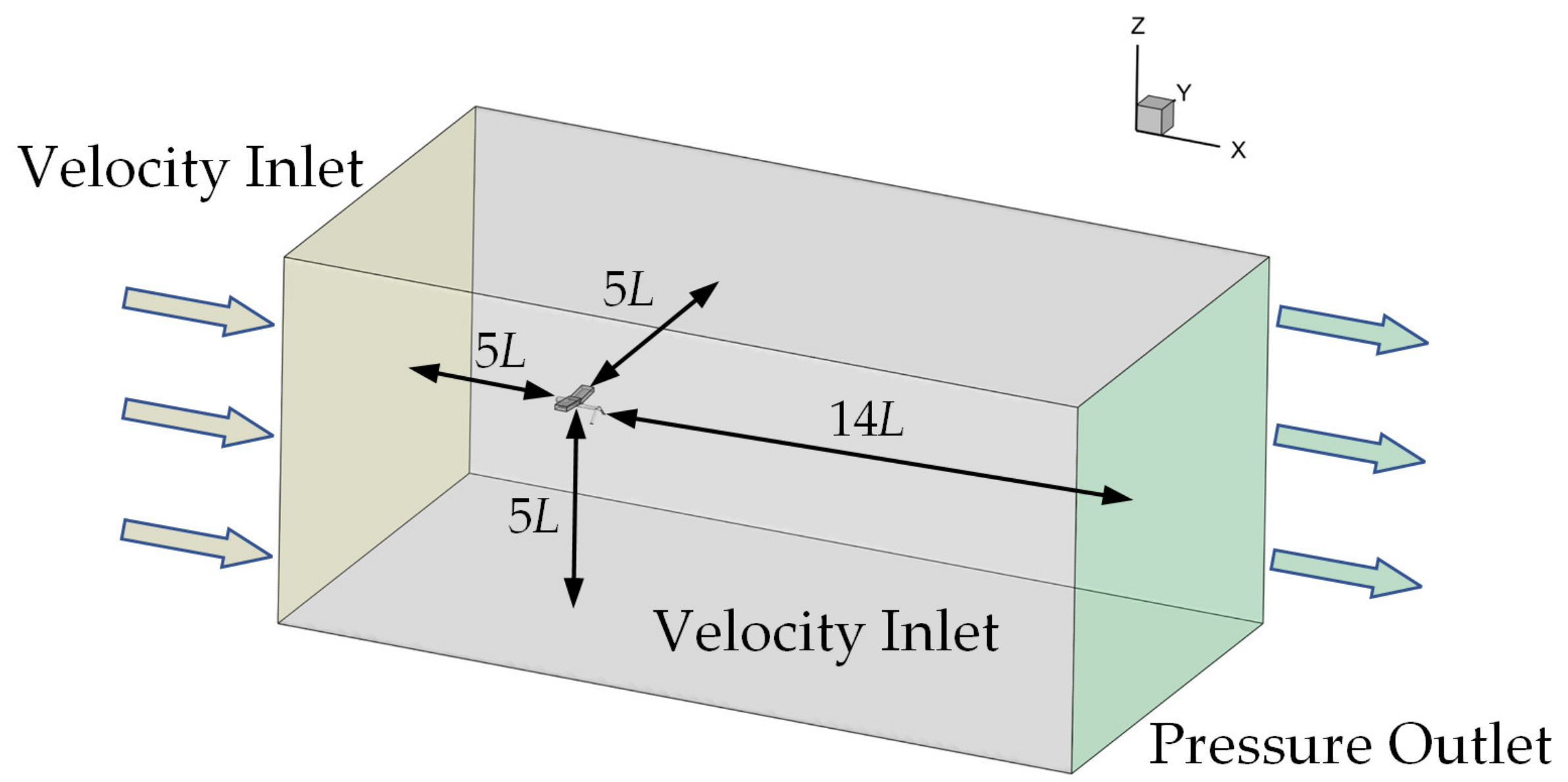
The wing of the UAV undergoes periodic rotations and experiences significant shape changes. To change the wing-sweep angle and ensure the quality of the boundary layer mesh, the dynamic overset mesh method [38] and User-Defined Functions are adopted in the numerical simulation. Absolute velocity formulation is used in the calculations. The mesh sizes for the wing, tail, and fuselage are 2, 3, and 4 mm, respectively. The first grid height normal to the aircraft surface is 0.01 mm, with a growth rate of 1.1 used to ensure a y+ value of the order of 1 [39]. The overset meshes consist of two component meshes for wings and one background mesh for fuselage, as displayed in Figure 2. This treatment can also be found in [32,40]. The aircraft model is placed 5L away from the inlet and 14L from the outlet of the computational domain, as illustrated in Figure 3. The velocity inlet condition is implemented at both the inlet and the lateral boundaries. A no-slip wall condition is applied to the UAV body.

3.3. Mesh Independence

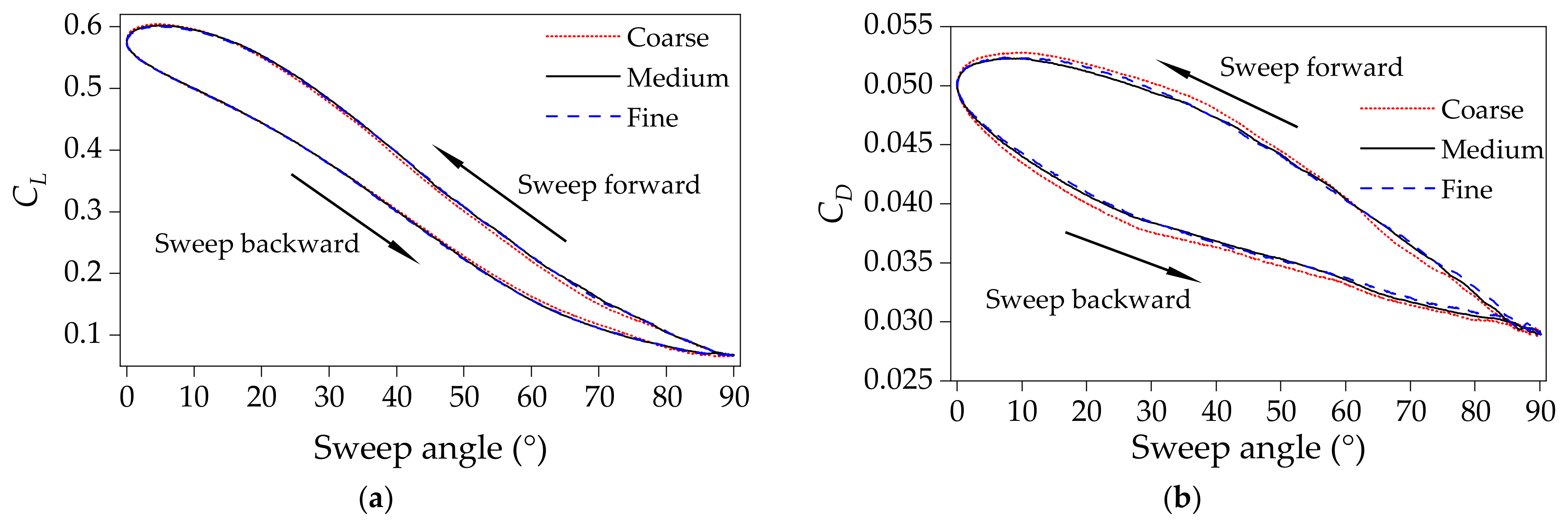
An adequate mesh is required to resolve important flow features, and the mesh is refined in regions of complex flow, particularly within the boundary layers and wake-flow areas near the wing. Three mesh resolutions were evaluated and compared, including a coarse mesh (4.42 million cells), a medium mesh (9.54 million cells), and a fine mesh (12.16 million cells). Compared to the coarse mesh, the results obtained with the medium mesh agree well with those from the fine mesh, as shown in Figure 4. To reduce the calculation time, the medium mesh size is selected.

3.4. Time Step Independence

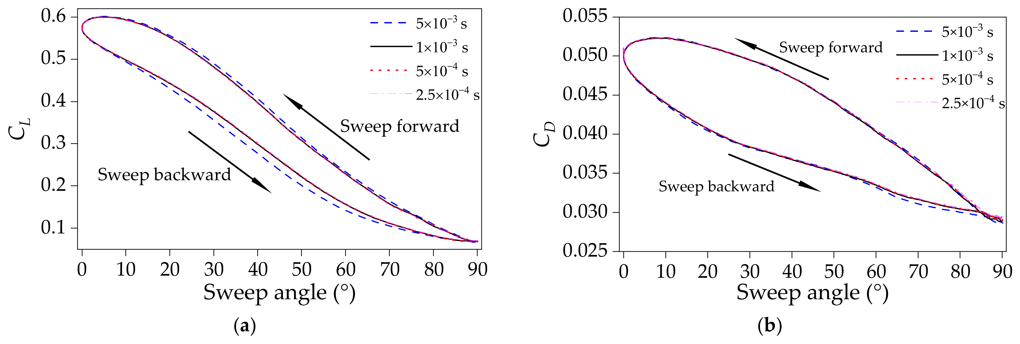
The time step is important in transient simulation. To ensure the numerical stability and accelerate convergence, the flow Courant number is set to 10 due to the use of a coupled implicit algorithm. A sweep morphing period of 0.5 s is used to verify time step independence. Consequently, the time step should be approximately 8 × 10⁻⁴ s. During the numerical simulation, four transient time steps, each with 20 iterations, are tested, as shown in Figure 5. Compared to the time step of 5 × 10⁻³ s, the results for the time steps of 1 × 10⁻³ s, 5 × 10⁻⁴ s, and 2.5 × 10⁻⁴ s are nearly identical. For the time step of 5 × 10⁻⁴ s, the Courant number in most areas is within 1 and the residuals of each equation are below 1 × 10⁻⁷ in each time step. To reduce calculation time, the time step of 5 × 10⁻⁴ s is chosen. The simulations were performed on a Linux cluster with three nodes each equipped with an Intel Xeon Platinum 8375C CPU, taking approximately 51 h per simulation.

3.5. Power Consumption Models

In loitering flight, the lift force on the tube-launched aircraft equals its weight, and the flight speed is
v = 2 m g ρ S C L
where m is the aircraft mass, CL is the lift coefficient, ρ is the air density, and g is the gravity acceleration. The wing reference area used for the aerodynamic coefficients throughout the calculations is fixed at 0.28 m2, corresponding to the wing area of the loitering configuration.
Based on the drag from simulation, the power consumption of the tube-launched UAV can be calculated with
P = 1 η C D C L 3 / 2 2 ρ ( m g ) 3 S
where CD is the drag coefficient, and S is the wing area. η is efficiency from batteries to propeller thrust ( η = η bd η mc η mo η pr ), which can be seen in [41].

4. Results and Discussion

4.1. Transient Aerodynamic Characteristics in the Sweep Morphing

Transient aerodynamic characteristics of the tube-launched aircraft during the sweep morphing process were studied numerically. The wing-sweep angle is sinusoidally adjusted between 0° and 90°, and four different periods are chosen, including T = 0.5, 1.0, 2.0, and 4.0 s. The freestream velocity is 25 m/s, and the angle of attack is 4°. The transient lift coefficient and drag coefficient during the sweep morphing process are shown in Figure 6. For comparison, the corresponding quasi-steady data with the sweep angle varying from 0° to 90° at an interval of 5° are depicted. Results indicate that the transient aerodynamic performance shows a remarkably unsteady dynamic behavior. Both the transient lift and drag coefficients deviate from the quasi-steady data and create a counterclockwise dynamic hysteresis loop. This loop becomes larger with increases in the morphing speed. The transient lift and drag are smaller than the quasi-steady values during the wing sweep-backward process, and they present an opposite trend during the sweep-forward process. The transient lift coefficient of the variable sweep wing in [31,40] exhibits a similar behavior, while that in [30,32] shows a opposite trend. This discrepancy may be attributed to the vibration of the flexible wing skin under airflow [30] and the changed flow separation during the dynamic sweep motion [32].
The relative deviation of the transient data from the quasi-steady data throughout the sweep process is defined as
Δ C i = C i , transient C i , quasi-steady C i , quasi-steady × 100 %
where i denotes the lift and drag, Ci,transient is the transient coefficient, and Ci,quasi-steady is the quasi-steady coefficient.
Using Equation (4), the relative deviations of the transient aerodynamic coefficients from the corresponding quasi-steady data throughout the sweep-backward process are gained, as displayed in Figure 7. From Figure 7a, ΔCL increases monotonically until the wing-sweep angle reaches 60°. As the wing-sweep angle exceeds 60°, ΔCL presents a fluctuating downward trend. The maximum relative deviation occurs at a wing-sweep angle of approximately 60° and increases as the sweep morphing speed increases. At T = 0.5 s, the maximum relative deviation reaches 18.5%. Compared to the transient lift coefficients, the relative deviations of the transient drag coefficients from the quasi-steady data follow a similar trend with the wing-sweep angle and the sweep morphing period, as shown in Figure 7b. The maximum relative deviation of the drag coefficients occurs at a wing-sweep angle of nearly 30°. At T = 0.5 s, the maximum value reaches 12.7%.

4.2. Mechanism of the Transient Aerodynamic Characteristics

The formation of the aerodynamic hysteresis loop is influenced by two factors [30,31,32]. The first factor is the additional velocity resulting from wing-sweep morphing, and the second is the hysteresis effect of the flow structure. In the second case, the inertial and viscosity-based properties of air require the flow field to adjust over time to match the changing wing shape during sweep morphing. The major factor that contributes to the resulting aerodynamic hysteresis loop has rarely been deeply revealed.
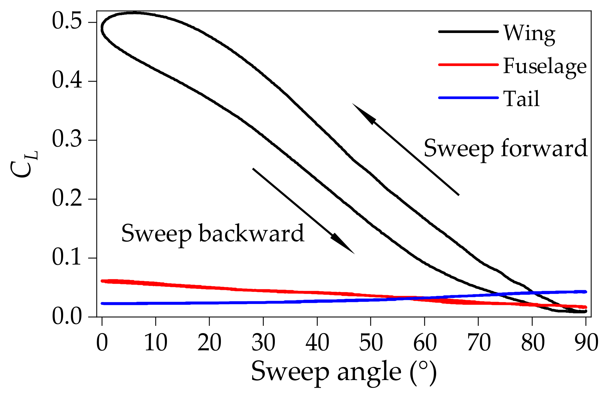
Figure 8 demonstrates that the wing exhibits a more pronounced dynamic aerodynamic behavior than the fuselage and tail. Throughout the sweep morphing, the wing undergoes the most significant change in the relative motion with the airflow, compared to the tail and fuselage. In addition, the aerodynamic interaction between the wing and the tail is reduced due to the design of the inverted V-tail configuration. As a result, the wing contributes more to the formation of the aerodynamic hysteresis loop than do the tail and fuselage, as shown in Figure 8. The subsequent investigation focuses on the flow field surrounding the wing.

4.2.1. Effect of Additional Velocity Brought by the Wing-Sweep Motion

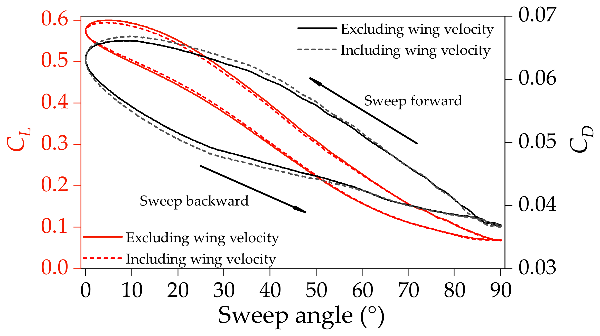
An additional relative velocity of air to the vehicle is associated with the wing-sweep motion, with the exception of the free-stream velocity. The relative motion between the wing and the free-stream changes accordingly. To obtain the effect of the additional velocity on the aerodynamic hysteresis loop, the wing velocity is included and excluded separately at the wing boundary condition in the simulations, as displayed in Figure 9. Compared to the case excluding the wing velocity, including the wing velocity results in a smaller lift hysteresis loop and a larger drag hysteresis loop. However, the variations in both hysteresis loops are small. The relative change in lift coefficient does not exceed 1.8%, and the change in the drag coefficient remains under 2.0%. Therefore, the additional velocity from the wing-sweep motion is not the major factor contributing to the formation of the aerodynamic hysteresis loop.
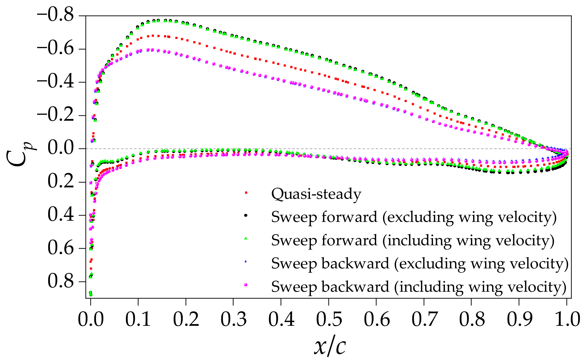
When including additional velocity from the wing-sweep motion, changes are more significant in the drag hysteresis loop than in the lift hysteresis loop, as illustrated in Figure 9. To analyze this, the pressure coefficient and shear stress on the wing surface are extracted at the cross section of y/b = 0.5, as shown in Figure 10 and Figure 11. Due to the air viscosity, the wing-sweep-forward motion slows airflow under the action of the additional velocity. This results in increased pressure coefficients on the upper wing surface, leading to a reduced lift coefficient in the case including the wing velocity, compared with the case excluding the wing velocity, as displayed in Figure 9 and Figure 10. In contrast, the wing-sweep-backward motion accelerates airflow, decreasing the pressure coefficients on the upper surface and increasing the lift coefficient in the case including the wing velocity, compared with the case excluding the wing velocity.
In addition, the additional velocity from the wing-sweep motion changes the velocity profile within the boundary layer on the wing. During the sweep-forward process, the additional velocity increases the velocity gradient within the boundary layer, which results in increased shear stress in the case including the wing velocity, compared with the case excluding the wing velocity, as shown in Figure 9 and Figure 11. In contrast, during the sweep-backward process, the additional velocity decreases the velocity gradient within the boundary layer, which results in reduced shear stress in the case including the wing velocity, compared with the case excluding the wing velocity. Compared to the pressure coefficient, the shear stress shows a greater variation. For the wing, the lift is primarily determined by the pressure distribution, while the drag is influenced by both the pressure and shear stress distributions. Therefore, the drag hysteresis loop exhibits a more significant variation.

4.2.2. Effect of Flow Structure Hysteresis

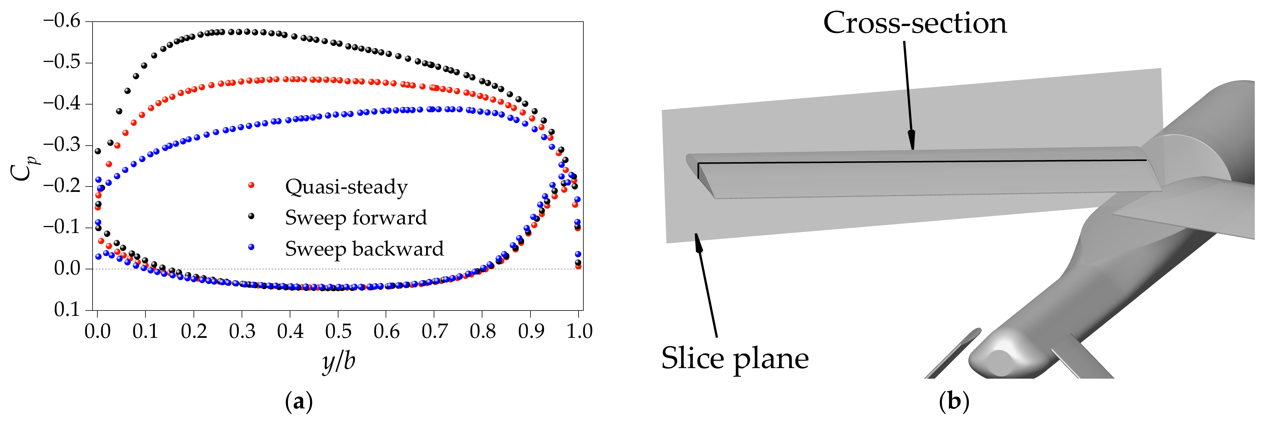
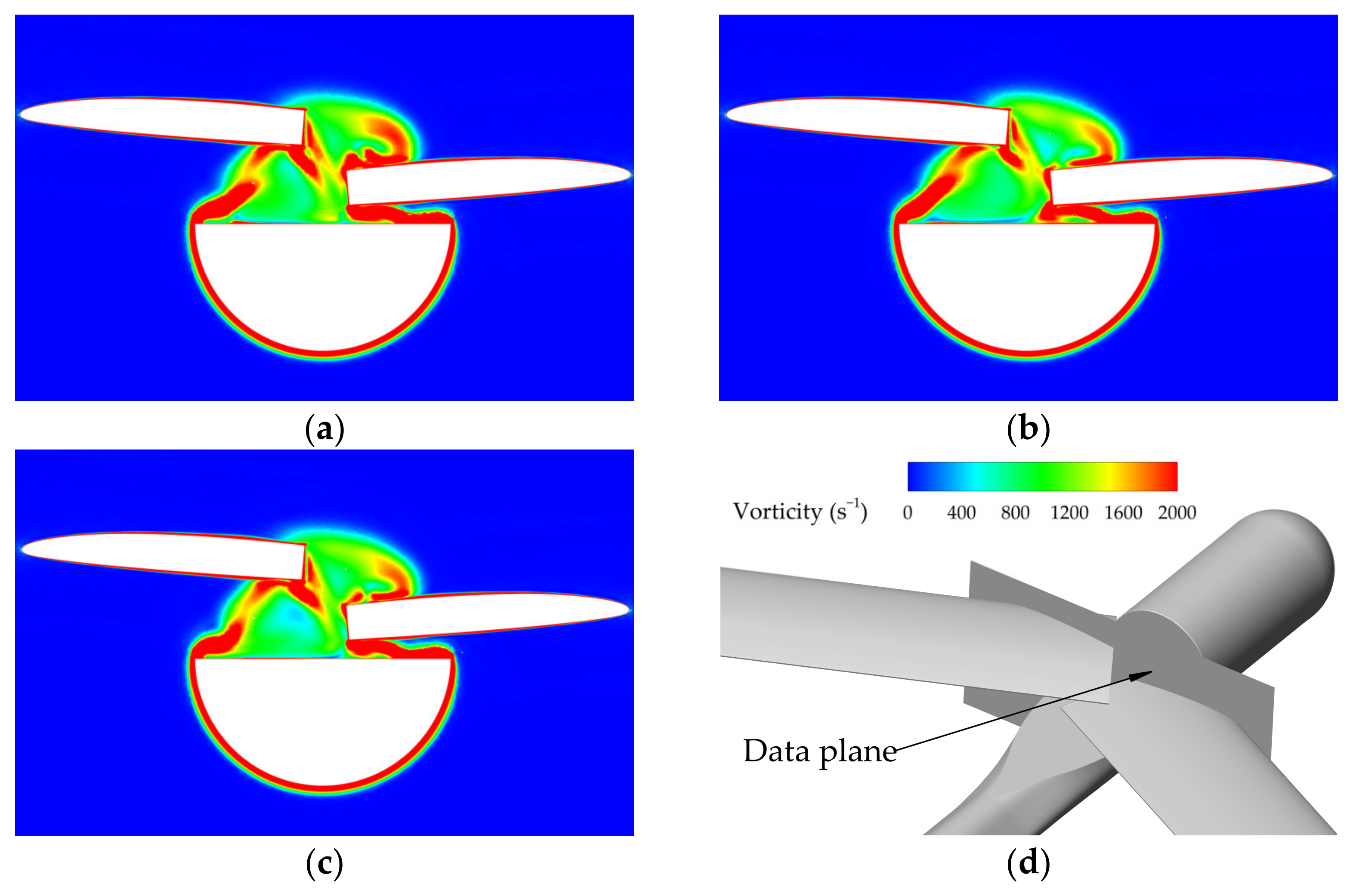
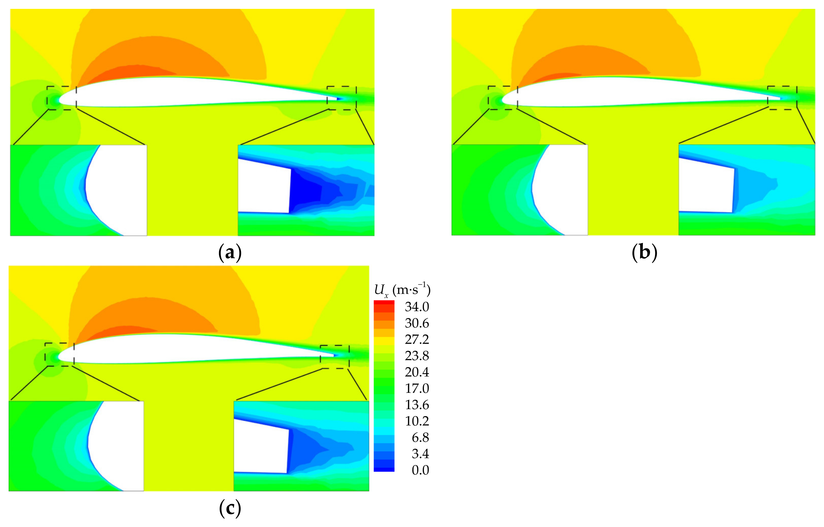
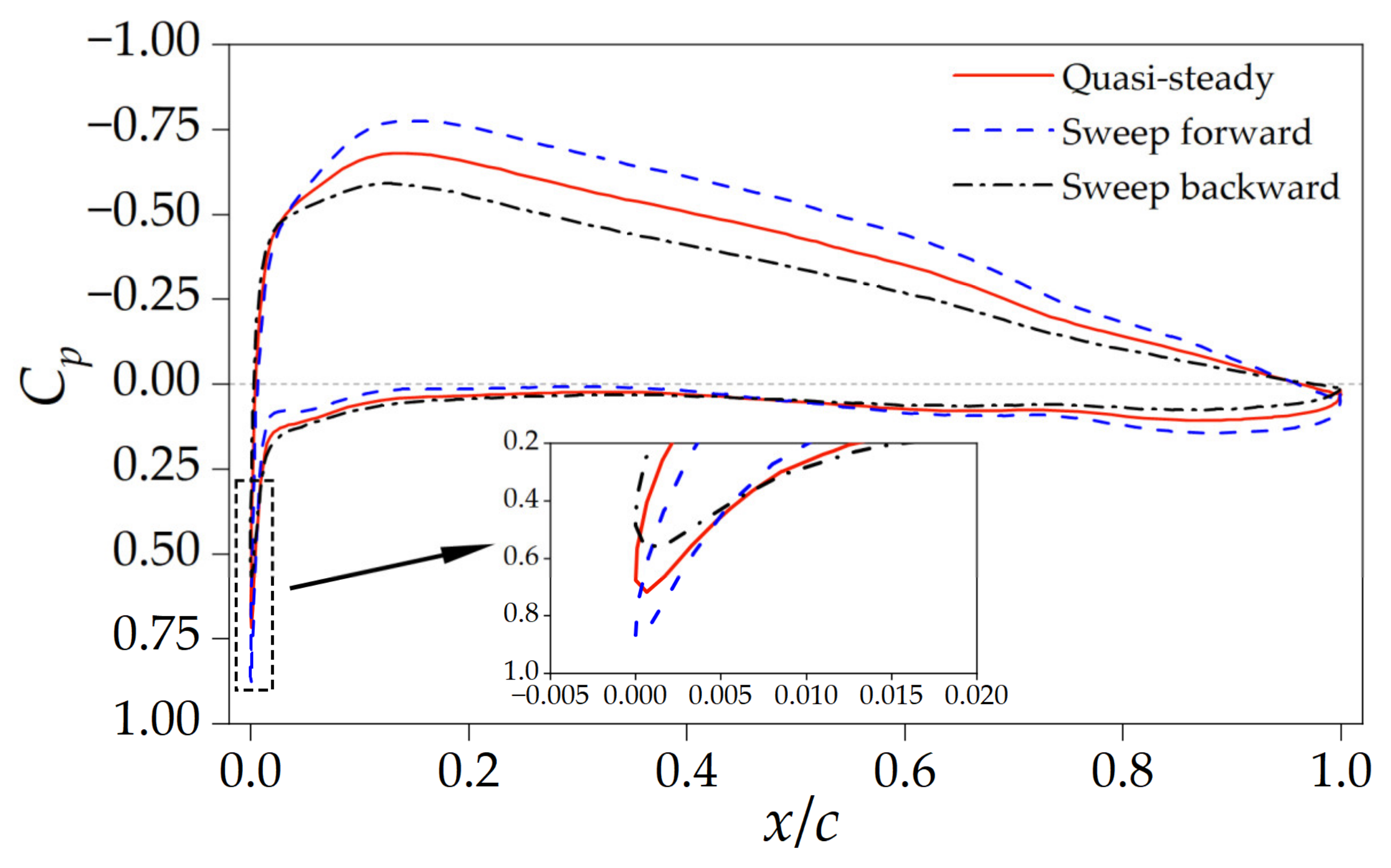
To evaluate the effect of flow field hysteresis on the aerodynamic hysteresis loop, the flow field around the tube-launched UAV with a sweep angle of 30° was analyzed. The pressure contour on the whole aircraft is shown in Figure 12. A difference can be observed between the quasi-steady and transient flow fields. Compared to the flow structure around the wing root and the tube, more significant differences in flow structure occur near the wingtip, due to the larger motion amplitude that takes place at this region during the wing-sweeping process, as shown in Figure 13 and Figure 14. To reduce the computation demands, a cross-section of y/b = 0.5 along the spanwise direction is chosen. For the states of sweeping backward, sweeping forward, and quasi-steady, the corresponding contours of velocity and pressure coefficient are shown in Figure 15 and Figure 16, respectively. The pressure coefficient distributions on the wing cross-section are shown in Figure 17. The velocity resulting from the wing-sweep morphing is excluded, and the morphing period T = 0.5 s.
Air flows from the nose to the tail of the UAV. However, during the sweeping forward process, the leading edge of the wing acts as a barrier, disrupting the smooth airflow from the nose to the tail. The surrounding flow field has not yet fully matched the geometric shape, and consequently, the velocity of the air around the leading edge is lower, as presented in Figure 15a,c. The pressure coefficient is larger than in the quasi-steady case, as shown in Figure 16a,c and Figure 17. Due to the pressure difference at the leading edge and the wing’s upper surface, the airflow above the wing demonstrates an increased velocity, as shown in Figure 15a,c, which results in a corresponding decreased pressure coefficient, as presented in Figure 17. In contrast, during the sweep-backward morphing, the airflow velocity above the wing surface is decreased, as presented in Figure 15b,c, which results in an increased pressure coefficient, as shown in Figure 17.
The UAV geometry shape changes and a corresponding wake is produced at the trailing edge during the sweep-forward process. The wake at the trailing edge from the previous moment has not fully mixed with the mainstream. The airflow velocity is lower and the pressure coefficient is higher at the trailing edge, compared to the quasi-steady case, as shown in Figure 15a,c and Figure 17. In contrast, during the sweep-backward process, the airflow speed is higher and the pressure coefficient is lower than in the quasi-steady case, as shown in Figure 15 and Figure 17.
The above analysis indicates that during the sweep-forward morphing, compared to the quasi-steady case, the pressure coefficient decreases on the upper surface and increases at the leading edge, which results in increased values for the lift coefficient and the drag coefficient. In contrast, in the sweep-backward process, compared to the quasi-steady case, the pressure coefficient increases on the upper surface and decreases at the leading edge, which leads to decreased values for the lift and drag coefficients.

4.3. Longitudinal Stability during the Sweep Morphing Process

The aerodynamic forces exhibit remarkable transient and dynamic behavior throughout the sweep morphing process, which leads to changes in the longitudinal stability of the tube-launched UAV, as presented in Figure 18. The pitching moment is defined as the moment exerted on the aircraft that causes it to rotate about its lateral axis. The reference point for both the pitching moment and the center of pressure is at the UAV nose. The positive direction of the pitching moment points to the right, while the nose-down pitching moment points to the left direction of the wing. With the sweep angle increasing, the center of pressure shifts aft and exhibits an almost linear relationship with the wing-sweep angle, as presented in Figure 18a. It can also be observed that the center of pressure shows no apparent hysteresis characteristics during the sweep morphing process.
During the sweep-backward process, when the wing-sweep angle is less than 60°, the lift coefficient exhibits an approximately linear decrease, as shown in Figure 7a, while the center of pressure shows a linear increase, as shown in Figure 18a. As a result, the nose-down pitching moment follows an approximately quadratic-curve relationship with the sweep angle, as presented in Figure 18b. The nose-down pitching moment decreases with the wing-sweep angle’s increase.
During the sweep-forward process, the nose-down pitching moment also exhibits a quadratic change, one which is similar to that observed during the sweep-backward morphing in Figure 18b. However, the nose-down pitching moment has a locally decreasing trend when the sweep angle is small. The reasons are as follows. As the wing sweeps forward to a small sweep angle, the sweep velocity of the wing gradually decreases, and the effect of the flow structure hysteresis diminishes. Consequently, the transient lift coefficients decrease progressively towards to the quasi-steady data, leading to a decrease in the rate of the lift coefficient increase and eventually resulting in negative growth. Therefore, the nose-down pitching moment increases first and then decreases during the sweep-forward process.

4.4. Flight Performance

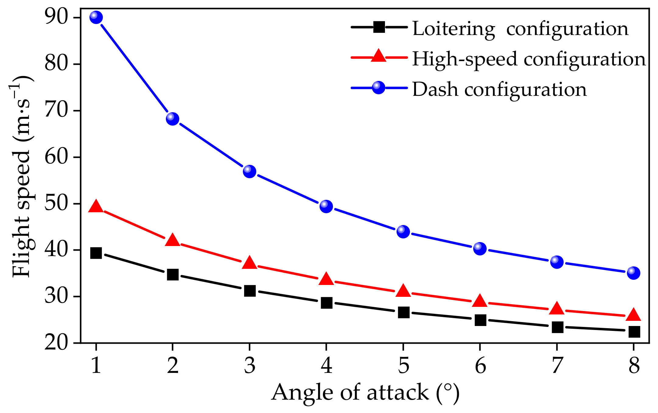
The flight speed changes with the wing-sweep angle, as shown in Figure 19. The flight speed of the loitering configuration ranges from 22.59 to 39.46 m/s by balancing drag and thrust, while that of the dash configuration ranges from 35.07 to 90.12 m/s. Thus, the tube-launched aircraft can operate across a wide speed range by adjusting the wing-sweep angle to perform multiple missions.
The flight performance of the tube-launched aircraft also changes with the wing-sweep angle, as described in Equations (2) and (3), and as shown in Figure 20. The angles of attack for the following analyses are all set to 4°. Under a configuration with a small sweep angle, the UAV exhibits a low loitering speed and power consumption. Compared to the high-speed and dash configurations, the loitering configuration shows 28.00% and 76.79% lower power consumption, respectively, and creates 38.89% and 330.81% more flight endurance. This allows for extended search times to locate targets on the ground. When tracking and capturing targets, the UAV transforms to a large sweep angle to obtain a higher flight speed. The loitering speed of the loitering configuration is 28.84 m/s. For the high-speed and dash configurations, the loitering speeds are 34.36 and 52.73 m/s, with increases of 19.14% and 82.84%, respectively. Compared to the conventional wing, the proposed variable-sweep wing offers a wider loitering speed range, from 28.84 to 52.73 m/s.
The tube-launched UAV with a variable-sweep wing can effectively match its flight speed with the moving speeds of targets by changing its configuration. This significantly reduces the response time from locating to capturing targets. Assuming a 5 km distance between the tube-launched UAV and the target, the response time for the loitering configuration is 2.89 min, while the dash configuration can respond in just 1.58 min, with a decrease of 45.33% in response time, as shown in Figure 20a.

4.5. Flight Test

To verify the effectiveness of the proposed wing-sweeping design in improving flight performance for tube-launched UAVs, a series of flight tests were conducted remotely, controlled from the ground. The CUAV X7+ Pro autopilot system mounted near the center of gravity was utilized to log flight data and manage interactions with the control surfaces and motors. This system operates with a high performance STM32H7 processor capable of running at speeds up to 480 MHz and integrates three sets of high-precision inertial measurement unit sensors: the ADIS16470, ICM42688-P, and ICM 20689. The autopilot can record various flight data, including Euler angles, three-axis acceleration, latitude, longitude, altitude, and throttle. For navigation, it employed the CUAV NEO 3 Pro GNSS module, which offers positioning accuracy up to 0.7 m. Airspeed was measured using the CUAV MS5525 airspeed sensor with Pitot tube, which can measure differential pressure from 1 to 137.9 kPa with an accuracy of 0.84 Pa. The PX4 v1.13 autopilot software was installed to control the flight operations. The PX4 software stack includes a suite of guidance, navigation, and control algorithms for autonomous UAVs. An extended Kalman filter algorithm was used to process sensor measurements and estimate the states. During the morphing process, the PX4 operated in stabilized mode, and a cascaded PID loop method was employed in the attitude controller.
Figure 21 and Figure 22 show the flight tests of the tube-launched aircraft morphing into the loiter and high-speed configurations, respectively. Table 3 shows the flight data obtained from the flight control system. The simulation data agrees well with the test data. The test results indicate that the flight speed is increased by 22.33% when the wing-sweep angle increases from 0° to 30°. It validates the finding that a wider speed range for the tube-launched aircraft can be achieved using the wing-sweeping design. The flights verify the effectiveness of the wing-sweeping design in expanding the speed range.

5. Conclusions

In this work, a tube-launched UAV with a variable-sweep wing is developed to expand the flight speed range. The transient and dynamic aerodynamic performance of the tube-launched aircraft throughout the sweep morphing process is investigated numerically. The mechanisms of the aerodynamic hysteresis loop are discussed. To verify the effectiveness of the wing-sweeping design, flight tests are performed. Based on the results, the main conclusions can be drawn as follows.
(1)
The transient lift and drag coefficients create dynamic hysteresis loops around the quasi-steady data. Compared with the quasi-steady case, the transient aerodynamic forces are smaller during the sweep-backward process, and larger during the sweep-forward process. The difference between the transient and quasi-steady aerodynamic forces increases with increases in the morphing speed.
(2)
The hysteresis effect of the flow structure, rather than the additional velocity resulting from wing-sweep morphing, is the major contributor to the aerodynamic hysteresis loop. During the wing morphing process, the flow structure takes time to match the changing geometry, resulting in a transient pressure distribution which differs from the quasi-steady distribution on the leading edge and upper wing surfaces. This discrepancy between the transient and quasi-steady cases leads to the observed differences in aerodynamic forces.
(3)
Similar to the transient aerodynamic forces, the transient pitching moment also creates a dynamic hysteresis loop around the quasi-steady data. However, the sweep morphing process does not affect the linear correlation between the center of pressure and the wing-sweep angle.
(4)
Flight testing validates the effectiveness of the proposed wing-sweeping concept for expanding the flight speed of tube-launched UAVs. The flight data obtained from flight control system agree well with the numerical data. Compared to conventional tube-launched UAVs, the tube-launched aircraft with a variable-sweep wing exhibits a wider speed range, from 22.59 to 90.12 m/s, and achieves an 82.84% increase in loitering speed.
The variable-sweep wing can be adopted to widen the speed range for tube-launched unmanned aerial vehicles. Tube-launched UAVs can carry out multiple missions on-demand when designed using the wing-sweeping method developed in this work.

Author Contributions

Writing—original draft preparation, P.S.; investigation, P.S.; conceptualization, M.W.; investigation, M.W.; methodology, M.W.; validation, Y.H.; project administration, Z.W. All authors have read and agreed to the published version of the manuscript.

Funding

This research was funded by the Fundamental Research Funds for the Central Universities, grant number 30921011201, and the National Natural Science Foundation of China, grant number 11902156.

Data Availability Statement

The data used in this analysis are not public, but available upon request.

Conflicts of Interest

Author Yongqing Huo was employed by the company Chongqing Jialing Special Equipment Co., Ltd. The remaining authors declare that the research was conducted in the absence of any commercial or financial relationships that could be construed as a potential conflict of interest.

References

  1. Zhu, Z.; Guo, H.; Ma, J. Aerodynamic layout optimization design of a barrel-launched UAV wing considering control capability of multiple control surfaces. Aerosp. Sci. Technol. 2019, 93, 105297. [Google Scholar] [CrossRef]
  2. Yang, X.; Wang, T.; Liang, J.; Yao, G.; Liu, M. Survey on the novel hybrid aquatic–aerial amphibious aircraft: Aquatic unmanned aerial vehicle (AquaUAV). Prog. Aerosp. Sci. 2015, 74, 131–151. [Google Scholar] [CrossRef]
  3. Zhang, G.Q.; Yu, S.C.M. Unsteady aerodynamics of a morphing tandem-wing unmanned aerial vehicle. J. Aircr. 2012, 49, 1315–1323. [Google Scholar] [CrossRef]
  4. Negahban, M.H.; Bashir, M.; Traisnel, V.; Botez, R.M. Seamless morphing trailing edge flaps for UAS-S45 using high-fidelity aerodynamic optimization. Chin. J. Aeronaut. 2024, 37, 12–29. [Google Scholar] [CrossRef]
  5. Papadopoulos, C.; Mitridis, D.; Yakinthos, K. Conceptual design of a novel unmanned ground effect vehicle (UGEV) and flow control integration study. Drones 2022, 6, 25. [Google Scholar] [CrossRef]
  6. Sicim Demirci, M.S.; Pecora, R.; Kaya, M.O. Design of a large-scale model for wind tunnel test of a multiadaptive flap concept. Chin. J. Aeronaut. 2024, 37, 58–80. [Google Scholar] [CrossRef]
  7. Billingsley, E.; Ghommem, M.; Vasconcellos, R.; Abdelkefi, A. Role of active morphing in the aerodynamic performance of flapping wings in formation flight. Drones 2021, 5, 90. [Google Scholar] [CrossRef]
  8. Barroso-Barderas, E.; Rodríguez-Sevillano, Á.A.; Bardera-Mora, R.; Crespo-Moreno, J.; Matías-García, J.C. Design of non-conventional flight control systems for bioinspired micro air vehicles. Drones 2022, 6, 248. [Google Scholar] [CrossRef]
  9. Dai, P.; Yan, B.; Huang, W.; Zhen, Y.; Wang, M.; Liu, S. Design and aerodynamic performance analysis of a variable-sweep-wing morphing waverider. Aerosp. Sci. Technol. 2020, 98, 105703. [Google Scholar] [CrossRef]
  10. Li, D.; Zhao, S.; Da Ronch, A.; Xiang, J.; Drofelnik, J.; Li, Y.; Zhang, L.; Wu, Y.; Kintscher, M.; Monner, H.P.; et al. A review of modelling and analysis of morphing wings. Prog. Aerosp. Sci. 2018, 100, 46–62. [Google Scholar] [CrossRef]
  11. Ozbek, E.; Ekici, S.; Karakoc, T.H. Unleashing the potential of morphing wings: A novel cost effective morphing method for UAV surfaces, rear spar articulated wing camber. Drones 2023, 7, 379. [Google Scholar] [CrossRef]
  12. Quintana, A.; Graves, G.; Hassanalian, M.; Abdelkefi, A. Aerodynamic analysis and structural integrity for optimal performance of sweeping and spanning morphing unmanned air vehicles. Aerosp. Sci. Technol. 2021, 110, 106458. [Google Scholar] [CrossRef]
  13. Wu, M.; Shi, Z.; Xiao, T.; Ang, H. Energy optimization and investigation for Z-shaped sun-tracking morphing-wing solar-powered UAV. Aerosp. Sci. Technol. 2019, 91, 1–11. [Google Scholar] [CrossRef]
  14. Ajanic, E.; Feroskhan, M.; Mintchev, S.; Noca, F.; Floreano, D. Bioinspired wing and tail morphing extends drone flight capabilities. Sci. Robot. 2020, 5, eabc2897. [Google Scholar] [CrossRef] [PubMed]
  15. Harvey, C.; Gamble, L.L.; Bolander, C.R.; Hunsaker, D.F.; Joo, J.J.; Inman, D.J. A review of avian-inspired morphing for UAV flight control. Prog. Aerosp. Sci. 2022, 132, 100825. [Google Scholar] [CrossRef]
  16. Liu, B.; Liang, H.; Han, Z.-H.; Yang, G. Surrogate-based aerodynamic shape optimization of a sliding shear variable sweep wing over a wide Mach-number range with plasma constraint relaxation. Struct. Multidiscip. Optim. 2023, 66, 43. [Google Scholar] [CrossRef]
  17. Li, H.; Chen, W.; Feng, Y.; Deng, J.; Liu, Y. Development of a novel high bandwidth piezo-hydraulic actuator for a miniature variable swept wing. Int. J. Mech. Sci. 2023, 240, 107926. [Google Scholar] [CrossRef]
  18. Chengyang, L.; Xiaotian, Z.; Ruizhi, L.; Tiandong, X. Proof-of-concept study of flexible lattice variable sweptback wing. AIAA J. 2023, 61, 1129–1141. [Google Scholar] [CrossRef]
  19. Yang, G.; Guo, H.; Xiao, H.; Liu, R.; Shi, C. Shear-driving force and critical shear angle analysis of kevlar/carbon fiber hybrid composite skins for a shear variable-sweep wing based on the classical plate theory. Appl. Compos. Mater. 2022, 29, 1871–1887. [Google Scholar] [CrossRef]
  20. Yang, G.; Guo, H.; Xiao, H.; Jiang, H.; Liu, R. Out-of-plane stiffness analysis of kevlar/carbon fiber hybrid composite skins for a shear variable-sweep wing. Appl. Compos. Mater. 2021, 28, 1653–1673. [Google Scholar] [CrossRef]
  21. Hao, F.; Tang, T.; Gao, Y.; Li, Y.; Yi, S.; Lu, J. Continuous morphing trailing-edge wing concept based on multi-stable nanomaterial. Chin. J. Aeronaut. 2021, 34, 219–231. [Google Scholar] [CrossRef]
  22. Fazelzadeh, S.A.; Rezaei, M.; Mazidi, A. Aeroelastic analysis of swept pre-twisted wings. J. Fluids Struct. 2020, 95, 103001. [Google Scholar] [CrossRef]
  23. Mir, I.; Maqsood, A.; Eisa, S.A.; Taha, H.; Akhtar, S. Optimal morphing—Augmented dynamic soaring maneuvers for unmanned air vehicle capable of span and sweep morphologies. Aerosp. Sci. Technol. 2018, 79, 17–36. [Google Scholar] [CrossRef]
  24. Chakravarthy, A.; Grant, D.T.; Lind, R. Time-varying dynamics of a micro air vehicle with variable-sweep morphing. J. Guid. Control Dyn. 2012, 35, 890–903. [Google Scholar] [CrossRef]
  25. Yan, B.; Dai, P.; Liu, R.; Xing, M.; Liu, S. Adaptive super-twisting sliding mode control of variable sweep morphing aircraft. Aerosp. Sci. Technol. 2019, 92, 198–210. [Google Scholar] [CrossRef]
  26. Greatwood, C.; Waldock, A.; Richardson, T. Perched landing manoeuvres with a variable sweep wing UAV. Aerosp. Sci. Technol. 2017, 71, 510–520. [Google Scholar] [CrossRef]
  27. Jiang, W.; Dong, C.; Wang, Q. A systematic method of smooth switching LPV controllers design for a morphing aircraft. Chin. J. Aeronaut. 2015, 28, 1640–1649. [Google Scholar] [CrossRef]
  28. Gao, L.; Zhu, Y.; Zang, X.; Zhang, J.; Chen, B.; Li, L.; Zhao, J. Dynamic analysis and experiment of multiple variable sweep wings on a tandem-wing MAV. Drones 2023, 7, 552. [Google Scholar] [CrossRef]
  29. Yan, B.; Li, Y.; Dai, P.; Liu, S. Aerodynamic analysis, dynamic modeling, and control of a morphing aircraft. J. Aerosp. Eng. 2019, 32, 04019058. [Google Scholar] [CrossRef]
  30. Bai, P.; Liu, X.; Chen, Q.; Li, F. Study on dynamic hysteresis and linear modeling of the sliding-skin variable-sweep morphing wing aerodynamics. In Proceedings of the 23rd International Congress of Theoretical and Applied Mechanics, Beijing, China, 19 August 2012. [Google Scholar]
  31. Han, H.; Hu, J.; Yu, Y. Investigation of the unsteady aerodynamic characteristics of an unmanned aerial vehicle with variable-sweep morphing. In Proceedings of the 32nd AIAA Applied Aerodynamics Conference, Atlanta, GA, USA, 16 June 2014. [Google Scholar]
  32. Zeng, L.; Liu, L.; Shao, X.; Li, J. Mechanism analysis of hysteretic aerodynamic characteristics on variable-sweep wings. Chin. J. Aeronaut. 2023, 36, 212–222. [Google Scholar] [CrossRef]
  33. Wang, Y.; He, X.; He, G.; Wang, Q.; Chen, L.; Liu, X. Aerodynamic performance of the flexibility of corrugated dragonfly wings in flapping flight. Acta Mech. Sin. 2022, 38, 322038. [Google Scholar] [CrossRef]
  34. Zhu, Z.; Song, B.; Xue, D.; Yang, W.; Lang, X.; Yang, X. Three-dimensional sweeping motion effects on hovering dragonflies. Aerosp. Sci. Technol. 2022, 127, 107701. [Google Scholar] [CrossRef]
  35. Zheng, Y.; Qu, Q.; Liu, P.; Wen, X.; Zhang, Z. Numerical analysis of the porpoising motion of a blended wing body aircraft during ditching. Aerosp. Sci. Technol. 2021, 119, 107131. [Google Scholar] [CrossRef]
  36. Kljuno, E.; Catovic, A. A generalized model for estimation of aerodynamic forces and moments for irregularly shaped bodies. Def. Technol. 2019, 15, 369–389. [Google Scholar] [CrossRef]
  37. Zhang, Z.; Li, D.; Zhou, J.; Pan, W.; Xu, Z.; Cai, J. Numerical simulation of wake vortex for the flight near the ground with different boundary conditions. Eng. Appl. Comput. Fluid Mech. 2022, 16, 484–500. [Google Scholar] [CrossRef]
  38. Wang, P.; Liu, Q.; Li, C.; Miao, W.; Yue, M.; Xu, Z. Investigation of the aerodynamic characteristics of horizontal axis wind turbine using an active flow control method via boundary layer suction. Renew. Energy 2022, 198, 1032–1048. [Google Scholar] [CrossRef]
  39. Zhang, Y.; Yan, C.; Chen, H.; Yin, Y. Study of riblet drag reduction for an infinite span wing with different sweep angles. Chin. J. Aeronaut. 2020, 33, 3125–3137. [Google Scholar] [CrossRef]
  40. Chen, F.; Yu, J.; Shen, Y.; Ma, A. Dynamic analysis of wing unfolding of tube-launched tandem-wing unmanned aerial vehicle. Acta Armamentarii 2019, 40, 89–98. [Google Scholar]
  41. Si, P.; Wu, M.; Huo, Y.; Wu, Z. Investigation on improving aerodynamics and flight performance for an unmanned aircraft with a span-extendable wing. Aerosp. Sci. Technol. 2024, 145, 108905. [Google Scholar] [CrossRef]
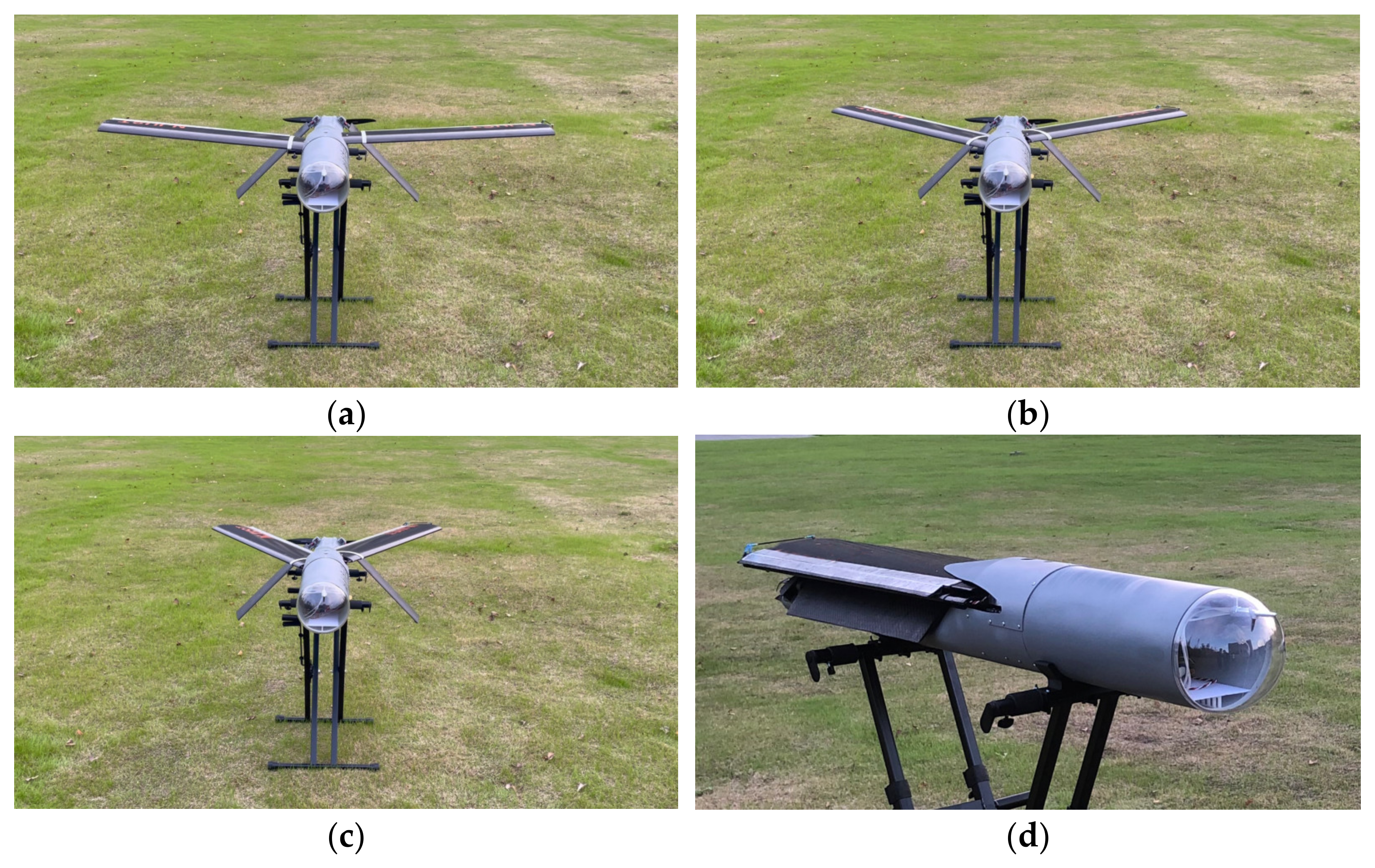
Figure 1. Prototype of the tube-launched UAV with a variable-sweep wing: (a) loitering configuration; (b) high-speed configuration; (c) dash configuration; and (d) folded configuration.
Drones 08 00474 g001
Figure 2. Mesh details of the tube-launched UAV with a variable-sweep wing: (a) assembly mesh; (b) detailed mesh near the wing root; and (c) mesh of the folded configuration.
Drones 08 00474 g002
Figure 3. Fluid domain with boundary conditions.
Drones 08 00474 g003
Figure 4. Validation of mesh size: (a) lift coefficient and (b) drag coefficient.
Drones 08 00474 g004
Figure 5. Validation of transient time step size: (a) lift coefficient and (b) drag coefficient.
Drones 08 00474 g005
Figure 6. Transient aerodynamic coefficients during the sweep morphing process under four morphing periods: (a) lift coefficient and (b) drag coefficient.
Drones 08 00474 g006
Figure 7. Relative deviations of the transient aerodynamic coefficients from the corresponding quasi-steady data throughout the sweep-backward process: (a) lift coefficient and (b) drag coefficient.
Drones 08 00474 g007
Figure 8. Aerodynamic hysteresis loops of the wing, fuselage, and tail during the sweep morphing at T = 0.5 s.
Drones 08 00474 g008
Figure 9. Aerodynamic hysteresis loops, including and excluding the wing velocity, in the numerical simulations.
Drones 08 00474 g009
Figure 10. Comparisons of pressure coefficient on wing surface excluding and including the wing velocity from the wing-sweep motion.
Drones 08 00474 g010
Figure 11. Comparisons of shear stress on the wing surface, excluding and including the wing velocity from the wing-sweep motion: (a) upper surface and (b) lower surface.
Drones 08 00474 g011
Figure 12. Pressure contour for the whole aircraft under three morphing states (T = 0.5 s, δ = 30°): (a) sweep forward; (b) sweep backward; and (c) quasi-steady.
Drones 08 00474 g012
Figure 13. Pressure coefficient distribution on the cross-section of the section plane and the left wing: (a) pressure coefficient distribution; and (b) slice plane.
Drones 08 00474 g013
Figure 14. Vorticity contour at the section plane near the combination of the wing and the tube: (a) sweep forward; (b) sweep backward; (c) quasi-steady; and (d) the slice plane.
Drones 08 00474 g014
Figure 15. Velocity contours at a spanwise section under three morphing states (T = 0.5 s, y/b = 0.5, δ = 30°): (a) sweep forward; (b) sweep backward; and (c) quasi-steady.
Drones 08 00474 g015
Figure 16. Pressure contours at a spanwise section under three morphing states (T = 0.5 s, y/b = 0.5, δ = 30°): (a) sweep forward, (b) sweep backward, and (c) quasi-steady.
Drones 08 00474 g016
Figure 17. Pressure coefficient distributions under three morphing states (T = 0.5 s, y/b = 0.5, δ = 30°).
Drones 08 00474 g017
Figure 18. Transient aerodynamic moment coefficient and location of the center of pressure versus the sweep angle during the sweep morphing process under four morphing periods: (a) location of the center of pressure and (b) nose-down pitching moment coefficient.
Drones 08 00474 g018
Figure 19. Flight speed of the tube-launched UAV versus angle of attack under three different wing-sweep angles.
Drones 08 00474 g019
Figure 20. Flight performance of the tube-launched UAV under different wing-sweep angles at an angle of attack of 4°: (a) loitering speed and response time; and (b) power consumption and flight endurance.
Drones 08 00474 g020
Figure 21. Flight testing of the tube-launched aircraft, morphing into the loiter configuration.
Drones 08 00474 g021
Figure 22. Flight testing of the tube-launched aircraft, morphing into the high-speed configuration.
Drones 08 00474 g022
Table 1. Tube-launched aircraft parameters.
ParameterSymbolValue
Mass (kg)m10
Fuselage length (m)L1.15
Battery capacity (Wh)Eb700
Table 2. Wing parameters.
ConfigurationLoiteringHigh-SpeedDash
Sweep angle (°)03060
Wingspan (m)1.41.210.7
Wing area (m2)0.280.25690.2107
Aspect ratio75.72.3
Table 3. Test results of the tube-launched aircraft at 4° angle of attack.
DataLoitering WingHigh-Speed Wing
Flight speed (m/s)29.1135.61
Power consumption (W)430605.55
Flight endurance (h)1.611.10
Error in flight speed0.93%3.51%
Error in power consumption1.27%2.63%
Error in flight endurance2.48%7.91%
Disclaimer/Publisher’s Note: The statements, opinions and data contained in all publications are solely those of the individual author(s) and contributor(s) and not of MDPI and/or the editor(s). MDPI and/or the editor(s) disclaim responsibility for any injury to people or property resulting from any ideas, methods, instructions or products referred to in the content.