Article

Fixed/Mobile Collaborative Traffic Flow Detection Study Based on Wireless Charging of UAVs

1
School of Electronic and Control Engineering, Chang’an University, Xi’an 710018, China
2
School of Energy and Electrical Engineering, Chang’an University, Xi’an 710018, China
3
College of Petroleum Engineering, Xi’an Shiyou University, Xi’an 710065, China
*
Author to whom correspondence should be addressed.
Drones 2025, 9(2), 117; https://doi.org/10.3390/drones9020117
Submission received: 20 December 2024 / Revised: 24 January 2025 / Accepted: 28 January 2025 / Published: 5 February 2025
(This article belongs to the Special Issue Urban Traffic Monitoring and Analysis Using UAVs)

Abstract

:
Accurate traffic flow detection plays a critical role in intelligent traffic control systems. However, conventional fixed video detection devices often face challenges such as occlusion and overlap in high-density traffic scenarios, which leads to distortions in vehicle detection. To address this issue, it is essential to obtain precise vehicle data as a reliable reference for managing traffic flow during peak periods. In this paper, we propose an intelligent detection scheme using an improved YOLOv8n target recognition algorithm combined with a ByteTrack multi-target tracking algorithm. A collaborative unmanned aerial vehicle (UAV) collaborative detection framework is also established, integrating UAVs and fixed detection devices to work in tandem. Such a multi-UAV collaborative data acquiring system is designed for efficient, continuous, and uninterrupted operation, employing a three-drone rotational detection strategy. UAVs offer additional flexibility and coverage in obtaining vehicle data. However, limited power could be an essential challenge to the system’s wireless physical link stability and safety. To overcome power limitations during UAV collaboration, a wireless charging (WC) system is introduced, enabling automatic constant current–constant voltage (CC-CV) switching and preventing damage from accidental data link disabling. This collaborative traffic data acquiring and transmission system ensures a stable power supply for UAVs during high-density traffic periods, supporting their reliable UAV collaborative wireless data link. Experimental results show that the collaborative detection architecture combined with wireless charging can achieve high detection accuracy, with the recognition accuracy remaining between 0.95 and 0.99.

1. Introduction

With the rapid growth in urban vehicles and the solidified saturation of road capacity, effective traffic flow guidance is an effective solution to severe congestion. Road traffic flow data collection and traffic control are critical [1,2]. At this stage, the commonly used detection methods are induction coil, ultrasonic, infrared, and video-based methods [3]. However, a common problem exists among them with the increase in traffic density, in that the detection of the accuracy seriously declines. The main reason is that the masking and overlapping generated by the increase in the density of vehicles result in fixed detection distortion. Lightweight UAVs are popular in areas such as surveillance and monitoring [4], and UAVs equipped with high-resolution cameras, sensors, and other detection devices [5] can carry out effective detection. Zhu et al. [6,7,8] used UAVs to collect road traffic data with high accuracy. Rafique et al. [9] proposed a novel vehicle detection and classification system for intelligent traffic monitoring with UAV aerial photography, which uses Kalman filtering and kernel filter-based techniques for vehicle tracking, and is effectively used for sensing road congestion, among other things. Despite the many advantages of UAVs in the field of detection, the shortcomings of their range and charging limit the inability to guarantee their continuous and long-term stable work, which affects the reliable transmission of UAV group mobile data and the stability of the link in turn [10]. In order to improve the duration of the UAV’s work, a larger capacity battery and autonomous charging base station strategy are often used. However, such methods require manual intervention, which can lead to intermittent link failure [11]. Based on this phenomenon, autonomous wireless charging design solutions have been proposed. Laser, capacitance, inductive coupling, etc., are used as common forms of charging. The laser is suitable for a long-distance range, but the cost is too high to control [12], while inductive coupling, suitable for close range, is stable and reliable. Ali Ağçal et al. [13] designed a foldable wireless charging station for drones with an efficiency of 97.66% under alignment conditions, and the wireless charging platform can be distributed on both sides of the detected roadway, solving the problems of wiring and movement limitations [14,15]. Lithium batteries are charged mainly by the S-S-S topology three-coil inductive CC-CV two-stage charging [16,17]. However, adding auxiliary coils to this system will affect the output of the secondary coil [18]. For the field of traffic flow detection, the combination of recognition and tracking architecture is mainly used for vehicle counting nowadays [19], and the commonly used recognition methods include the background subtraction and optical flow method, etc. [20]. However, this kind of method is easily affected by the adhesion of the light to the target in the area of the vehicle. Dong et al. [21] proposed an improved lightweight YOLOv5 model for vehicle recognition by merging the C3Ghost and Ghost modules in its neck structure and adding an attention mechanism to the backbone network, which improves the recognition rate while reducing the model parameters. The ByteTrack multi-target tracking algorithm can effectively recover lost objects during short-time occlusion or interaction [22], showing good robustness. Based on the above problems, to reduce the problem of vehicle occlusion in high-density hours, using mobile monitoring is a solution idea which combines vehicle recognition and tracking algorithms to obtain a high recognition accuracy. As a result, this paper proposes a fixed/mobile cooperative traffic flow monitoring framework and designs a new type of triple-coil charging device for the UAV fleet energy supply system that can actively switch between CC and CV. This device adds auxiliary clamping coils to the primary-side coils and carries out a secondary compensated S-S-SP circuit in the secondary-side coils, which can effectively protect the circuit. The vehicle identification counting module adopts the improved YOLOv8n and multi-target tracking ByteTrack algorithm combination program. According to the results of monitoring the density of traffic flow in 5 min as a cycle, switching the appropriate detection method is chosen. Based on the above design, ensuring the stable operation of the link of the UAVs can further detect road traffic flow effectively.
The layout of this paper is shown as follows: Section 1 introduces the wireless charging-based fixed/mobile collaborative traffic flow detection framework and its switching strategy. Section 2 introduces the design of a wireless charging platform for UAVs and its operation trajectory. Section 3 introduces the improved target recognition algorithm and the multi-target tracking algorithm. Section 4 presents a case study analysis. Section 5 summarizes and analyzes the whole paper.

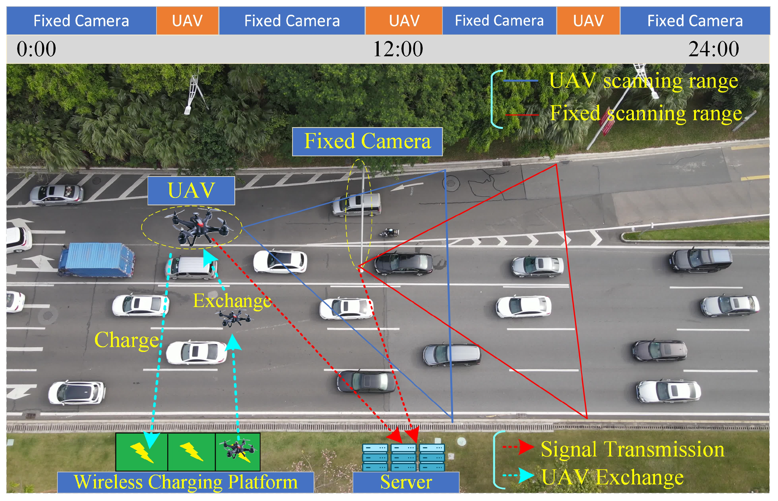
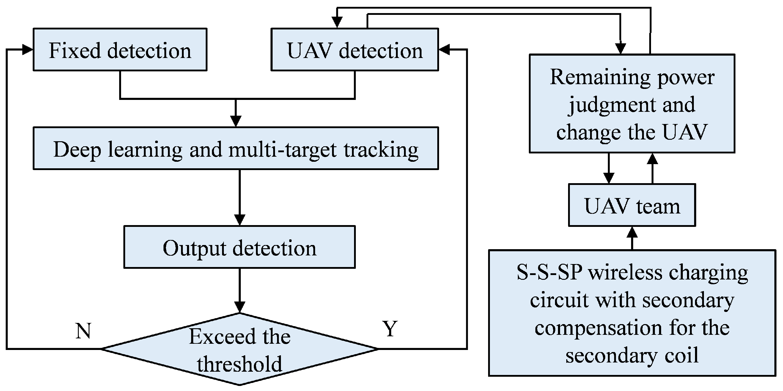
2. Fixed/Mobile Collaborative Road Traffic Detection Framework and Its Switching Strategy

In the intelligent traffic control system, traffic flow measurement is crucial. However, the commonly used fixed camera detection method will lead to the distortion of results due to overlapping and blocking in the event of significant traffic congestion or traffic accidents. Lightweight UAV equipment has outstanding performance in the traffic control system, with high flexibility and a wide field of view, etc. However, unfavorable conditions such as short endurance, inconvenient outdoor charging, etc., and the stability and continuity of the link of the UAV group during the working period cannot be guaranteed. In this paper, we propose a novel detection architecture based on the above problems, the fixed/mobile collaborative monitoring framework, as shown in Figure 1. In this architecture, the UAV adopts the three-coil wireless power supply method of constant current at constant voltage first to supplement the energy, due to the auxiliary clamping coil added to protect the battery’s durability producing mutual inductance with the primary-side coil. This mutual inductance will have a large impact on the performance of wireless charging. In order to solve the problem, a topology S-S-SP circuit is proposed, which has a secondary compensation in the secondary-side coil.
According to the set traffic thresholds and combining with target recognition and tracking algorithms, the fixed/mobile collaborative detection framework selects different detection modes. The specific detection flow is shown in Figure 2.

3. UAV Wireless Charging Design and Trajectory

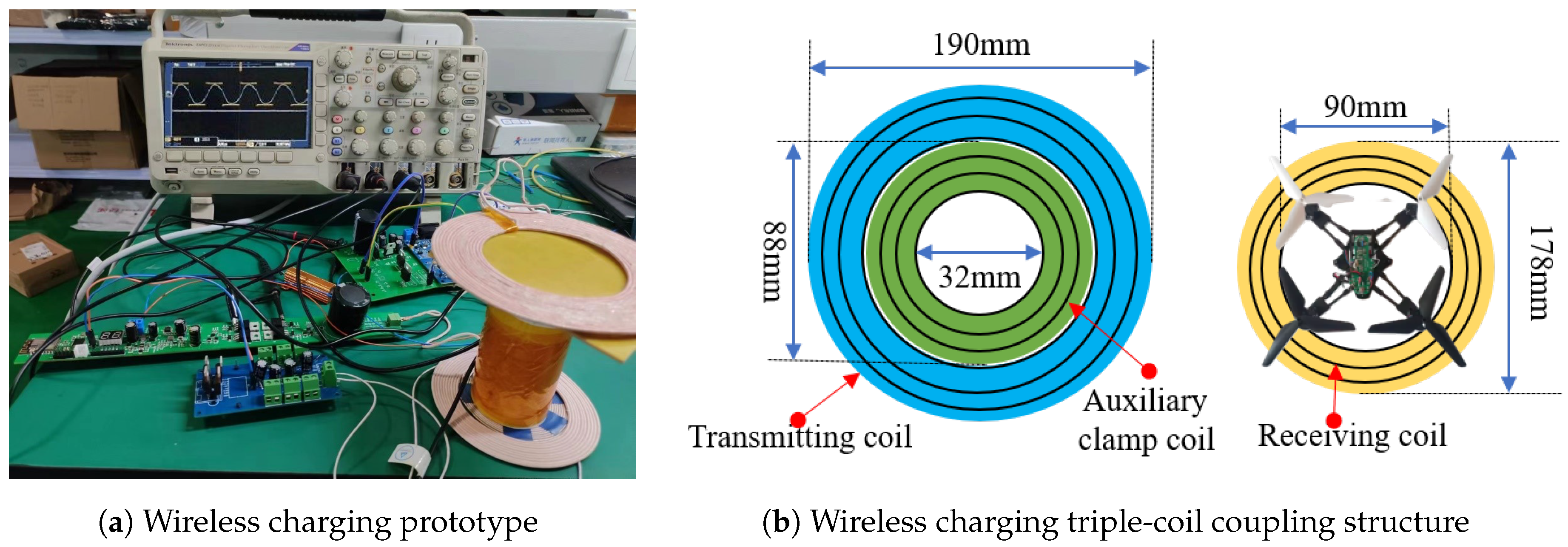
3.1. UAV Wireless Charging Platform Design

In this paper, a three-coil topology circuit with secondary compensation in the secondary coil is designed to charge the outdoor UAV equipment to guarantee the continuous operation of the UAV set.

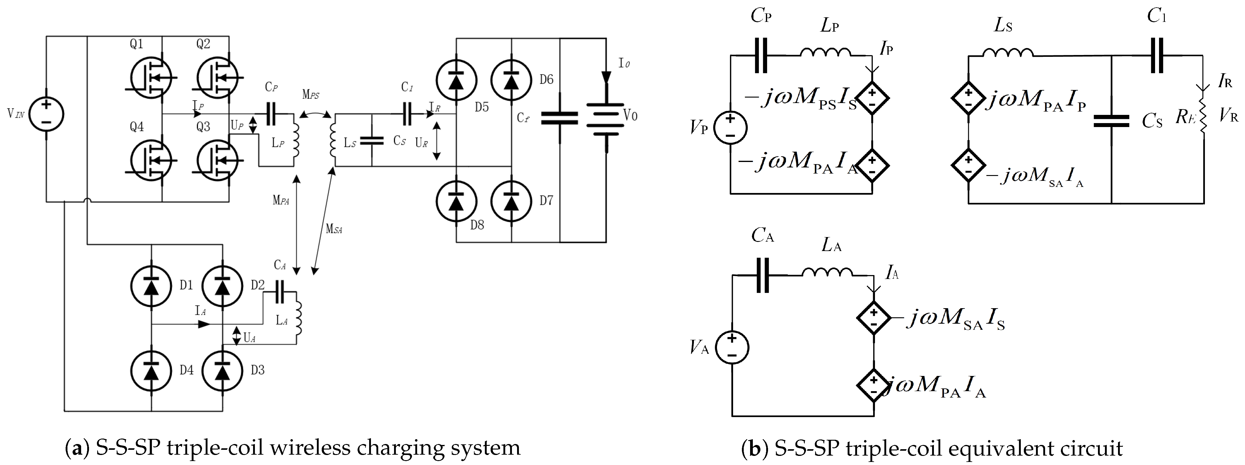
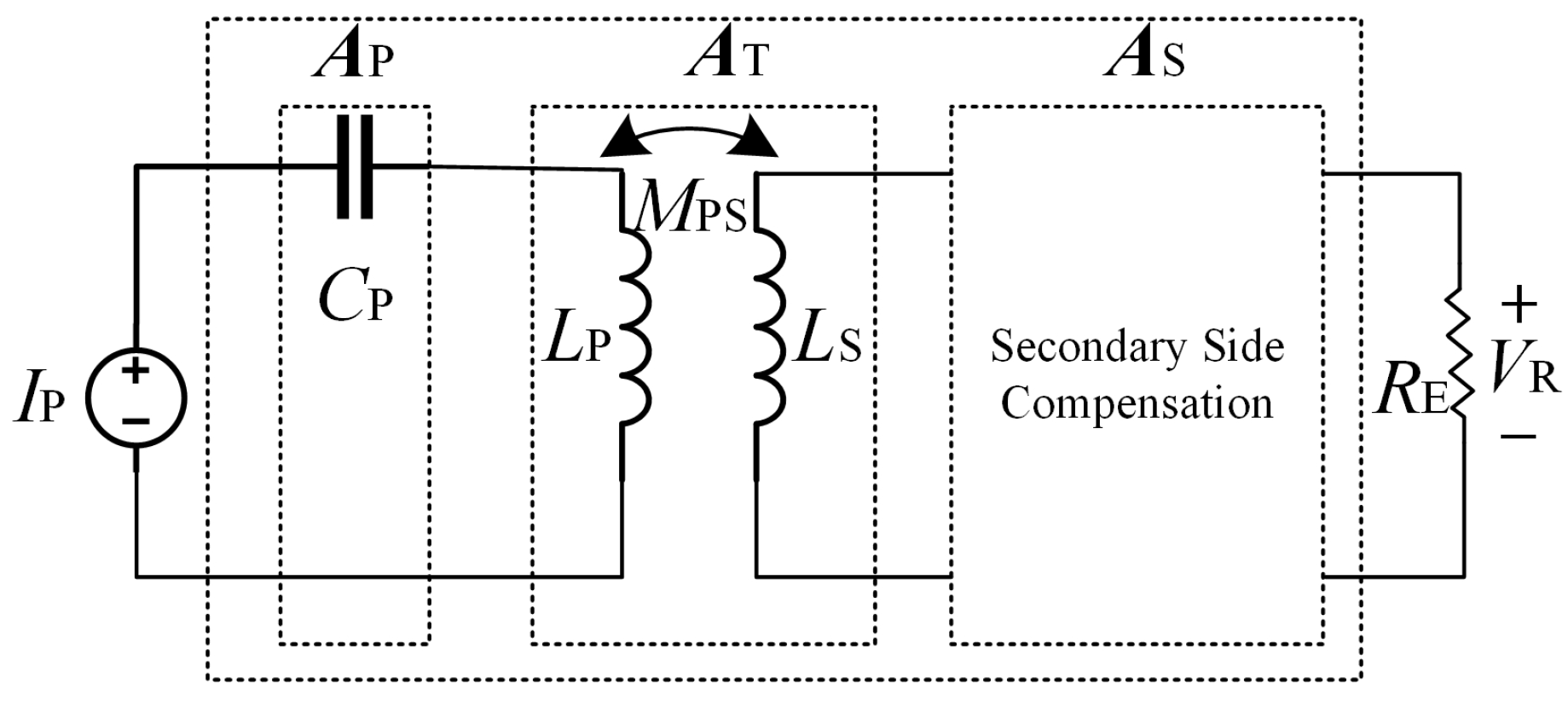
3.1.1. Derivation of the Triple-Coil S-S-SP Theory

For the S-S-S triple-coil circuit, the mutual inductance between the primary and secondary sides will be limited during the CC stage operation. The primary and secondary sides, and the primary and auxiliary sides will be jointly limited by mutual inductance during the CV stage operation. The primary and secondary edges use the S-SP compensation structure in this design. The following three states exist during the operation of this system: CC, CC-CV, and CV. The S-S-SP triple-coil wireless charging circuit structure is shown in Figure 3, where Figure 3a is the triple-coil wireless charging system, and Figure 3b is its equivalent circuit.
In the circuit of Figure 3, V P , V R , and V A denote the equivalent voltages of the circuit’s original, auxiliary, and equivalent resistors, respectively, in volts (V). L P , L A , and L S represent the resonant inductance of the primary, auxiliary, and secondary coils, respectively, in henries (H). C P , C A , and C S denote the resonant capacitance of the primary, auxiliary, and secondary coils, respectively, in farads (F). M PS , M PA , and M SA represent the magnitudes of mutual inductance between the primary and secondary, primary and auxiliary, and secondary and auxiliary coils, respectively, in henries (H). R E is the internal resistance of the battery, in ohms ( Ω ), which increases with the number of uses or the internal charge state. In this paper, the auxiliary clamp coil is designed to be small, so the value of M SA is negligible when calculating the outputs of the CV and CC stages. Although this value is weak, it can still impact the inductive power transfer (IPT) performance.
When the parameters of the triple-coil wireless charging device are determined, in the CC operating mode stage, its output current value is I R = V P j ω M PS , in amperes (A), and the output value of I R can be adjusted by changing the operating frequency or phase angle offset. In the CV operation stage, its output voltage value is V R = M PS M PA V A , which can be adjusted by changing the value of V A or by adjusting the primary–secondary compensation M PS , and the value of V R can be adjusted by changing the value of M PA .
In the CC operating mode stage, the auxiliary clamp coil is non-conducting, and the wireless charging system is equivalent to the S-S circuit structure. With the increase in electrical energy, R E also gets bigger until reaching the threshold value. At this time, the auxiliary clamp coil becomes conductive, and the operating mode is gradually transformed into the CV state. At this stage, the primary-side circuit can be regarded as a current source driving circuit in a series circuit, and then the compensation should be placed on the secondary side. A two-port network is used to analyze the triple-coil system. A, A P , A T , and A S correspond to the main circuit, primary-side circuit compensation, primary–secondary-side circuit transmission, and secondary-side compensation matrix, respectively. The relationship among the four is A = A P A T A S ; a two-port network can be represented as in Figure 4.
The values of voltage and current at the input of the two-port network are V P and I P , and the values of voltage and current at the output are V R and I R , respectively. The relationship between the ports is obtained as follows
V P I P = A V R I R .
The gain A is given by [23]:
A = 0 1 G G * 0 ,
where G = I R / V P , and G is a complex number, and G * denotes its conjugate, so Figure 4 can be expressed mathematically as follows
A = A P A T A S = 0 1 G G * 0 .
From Figure 4, A P is a single capacitor compensation, and A T is a SS topology circuit. Hence, the two-port matrix is represented as follows
A P = 1 1 j ω C P 0 1
and
A T = L P M PS j ω M P S 1 k 2 1 1 j ω M PS L S M PS ,
where k = M L P L S . Substituting (2), (4), and (5) into (3) yields
A = A S 1 1 j ω C P 0 1 L P M PS j ω M PS 1 k 2 1 1 j ω M PS L S M PS = 0 1 G G * 0 .
Equation (6) can be transformed to obtain the adjoint compensation matrix
A S = A T 1 A P 1 A = L S M PS j ω M PS j ω L P L S M PS 1 j ω M PS L P M PS 1 1 j ω C P 0 1 0 1 G G * 0 .
Equation (7) can be further simplified as follows
A S = G * L S M PS j ω C P j ω L P + G * j ω M PS L S G M PS G * ω 2 C P M PS + G * L P M PS 1 j ω M PS G .
Using the circuit principle, the compensation topology network matrix A SP in the SP compensation circuit is as follows
A SP = 1 1 j ω C 1 j ω C S C 1 + C S C 1 .
Substituting Equation (9) into (8) yields
G * L S M PS j ω C P j ω L P + G * j ω M PS = 1 L S G M PS = 1 j ω C 1 G * ω 2 C P M PS + G * L P M PS = j ω C S 1 j ω M PS G = C 1 + C S C 1 .
In the secondary side SP topology network compensation mode, the compensation capacitors C P and C S can be derived from Equation (10) as follows
C P = L S 2 C 1 ω 2 L S C 1 L P L S M PS 2 + M PS 2 C S = 1 ω 2 L S C 1 .
After determining the compensation parameters of C P and C S according to Equation (11), the value of conductance G S _ SP in the circuit is obtained by calculation as follows
G S _ SP = I R V P = j ω C 1 M PS .
When in the CC stage, the internal resistance of the battery becomes larger due to charging, which will cause the auxiliary side V A to become larger. When the value of V A exceeds the threshold value, the auxiliary side starts to conduct, and the charging state will change to CV output. Then the voltage gain can be expressed as follows
E = V R V A = V R j ω M PA I P = 1 j ω M PA G * = M PS ω 2 M PA C 1 .
Through Equations (12) and (13), it can be obtained that in the S-S-SP mode, the current value in the CC state and the voltage value in the CV state can be expressed as follows
I CC = 8 ω C 1 V IN sin π D 2 π 2 M PS V CV = M PS V IN ω 2 M PA C 1 .
When in the CC stage, according to the first term of Equation (14), the size of the output current can be adjusted by the two parameters of the operating frequency ω and voltage phase α after the parameters in the circuit system are fixed. When in the CV state, according to the second term of (14), the magnitude of the output voltage can be adjusted by changing the operating frequency ω after the parameters in the circuit system are fixed. And it can be seen that M SA does not affect the output gain of voltage and current so that it can be sized according to the demand and placed away from the area of the secondary coil. At the same time, additional compensation capacitors are added to the outside.

3.1.2. Analysis of the S-S-SP Topology Wireless Charging State

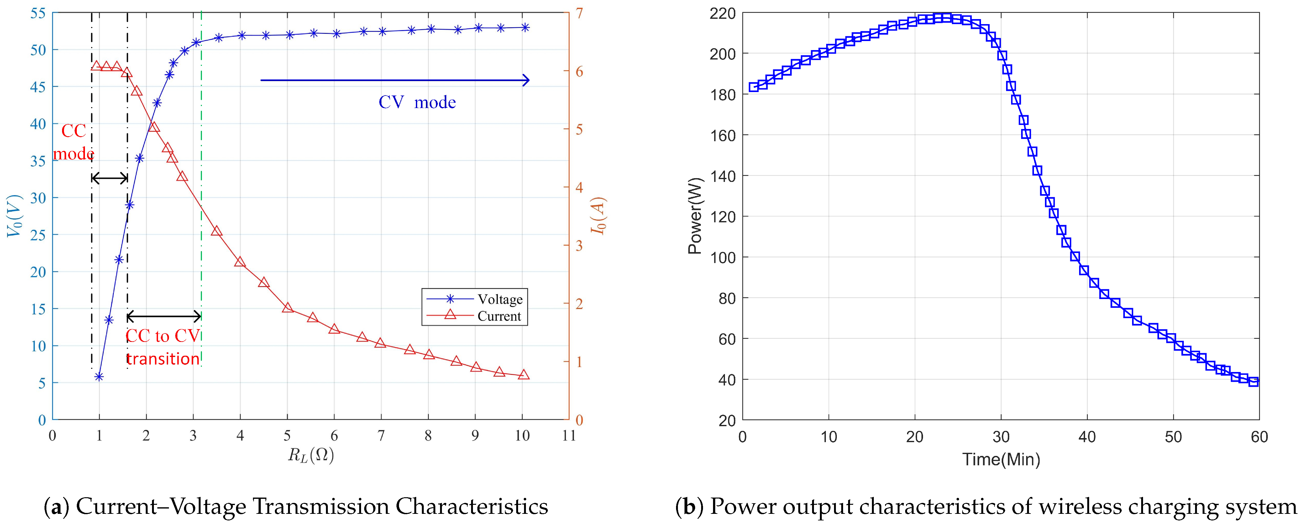
Constant Current State Analysis

From the triple-coil topology equivalent, Figure 3b, it can be seen that I P , I A , and I S are the induced currents in the triple coils, respectively, in amperes (A). V P , V A , and V S are the induced voltages of the triple coils under the action of the electromagnetic field, respectively, in volts (V). R E = 8 π 2 R L where R L denotes the vice-side equivalent loads. I R and V R denote the values of the currents and voltages inside the batteries, respectively. According to Figure 3, the principle of the circuit can be obtained as follows
V P = j ω L P j ω C P I P j ω M PS I S j ω M PA I A V A = j ω M PA I P j ω M SA I S V R = 1 ω C 1 L S j ω M PS I P j ω M SA I A = I R R E V R = I R R E V S = 1 ω C 1 L S V R = j ω M PS I P j ω M SA I A I S = j ω C s V R I R ω C 1 L S .
From Figure 3a, it can be seen that the primary-side induced voltage V P is chopped in the external DC voltage source V IN through an inverter consisting of four Metal Oxide Semiconductor Field Effect Transistors (MOSFETs). V IN is modulated through four MOSFETs, and the inverter circuit composed of four MOSFETs is a bipolar square wave, which can be obtained by unfolding its Fourier decomposition
v P ( t ) = 4 V IN π sin π D 2 sin ( ω t + θ ) ,
where the duty cycle of the induced voltage source V P is given by D.
At the initial stage, when the circuit is just turned on, the internal resistance of the battery is still minimal. According to the second term of Equation (15), the sensed voltage V A is smaller and lower than the input source voltage V IN , and the internal rectifier bridges D1, D2, D3, and D4 are not conductive, which results in the current I A on the auxiliary loop being zero all the time. Therefore, the secondary output is in the CC mode.

Constant Current to Constant Voltage Intermediate State

As the CC mode charging proceeds, the internal resistance of the battery R L is gradually increasing, and the corresponding induced voltage on the auxiliary clamp coil at this stage V A is also gradually increasing and rises to the point where it as shown in Equation (17)
V A   V IN .
Once the V A voltage meets the condition specified in Equation (17), the auxiliary clamping coil-side rectifier bridges (D1, D2, D3, D4) start to conduct, causing the I A current to gradually rise from zero. At this point, the CC output transitions to the CV output mode. From Equation (12), it is found that I R = j ω C 1 V P M PS ; substituting I R into Equation (15) gives
I P = ω 2 C 1 2 V P R E M PS 2 L S 2 M PS M SA M PA ( L S 1 ω 2 C 1 ) .
Since the system is initially in the CC mode of operation, the phase difference between the primary current I P and the secondary current I S is π 2 . Bringing I R and I P into Equation (15) and combining them with Equation (16), and taking the modulus of V A yields
V A = 4 V IN π sin π D 2 × M SA M PS 2 + ω 3 C 1 2 V P R E M PA M PS 2 L S 2 M PS M SA M PA ( L S 1 ω 2 C 1 ) 2 .
According to the condition (17) for switching the CV mode, the auxiliary clamp coil starts to conduct at this time. Bringing Equation (17) into Equation (19), the magnitude of the threshold value of the equivalent internal resistance of the battery in the circuit at the time of switching from the CC state to the CV mode can be expressed as follows
R CC = π 2 M PS 2 8 ω 3 M PA C 1 2 L S 2 M PS M SA M PA ( L S 1 ω 2 C 1 ) π 2 16 sin 2 π D 2 M SA 2 M PS 2 .
As the CV mode charging proceeds, the battery power gradually rises, and the internal resistance of the battery gradually increases and exceeds the threshold value. As charging continues, the voltage value V A in the corresponding auxiliary coil exceeds the input source voltage V IN , and the conduction angle of the rectifier bridge in the auxiliary coil gradually reaches π 2 . At this time, V A   =   4 π V dc . The rectifier bridge in the auxiliary coil is fully conducting and current begins to flow in the loop. Putting the equation V A   =   4 π V dc into Equation (19), it can be deduced that when the auxiliary clamping loop is fully conducted, the stable value of the internal resistance of the battery for the whole WC system from the intermediate transition state to the CV state is fully entered into as follows
R CV = π 2 M PS 2 8 ω 3 M PA C 1 2 L S 2 M PS M SA M PA ( L S 1 ω 2 C 1 ) 1 sin 2 π D 2 M SA 2 M PS 2 .

Constant Voltage State Analysis

When the battery CC output charging is finished, M SA starts the CV charging, which will affect the CV output. In CV mode output, there are two cases as follows:
  • At the end of the CC to CV intermediate transition state, when the equivalent resistance of the battery increases to R L R CV , the rectifier bridge in the auxiliary clamp coil reaches full conduction. The wireless charging system changes to the CV state. Due to the auxiliary clamp coil just conducting, in the auxiliary loop, current I A can be approximated as zero at this moment, and the current value of the battery I R > > I A . At this point, from bringing Equation (21) into Equation (15), it can be derived that the battery load voltage at the initial stage of CV is
    V Begin = M PS V dc ω 2 M PA C 1 L S M PS M SA M PA L S ( L S 1 ω 2 C 1 ) 1 M SA 2 M PS 2 sin 2 π D 2 .
  • After the battery charging has continued for some time, the value of I A in the auxiliary loop gradually rises, and the battery load current I R in the secondary loop gradually decreases. When the equivalent internal resistance inside the battery is much larger than R CV , I R is close to zero at this moment. In the wireless charging system, I P is in phase with V P , and I A is in phase with V A . However, there is a difference of π 2 between I P and V A , so the difference between V A and V P is π 2 . From Equation (15), by substituting the phase relationship between V P and V A , we obtain the value of its voltage at the end of the CV output as follows
    V end = M PS V dc ω 2 M PA C 1 L S 1 + M PS M SA M PA L S ( L S 1 ω 2 C 1 ) + M SA 2 M PS 2 sin 2 π D 2 2 .
According to the inference and (22) and (23), it can be seen that when the value of M SA is sufficiently small, it has less effect on the output in the CV state. Therefore, it can protect the output voltage from exceeding the threshold value of the system load battery voltage.
Analyzing Equation (15), it can be seen that when the S-S-SP triple-coil system is in regular operation, the mutual inductance value of the side between the primary and auxiliary coils M PA is larger than that between the secondary and auxiliary coils M SA . However, with the output of constant current on the secondary side, the increase in battery resistance continuously causes the decrease in the secondary loop current. In this process, the current value in the primary-side coil remains stable and almost unchanged. Meanwhile, the auxiliary loop entirely conducts as the result of the rise in the voltage in the auxiliary coil. At this time, the auxiliary loop will output voltage clamped at V end , which can protect automatically, to avoid the system being damaged when there is an open-circuit fault in the circuit.
For the above theoretical study, the wireless charging structure of a Li-ion battery is constructed as in Figure 5. In this, Figure 5a shows the constructed prototype, and the S-S-SP triple-coil coupling structure is shown in Figure 5b. The diameters of the primary, secondary, and auxiliary coils are D P = 190 mm, D S = 178 mm, and D A = 88 mm, and the corresponding inner diameters are 88 mm, 90 mm, and 32 mm, respectively.

3.2. UAV Trajectory Analysis

The battery capacity used in this UAV is 52 V/5935 mAh, and the safety range is set (0.2, 0.9) to protect the battery life. Due to the long charging time compared to the working time, three UAVs are used to realize uninterrupted continuous work.
In order to avoid the collision phenomenon during the exchange of UAVs, the trajectories of departure and return are designed as two routes. As shown in Figure 6, the starting point coordinates are (0, 0, 0.5) and the end point coordinates are (12, 8, 40.5). The trajectory models of the two routes are as follows
r 1 ( t ) = ( x 1 ( t ) , y 1 ( t ) , z 1 ( t ) ) = ( 12 · t 10 , 8 t 10 , 40 ( t 10 ) 2 )
and
r 2 ( t ) = ( x 2 ( t ) , y 2 ( t ) , z 2 ( t ) ) = ( 12 · t 10 , 8 t 10 , 40 ( t 10 ) 2 ) ,
where r 1 ( t ) denotes the going trajectory, and r 2 ( t ) denotes the returning trajectory, with all three directions in each trajectory being a function of t.

4. Analysis of Road Vehicle Recognition and Multi-Target Tracking Algorithms

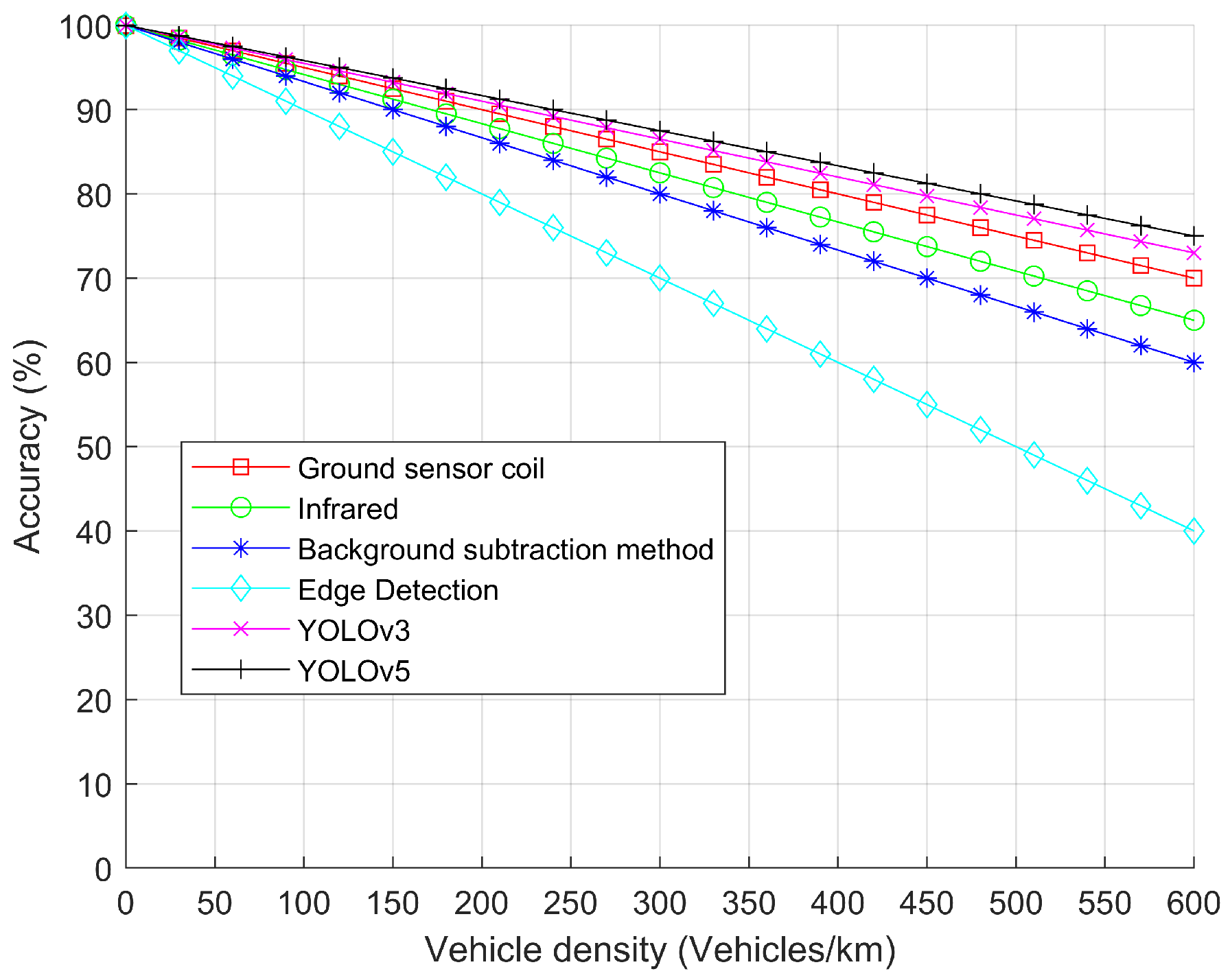
4.1. Traffic Flow Collaborative Detection Method Switching Analysis

The measurement of vehicle flow in intelligent transportation systems is crucial. Relying on a single measurement method causes certain errors. Particularly in high traffic volumes or traffic accidents, the fixed traffic flow measurements may fail. This paper proposes a collaborative fixed/mobile detection framework. The flexible WC system powers the UAV, enabling high-precision traffic flow measurement. In cases of significant traffic congestion, fixed traffic flow measurements can be distorted due to occlusion, overlapping detection frames, and other issues. Using UAVs for dynamic traffic flow measurement during high-density periods provides more accurate results. The algorithm flow is illustrated in Figure 7. According to Greenshield’s model, the relationship between traffic flow Q (vehicles/h), vehicle speed v (km/h), and vehicle density K (vehicles/km) is Q = v K . By applying Greenshield’s speed–density linear relationships in Equations (26) and (27), the traffic flow expression in Equation (28) can be derived as follows
v = v f ( 1 K K j ) ,
K = K j ( 1 v v f ) Q = v K
and
Q = v K = K j ( v v 2 v f ) ,
where K j = 1 L a v g represents the saturation value of traffic density, L a v g denotes the average vehicle occupied space, and v f refers to the free-flow speed, where the unit is (km/h).

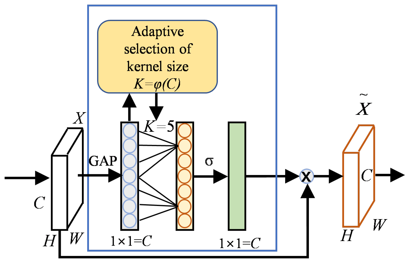
4.2. YOLOv8 Improved Algorithm with ByteTrack Tracking Algorithm

Vehicle detection tracking and traffic counting systems are important parts of the intelligent transportation system and play a vital role in transportation planning and management. For a four-lane-type urban road, K j = 600 and v f = 60 are taken. Using conventional physical methods of detection (ground sensing coil, infrared, image detection, back difference method, edge detection) and intelligent algorithm detection (YOLOv3, YOLOv5), the recognition accuracy of these six methods in different traffic densities are analyzed. The results are shown in Figure 8, from which it can be seen that each recognition method has high accuracy at times of low density. However, with the increasing density of traffic flow, recognition accuracy also decreases. In general, the accuracy of the intelligent algorithm is higher than the conventional recognition algorithm.
YOLOv8 is a significant advancement in target detection, inheriting and optimizing the architecture of YOLOv5. Several versions of the model (YOLOv8n, YOLOv8s, YOLOv8m, YOLOv8l, and YOLOv8x) were introduced to meet different computational resources and accuracy requirements. In this study, YOLOv8n is used and improved for vehicle recognition. In order to improve the target feature recognition ability in a low-light environment, the channel attention (efficient channel attention, ECA) is fused in the neck part of layers 12, 15, 16, 18, 22, 24, and 26, which is a strategy that can significantly improve the performance with only a tiny amount of parameter increase. The schematic diagram of the ECA attention mechanism is shown in Figure 9, where H, W, and C are the height, width, and number of channels of the feature map, respectively. GAP is the global average pooling, σ is the activation function, and x _ is the output feature map. The ECA mechanism first performs global average pooling for each channel of the feature map. Subsequently, it automatically determines the range of cross-channel communication by a one-dimensional convolution. The one-dimensional convolution kernel size k is in proportion to the number of channels C. The relation between the convolution kernel size k and the number of channels C is as follows
k = φ ( C ) = log 2 C γ + b γ odd ,
where γ is the scaling parameter, usually taken as 2; b is the offset, usually taken as 1; and odd denotes the nearest odd number upwards.
The ByteTrack tracking algorithm employs Kalman filtering to predict bounding boxes and then uses the Hungarian algorithm to match targets with tracks. A tracking trajectory is created for each target before starting tracking, and the next frame bounding box of each tracking trajectory is predicted by Kalman filtering. The detection frames of the targets are obtained by the detector, and the detection frames are categorized into high-scoring frames and low-scoring frames according to the confidence level:
  • For the high-scoring frame, the Intersections over Union (IoUs) of the high-scoring frame and the predicted frame are calculated, and the IoUs are matched using the Hungarian algorithm to obtain three results: the matched trajectory with the high-scoring frame, the unsuccessfully matched trajectory, and the unsuccessfully matched high-scoring frame. The boxes in the tracked trajectory are updated to high-score detection boxes after successful matching.
  • Calculating the IoUs of the low-scoring frames and the predicted frames that were not matched in the previous step is for low-scoring frames. The Hungarian algorithm is used to match the IoUs to obtain three results: matched trajectories with low-scoring frames, unsuccessfully matched trajectories, and unsuccessfully matched low-scoring frames. After successful matching, the box in the tracked trajectory is updated to the detected box.
  • The unmatched high-score detection box matches the trajectory whose status is inactive, obtaining three results: matched trajectory, unmatched detection box, and matched trajectory.
  • Update the status for the matched trajectory and mark it as deleted for the unmatched trajectory. For an unmatched detection box, the confidence is greater than the threshold +0.1 and creates a new tracking trajectory, while it is discarded if less than that.
In this paper, YOLOv8n recognition and the ByteTrack multi-target tracking algorithm are used, and a fixed/mobile cooperative detection architecture is combined for vehicle recognition counting to achieve traffic flow detection. The specific process is shown in Figure 10. Firstly, frame extraction of the captured video is carried out, and the extracted image is adjusted in resolution, normalized, and loaded. Vehicle detection is carried out, the detected results are subjected to confidence screening and non-extreme value suppression, and finally, the YOLOv8n detection results are passed to ByteTrack for tracking and counting.

5. Simulation Design and Results Analysis

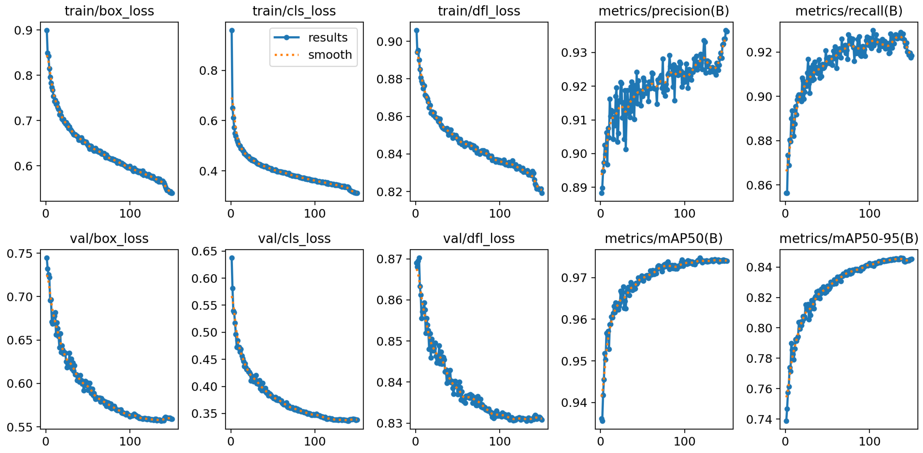
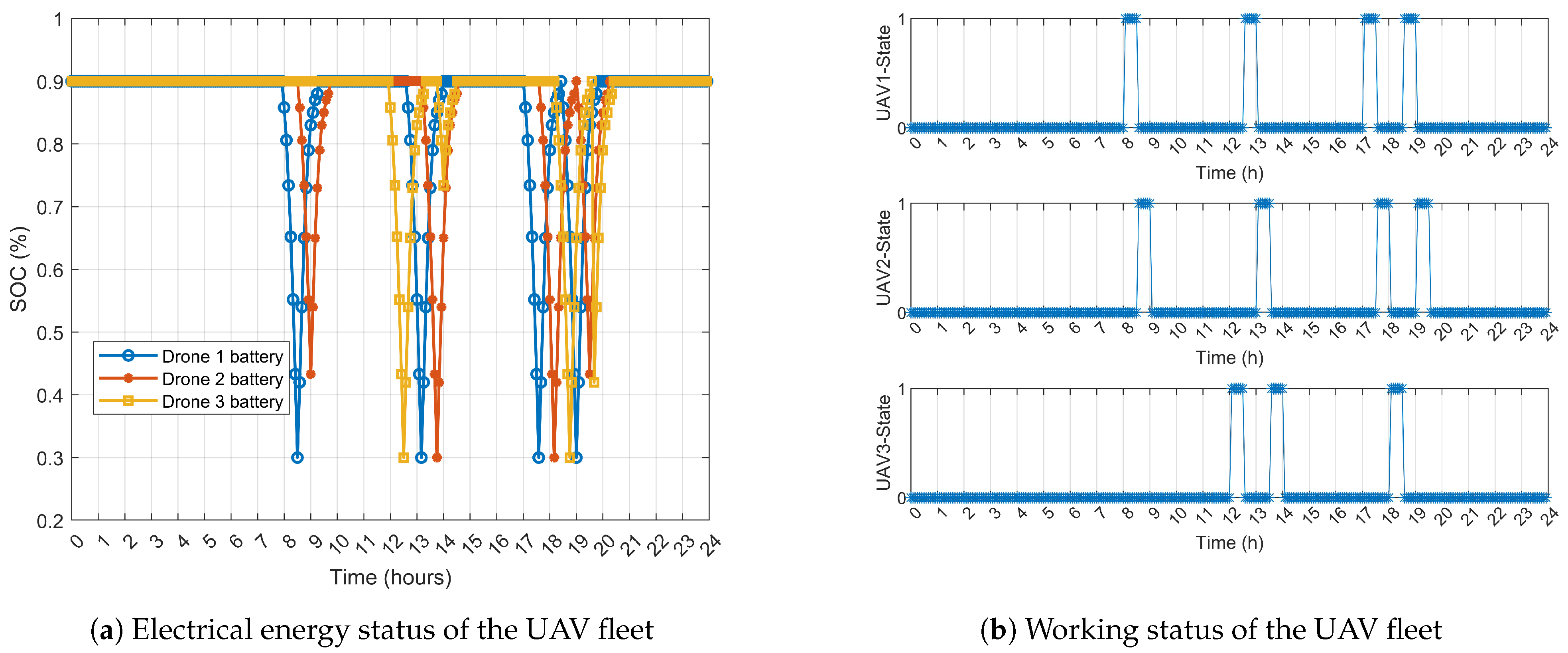
5.1. Parameter Settings

The three coils adopt a coaxial coupling structure in this wireless charging design. D P , D S , D A are the outer diameters of the three coils on the primary, secondary, and auxiliary sides, respectively. N P , N S , N A correspond to the number of turns of the three coils. C P , C S , C A , C 1 are the compensation parameters in the system. There exists a certain air gap between the primary and secondary coils, the size of which is 45 mm. In this design, the secondary side is compensated using the SP topology, and when the values of the three parameters L P , L S , L A are determined, the output of the system in CV mode can be changed by varying the values of C A and C 1 for regulation. The MOSFET half-cycle on/off ratio is 0.95, and the application of DSPIC30F4013 to control the internal duty cycle of the converter is 0.95, as well as the system operating frequency being 100 kHz. The specific parameter values are shown in Table 1.
The dataset is derived from 8 h of video footage captured by a Canon EOS 550 and a DJI Mavic 3 at 12 different locations in Xi’an, China, focusing on monitoring and UAV applications. OpenCV was used to extract video frames as images. A total of 9860 images were utilized, which includes 7888 for training and 1972 for validation, following an 8:2 ratio. The weather conditions in the dataset are categorized into sunny, cloudy, night, snowy, and rainy days. The dataset incorporates multiple scenario features, as shown in Figure 11, which helps to demonstrate the generalization capability of the model better.
The experimental environment uses a Windows 11 64-bit operating system, with an Intel(R) Core (TM) i7-14700K central processing unit and an NVIDIA GeForce RTX 4060 graphics processing unit. The compilation environment is PyCharm 2022.3, with Python 3.9 as the interpreter. The following libraries are imported: Numpy 1.26.1, torch 1.9.0, matplotlib 3.8.0, ultralytics 8.0.199, and PyQt5 5.15.2, among others.
The input image is set to a resolution of 640 × 640 pixels, with the Epoch set to 150, batch size to 16, and learning rate to 0.01. The training process primarily involves three types of loss functions: positioning loss, classification loss, and dynamic feature loss. Some evaluation metrics are shown in Figure 12. The PR curve is used to illustrate the relationship between precision and recall, and the PR curve for this training is shown in Figure 13. It can be observed that the average mAP@0.5 for target detection is 0.974, which meets the performance requirements.

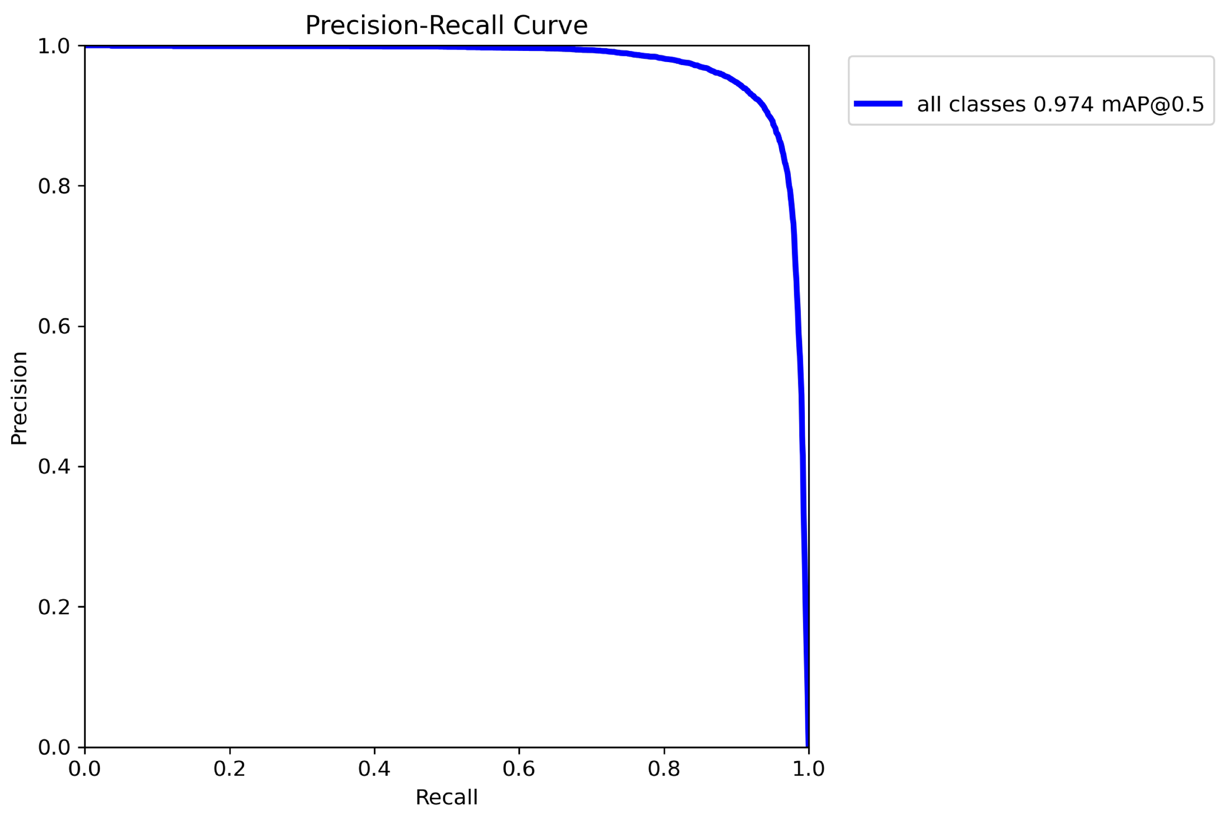
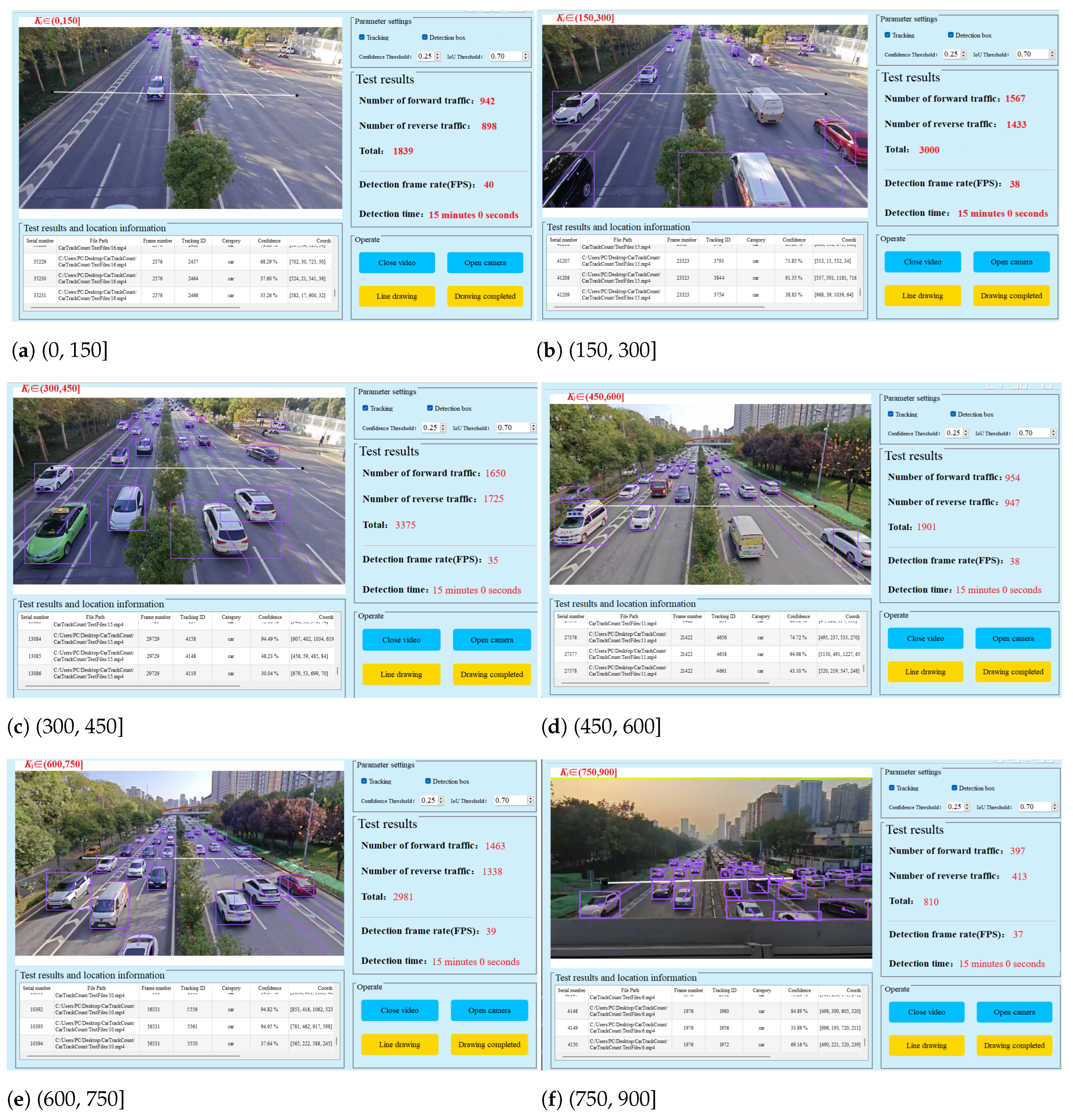
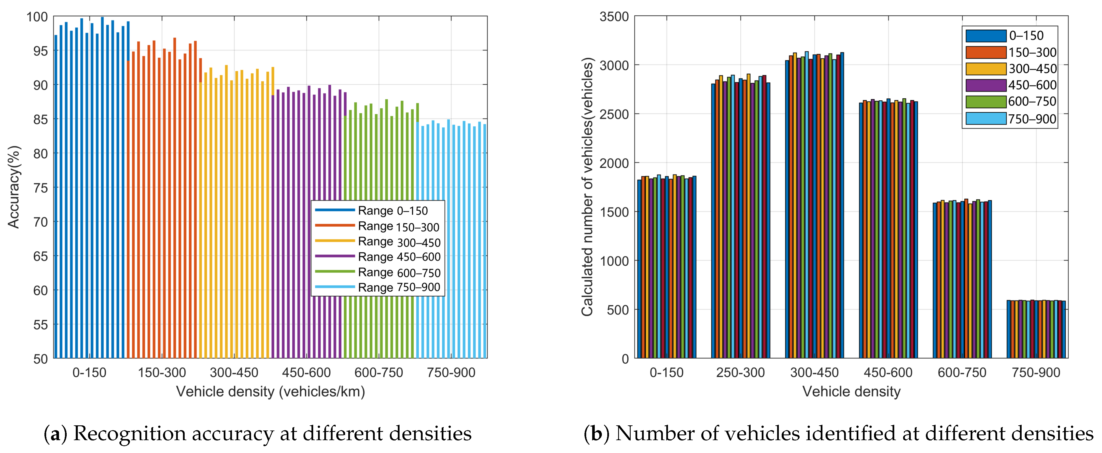
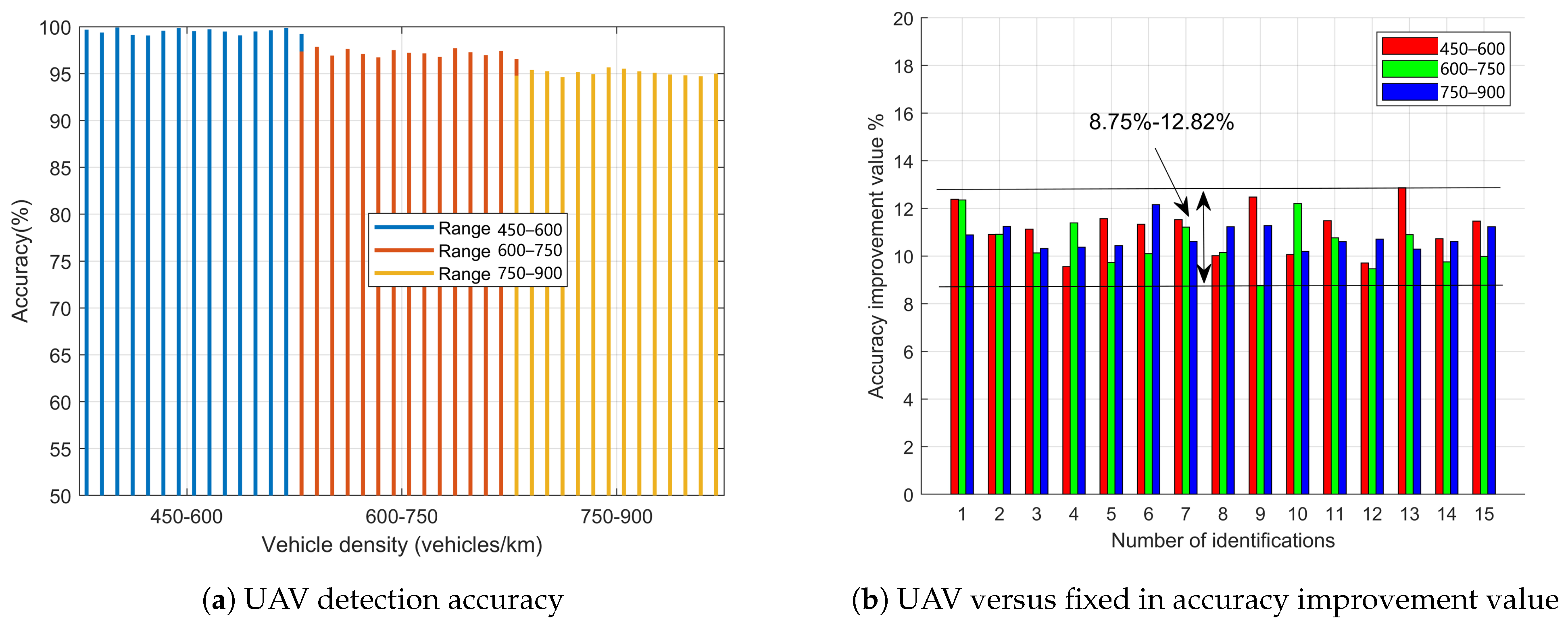
5.2. Validation Analysis

A 52V/5935 mAh lithium battery is selected as the UAV power supply for charging. The current on both sides of the load battery in the receiving circuit of the UAV is 6A when fully charged. It takes 80 min to charge from 0% to 100%, and 60 min to charge within the battery’s safety range S O C ( 0.2 , 0.9 ) . The total weight of the UAV and the load is 1.6 kg, with a working time of 35 min in the load state, and the parameters are shown in Table 2. The transmission characteristics of the S-S-SP triple-coil charging system are obtained through experimental analysis, as shown in Figure 14. Figure 14a shows the actual measurement curve of real-time changes in the secondary output voltage, output current, and equivalent resistance of the charging battery during IPT system charging. Figure 14b presents the measured output power curve. As the resistance increases, the power drops sharply in the CV state, while the earlier stages maintain a high power output.
Using a two-way 6-lane road, K j = 900 and v f = 60 . Firstly, a fixed camera is used to detect different traffic densities based on the YOLOv8n and ByteTrack tracking algorithms, with a confidence threshold of 0.25 and a cross-ratio threshold of 0.7. Multiple verifications of 15 min each are performed using six different traffic densities, and the recognition process is shown in Figure 15.
According to the identified data analysis, when the traffic density is low, the recognition accuracy remains high and above 0.93 typically. However, as the traffic density increases, the recognition accuracy decreases. The recognition results are shown in Figure 16, with 15 repetitions for each vehicle density. Figure 16a illustrates the recognition accuracy under varying traffic densities, while Figure 16b shows the total number of vehicles identified within 15 min for each traffic density. It can be observed that although the traffic density increases, the total traffic volume does not correspondingly increase.
This paper proposes a vehicle recognition framework based on the collaboration between fixed cameras and wireless charging UAVs. From the results presented in Figure 16, it is evident that when traffic density reaches K > 450 , the detection accuracy drops below 0.9. As traffic density increases, occlusion, overlap, and variations in target scale make it challenging for ByteTrack to distinguish and track individual vehicles under high-density conditions accurately. Therefore, wireless charging UAVs are employed for detection when traffic density ranges from 450 to 900. These UAVs, equipped with trained YOLOv8n and ByteTrack models, perform identification and tracking. The UAV perspective effectively mitigates occlusion and overlap issues. Traffic density analysis reveals that high-density periods are mainly concentrated between 8:00 and 9:00, 12:00 and 14:00, and 17:00 and 19:30. To ensure continuous operation, three UAVs are deployed sequentially, operating within the designated battery safety limits. Each UAV has a maximum operational time of 35 min under load. After 30 min of operation, the second UAV will take off alternately, allowing the previous UAV to return to the wireless charging device for recharging. This process continues in sequence.
The results of the UAVs’ detection in high-density hours are shown in Figure 17. From Figure 17a, it can be seen that even if the density of the road section is close to saturation, the accuracy of the UAVs can still be kept above 0.95. Figure 17b shows the difference between the accuracy of the UAVs and that of the fixed detection in the high-density hours, from which it can be seen that the UAVs can improve the accuracy by 8.75–12.82%.
In the monitoring process, uninterrupted judgment of the traffic density is needed and different monitoring modes are switched. The judgment period is set, and the drones are used to detect during the time period when the traffic density is high. The states of the three groups of drones are shown in Figure 18. Figure 18a shows the battery power state of the three groups of UAVs during operation. Figure 18b shows the working state of drones, in which one means working, and zero means charging or waiting.

6. Conclusions

Urban road traffic flow detection is becoming increasingly important in the development of intelligent transport, and accurate traffic flow information can effectively support road traffic regulation, ease traffic congestion, and reduce traffic accidents. In this paper, to ensure that the UAV link continues to work safely and improve the accuracy of road vehicle recognition, we propose a fixed and mobile cooperative detection architecture and switch the detection device according to the traffic density in time. The improved YOLOv8n target recognition and ByteTrack multi-target pursuit algorithms are used to recognize and count road vehicles. In order to facilitate UAV charging and guarantee the continuous and stable operation of the serial UAV link, an S-S-SP triple-coil compensation network wireless charging platform possessing secondary compensation in the secondary coil is designed, which is capable of actively and smoothly switching the triple-coil WC system with constant current–constant voltage charging mode conversion. This platform can effectively avoid the accidental opening of the circuit that causes the UAVs’ working link to fail, which guarantees the working safety of the system. At the same time, under the action of the auxiliary coil, the system’s voltage output gain is not interfered with by the internal parameters of the system. It can actively adjust the battery charging according to the load changes, which significantly improves the flexibility and safety of the system design. The experimental verification of the proposed hybrid cooperative detection structure can effectively improve the accuracy of road vehicle recognition, and the accuracy can be maintained at more than 0.95 at times of high density, which can provide adequate data support for traffic flow regulation and reduce traffic accidents.

Author Contributions

Conceptualization, H.W. and M.N.; methodology, K.Y.; software, B.W.; validation, Y.L. and H.P.; formal analysis, H.W. and M.N.; investigation, M.N.; resources, K.Y.; data curation, H.W.; writing—original draft preparation, H.W.; writing—review and editing, M.N.; visualization, B.W.; supervision, M.N., K.Y. and B.W.; project administration, B.W. and Y.L.; funding acquisition, B.W. and M.N. All authors have read and agreed to the published version of the manuscript.

Funding

This research was supported, in part, by the National Key R&D Program of China (Grant No. 2021YFB1600205), an Innovation Creative Centre project of Shaanxi Province (Grant No. S2022-ZC-GXYZ-0015), the Fundamental Research Funds for the Central Universities, CHD, China (Grant No. 300102384901), and a Provincial High Level Thousand-Talent Project, Shaanxi, China (Grant No. 300201000156).

Data Availability Statement

Data are unavailable due to privacy.

Conflicts of Interest

The authors declare no conflicts of interest.

References

  1. Huang, H.; Li, W.l.; Niu, M.; Miah, M.S.; Gao, T.; Wang, H.f. A Long-term Vehicle Tracking Algorithm of Correlation Filter Optimized by Swarm Intelligence Tracking Framework. IEEE Trans. Geosci. Remote. Sens. 2024, 62, 1002216. [Google Scholar] [CrossRef]
  2. Huang, H.; Wen, X.; Niu, M.; Miah, M.S.; Gao, T.; Wang, H. Multi-UAVs assisted path planning method for terrain-oriented air-ground collaborative vehicular network architecture. IEEE Trans. Intell. Veh. 2024; early access. [Google Scholar]
  3. Yong, H.; Pei, G.; Qinhua, W.; Wenhui, W. Research on image processing and pattern recognition method of rolling bearing cage defects. Acta Instrumenta Sin. 2019, 40, 162–169. [Google Scholar]
  4. Sujit, P.; Ghose, D. Search using multiple UAVs with flight time constraints. IEEE Trans. Aerosp. Electron. Syst. 2004, 40, 491–509. [Google Scholar] [CrossRef]
  5. Sarunic, P.; Evans, R. Hierarchical model predictive control of UAVs performing multitarget-multisensor tracking. IEEE Trans. Aerosp. Electron. Syst. 2014, 50, 2253–2268. [Google Scholar] [CrossRef]
  6. Zhu, J.; Sun, K.; Jia, S.; Li, Q.; Hou, X.; Lin, W.; Liu, B.; Qiu, G. Urban traffic density estimation based on ultrahigh-resolution UAV video and deep neural network. IEEE J. Sel. Top. Appl. Earth Obs. Remote Sens. 2018, 11, 4968–4981. [Google Scholar] [CrossRef]
  7. Brkić, I.; Miler, M.; Ševrović, M.; Medak, D. An analytical framework for accurate traffic flow parameter calculation from UAV aerial videos. Remote Sens. 2020, 12, 3844. [Google Scholar] [CrossRef]
  8. Song, H.; Liang, H.; Li, H.; Dai, Z.; Yun, X. Vision-based vehicle detection and counting system using deep learning in highway scenes. Eur. Transp. Res. Rev. 2019, 11, 51. [Google Scholar] [CrossRef]
  9. Rafique, A.A.; Al-Rasheed, A.; Ksibi, A.; Ayadi, M.; Jalal, A.; Alnowaiser, K.; Meshref, H.; Shorfuzzaman, M.; Gochoo, M.; Park, J. Smart traffic monitoring through pyramid pooling vehicle detection and filter-based tracking on aerial images. IEEE Access 2023, 11, 2993–3007. [Google Scholar] [CrossRef]
  10. Lee, B.; Kwon, S.; Park, P.; Kim, K. Active power management system for an unmanned aerial vehicle powered by solar cells, a fuel cell, and batteries. IEEE Trans. Aerosp. Electron. Syst. 2014, 50, 3167–3177. [Google Scholar] [CrossRef]
  11. Ahmadian, N.; Lim, G.J.; Torabbeigi, M.; Kim, S.J. Smart border patrol using drones and wireless charging system under budget limitation. Comput. Ind. Eng. 2022, 164, 107891. [Google Scholar] [CrossRef]
  12. Bin Junaid, A.; Konoiko, A.; Zweiri, Y.; Sahinkaya, M.N.; Seneviratne, L. Autonomous wireless self-charging for multi-rotor unmanned aerial vehicles. Energies 2017, 10, 803. [Google Scholar] [CrossRef]
  13. Ağçal, A.; Doğan, T.H. A Novel Folding Wireless Charging Station Design for Drones. Drones 2024, 8, 289. [Google Scholar] [CrossRef]
  14. Wang, H.; Chau, K.; Lee, C.H.; Cao, L.; Lam, W.H. Design, analysis, and implementation of wireless shaded-pole induction motors. IEEE Trans. Ind. Electron. 2020, 68, 6493–6503. [Google Scholar] [CrossRef]
  15. Xue, Z.; Niu, S.; Li, X. A Simplified Multivector-Based Model Predictive Current Control for PMSM With Enhanced Performance. IEEE Trans. Transp. Electrif. 2023, 9, 4032–4044. [Google Scholar] [CrossRef]
  16. Mahesh, A.; Chokkalingam, B.; Mihet-Popa, L. Inductive wireless power transfer charging for electric vehicles–a review. IEEE Access 2021, 9, 137667–137713. [Google Scholar] [CrossRef]
  17. Huang, Z.; Lam, C.S.; Mak, P.I.; da Silva Martins, R.P.; Wong, S.C.; Chi, K.T. A single-stage inductive-power-transfer converter for constant-power and maximum-efficiency battery charging. IEEE Trans. Power Electron. 2020, 35, 8973–8984. [Google Scholar] [CrossRef]
  18. Huang, Z.; Wang, G.; Yu, J.; Qu, X. A novel clamp coil assisted IPT battery charger with inherent CC-to-CV transition capability. IEEE Trans. Power Electron. 2021, 36, 8607–8611. [Google Scholar] [CrossRef]
  19. Zhendong, H.; Yaonan, W.; Jie, L.; Feng, Y. High speed rail surface defect image segmentation based on background difference. Acta Instrumenta Sin. 2016, 37, 640–649. [Google Scholar]
  20. Tian, Y.; Liu, S.; Tan, Q. Application of Detecting Part’s Size Online Based on Machine Vision. Energy Procedia 2012, 16, 1948–1956. [Google Scholar]
  21. Dong, X.; Yan, S.; Duan, C. A lightweight vehicles detection network model based on YOLOv5. Eng. Appl. Artif. Intell. 2022, 113, 104914. [Google Scholar] [CrossRef]
  22. Li, X.; Yin, P.; Qu, Y.; Duan, C. Research on Multi-Object Tracking Algorithm for Thyroid Nodules Based on ByteTrack. In Proceedings of the 2024 IEEE 3rd International Conference on Electrical Engineering, Big Data and Algorithms (EEBDA), Changchun, China, 27–29 February 2024; pp. 1589–1592. [Google Scholar]
  23. Zhang, Y.; Shen, Z.; Pan, W.; Wang, H.; Wu, Y.; Mao, X. Constant current and constant voltage charging of wireless power transfer system based on three-coil structure. IEEE Trans. Ind. Electron. 2022, 70, 1066–1070. [Google Scholar] [CrossRef]
Figure 1. Fixed/mobile collaborative traffic detection framework.
Drones 09 00117 g001
Figure 2. Fixed/mobile collaborative detection selection process.
Drones 09 00117 g002
Figure 3. Triple-coil wireless charging design.
Drones 09 00117 g003
Figure 4. Two-port equivalent circuit of the secondary compensation network.
Drones 09 00117 g004
Figure 5. Wireless charging device structure.
Drones 09 00117 g005
Figure 6. Schematic of UAV flight trajectory.
Drones 09 00117 g006
Figure 7. Schematic diagram for switching between collaborative detection methods.
Drones 09 00117 g007
Figure 8. Accuracy of each algorithm under different vehicle densities.
Drones 09 00117 g008
Figure 9. Principles of the ECA attention mechanism.
Drones 09 00117 g009
Figure 10. Identifying the detection counting process.
Drones 09 00117 g010
Figure 11. Traffic dataset example.
Drones 09 00117 g011
Figure 12. Model evaluation indicators.
Drones 09 00117 g012
Figure 13. PR curve.
Drones 09 00117 g013
Figure 14. S-S-SP triple-coil wireless charging system transmission characteristics.
Drones 09 00117 g014
Figure 15. Identification process of different traffic densities.
Drones 09 00117 g015
Figure 16. Analysis of fixed detection under different traffic densities.
Drones 09 00117 g016
Figure 17. UAVs’ detection during periods of high traffic density.
Drones 09 00117 g017
Figure 18. The state of the UAV fleet at different moments.
Drones 09 00117 g018
Table 1. Wireless charging device parameter settings.
D P = 190 mm L P = 85.22 μH
D S = 178 mm L A = 70.4 μH
D A = 88 mm L S = 11.18 μH
N P = 25 M PS = 21.05 μH
N S = 22 M PA = 10.91 μH
N A = 15 M SA = 4.03 μH
C P = 5.19 nF C S = 19.24 nF
C A = 36.22 nF C 1 = 16.71 nF
D = 0.95 ω = 100 kHz
Table 2. Wireless charging device parameter settings.
Battery capacity52 V/5935 mAh
Safety range of batteriesSoC ∈ (0.2, 0.9)
Equipment weight1.6 kg
Length of UAV charging time80 min
Length of UAV operating time35 min
Disclaimer/Publisher’s Note: The statements, opinions and data contained in all publications are solely those of the individual author(s) and contributor(s) and not of MDPI and/or the editor(s). MDPI and/or the editor(s) disclaim responsibility for any injury to people or property resulting from any ideas, methods, instructions or products referred to in the content.

