Article

Pulsed Mechanical Surface Treatment—An Approach to Combine the Advantages of Shot Peening, Deep Rolling, and Machine Hammer Peening

1
Center for Materials and Processes, University of Bremen and MAPEX, Bibliothekstr. 1, 28359 Bremen, Germany
2
IWT Leibniz-Institute for Materials Engineering, Badgasteiner Str. 3, 28359 Bremen, Germany
*
Author to whom correspondence should be addressed.
J. Manuf. Mater. Process. 2021, 5(3), 98; https://doi.org/10.3390/jmmp5030098
Submission received: 14 July 2021 / Revised: 26 August 2021 / Accepted: 2 September 2021 / Published: 7 September 2021

Abstract

:
Several manufacturing processes are used to beneficially influence the surface and subsurface properties of manufactured parts. Different aspects such as the surface topography or resulting residual stresses are addressed using different manufacturing processes. This paper presents the first approach for pulsed mechanical surface treatment (PMST), a new manufacturing process aiming to combine the mechanics used in deep rolling and shot or hammer peening. The process can generate a defined surface topography while constantly impinging a mechanical impact on the workpiece. Two different tools (type 1 and type 2) have been designed to approach this new concept. Hardened carbide pins are used for type 1 to prove the concept using a simpler kinematic and resulting in a burnishing-like process. For type 2, hardened roller is used and results in an actual rolling process. Specimens made of S235 are processed in experiments with tool type 1 with varying pulse frequency and feeds. The resulting surface topography is described using optical measurement systems while micro-hardness measurements are used to describe the subsurface properties. The results in general show an increase of hardness in the surface and subsurface layer while the resulting surface topography can be directly controlled by the process parameters and therefore be designed for specific functional properties.

1. Introduction

Numerous manufacturing processes like honing, deep rolling, burnishing, or shot peening are used to beneficially influence the surface and subsurface properties of highly stressed parts across different industries such as automotive engineering, aerospace technologies, mechanical engineering, and life science engineering. Depending on the process, different aspects of the surface or subsurface area are addressed.
Honing, for example, is used as one of the last processes in the manufacturing chain of cylinder bores in conventional combustion engines, not only to correct deviations in the cylindrical shape but also to generate a functional surface with the potential to hold a specific amount of lubricant [1]. The process can be adjusted to meet specific requirements for surface roughness, the resulting geometrical shape, and coolant storing volume on honed surfaces. Honing is a specific grinding process, the cooling storing volume is adjustable though the “real” volume can only be statistically determined because of the abrasive tool material [2]. Form-honing is a more advanced concept to generate more complex cylinder shapes compared to conventional honing but is limited to cylindrical shapes [3].
Deep rolling (also referred to as burnishing) instead is used to generate compressive residual stresses with a high depth effect, to reduce the roughness of the manufactured part, and (depending on the used material) to increase the hardness of the surface [4,5]. Due to strain hardening and compressive residual stresses, an improvement of component fatigue strength and lifetime can be achieved [6,7,8,9]. The reduced surface roughness as well as strain hardening contribute to a delayed crack formation and crack propagation is slowed down by compressive residual stresses [10]. In addition to conventional deep rolling, there are also several modified process variants like ultrasonic supported deep rolling [11] or deep rolling with milling kinematics [12] which are investigated.
For shot peening, in general, the main aspect is to induce residual compressive stresses and to increase the hardness of the used material [4]. Since it is thereby possible to improve the fatigue performance of a component [13], shot peeing is used, for example, in the manufacturing process of high-performance turbines, enabling the safe use of highly stressed parts and increasing the service life of components [14]. As failure-facilitating surface cracks may also be introduced by shot peening, an additional smoothing process is required [15]. After shot peening, compressive residual stresses result, and the surface is statistically evenly dented with the impact points of the shot peening material.
Machine hammer peening is performed with periodic contact of tool and workpiece and depending on the actuation principle, different process variants and impact velocities can be realized [5]. For example, one study [16] describes piezoelectric machine hammer tools with impact frequencies up to 700 Hz. The workpiece is routed with the tool in multiple lines, generating a geometrically defined area with multiple impacts [17]. It also enables an increase in hardness and the introduction of residual compressive stresses. Performing hammer peening investigations on C45E, Adjassoho et al. determined compressive residual stresses up to −700 MPa and a 15% hardness increase in the near-surface area [18]. They further analyzed the mechanism of surface modification due to machine hammer peening using a carbide tip with an electromagnetic actuator system and were able to show a good agreement between a simplified unidirectional model and the real system [19].
All four processes, honing (smooth, functional surface), deep rolling (smooth, hardened surface with induced compressive residual stresses), machine hammer peening (single impacts, regular structured, hardened surface with induced compressive residual stresses), and shot peening (single impacts, irregular surface with induced compressive residual stresses), result in specific surface and or subsurface properties and are used to improve the technical function and or increase the durability of the machined part. An overview of the characteristics as well as the surface and subsurface properties of all four processes are shown in Table 1.
Nevertheless, none of the processes presented here is suitable to generate a designated specific functional surface structure and induce compressive residual stresses in the subsurface layer while maintaining a constant tool–workpiece contact. This paper presents a first approach in the design of a new process capable of doing both. PMST is a purely mechanical process with constant tool–workpiece contact. It could be used to generate a functional and geometrical determined surface while also inducing compressive residual stresses in the surface and subsurface layer. Due to the constant tool–workpiece contact, a constant minimum amount of hardness increase and residual stresses can be expected in the material independent from the exact desired surface topography. The resulting surface could, for example, be optimized to hold a specific amount of lubricant or to improve the flow properties of the surface. Thus, it combines the advantages of the material-removing process of honing with the strain hardening effects of deep rolling or machine hammer peening.

1.1. Description of the Process Design and Comparison to Deep Rolling and Shot Peening

PMST is a process with a predominant mechanical impact on the workpiece and constant tool–workpiece contact. The process is designed to combine the pulsed character of shot peening or machine hammer peening with the continuous contact between workpiece and tool as in a deep rolling process with the possibility to directly determine the surface topography of the workpiece.
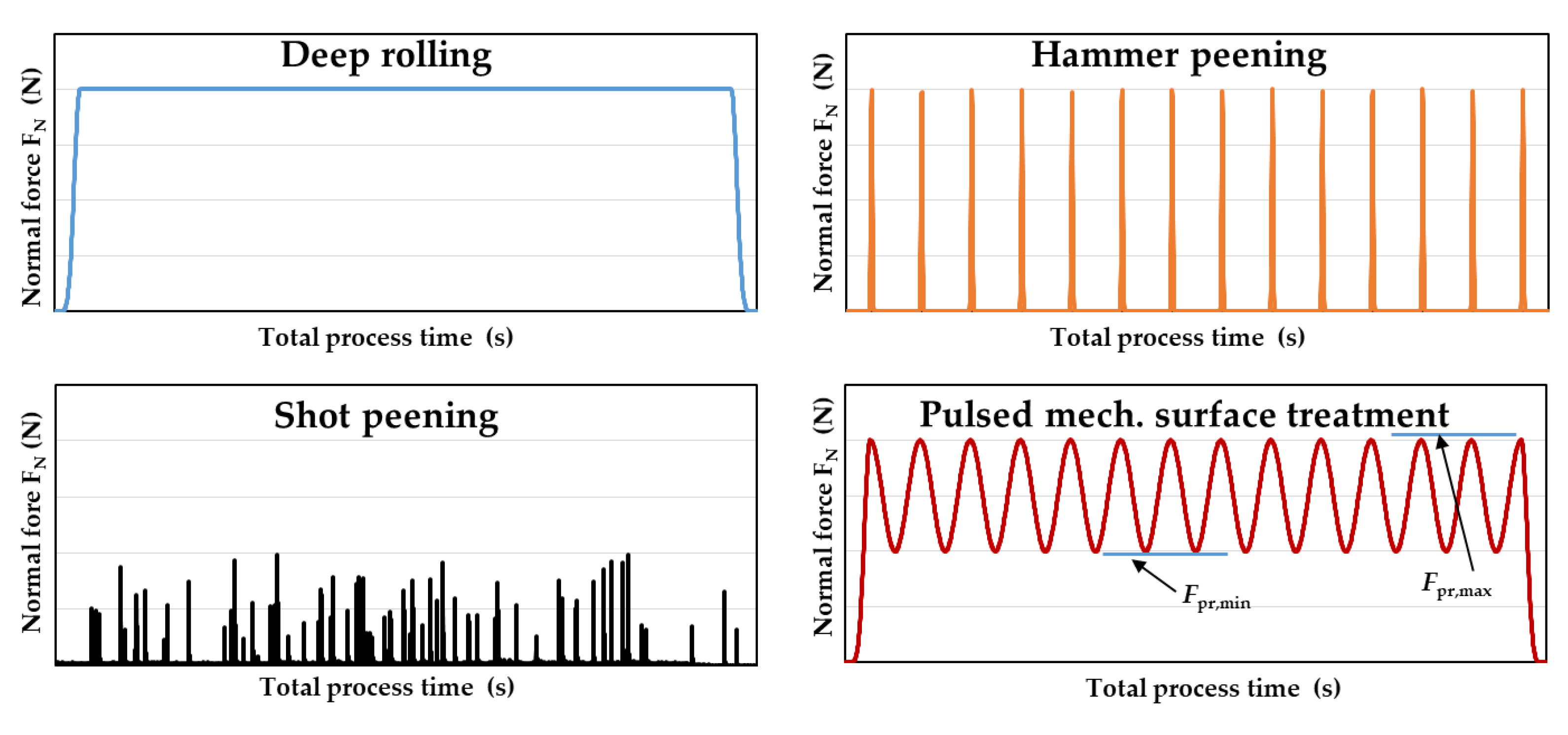
Figure 1 shows a time-based theoretical analysis of the occurring normal forces for deep rolling, shot peening, machine hammer peening, and PMST during the process. For deep rolling, the normal force (deep rolling force) is constant after an initial phase during the whole process and when using a hydrostatical deep rolling tool. The entire workpiece is influenced by the same force, based on the chosen process parameters. A process variation of conventional deep rolling is deep rolling with ultrasonic support as done in [11]. The frequencies used to induce the deep rolling process are in a significantly higher frequency range (multiple kHz) compared to the ones utilized during PMST (0.5 to 5 Hz). During shot peening, there are multiple force spikes visible in the diagram. Each of these spikes represents an impact generated by a single shot peening particle. Between these impacts, there is no additional influence on the workpiece. For shot peening, the processing of the workpiece is based on a statistical distribution since the impact location of an individual particle cannot be controlled exactly. Machine hammer peening is also composed of single mechanical impacts on the workpiece but reaches higher normal forces than shot peening and the single impacts occur regularly.
The last graph shows the estimated normal force-time sequence for a PMST process. After the process begins, the normal force alternates between a minimum force Fpr,min, and a maximum force Fpr,max. Compared to deep rolling, PMST also has a permanent normal force (Fpr,min, or higher) affecting the workpiece during the process although the amount of force is not constant during the process. Compared to shot peening, the workpiece is continuously affected by a normal force but there are also visible spikes (Fpr,max). Different to shot peening, this maximum force occurs on a geometrically specific spot of the workpiece which can be controlled by the process parameters.

1.2. Process Fundamentals

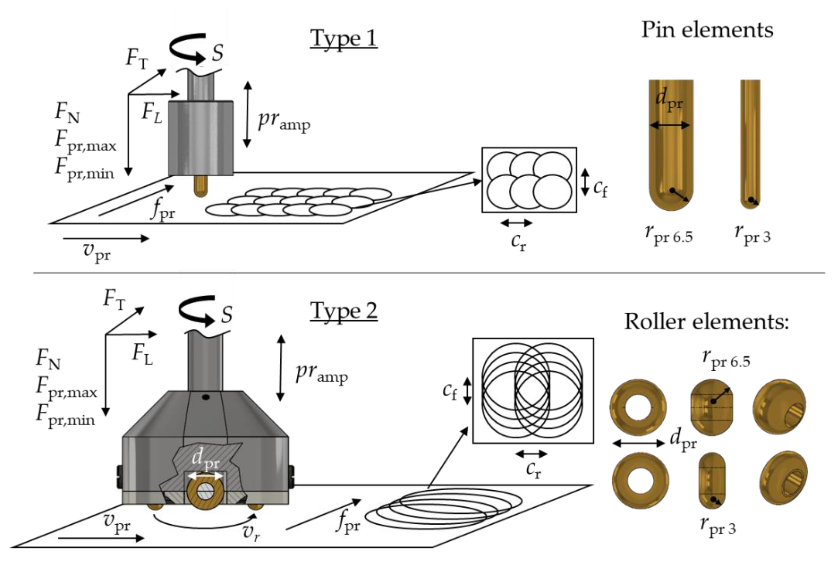
Experiments in this paper were performed as a path-controlled process. Process parameters were the radius of the tool rpr (mm), the minimum process normal force Fpr,min(N), the amplitude pramp (mm), and frequency f (1/s) for the strokes, as well as the process velocity vpr and the feed rate fpr (mm/min), which influence the offset between each stroke in processing direction cr (mm) and perpendicular to the processing direction cf (mm). Figure 2 gives an overview of these process parameters for the pulsed mechanical surface treatment.
As a first approach, two different types of PMST tools were developed. Type 1 is closely related to a burnishing process that uses carbide pin elements centered to the tool to generate single impacts on the surface while maintaining constant tool–workpiece contact and being routed over the surface. Tool type 1 does not roll over the surface in lateral and transversal directions but is rotating around its own axis. Type 2 uses roller elements that are arranged eccentric to the tool axis and therefore generate a pulsating rolling movement. In general, the kinematics of PMST type 1 are less complicated than type 2. Therefore, the experiments in this paper were conducted using type 1 to approach the concept and reach a stable process. The process for tool type 2 is characterized by a much more complex kinematic and will be examined systematically in further investigations. To generate a pulsed normal force, a MITIS® tool holder (by MITIS, Bouguenais, France) normally used for vibration drilling was utilized. This tool holder is used to create the amplitude and frequency of the strokes. It uses the tool revolutions supplied by the CNC manufacturing center to generate an additional stroke amplitude normal to the manufactured surface, thereby allowing the amplitude to be adjusted in the operating range of the tool holder. The frequency can be varied by choosing different tool holders but is fixed for each of them. The maximum process-normal-force Fpr,max is directly dependent on Fpr,min, and the chosen amplitude. For this setup, Fpr,max can only be determined based on experience.
The topography of the resulting surface and the location of each impact can be controlled by adjusting both offsets cf and cr. Therefore, the revolutions determine the total amount of strokes per minute when multiplied with the tool holder frequency. The total amount of strokes per minute multiplied with the process velocity and the process feed results in strokes per mm on the surface. The perpendicular feed fpr is equal to the offset cf. The depth of the impacts can be controlled with the chosen amplitude and the minimum process normal force Fpr,min. The relations between the different variables are also described by the equations in Table 2.

2. Materials and Methods

2.1. Material

The workpiece material analyzed within this work was S235. Its chemical composition is displayed in Table 3. After homogenization, the workpieces exhibited a hardness of 158 HV1. Heat treatment included heating up to 900 °C and holding this temperature for one hour. It resulted in a ferritic pearlitic microstructure (cf. Figure 11b). S235 was chosen in this state because of its lower hardness and good deformability. Both properties are beneficial for a first approach to a material-forming process like PMST.

2.2. Experimental Setup

As a basis for the experimental investigation, two different tool concepts were designed using a tool radius rpr of either 3 mm or 6.5 mm. Figure 3 shows both tool concepts.
For type 1, a fine-grain carbide (C: 10%, WC: 90%; Carbidur 902 by Carbidur AG, Benzstraße 6, 75210 Keltern-Dietlingen, Germany) pin is inserted in a base body made of 42CrMo4. The half-sphere contacting the workpiece has a radius rpr of either 3 mm or 6.5 mm. The tool is mounted in a MITIS® tool holder using a 12 mm mounting shaft at the top of the base body. Although the pin rotates around its axis, this process variant is called “static” in comparison to type 2 because there is no rolling motion on the specimen surface.
To integrate the rolling movement into the pulsed mechanical surface treatment, the second “dynamic” tool concept uses rollers (medium grain carbide of quality K30, supplied by Renzelmann Werkzeugtechnik GmbH, Bremen, Germany) running on small steel shafts. The steel shafts are mounted between a tool cover and the base body. Small flat head screws are used to secure these shafts. Spacers made of PTFE are used to center the rollers on the shafts. The base body is made of 42CrMo4 and up to two pairs of rolling spheres with two effective rolling diameters can be used.
To reduce friction, an 8% emulsion was used as a coolant for both tool concepts. While it was applied on the workpiece surface for type 1, for type 2, it was additionally supplied by the CNC machine center and transported to the spheres using a central coolant supply bore and individual cooling channels in the base body. All experiments were performed on a conventional 4-axis CNC machining center (DMC 65V by Deckel Maho, Pfronten, Germany); the whole experimental setup for the static tool, including a specimen, the MITIS® tool holder, and the measuring devices is shown in Figure 3.
The MITIS® tool holder (by MITIS, rue Johannes Gutenberg 12, 44340 Bouguenais, France) used for these experiments has an adjustable amplitude from 0.005 mm to 0.240 mm and a fixed stroke frequency of f = 1.5 per revolution. The amplitude pramp was set to 0.042 mm for all experiments performed. The tool holder was attached directly to the CNC manufacturing center, all tools were mounted directly in the tool holder.
As specimen metal plates made of S235 (1.0038, cf. Section 2.1) with dimensions of 120 × 150 × 25 mm are used. To minimize clamping errors and ensure a plane orientation of the machining center and the specimen, each plate was milled down by 0.2 mm (S = 800 (1/min); feed 500 (mm/min), cutting depth 0.1 (mm)) in the same clamping before usage. Figure 4 shows the surface characteristics after milling.

2.3. Measuring Devices

The process forces normal to the surface (FN), in as well as perpendicular to the processing direction, were measured utilizing a piezoelectric 3-component dynamometer (Typ 9257 B, Kistler Instrumente GmbH, Sindelfingen, Germany) equipped by a Kistler charge amplifier Typ 5019 A. A 500 Hz low pass filter was used to reduce the noise of the signal and the sampling rate was selected to 2500 Hz.
The analysis of the surface topographies (track as well as area) was carried out with the help of the Keyence digital microscope VHX—S 15 (KEYENCE DEUTSCHLAND GmbH, Neu-Isenburg, Germany). The images were captured with a 200x magnification.
The use and the coherence scanning interferometer Talysurf CCI HD (AMETEK GmbH, BU Taylor Hobson, Weiterstadt, Germany) enabled the determination of 3D images and Abbott curves.
Conventional hardness measurements (HV0.5) were performed for a depth up to 2 mm below the surface. In addition to that, universal micro hardness measurements were performed with the Fischerscope H100C testing device (Fischer Technology Inc., Windsor, CT, USA). Therefore, individual processed areas were separated by eroding. The samples were embedded, ground, and subsequently polished before testing on the cross-sections with a maximum indentation force of 10 mN. Starting at a distance to the surface of 6 µm, indentations were carried out at distances of approximately 15 µm. The measurements had a distance of approximately 100 µm parallel to the surface (cf. Figure 13).

3. Experimental Design and Parameter Variation

The experiments presented in this paper were performed to validate the process concept in general and to examine the influence of the process parameters on the resulting surface topography. Therefore, the process velocity vpr and the spindle speed S were varied over a wide range and in multiple combinations. The minimum process force was held constant at 125 N. Utilizing the tool type 1, experiments were performed as single track (feed = 0 mm) and area oriented (feed = varying) processes with a track length of 10 mm. The process parameters of all experiments are displayed in Figure 5. For each experiment, either the tool diameter, process velocity, or the spindle speed was varied. To account for outliers, all experiments were executed three times.

4. Results

4.1. Process Forces

The forces occurring during the process confirm the course theoretically assumed in Figure 1. Figure 6a exemplarily shows a force–time sequence for one 10 mm track out of the experiment with the experiment ID A7.
As expected, the normal force was pending between a minimum (Fpr,min) and a maximum (Fpr,max) normal force. Fpr,min was set to 125 N before the process began and was pending between 100 N and 140 N. The maximum normal force Fpr,max with a stroke amplitude of 0.42 mm was up to 950 N. The characteristic for the pulsed mechanical surface treatment presented in the work was the continuous contact between tool and workpiece due to a minimal normal force Fpr,min > 0 N. The transversal and latitudinal forces followed the same course after an initial starting period but were significantly lower than the normal forces (FTmax = 100 N, FLmax = 60 N).
As explained before, an increase in spindle speed leads to a higher stroke frequency, thus the effect of the different process parameters is visible comparing different force measurements. The maximum force can be easily adjusted by modifying the tool infeed.

4.2. Surface Properties

The interaction of the sinusoidal stroke generated by the rotation of the tool spindle and the process velocity is explained by the aid of individual tracks. The potential of the new process is then demonstrated utilizing different surface areas. A constant maximum stroke of 0.042 mm was used for all tests (corresponding forces: cf. Section 4.1).

4.2.1. Single tracks generated using tool type 1:

Figure 7 exemplarily shows the change of the track geometry with increasing process velocity vpr for a spindle speed S = 20 min−1 utilizing a tool with a radius of rpr = 3 mm. Individual indentations are highlighted by the dashed line. While a low velocity (vpr = 5 mm/min) led to a clear overlapping of the indentations, the center offset in the processing direction cr increased with increasing velocity. The indentations were almost separated at vpr = 15 mm/min.
Figure 8 shows the development of the center offset cr plotted against the spindle speed S (for two constant process velocities vpr = 25; 100 mm/min) and the process velocity (for a constant spindle speed S = 20 min−1) for both investigated tool sizes. As expected based on the theoretical values (blue), a quadratic increase of the center offset with a decreasing spindle speed as well as a linear increase of the center offset with increasing feed rate can be seen.
For a constant velocity (left side of Figure 8), center offsets slightly higher than the theoretical values were determined utilizing the smaller tool. Using the larger tool, values determined were below the theoretical center offsets.
For similar spindle speed, a larger center offset occurred at higher process velocities. The center offsets determined for both tool sizes show good agreement with the theoretical values in the range of low velocities. At higher velocities, the theoretical values lie between the center offsets determined for the small and the large tool. Differences between the results of both tool sizes that cannot be attributed to the process parameters may be explained by uncertainties in the determination of the offset.
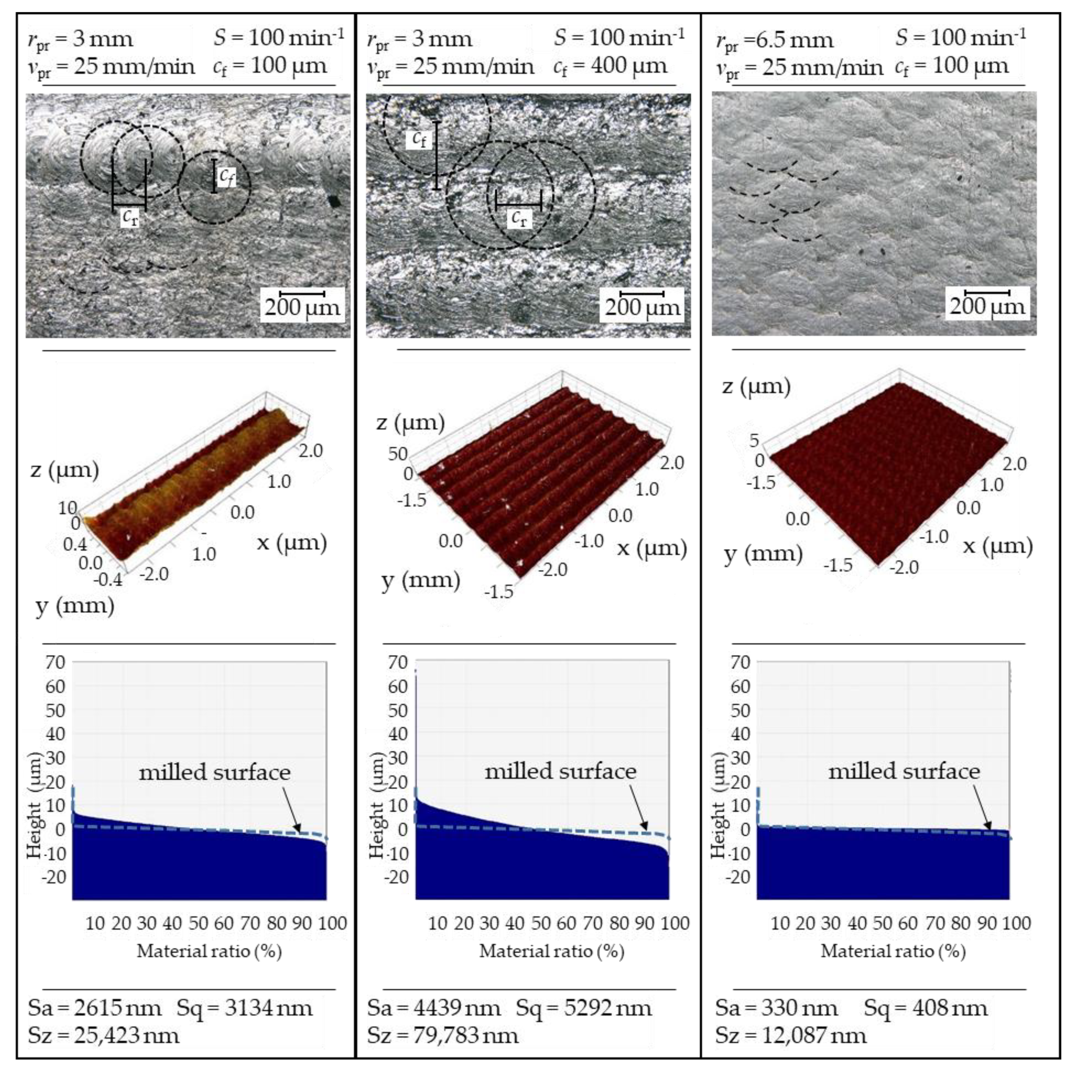
An offset perpendicular to the processing direction cf can be used to create an overlap of the resulting indentations (and tracks) and thus a deformed surface. The resulting surface topography depends on the spindle speed, the track offset in and perpendicular to the processing direction, and the tool diameter. Figure 9 exemplarily shows different two- and three-dimensional surface topographies, determined with a digital microscope and a coherence scanning interferometer respectively.

4.2.2. Areas Generated Using Tool Type 1

While individual indentations (although smaller in size due to the overlapping; dashed line) could still be identified in some areas on the left and middle column, the images in the right column show a scaly structure. Increasing the offset perpendicular to the processing direction (see left and middle column) led to a reduced overlapping of the individual tracks, which is why the indentations were easier to distinguish. Regarding the three-dimensional surface topography, a difference in height parallel to the tracks can be seen for the higher offset. The increasing height difference of individual profile areas with increasing offset is reflected in the roughness values determined. Compared to the milled surface (indicated by the dashed blue line), for which a Sa-value of 883 nm and an Sz-value of 23,301 nm were determined, higher surface roughness was obtained for the parameter combinations shown in the left and middle column. Offsets of 100 µm and 400 µm led to Sa = 2615 nm, Sz = 25,423 nm and Sa = 4439 nm, Sz = 79,783 nm, respectively.
The Abbott curves, additionally displayed in Figure 9, also show the different characteristics of the surface topography. The development of the material ratio in relation to the height of the profile is similar for the parameter combinations in the left and middle column but differs for low and high ratios and in the slope of the curve.
Using the larger tool (cf. right column of Figure 10), more material was being deformed. As the track number increased, the individual indentations could no longer be identified. Both two-dimensionally and three-dimensionally, it can be seen that the resulting surface had evenly distributed ups and downs. Compared to the milled state, the surface was characterized by lower roughness values (Sa = 330 nm, Sz = 12,087 nm). This coincides with the Abbott curve presented below, which shows high material ratios already at low profile heights.
Figure 10a shows the development of the roughness values Sa and Sz for an increasing offset perpendicular to the processing direction using the tool with a radius of 3 mm in combination with a process velocity of 25 mm/min and a spindle speed of 100 min−1. As indicated regarding the profiles plotted in Figure 10, an increasing offset leads to elevated surface roughness. The influence of rising feed rate and tool diameter on the surface roughness is shown for a constant offset of 100 µm in Figure 11b. For the same tool size, an increasing process velocity results in higher surface roughnesses. The larger tool reduces the surface roughness utilizing similar process parameters.

4.3. Subsurface Properties

For the evaluation of the process’s depth effect, microsections were prepared and HV 0.5 measurements were carried out. Figure 11a exemplarily shows the microstructure beneath a pulsed burnished surface (velocity of 50 mm/min, a track offset cf of 200 µm, and cr of 0.333 mm). Since a deformation was clearly visible for this parameter combination, a change in subsurface properties was assumed. The material shows a basic ferritic (white) and perlitic (grey) microstructure.
A deformation of the grain structure in the processing direction could be seen near to the surface. This was accompanied by an increase in hardness in and perpendicular to the processing direction, as shown in Figure 11b. Compared to the bulk material hardness an increase of approximately 70 HV0.5 could be observed at the surface. Bulk material hardness was reached at a distance of 1 mm to the surface. Considering the micrograph perpendicular to the processing direction, it becomes clear that the deformed grains close to the surface are not an effect of the pre-machining (milling) process. In the exclusively milled area, no or significantly less deformation of the microstructure was visible.
Due to the low material hardness, the standard-compliant HV0.5 hardness measurement only allows conclusions about the process effect at higher surface distances. To be able to place measurements both near the surface and at a smaller distance to each other, additionally instrumented microhardness measurements were performed. Compared to conventional hardness measurement methods, lower forces are applied in microhardness measurement and smaller volumes are taken into account. The resulting high influence of differences in microstructure or deformation degree on the values is counteracted by determining average values out of 10 measurement series placed parallel to the sample surface at intervals of 100 µm (cf. micrographs shown in Figure 13).
Figure 12 shows the determined hardness depth profiles parallel and perpendicular to the processing direction. Processing parameters were set to experiment ID A6 (cf. Figure 5). Independent of the process orientation, an increase in hardness due to pulsed mechanical treatment was observed. In contrast to the HV0.5 measurement, differences in hardness could be determined depending on the process orientation. Perpendicular to the processing direction, higher Martens hardness occurs near the surface. Compared to the hardness of the bulk material around 2200 HM the decrease in hardness was more pronounced perpendicular to the processing direction. The influence of pulsed mechanical surface treatment was dependent on the machining direction.
In order to assess the scattering of the values due to the processing as well as due to the microstructure, additional measurements were carried out parallel to the sample surface at a distance of z = 20 µm (orange) and z = 62 µm (gray). Hardness values determined parallel and perpendicular to the processing direction are plotted in Figure 13a,b. For both directions, the values determined in the different depths were above the bulk hardness. A periodic behavior due to pulsed processing could not be detected. The comparison of the two diagrams shows smaller value variations in the processing direction than perpendicular to it. In both figures, there are cracks visible on the photomicrograph at the intersection of the specimen material and the embedding material. These cracks could originate from the pre milling of the specimen, the pulsed mechanical surface treatment, or the preparation for the photomicrographs and will be further examined in future works.

5. Discussion

The results presented in Section 4 confirm the ability of the chosen experimental setup to superimpose a higher load on a constant load. Therefore, both the surface and the subsurface properties of the component can be influenced. Taking into consideration the resistant but still lubricious surface aimed at utilizing the presented new process, Abbott curves from Figure 9 (rdr = 3 mm; S = 100 min−1) were compared with the curve of the milled surface in Figure 14. The areas of high (1.) and low (2.) profile height are displayed in higher magnification.
Profile heights of around 10 µm already show a material ratio of approximately 10%. With decreasing profile height, the dark red curve shows a steeper increase in material ratio. Under load, 10% of the surface area is in contact at first and presumably deformed before the profile around 0 µm resists the load due to the higher material ratio. The maximum material ratio is reached at negative profile heights, which is due to the “downs” of the surface topography. These indentations could accommodate cooling lubricant. An ideally lubricatable surface should have only slight profile elevations but sufficient (in size and depth) indentations for the cooling lubricant. Since the presented pulsed mechanical surface treatment is a forming and not a subtractive process, indentations can only be created by deformation. Thus, the profile high increases at the same time. By variation of the process parameters, the surface could be adjusted, such that higher topography areas also show a higher material ratio and thus a higher resistance. The choice of a smaller tool could help to generate a flat Abbott curve in the area of slightly increased profile heights and a steeper slope in the area of negative profile heights.
To enable a quantification of the influence of the process parameters, on the right side of Figure 14, the areal material ratios Smr1 and Smr2 are additionally displayed. Since an increase in surface roughness is achieved by choosing higher center offsets and results in separated indentations, a decrease in the areal material ratios is expected for increasing center offsets.
Almost independent of the center offset, Smr1 values were around 10%. While an Smr1 value increasing from 10 to 13% was visible for an increasing center offset at a velocity of 50 mm/min, a slight decrease from 14% to 8% could be seen at first before the values increased up to 20% at a velocity of 25 mm/min. Smr2 was above 88% for all parameter combinations. For both velocities, Smr2 first decreased before reaching its highest value.
Due to the increase in hardness of the surface and subsurface area associated with the plastic deformation (cf. Figure 11 and Figure 13), it can be assumed that the higher profile areas also offer increased resistance to wear. The actual behavior of the surfaces generated by a pulsed mechanical surface treatment in different applications must, therefore, be examined.

6. Conclusions and Outlook

The main aspect of this paper is the presentation of a new manufacturing process to generate geometrically defined surfaces with functional properties and a positively influenced surface and subsurface layer. The process, therefore, is characterized by a constant tool–workpiece contact and a continuous normal force affecting the surface. This normal force alternates between a minimum and a maximum value, depending on the process parameters. Two different processes with two tool types (1 and 2) were successfully designed. Tool type 1 was implemented and tested with two different tools sizes. The resulting surface topography was directly correlated to the process parameters and therefore could be designed for specific purposes like holding a specific amount of lubricant while still having a mechanically enhanced surface and subsurface layer.
This could be used to enhance the lifetime of highly stressed parts like ship propellers which are exposed to high mechanical punctual loads due to cavitation during their service life. A hardened, structured surface could minimize the occurring cavitation and improve the resistance of the parts against mechanical loads. Other applications could be hardened surfaces which are structured and optimized for aerodynamic purposes or fluid transport. A structured surface could improve the friction between the fluid and pipe walls or minimize fluid turbulences.
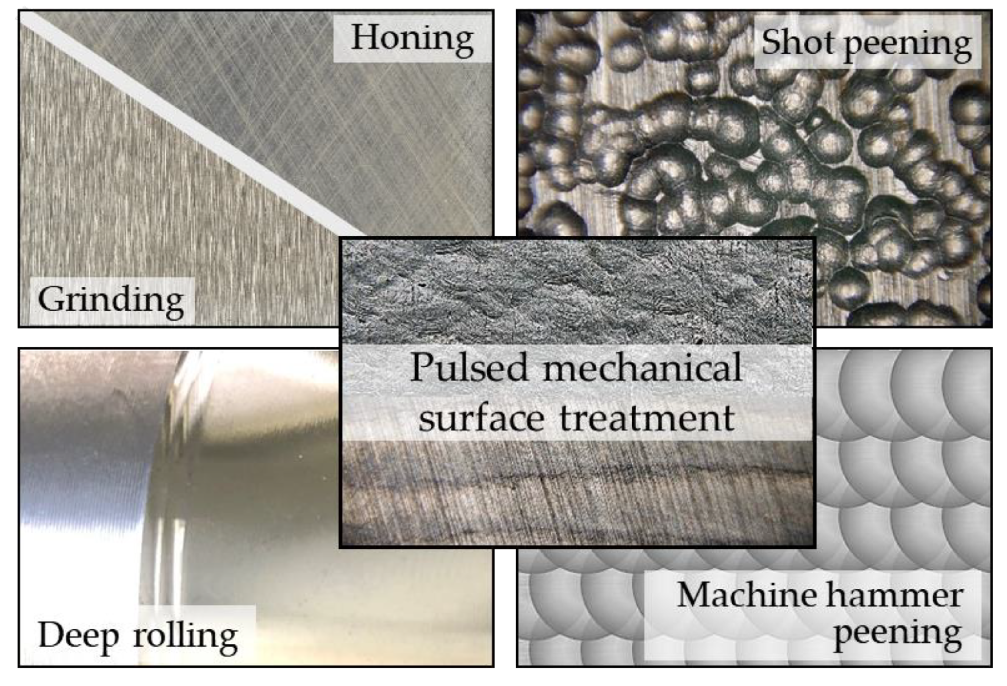
The process can be classified between other processes which generate final functional surfaces like honing, grinding, deep rolling, shot peening, or machine hammer peening. Figure 15 gives a quick overview of the resulting surfaces of each of these processes and the classification of pulsed mechanical surface treatment. In addition to a geometrically defined surface topography, the process resulted in a general increase of hardness in the surface and subsurface layer of about 300 HM with spikes up to 1800 HM higher than the bulk material. The results are promising and indicate a high potential for PMST to be evaluated in further investigations.
In addition to the experiments with tool type 1, a first approach was also made to implement the process with the tool type 2. Only selected parameter combinations were used based on experiments performed with tool type 1. Results presented in the following were generated with a spindle speed S of 100 (1/min) and process feeds fpr of 25 or 50 (mm/min). This resulted in a rolling speed vr of 11 (m/min).
The experiments performed resulted in surfaces characterized by overlapping circular tracks as shown exemplarily in Figure 16. Due to the rotating tool movement and the forces (in processing direction and perpendicular to the processing direction), the influence on the workpiece was much more complex. The feed force chosen in the presented example resulted in almost parallel rolling tracks in the upper and lower section, which varied in their track depth depending on the pulsed lift-off of the tool. In the area of track overlay (enlarged right red marked picture), multiple rollovers of the tool occurred in a single spot. These multiple rollovers could generate different properties in the surface and subsurface area, which will be investigated in further research.
Following the current work, tests with higher rolling forces and thus more pronounced plastic deformations will be carried out for a more detailed analysis of the surface topography.
The conducted experiments showed that the process is challenging to implement. Although the measured forces, offsets, and feeds met the calculated values the use of a mechanical tool holder to implement the pulsating movement leaves room for improvement. In a highly dynamic industrial environment, variables such as the stroke amplitude could be useful as a quick adjustable process parameter. Moreover, the maximum normal force which could only be determined experimentally in this research should be a controlled process parameter to maximize the possible benefits of PMST. These improvements could be achieved when instead of the mechanical MITIS tool holder, a magnetic beared and controlled tool spindle (by, e.g., KEBA AG, Linz, Austria) is used.
Further research will deal with of the process itself, such as the complex kinematics of the rolling process (type 2) when manufacturing bigger, overlapping areas, the possible amount of the minimum normal force Fpr,min, and the possible dynamic of the process will be addressed. In addition, further investigations on other surface and subsurface properties such as resulting residual stresses will be conducted.
Author Contributions

Conceptualization, investigation, and writing—original draft preparation, M.H. and N.M.; supervision and writing—review and editing, D.M. All authors have read and agreed to the published version of the manuscript.

Funding

This research was funded by the German Research Foundation (DFG).

Data Availability Statement

The data presented in this study are available on reasonable request from the corresponding author.

Acknowledgments

The authors thank Helge Decho for performing the instrumented microhardness measurements and his support in the evaluation of the results. Financial support of the subproject U04 “Mechanical Treatment” of the Collaborative Research Center CRC 1232 by the Deutsche Forschungsgemeinschaft (DFG, German Research Foundation)—project number 276397488—SFB 1232 is gratefully acknowledged. The authors would like to thank the German Research Foundation (DFG) for funding the projects HE 3276/7-1 and ZA 288/64-1: “Distortion Engineering during Grinding by computer-aided Design of Distortion Compensation Strategies”.

Conflicts of Interest

The authors declare no conflict of interest.

Nomenclature

cf(µm)Track offset (perpendicular to the processing direction)
cr(µm)Track offset (in processing direction)
S(1/min)Spindle speed
fpr(mm/min)Feed rate
FN(N)Process normal force
FT(N)Transversal force
FL(N)Lateral force
Fpr,min(N)Minimum PMST normal force
Fpr,max(N)Maximum PMST normal force
rpr(mm)Radius of the tool
pramp(mm)PMST amplitude
f(1/s)PMST frequency
vpr(mm/min)PMST process velocity
vr(m/min)Rolling speed
dpr(mm)Total tool diameter
Strmin (1/min)Strokes of the tool per min
Strmm(1/mm)Strokes of the tool per mm

References

  1. Wiens, A. Formhonen von Zylinderlaufbahnen. Ph.D. Thesis, Technical University of Braunschweig, Braunschweig, Germany, 2011. ISBN 9783802783159. [Google Scholar]
  2. Flores, G. Honen: Grundlagen und Anwendungen; VDI-Verlag: Düsseldorf, Germany, 1992; ISBN 9783184010881. [Google Scholar]
  3. Große, T. Formhonen Mit Piezo-Hydraulischem Honwerkzeug. Ph.D. Thesis, Technical University of Braunschweig, Braunschweig, Germany, 2016. [Google Scholar]
  4. Schulze, V. Modern Mechanical Surface Treatment: States, Stability, Effects; Wiley-VCH Verl.: Weinheim, Germany, 2006; ISBN 3-527-31371-0. [Google Scholar]
  5. Schulze, V.; Bleicher, F.; Groche, P.; Guo, Y.B.; Pyun, Y.S. Surface modification by machine hammer peening and burnishing. CIRP Ann. 2016, 65, 809–832. [Google Scholar] [CrossRef]
  6. Lu, H.; Scholtes, B.; Macherauch, E. Randschichtzustände von normalisiertem und vergütetem 42 CrMo 4 nach konsekutiven Kugelstrahl- und Festwalzbehandlungen. Mater. Und Werkst. 1992, 11, 388–394. [Google Scholar] [CrossRef]
  7. Garbrecht, M. Mechanisches Randschichthärten in der Fertigung; University of Bremen: Bremen, Germany, 2006. [Google Scholar]
  8. Schulze, V.; Hoffmeister, J. Mechanische Randschichtverfestigungsverfahren: Verfahren. In Handbuch Wärmebehandeln und Beschichten, 1st ed.; Spur, G., Ed.; Carl Hanser Fachbuchverlag: München, Germany, 2015; ISBN 9783446430037. [Google Scholar]
  9. Broszeit, E. Grundlagen der Schwingfestigkeitssteigerung durch Fest- und Glattwalzen. Mater. Werkst. 1984, 15, 416–420. [Google Scholar] [CrossRef]
  10. Delgado, P.; Cuesta, I.I.; Alegre, J.M.; Díaz, A. State of the art of Deep Rolling. Precis. Eng. 2016, 46, 1–10. [Google Scholar] [CrossRef]
  11. Wang, G.Q.; Zhu, X.P.; Lei, M.K.; Guo, D.M. Inverse surface integrity problem in ultrasonic impact-treated AISI 304 stainless steel components. Int. J. Adv. Manuf. Technol. 2016, 87, 2033–2040. [Google Scholar] [CrossRef]
  12. Denkena, B.; Krödel, A.; Heikebrügge, S.; Meyer, K.; Pillkahn, P. Surface topography after deep rolling with milling kinematics. Prod. Eng. Res. Dev. 2021, 15, 587–593. [Google Scholar] [CrossRef]
  13. Klotz, T.; Delbergue, D.; Bocher, P.; Lévesque, M.; Brochu, M. Surface characteristics and fatigue behavior of shot peened Inconel 718. Int. J. Fatigue 2018. [Google Scholar] [CrossRef]
  14. Feldmann, G.; Wong, C.C.; Wei, W.; Haubold, T. Application of Vibropeening on Aero—Engine Component. Procedia CIRP 2014, 13, 423–428. [Google Scholar] [CrossRef] [Green Version]
  15. Gopinath, A.; Chan, W.L.; Kumar, A.S. Data Driven Optimization of Vibropeening. Procedia CIRP 2020, 87, 285–290. [Google Scholar] [CrossRef]
  16. Kolouch, M.; Wabner, M.; Kurth, R. Hammer Peening with A Piezo-Actuated Tool For Surface Finishing. MM Sci. J. 2017, 2017, 2055–2062. [Google Scholar] [CrossRef]
  17. Bleicher, F.; Lechner, C.; Habersohn, C.; Obermair, M.; Heindl, F.; Rodriguez Ripoll, M. Improving the tribological characteristics of tool and mould surfaces by machine hammer peening. CIRP Ann. 2013, 62, 239–242. [Google Scholar] [CrossRef]
  18. Adjassoho, B.; Kozeschnik, E.; Lechner, C.; Bleicher, F.; Goessinger, S.; Bauer, C. Induction of residual stresses and increase of surface hardness by machine hammer peening technology. In Annals of DAAAM for 2012 & Proceedings of the 23rd International DAAAM Symposium; Katalinic, B., Ed.; DAAAM International: Vienna, Austria, 2012; ISBN 978-3-901509-91-9. [Google Scholar]
  19. Bleicher, F.; Lechner, C.; Habersohn, C.; Kozeschnik, E.; Adjassoho, B.; Kaminski, H. Mechanism of surface modification using machine hammer peening technology. CIRP Ann. 2012, 61, 375–378. [Google Scholar] [CrossRef]
Figure 1. Theoretical comparison of time-based normal forces for four different processes with a mechanical main effect.
Jmmp 05 00098 g001
Figure 2. Parameters of pulsed mechanical surface treatment.
Jmmp 05 00098 g002
Figure 3. Experimental setup (left) and details of the used tools type 1.
Jmmp 05 00098 g003
Figure 4. Surface characteristics of the milled surface.
Jmmp 05 00098 g004
Figure 5. Experimental setup for experiments using tool type 1, the used process parameter to vary the offset cr is marked blue.
Jmmp 05 00098 g005
Figure 6. (a) Normal force (experiment ID: A7), (b) comparison of normal forces at varied spindle speed (zoomed extract of the force measurement of the experiments with the IDs T23 and T24).
Jmmp 05 00098 g006
Figure 7. Track geometry resulting for various process velocities (tool diameter rpr = 3 mm, spindle speed S = 20 min−1).
Jmmp 05 00098 g007
Figure 8. Influence of various spindle speeds S (left) and process velocity vpr (right) on the center offset cr.
Jmmp 05 00098 g008
Figure 9. Microscopic surfaces (top), coherence scanning interferometer surfaces (middle), and Abbott curves (bottom) for the conducted PMST experiments with varied tool sizes and track-offset cf.
Jmmp 05 00098 g009
Figure 10. Influence of (a) the center offset, (b) the tool size and the process velocity on the surface roughness (filled beam: vpr = 25 mm/min, striped beam: vpr = 50 mm/min).
Jmmp 05 00098 g010
Figure 11. (a) Microstructure underneath a pulsed mechanically treated surface in comparison to the initial milled state, (b) corresponding HV0.5 measurement for specimen after processing with type 1.
Jmmp 05 00098 g011
Figure 12. Hardness depth profiles determined utilizing microhardness measurements.
Jmmp 05 00098 g012
Figure 13. Hardness values determined in various distances z to the surface by instrumented microhardness measurement: (a) in processing direction; (b) perpendicular to processing direction. Experiment ID = A6.
Jmmp 05 00098 g013
Figure 14. Comparison of Abbott curves generated by milling and pulsed mechanical surface treatment.
Jmmp 05 00098 g014
Figure 15. Different resulting surface topographies for grinding, honing, shot peening, deep rolling, machine hammer peening (exemplary), and classification of pulsed mechanical surface treatment. (Pictures by IWT Bremen).
Jmmp 05 00098 g015
Figure 16. Surface geometry of a pulse rolled area resulting for S = 100 (s/min) and fpr = 25 (mm/min).
Jmmp 05 00098 g016
Table 1. Common finishing processes and their influence on surface and subsurface properties (cf. e.g., [1,4,17].).
ProcessCharacteristicsMaterial Removing ProcessForming ProcessContinuous Contact to WorkpieceConstant Force Affecting the
Workpiece
Statistically Distributed ImpactsMultiple Deformations of the
Same Area
Defined Impact PositionSurface PropertiesFunctional SurfaceSmooth SurfaceSurface with Single ImpactsGeometrically Defined SurfaceSubsurface PropertiesBased on the Process
Settings from Compressive
Residual Stresses to Tension
Residual Stresses
Compressive Residual Stresses
(Low Depth Effect)
Compressive Residual Stresses
(High Depth Effect)
Honing
Grinding
Deep rolling
Shot peening
Machine hammer peening
Pulsed mechanical surface treatment
Table 2. Equations and relations for cf and cr.
Strokes Per Minute StrminStrokes Per mmStrokes Per mm2cr/cf
Strmin = S × Fcf × Strmin = StrmmStrmm × cr = Strareacr = vpr/cf = fpr;
Table 3. Chemical composition of the material used for the experimental work.
MaterialChemical Composition in ma.%
CSiMnPSCrMoNiCuNCoVTiAsSn
S235JR (1.0038)0.0780.190.570.0140.0130.190.0620.20.210.0160.01<0.010.0240.0070.011
Publisher’s Note: MDPI stays neutral with regard to jurisdictional claims in published maps and institutional affiliations.