Abstract
Friction stir welding (FSW) has been proposed as an alternative modern joining technology and demonstrated important benefits for the manufacturing of efficient and lightweight aircraft structures using high-strength aluminium alloys. These structures are required to be corrosion- resistant and thus, it is necessary to use technologies such as surface treatments and sealants in their manufacturing and assembly. In this work, the feasibility of combining innovative Cr-free surface treatments, sealants and FSW technology was investigated with the focus on the durability of the joints in fatigue. FSW lap joints were produced using AA2099-T83 extrusions and AA2060-T8E30 sheets in the as-received or surface-treated condition. A sealant was also applied in some cases at the overlapping interface before the FSW process. Static tensile tests and fatigue tests were carried out applying hoop-stress loading conditions. Different fracture modes were identified depending on the stress levels applied in the fatigue tests: High stress levels resulted in fractures in the HAZ of the FSW joints, while the specimens tested at low stress levels showed fractures out of the FSW joint. In general, FSW joints produced using surface-treated aluminium components and sealant presented improved fatigue life and extended durability in comparison with non-treated aluminium joints. The surface treatments and sealant at the interface of AA2099-T83 extrusions and AA2060-T8E30 sheets reduced the friction and local damage produced due to the sliding movement during the fatigue tests, minimizing the fretting fatigue effect, which was found to be the main limiting factor on the durability and fatigue life of the FSW joints.
1. Introduction
Aircraft structures are usually manufactured using high-strength aluminium alloys, such as 2xxx and 7xxx series, due to their good mechanical performance: low density, high stiffness, corrosion resistance, fracture toughness and fatigue growth resistance [1]. However, the difficulties in welding these alloys by conventional fusion welding processes has limited the possibilities for an efficient manufacturing, opening a new research field for the use of alternative joining technologies based on solid-state processes. One of the most recognized solid-state joining processes for high-strength aluminium alloys is friction stir welding (FSW) [2,3,4,5]. FSW has been successfully used as an alternative to riveting in aircraft structural components for joining precipitation-hardening aluminium alloys such as 2024-T3 [6], 7075-T6 [7] and even dissimilar joining 2024-T3 to 7075-T6 alloys [8].
Another important issue to be considered for the design and manufacturing of aircraft structures such as fuselage panels is the corrosion resistance, since this is essential for a long-term operational capability. In order to achieve this using aluminium alloys, a great variety of corrosion protection methods exist, such as surface treatments and sealants. For the adequate selection of these protection methods, it is important to consider the operational considerations, societal concerns and REACH regulations [9], which are creating a growing demand for the development of new effective and environmentally friendly surface treatment technologies. In addition to this, there is a continuous need to reduce the environmental footprint of the manufacturing technologies, as established in the ACARE targets [10]. Thus, the materials employed in the manufacturing of current and future aircraft structures need to become more resistant to corrosion and, at the same time, more eco-compliant to achieve an environmentally friendly life cycle [11]. This implies a significant decrease in hazardous materials for their manufacturing. In this context, chrome-free surface treatments such as thin film sulphuric acid anodizing (TFSAA) and out-of-bath sprayable Sol-Gel application play an important role as a replacement for conventional anticorrosive protection processes using chromates [12].
The need to combine surface treatments, sealants and joining technologies is a continuous challenge in the manufacturing of structures such as reinforced fuselage panels. In fact, several authors investigated the feasibility of FSW and its derivatives such as refill friction stir spot welding (RFSSW) for joining surface-treated aluminium alloys in the overlap configuration using sealants [13,14,15,16,17]. These studies showed a promising potential of FSW technologies to join surface-treated aluminium alloys using sealants in appropriate welding conditions. In one of our previous works, the feasibility for FSW surface-treated AA2099-T83 aluminium extrusions with AA2060-T8E30 aluminium sheets in the overlap configuration using a sealant at the interface was investigated [18]. The new Cr-free surface treatments TFSAA and Sol-Gel were applied to the parent materials and the static behavior by pull-out tests was investigated, showing that these corrosion protection methods had no significant effects on pull-out static mechanical properties.
The fatigue behavior of representative FSW joints used for the manufacturing of fuselage panels has been investigated [19,20,21]. L. Dubourg et al. [20] optimized the FSW process and the mechanical properties of friction stir lap welds of 7075-T6 stringer on 2024-T3 skin, focusing on the defects associated with this joint configuration, such as top-sheet thinning, voids, hooking and kissing-bonds. H. J. Schmidt et al. [21] investigated the crack scenarios and crack growth rates in integral structures and built-up structures of fuselage panels with FSW joints. However, although it is extremely significant, the fatigue performance of FSW joints combined with surface treatments and sealants has not been investigated previously.
Thus, the present work is focused on investigating the fatigue behavior of FSW joints produced using surface-treated high-strength aluminium alloys with sealant application and comparing their properties with FSW joints produced using non-treated alloys. At this point, the analysis of fatigue behavior of welded joints, it is important to highlight the significant contribution that infrared (IR) thermography methods can make, allowing us to study the location of the failure area in real time. Thermography methods have been satisfactorily employed to assess the fatigue behavior and the damage evolution of materials and their welded components [22,23,24].
2. Experimental Procedure
2.1. Materials and Surface Treatments
Z-shaped extrusions of AA2099-T83 aluminium alloy as stringers and rolled sheets of AA2060-T8E30 aluminium alloy as skins were used to manufacture the stringer-skin lap joints. Both alloys belong to the third generation of aluminium–lithium (Al-Li) alloys that present excellent properties such as high strength, low density and excellent corrosion resistance. The thickness of the AA2099-T83 stringers was 2 mm, while the thickness of the AA2060-T8E30 skins was 2.5 mm. The nominal chemical compositions of the stringer and skin aluminium alloys are shown in Table 1.

Table 1.
Chemical composition of base materials, wt %.
Before FSW, skins and stringers were subjected to different combinations of surface treatments as well as sealant application at the matching interface. Table 2 summarizes the welded coupons and their surface conditions before the FSW process.
Table 2.
FSW coupon identification with the applied surface treatments and sealant.
TFSAA and Sol-Gel (AC131 from 3M) surface treatments, which are fully chromium-free and REACH compliant, were applied by the Hellenic Aerospace Industry S.A. (HAI). For more information on the composition of the surface treatments and sealant and how they were applied on the stringers and skins, the readers are referred to a previous work of the authors [18].
2.2. Friction Stir Welding Procedure
The Z-shaped AA2099-T83 stringers and the AA2060-T8E30 skins were friction stirwelded at LORTEK in the overlap configuration in an I-STIR PDS 4 machine operated in force control. 500-mm-long stringers were friction stir welded in the central position of 600-mm-long and 200-mm-wide skins. The FSW tool (Figure 1a) consisted of a probe with three flats and a mixed thread with a diameter of 4 mm and a length of 2.5 mm. The shoulder had a flat shoulder of 10 mm in diameter. The fixtures and clamping system used for the positioning and clamping of the Z-shaped stringer on top of the skin are shown in Figure 1b.
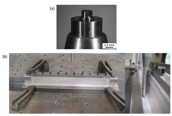
Figure 1.
(a) FSW tool and (b) Setup for the FSW process.
All coupons were produced using the same FSW parameters at a clockwise rotational speed of 1200 rpm, a welding speed of 250 mm/min, and a forge force of 6.25 kN. The tilt angle of the tool was 1.5° in all cases. The selection of these FSW parameters was based on the optimization study performed by the authors in one of our previous works [2]. The advancing side of the welds was oriented towards the vertical section of the extrusions and the retreating side towards the free edge.
2.3. FSW Joint Characterisation
The FSW coupons C01-C06 were characterised by metallographic characterisation, microhardness measurements, static tensile tests and fatigue tests under hoop-stress loading conditions. In this loading condition, tensile stresses are applied to the AA2060-T8E30 skin as is shown by the red arrows in Figure 2.
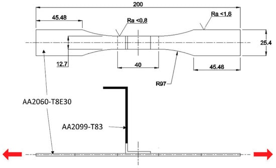
Figure 2.
FSW specimens machined from the coupons used for the static tensile and fatigue tests under hoop-stress loading conditions (indicated by the red arrows).
For the metallographic characterisation, cross-sectional specimens were cut perpendicular to the welding direction from each of the welded coupons. The specimens were prepared using standard procedures for mounting, grinding, and polishing to a mirror-like surface finish using a colloidal silica suspension. After this preparation, the specimens were etched using a diluted Keller’s reagent to reveal the microstructure. The initial metallographic examination of the cross-sectional specimens was performed by optical microscopy using an Olympus GX51 light optical microscope. Hardness measurements were made using the Vickers hardness scale with a sampling step of 0.5 mm and a load of 5 N applied for 15 s.
Specimens for static tensile tests and fatigue tests were prepared following the recommendation by the BS EN 6072 standard. 30-mm-wide specimens were cut from the welded coupons using electrical discharge machining (EDM) and final mechanical milling was applied to achieve the final geometry. The geometry of the final specimens is shown in Figure 2. For the static tensile tests, a Zwick Roell Z100 tensile testing machine with a load capacity of 100 kN was used at a constant testing speed of 1.6 mm/min. The fatigue behaviour of the FSW joints was studied by fatigue strength data as represented in basic S-N diagrams. The fatigue performance was evaluated using an MTS hydraulic testing machine. Fatigue tests were conducted in load control, using a sinusoidal waveform at 10 Hz and R = 0.1. Fatigue stress levels among 15–70% of the AA2060-T8E30 base material’s yield strength were applied as hoop-stress loading on the AA2060-T8E30 skin. During the fatigue tests, an IR camera (model FLIR A655sc series) was employed to record the temperature field evolution on the surface of the specimens. Optical field-of-view conditions were achieved by installing the camera at a distance of approximately 0.5 m between specimens and the lens of the camera. After finishing the fatigue tests, the fractured specimens were examined using scanning electron microscopy (SEM) as well as energy dispersive spectroscopy (EDS) to determine the fatigue crack behaviour and the influence of the weld microstructure and surface conditions on the nucleation site.
3. Results
3.1. Static Tensile Tests
Static tensile tests were performed under hoop-stress loading conditions with specimens machined from coupons C01–C06. Two specimens from each coupon were tested showing very similar results. A summary of the obtained results can be observed in Figure 3a. Very similar yield stress and UTS values were obtained for all specimens showing no significant influence of the surface treatments and sealant application in the performance of the FSW joints. Yield strength values between 410–424 MPa were obtained showing a minor variability of approximately 3% among all tested specimens. In terms of UTS, a variability of approximately 2% was observed with values between 486–498 MPa. All specimens showed an equivalent fracture mode with an initiation in the HAZ and propagation at 45° through the AA2060-T8E30 skin as shown in Figure 3b.
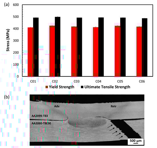
Figure 3.
(a) Yield strength and ultimate tensile strength values obtained for specimens machined from C01–C06 and (b) metallographic cross-section of a fractured C01 (non-treated without sealant) specimen showing the fracture initiation at the HAZ.
The initiation of the fracture in the HAZ can be explained by the hardness reduction of the AA2060-T8E30 base material in this zone, in addition to the coincidence with the lowest effective thickness of the AA2060-T8E30 sheet in the close vicinity of the FSW joint. Figure 4 shows the microhardness values obtained for the AA2060-T8E30 alloy in a scan of indentations performed parallel to the interface between the AA2060-T8E30 sheet and the AA2099-T83 stringer (A–B line in Figure 4a). Although the lowest values of approximately 110 HV0.5 were obtained in the stir zone (SZ), the larger effective thickness provided by the FSW joint in this zone compensates for the lower strength avoiding the fracture through the SZ. The hardness increases to values in the range of 120–130 HV0.5 in the HAZ of the advancing and retreating sides, where the effective thickness of the AA2060-T8E30 sheet decreases to its minimum value of 2.5 mm. Thus, the fracture is initiated in the region where the thickness is the lowest and the hardness values are still significantly low in the HAZ of the FSW joints.
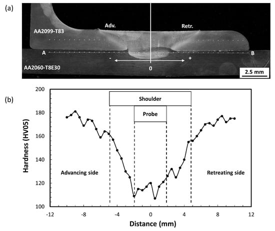
Figure 4.
(a) Metallographic cross-section of a specimen obtained from coupon C01 and (b) microhardness scan measurements in the A–B line shown in Figure 4a.
3.2. Fatigue Tests
Basic S-N curves were obtained for the FSW joints machined from the C01–C06 coupons after the fatigue tests carried out under dynamic hoop-stress loading conditions. Several comparative analyses of the S-N curves are presented in Figure 5, Figure 6 and Figure 7, where the stress level in the y axis is represented as a percentage of the yield strength of the base material.
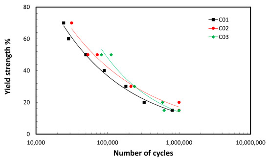
Figure 5.
S-N curves of FSW joints showing a comparison between FSW specimens produced with bare aluminium alloys (C01) and surface-treated aluminium alloys without sealant (C02 and C03).
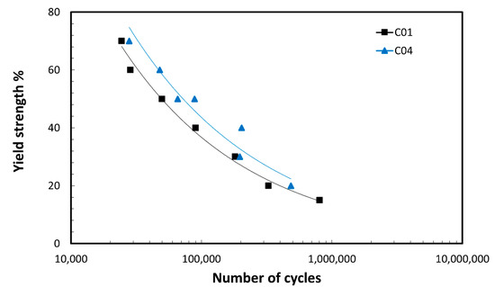
Figure 6.
S-N curves of FSW joints showing a comparison between FSW specimens produced with bare aluminium alloys without sealant (C01) and with sealant (C04).
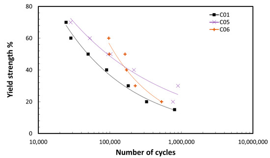
Figure 7.
S-N curves of FSW joints showing a comparison between FSW specimens produced with bare aluminium alloys without sealant (C01) and surface-treated aluminium alloys with sealant (C05 and C06).
Figure 5 shows the comparison between the FSW joints produced using bare aluminium alloys (C01) and those produced using surface-treated aluminium alloys, TFSAA in C02 and Sol-Gel treatment in C03. According to these results, surface-treated FSW joints obtained from C02 and C03 showed a slightly better fatigue behavior and extended life compared to the FSW joints obtained from the coupon C01. A similar conclusion can be obtained from the results shown in Figure 6, where the fatigue life of FSW joints obtained from coupon C01 is compared to the ones produced using the same bare aluminium substrates, but sealant in the stringer-skin interface prior to FSW (coupon C04). The fatigue specimens containing sealant showed a better fatigue performance and durability in comparison with the reference FSW joints from coupon C01. Figure 7 shows the comparison between the reference FSW joints machined from coupon C01 and those obtained from the coupons produced using a combination of surface-treated aluminium alloys and sealant in the stringer-skin interface, coupons C05 and C06. Once again, the FSW joints containing surface treatments and sealant showed a longer fatigue life than the reference FSW joints. According to these results it could be stated that both the use of surface-treated aluminium alloys and the application of sealant improved the fatigue life of the FSW joints, when they are applied either in an individual or a combined way.
The fracture analysis of the FSW joints in the fatigue tests allowed us to distinguish two main fracture modes as shown in the S-N data represented in Figure 8. The specimens tested in high-stress loading conditions showed failures at a relatively low number of cycles with a fracture initiation and propagation in the HAZ of the FSW joint (indicated in red in Figure 8). On the other hand, the specimens tested in low-stress loading conditions presented a higher number of cycles until fracture and they showed a fracture located out of the FSW joint (indicated in blue in Figure 8). This type of failure could be related to fretting fatigue phenomena [25,26] occurring at random locations in the contacting stringer-skin interface out of the FSW joints, generating an initial damage and fracture initiation point for a later fracture out of the FSW joint.
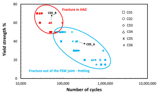
Figure 8.
S-N data of FSW joints showing different fracture modes in high- and low-stress loading conditions.
The monitoring of the FSW specimens during the fatigue tests by IR thermography allowed us to capture the instants when the fracture occurred for the two different failure modes identified (Figure 9). The positions of the AA2099-T83 stringer, the AA2060-T8E30 skin and the FSW joint were highlighted with black lines for a better clarity of the images. The image in Figure 9a shows the instant when the fracture of the specimen C05_A, which was tested at relatively low stress conditions as indicated in Figure 8, occurred. It can be clearly observed that the fracture initiation and final fracture occurred out of the FSW joint after 216,817 cycles. On the other hand, the image in Figure 9b shows the instant of the fracture of the specimen C05_B, tested in high-stress loading conditions (Figure 8). It can be observed that the fracture occurs in the HAZ of the FSW joint after 52,306 cycles. Although it was not possible to achieve an accurate quantification of temperature variations during the fatigue tests, IR thermography allowed us to clearly distinguish the fracture initiation points. Thus, IR thermography was found to be an effective technique to carry out qualitative studies in the fatigue tests of FSW joints.
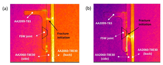
Figure 9.
Thermographic images of FSW joints showing the instant of the fracture in the fatigue tests; (a) specimen C05_A showing the fracture out of the FSW joint at 216,817 cycles and (b) specimen C05_B showing the fracture in the HAZ at 52,306 cycles.
Similar results were obtained after the metallographic characterisation of specimens fractured in fatigue tests (Figure 10). The cross-section shown in Figure 10a corresponds to a specimen machined from coupon C05 that failed in low-stress loading conditions after 897,334 cycles. It can be clearly observed that the fracture initiation and final failure occur out of the FSW joint. On the other hand, the cross-section of a specimen tested in high-stress loading conditions can be observed in Figure 10b. A fracture initiation and crack growth through the HAZ can be clearly observed prior to the final fracture after 28,187 cycles.
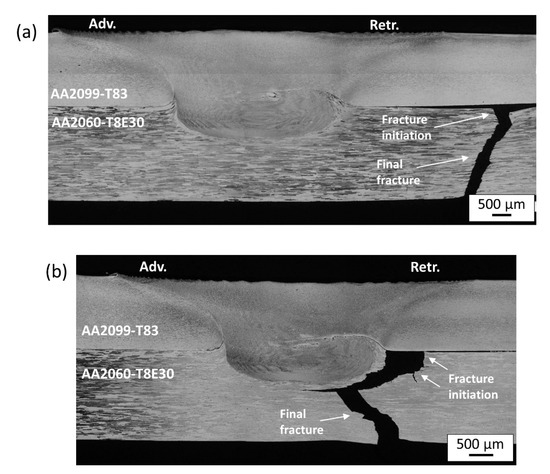
Figure 10.
Metallographic cross-sections of FSW showing different fracture modes; (a) specimen from coupon C05 tested at 30% of the YS showing the fracture out of the FSW joint and (b) specimen from coupon C05 tested at 70% of the YS showing the fracture in the HAZ.
Therefore, from these results, it could be stated that specimens tested in high-stress loading conditions presented a fracture initiation in the HAZ in a similar zone as in the fractures observed in the static tensile tests (Figure 3b). However, the crack growth occurs along the HAZ due to the reduced hardness of the material in this zone. The specimens tested under low-stress conditions showed a fracture out of the FSW joint due to fretting effects produced as a consequence of the frictional contact and sliding movement between the stringer and the skin at their interface. The precise location of the fracture initiation point was randomly distributed along the stringer-skin interface out of the FSW joint, depending on the damage accumulation caused by the frictional contact and the sliding movement between the stringer and the skin.
The presence of surface lubricants has been proposed as a palliative method to reduce fretting fatigue problems and extend the fatigue life of structures [27]. In the FSW joints analysed in this work, the lubricant effect produced by the surface treatments and the applied sealant explains the observed improvement in the fatigue life of these FSW joints. Their presence could reduce the frictional effects at the interface, minimizing the fretting effects and delaying the fracture initiation as well as the final fracture of the FSW specimens.
3.3. Fracture Surface Analysis
The fracture surfaces were investigated in more detail using SEM and EDS techniques. The results obtained in the analysis of the specimen C05_A, which was tested in low-stress loading conditions, are shown in Figure 11, Figure 12 and Figure 13. A general view of the fractured specimen can be observed in Figure 11a and a more detailed view of the fracture surface in Figure 11b. Small regions of black phases were observed at the stringer-skin matching interface, which are indicated as point A1 in Figure 11a, suggesting these phases could act as fatigue crack nucleation points. A detailed analysis of these black phases indicated as regions A1-1 and A1-2 in Figure 12 revealed that they consisted of accumulated aluminium oxides as a result of local sliding and frictional contact between the stringer and skin surfaces at the point A1. Once the fatigue crack was initiated at this point, three main regions were observed for its propagation, indicated as zones A, B and C in Figure 11b. A detailed observation of the fracture surface by SEM allowed us to identify these zones and representative SEM images are shown in Figure 13.
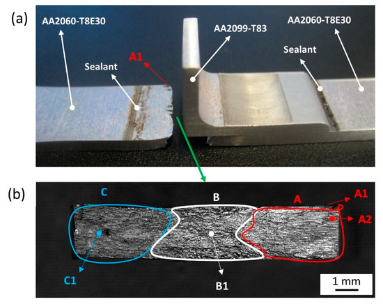
Figure 11.
Fracture surface analysis of specimen C05_A showing the fracture out of the FSW joint at 216,817 cycles (a) general view of the fractured specimen and (b) perpendicular view of the fracture surface indicated by the green arrow.
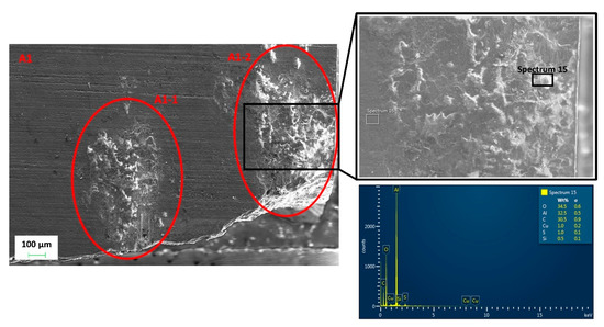
Figure 12.
SEM image and EDS analysis of the zone A1 indicated in Figure 11.
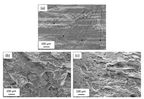
Figure 13a shows a SEM image obtained at point A2 indicated in Figure 11b, which is considered to be close to the initial fatigue crack nucleation point. A very flat surface without significant plastic deformation and the progress of the crack during the cyclic loading of the fatigue test can be observed. This propagation goes from the top surface towards the bottom in thickness as well as from the edge of the specimen towards its centre as indicated by the arrows in Figure 13a. A representative SEM image of the transition zone B obtained at point B1 indicated in Figure 11b can be observed in Figure 13b. A combination of zones showing limited plastic deformation and crack growth bands with other zones showing dimples indicative of ductile fracture with significant plastic deformation could be observed in this zone B. Finally, an SEM image obtained at point C1 in Figure 11b can be observed in Figure 13c. A surface formed of multiple dimples indicative of substantial plastic deformation and ductile fracture could be observed, which was representative of zone C, where the final fracture occurred.
This type of fracture, originated by oxides accumulated at the stringer-skin interface, was representative of the fractures caused by fretting effects in low-stress loading conditions and after a relatively high number of cycles. Thus, fretting effects are the main limiting factor of the fatigue life of stringer-skin FSW joints in the overlap configuration in the high-cycle fatigue regime.
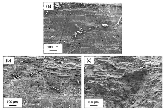
The fractures that occurred in high-stress loading conditions were also investigated by SEM observation of the fracture surfaces. The results obtained in the analysis of the specimen C05_B, that presented a representative fracture in the HAZ of the FSW joint, are shown in Figure 14 and Figure 15. The general view of the fractured specimen can be observed in Figure 14a. No presence of black phases was observed at the stringer-skin interface. A more detailed view of the fracture surface can be observed in Figure 14b showing the main zones which form the final fracture surface: the fatigue crack nucleation and propagation zone (indicated as D) as well as the final fracture zone (indicated as E). Representative images obtained by SEM showing the characteristics of these zones can be observed in Figure 15. Thus, Figure 15a shows details of the initial fatigue crack nucleation point indicated as point D1 in Figure 14b. A flat surface showing no plastic deformation can be observed where propagation bands starting at the top surface indicate the fracture initiation point. The propagation of the fatigue crack, which is indicated by the black arrows in Figure 15a, goes from the top surface towards the bottom in the thickness direction and from the central zone towards the edges in the width of the specimen. Once the crack propagates to cover the zone D, the final fracture occurs in the zone E. SEM images obtained at points E1 and E2 indicated in Figure 14b are shown in Figure 15b and Figure 15c, respectively. Multiple dimples can be observed in these zones indicating a ductile fracture with plastic deformation.
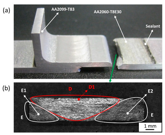
Figure 14.
Fracture surface analysis of specimen C05_B showing the fracture in the HAZ at 52,306 cycles; (a) general view of the fractured specimen and (b) perpendicular view of the fracture surface indicated by the green arrow.
4. Conclusions
The fatigue behaviour of stringer-skin overlapped FSW joints under hoop-stress loading conditions was investigated. AA2099-T83 extrusions and AA2060-T8E30 rolled sheets were used to produce the FSW joints in the as-received and surface-treated conditions. A sealant was also applied at the stringer-skin interface before FSW for some conditions. Based on the results obtained in this work, the following conclusions could be drawn:
- All investigated FSW joints showed an equivalent performance in the static tensile tests carried out under hoop-stress loading conditions. The surface treatments (TFSAA and Sol-Gel) and sealant applied before the manufacturing by FSW did not induce significant effects on the joint properties.
- Two different fracture modes were identified as the main failure mechanisms in the fatigue tests performed under hoop-stress loading conditions. Fractures in the HAZ were observed in tests performed with relatively high stress levels, while the fracture mode in low-stress level tests was found to occur out of the FSW joint.
- IR thermography was found to be a suitable technique for a qualitative analysis of the fatigue performance of FSW joints, allowing us to identify the fracture initiation and propagation locations.
- Fretting fatigue was identified as the main limiting factor of the fatigue life for FSW joints tested at low stress levels. The local damage caused by the frictional contact and sliding movement at the stringer-skin interface was found to create aluminium oxide accumulations that acted as the fatigue crack initiation points.
- FSW joints produced using surface-treated aluminium components and sealant at the stringer-skin interface showed an improved fatigue life in comparison with the FSW joints produced using bare aluminium components. The lubricant effect and reduced friction produced by the surface treatments and sealant at the stringer-skin interface resulted in reduced fretting effects and extended durability of the FSW joints.
Generally, it was concluded that it is feasible to combine FSW manufacturing using surface-treated aluminium alloys and sealants at the stringer-skin interface in order to produce efficient, high-strength and corrosion-resistant aeronautic structures. The possibility of FSW surface-treated aluminium components using sealants was demonstrated and the resulting joints showed improved durability in fatigue tests under hoop-stress loading conditions.
Author Contributions
Conceptualisation, E.A.; formal analysis, E.A.; investigation, E.A., O.Z., J.V. and I.H.; methodology, E.A., O.Z. and J.V.; supervision, P.Á. and I.H.; writing—original draft, E.A. and J.V.; writing—review and editing, E.A., P.Á., I.H. and J.V. All authors have read and agreed to the published version of the manuscript.
Funding
This work was performed in the frame of the project ecoTECH within the AIRFRAME ITD of the Clean Sky 2 programme of the H2020. The authors acknowledge the funding received for this project under the AIRFRAME ITD grant agreement 945521.
Institutional Review Board Statement
Not applicable.
Informed Consent Statement
Not applicable.
Data Availability Statement
Data will be available upon request through the corresponding author.
Acknowledgments
The authors would like to acknowledge Manuel De La Torre from BASF and Chemetall for providing the necessary Naftoseal® MC-780-class C sealant to perform the tests reported in the present work. The authors also thank Maria del Carmen Taboada for her assistance in the fracture surface analysis by SEM and Uxue Irastorza for her support with the metallographic examination tests. Finally, the authors are also thankful to Alexandra Karanika and her team in the Hellenic Aerospace Industry S.A. (HAI) for the application of the surface treatments to the aluminium components.
Conflicts of Interest
The authors declare no conflict of interest.
References
- Starke, E.A.; Staley, J.T. Application of modern aluminum alloys to aircraft. Prog. Aerosp. Sci. 1996, 32, 131–172. [Google Scholar] [CrossRef]
- Aldanondo, E.; Vivas, J.; Álvarez, P.; Hurtado, I. Effect of Tool Geometry and Welding Parameters on Friction Stir Welded Lap Joint Formation with AA2099-T83 and AA2060-T8E30 Aluminium Alloys. Metals 2020, 10, 872. [Google Scholar] [CrossRef]
- Torkamani, H.; Vivas Méndez, J.; Lecart, C.; Aldanondo Begiristain, E.; Alvarez Moro, P.; Antti, M.-L. Effect of Rotation Speed and Steel Microstructure on Joint Formation in Friction Stir Spot Welding of Al Alloy to DP Steel. J. Manuf. Mater. Process. 2022, 6, 24. [Google Scholar] [CrossRef]
- Ambrosio, D.; Aldanondo, E.; Wagner, V.; Dessein, G.; Garnier, C.; Vivas, J.; Cahuc, O. A Semi-Empirical Model for Peak Temperature Estimation in Friction Stir Welding of Aluminium Alloys. Sci. Technol. Weld. Join. 2022, 27, 491–500. [Google Scholar] [CrossRef]
- Jacquin, D.; Guillemot, G. A Review of Microstructural Changes Occurring during FSW in Aluminium Alloys and Their Modelling. J. Mater. Process. Technol. 2021, 288, 116706. [Google Scholar] [CrossRef]
- Murphy, A.; Price, M.; Wang, P. The integration of strength and process modeling of friction-stir-welded fuselage panels. In Proceedings of the 46th AIAA/ASME/ASCE/AHS/ASC Structures, Structural Dynamics and Materials Conference, Austin, TX, USA, 18–21 April 2005; American Institute of Aeronautics and Astronautics: Reston, VA, USA, 2005. [Google Scholar]
- Su, J.-Q.; Nelson, T.W.; Sterling, C.J. Microstructure Evolution during FSW/FSP of High Strength Aluminum Alloys. Mater. Sci. Eng. A 2005, 405, 277–286. [Google Scholar] [CrossRef]
- Cavaliere, P.; Nobile, R.; Panella, F.W.; Squillace, A. Mechanical and Microstructural Behaviour of 2024–7075 Aluminium Alloy Sheets Joined by Friction Stir Welding. Int. J. Mach. Tools Manuf. 2006, 46, 588–594. [Google Scholar] [CrossRef]
- Understanding REACH—ECHA. Available online: https://echa.europa.eu/regulations/reach/understanding-reach (accessed on 25 July 2022).
- ACARE: Advisory Council for Aviation Research and Innovation. Available online: https://www.acare4europe.org/ (accessed on 25 July 2022).
- Dursun, T.; Soutis, C. Recent Developments in Advanced Aircraft Aluminium Alloys. Mater. Des. (1980–2015) 2014, 56, 862–871. [Google Scholar] [CrossRef]
- Karanika, A.; Vourdas, N.; Makrikostas, A.; Marini, R.; Plagianakos, T.; Kalogeropoulos, S. Development of New Environmentally Friendly Anticorrosive Surface Treatments for New Al-Li Alloys Protection within the Frame of Clean Sky2. Procedia Struct. Integr. 2018, 10, 66–72. [Google Scholar] [CrossRef]
- Boldsaikhan, E.; Fukada, S.; Fujimoto, M.; Kamimuki, K.; Okada, H. Refill Friction Stir Spot Welding of Surface-Treated Aerospace Aluminum Alloys with Faying-Surface Sealant. J. Manuf. Process. 2019, 42, 113–120. [Google Scholar] [CrossRef]
- Kubit, A.; Wydrzynski, D.; Trzepiecinski, T. Refill Friction Stir Spot Welding of 7075-T6 Aluminium Alloy Single-Lap Joints with Polymer Sealant Interlayer. Compos. Struct. 2018, 201, 389–397. [Google Scholar] [CrossRef]
- Maciel, R.; Bento, T.; Braga, D.F.O.; da Silva, L.F.M.; Moreira, P.M.G.P.; Infante, V. Fatigue Properties of Combined Friction Stir and Adhesively Bonded AA6082-T6 Overlap Joints. Fatigue Fract. Eng. Mater. Struct. 2020, 43, 2169–2180. [Google Scholar] [CrossRef]
- Gibson, B.T.; Wilkes, D.M.; Cook, G.E.; Strauss, A.M. In-Process Detection of Faying Surface Sealant Application Flaws in Friction Stir Welding. J. Aircr. 2013, 50, 567–575. [Google Scholar] [CrossRef]
- Gibson, B.T.; Cox, C.D.; Ballun, M.C.; Cook, G.E.; Strauss, A.M. Automatic Tracking of Blind Sealant Paths in Friction Stir Lap Joining. J. Aircr. 2014, 51, 824–832. [Google Scholar] [CrossRef]
- Aldanondo, E.; Vivas, J.; Álvarez, P.; Hurtado, I.; Karanika, A. Friction Stir Welding of AA2099-T83 and AA2060-T8E30 Aluminium Alloys with New Cr-Free Surface Treatments and Sealant Application. Metals 2021, 11, 644. [Google Scholar] [CrossRef]
- Kashaev, N.; Ventzke, V.; Çam, G. Prospects of Laser Beam Welding and Friction Stir Welding Processes for Aluminum Airframe Structural Applications. J. Manuf. Process. 2018, 36, 571–600. [Google Scholar] [CrossRef]
- Dubourg, L.; Merati, A.; Jahazi, M. Process Optimisation and Mechanical Properties of Friction Stir Lap Welds of 7075-T6 Stringers on 2024-T3 Skin. Mater. Des. 2010, 31, 3324–3330. [Google Scholar] [CrossRef]
- Schmidt, H.J.; Schmidt-Brandecker, B. Fatigue and damage tolerance behaviour of advanced structures in aeronautics. In Fracture of Materials and Structures from Micro to Macro Scale: 18th European Conference on Fracture; Deutscher Verband für Materialforschung und -prüfung: Berlin, Germany, 2010. [Google Scholar]
- Chhith, S.; De Waele, W.; De Baets, P.; Van Hecke, T. On-Line Detection of Fretting Fatigue Crack Initiation by Lock-in Thermography. Tribol. Int. 2017, 108, 150–155. [Google Scholar] [CrossRef][Green Version]
- Ummenhofer, T.; Medgenberg, J. On the Use of Infrared Thermography for the Analysis of Fatigue Damage Processes in Welded Joints. Int. J. Fatigue 2009, 31, 130–137. [Google Scholar] [CrossRef]
- Yang, H.; Cui, Z.; Wang, W.; Xu, B.; Xu, H. Fatigue Behavior of AZ31B Magnesium Alloy Electron Beam Welded Joint Based on Infrared Thermography. Trans. Nonferrous Met. Soc. China 2016, 26, 2595–2602. [Google Scholar] [CrossRef]
- Croccolo, D.; De Agostinis, M.; Fini, S.; Olmi, G.; Robusto, F.; Scapecchi, C. Fretting Fatigue in Mechanical Joints: A Literature Review. Lubricants 2022, 10, 53. [Google Scholar] [CrossRef]
- Szolwinski, M.P.; Farris, T.N. Mechanics of Fretting Fatigue Crack Formation. Wear 1996, 198, 93–107. [Google Scholar] [CrossRef]
- Lindley, T.C. Fretting fatigue. In Encyclopedia of Materials: Science and Technology; Buschow, K.H.J., Cahn, R.W., Flemings, M.C., Ilschner, B., Kramer, E.J., Mahajan, S., Veyssière, P., Eds.; Elsevier: Oxford, UK, 2001; pp. 3347–3351. ISBN 978-0-08-043152-9. [Google Scholar]


Publisher’s Note: MDPI stays neutral with regard to jurisdictional claims in published maps and institutional affiliations. |
© 2022 by the authors. Licensee MDPI, Basel, Switzerland. This article is an open access article distributed under the terms and conditions of the Creative Commons Attribution (CC BY) license (https://creativecommons.org/licenses/by/4.0/).