Article

Determination of the Influence of the Tool Side Stress Superposition and Tool Geometry on the Cut Surface Quality during Precision Shear Cutting

1
Professorship for Forming and Joining, Chemnitz University of Technology, Reichenhainer Straße 70, 09126 Chemnitz, Germany
2
Fraunhofer Institute for Machine Tools and Forming Technology IWU, Reichenhainer Straße 88, 09126 Chemnitz, Germany
3
Faculty of Mechanical Engineering, VSB—Technical University of Ostrava, 17. Listopadu 2172/15, 708 00 Ostrava, Czech Republic
4
Faculty of Electrical Engineering and Computer Science, VSB–Technical University of Ostrava, 17. Listopadu 2172/15, 708 00 Ostrava, Czech Republic
*
Author to whom correspondence should be addressed.
J. Manuf. Mater. Process. 2023, 7(4), 145; https://doi.org/10.3390/jmmp7040145
Submission received: 29 June 2023 / Revised: 31 July 2023 / Accepted: 1 August 2023 / Published: 8 August 2023

Abstract

:
Shearing high-strength steels often leads to a subpar cut quality and excessive stress on the tool components. To enhance the quality of the cut surface, intricate techniques like fine blanking are commonly employed. However, for applications with lower quality requirements, precision shear cutting offers an alternative solution. This research paper introduces a novel approach to directly superimpose radial stress on a workpiece during the precision shear cutting process and showcases for the first time how the application of direct stress superimposition can impact the cut surface by concurrently modifying the shear cutting edge and punch surface. A statistical experimental design is employed to investigate the interrelationships between the parameters and their effects. The results indicate that the overall cut quality, including cylindricity, clean-cut angle, rollover height, and tool stress, defined by punch force and retraction force, is influenced by the superimposed stress. Regarding the clean-cut zone, the statistical significance of direct radially superimposed stress was not observed, except when interacting with sheet thickness and clearance. Additionally, the sheet thickness and cutting gap emerged as significant parameters affecting the overall quality of the cut surface.

1. Introduction

The automotive sector’s growing emphasis on reduced emissions has made lightweight construction a critical factor, leading to the increased usage of Advanced High Strength Steel (AHSS) with a minimum tensile strength of 440 MPa [1]. By employing fully engineered steel body structures, weight reductions of up to 180 kg are achievable, resulting in a nearly 70% decrease in the overall life cycle of greenhouse gas emissions [2]. The shear cutting process, known for its speed, cost-effectiveness, and chipless nature, is widely employed in industrial applications. As the shearing operation is frequently integrated into various forming processes, the quality of the post-forming stage relies heavily on the quality of the sheared edge. However, regression analyses of cut surface data have revealed that as the tensile strength of the workpiece increases, the clean-cut zone and rollover diminish while the rough fracture zone expands [3]. The hole expansion test, which evaluates the stretch flangeability of the sheared edge, exhibits lower limiting expansion ratios for specimens with higher tensile strengths. In these cases, the impact of macroscopic irregularities outweighs the significance of fracture zone roughness [4]. Moreover, reducing roughness is desirable for enhancing the fatigue limit of high-strength steel [5]. Consequently, there is a urgent need to adapt conventional shear cutting processes to achieve high-quality shearing of high-strength steel, with precision shear cutting incorporating direct radial pre-stress superposition and a modified tool setup being one promising method [6]. This study focuses on measuring the characteristics of the cut surface, as well as the form and positional tolerances of holes, sheared using different system parameters such as clearance, cutting edge and face geometry at the punch, sheet thickness, and radial pre-stress. The obtained results are subsequently subjected to a statistical analysis to identify the most influential factors and determine the optimal parameter combination for achieving a high-quality cut surface.

1.1. Single-Stroke Shear Cutting and Its Characteristics

Single stroke shear cutting is a cutting method where the entire cut line is completed in a single stroke. The tool setup and parameters vary depending on the desired cut surface quality and the complexity of the tooling. In the conventional shear cutting process, the workpiece is sheared between a die and punch with a larger clearance (ranging from 5% to 15% of the initial sheet thickness, denoted as s 0 ), while the sheet is held by the blank holder [7]. On the other hand, the fine blanking process utilizes a counter punch and a blank holder equipped with a vee-ring. This process allows for a much smaller clearance (0.5% of s 0 ) and enables the achievement of a clean-cut zone that spans 100% of s 0 [8]. Precision shear cutting, in terms of cut quality, falls between the conventional shear cutting and fine blanking methods. It offers achievable tolerances ranging from IT 7 to IT 11 with relatively simple equipment [6]. This system is characterized by a flat blank holder and counter punch, a rounded punch or die edge, and a smaller clearance (1.3% of s 0 ) [7].

1.2. Cut Surface Characteristics and Influencing Factors

According to the VDI 2906-2 [9], the cut surface of a sheared sheet metal part consists of the rollover, clean-cut zone, fracture zone, and burr, as shown in Figure 1. These characteristics are associated with the different phases undergone during the shear cutting process.
In general, a good cut surface quality is characterized by a smaller value of rollover height and width, smaller fracture zone, smaller burr height and width, and a larger clean-cut zone with a 90° clean-cut angle [7]. The important process parameters influencing the cut surface quality are clearance, the geometry of the active tool parts, workpiece material, cutting speed, etc. [9]. The influence of clearance, which is the cutting gap between two blades or between punch and die, has been studied many times in the literature. The increasing clearance generally decreases the cut quality by increasing the rollover, fracture zone, fracture angle, and burr, and decreasing the clean-cut zone [3,9]. These observations are linear for up to 20–30% of the clearance [10]. Further investigation of the influence of the cutting gap was done with the help of the Cockroft & Latham failure criterion in [11]. In detail, an increase in the cutting gap means an increase in the shear band, which in turn leads to premature separation in the material. However, the experiment done by Han [12] did not show any change in the clean-cut zone for high strength steel greater than 500 MPa with a sheet thickness of 1.42 mm. As already defined by precision shear cutting, the rounding of the cutting edge has a positive effect on the quality of the sheared edge. The FEM is a suitable tool for investigating the influence of cutting edge geometry. For example, the load on a tool coating during the shearing process can be determined. The investigation shows that the combination of a chamfer and a rounding on the cutting edge can reduce the load considerably [13]. Further investigation into the modelling of the cutting punch for shear cutting of high strength materials with an open cutting line can be found in [14]. The failure is described by a phenological model with a modified Mohr–Coulomb approach. In the simulation results, a 7° chamfer on the face is shown to be useful to reduce the stress in the cutting punch, even if the maximum cutting force increases compared to the flat face. The increase of the punch radius increases the clean-cut zone [15]. However, the increased rounding radius may additionally increase the rollover and burr formation. Therefore, a small rounding radius is optimum for ultra-high strength steel (UHSS) in terms of both the tool life and the clean-cut zone [16]. Different punch faces are beneficial for reducing the load while shearing high strength steel. For example, by using two-way convex sheared rooftop punches, the punching force is significantly reduced with an increase in shear angle as compared to the flat punch. But at the same time, rollover and burr height also become larger [17]. The finite element analysis has shown minimum burr heights for chamfered and convex punches compared to flat punches [18]. Another parameter influencing the quality of the cut surface during fine blanking is the blank holder force and the counter holder force. In [19], this influence is discussed with the help of the FEM; it is shown that a higher cutting surface quality can be achieved with increased blank holder and counter holder forces. The adiabatic separation based on a high-speed impact cutting machine with a velocity up to 10 m/s is defined by the Fraunhofer Institute of Machine Tools and Forming Technology, with the possibility to achieve almost burr-free cut surfaces [20]. The experiments done with various cutting speeds have shown a decreased rollover, smoother surface, and negligible burr with high-speed settings [21]. The investigations in [22] also came to similar results, whereby the minimum necessary shear cutting energy could be determined by using linear motors in a test bench.

1.3. Superposition of Compression Stress

The behavior of a material during loading is determined by its stress state. The stress tensor can be divided into hydrostatic and deviatoric components, with the hydrostatic part being negligible in a constant-volume forming process. However, as discussed in Doege [23], superimposing a stress state to increase the compression component of the hydrostatic part enhances deformability. In the shear cutting phase, the proportion of the clean-cut zone increases when the initiation of the crack leading to the fracture zone can be delayed. This delay can be achieved by increasing the compressive stress state, which is observed in fine and precision shear cutting. The reduction in hydrostatic stress has been addressed by Hörmann [24] in relation to lower clearance, rounded cutting edges, and shearing with a vee-ring. Similarly, a numerical study demonstrated that a higher compressive stress state can be attained by employing a concave nose punch instead of a conventional punch shape. The optimized geometrical value of the punch resulted in a clean-cut zone proportion of 73% even in a conventional tool setup [25]. Subsequently, an experimental study confirmed the increased clean-cut zone proportion using the concave nose punch [26]. The same authors conducted another numerical study to investigate the replacement of the conventional blank holder with a Z-shaped blank holder, aiming to superimpose a compression state on the blank prior to shear cutting. In this case, the achievable clean-cut zone proportion was 67% even with a conventional tool setup [27]. In this study, unlike current technologies, the application of direct radial forces on the four edges of the workpiece using four hydraulic block cylinders is employed to superimpose compressive stress. This approach enables the manipulation of the stress state for an improved shear cutting performance.

2. Materials and Methods

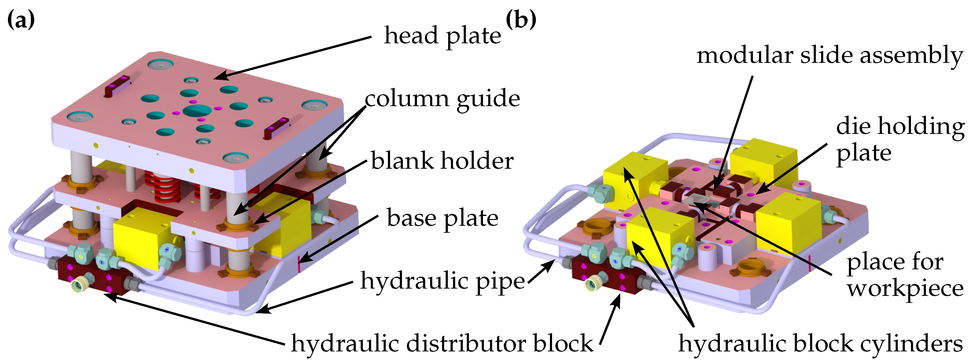
The developed tool concept for stress superimposition in precision shear cutting is shown in Figure 2a. The upper tool is guided to the lower tool via four columns. In the upper tool, there are helical compression springs for applying the holding-down forces in the range of 16 to 80 kN. In the lower tool (Figure 2b), the cutting die can be changed in the die holding plate to vary the cutting gaps between 1.3 to 10% of the sheet thickness. The application of the stress superposition in the process is carried out by the four hydraulic block cylinders, which press evenly on the four workpiece edges. They allow a maximum pre-tension of 100 kN per cylinder. The sensors integrated into the servo screw press enabled the measurement of punch displacement, blank holder force, and displacement, as well as counter holder force and displacement with a maximum system-dependent measuring frequency of 1000 Hz. The punch and four slide forces were measured via the force rings built into the tool and a charge amplifier was used to record these forces at a measuring frequency of 10,000 Hz.
To reduce the number of experiments determined according to the morphological box, the statistical design tool integrated with Origin 2020 software was used. The high-strength hot-rolled micro-alloyed steel S500MC was used for all tests, and the mechanical properties were determined in advance (Table 1). The extremes in Table 2 were preselected as input parameters for the experimental design. Specifically, the sheet thickness s 0 varied between 3 and 8 mm, and the punch face varied between a flat shape and a convex shape with a radius of 100 mm. Additionally, either a sharp cutting edge or a cutting edge with a radius of 0.2 mm was used. The variation of the cutting punch geometry is also outlined in the three shapes in Figure 3.
The cutting gap was varied as a percentage of the sheet thickness from 1.3 to 10%. The selection of the stress superposition was based on the results of Neugebauer et al. [6], and it was defined by the percentage of the yield strength R e . Using the 2 5 1 design approach with five input factors resulted in 16 trials and the factor combination for each trial is shown in Table 3. Each test combination was performed with five repetitions but each measurement task was done for a single sample. The shear cutting oil used had a viscosity of 180 mm2/s, and the counter-holding force was calculated as 15% of the maximum cutting force, which was 18.5 kN for the tests with a sheet thickness of 3 mm and 54.5 kN for 8 mm. The cutting speed was constant at 1 mm/s for all tests.
The determination of the quality of the cut surface was carried out on the perforated workpiece in accordance with the VDI guideline 2906-2 [8] and was measured using the Keyence VHX-600 digital microscope. Since a significant advantage of stress-superimposed precision shear cutting is primarily the improvement of the clean-cut zone or the functional surface even with the cutting gaps usually present in conventional shear cutting, this criterion was the main focus when determining the cut surface parameters. The workpieces were marked accordingly before shear cutting so that the subsequent measuring points of the primary smooth cut were directly comparable with each other (Figure 4a). Additional quality criteria for the production of internal contours are the deviation from the cylinder and the perpendicularity of the axis to the surface. For measuring the deviation of the cut surface from its ideal geometry, cylindricity was used as a shape measurement, and perpendicularity was used as an orientation measurement. The 3D scanner used was the GOM Atos Core 200, based on fringe projection with a narrowband blue light to filter out any ambient light. The scanned data was polygonized and the created mesh was exported into GOM Inspection 2019, where a fitting cylinder with the Chebyshev best fit was created in the middle location. The cylindricity deviation is calculated as defined in DIN EN ISO 12180-1,2 [28,29]. Similarly, the Chebyshev best fit was also used to create a reference plane on the lower surface of the scanned part and perpendicularity deviation as defined in the ISO 1101 standard [30] with a ’circular tolerance zone’ type being used. An exemplary evaluation of cylindricity and perpendicularity in the GOM Inspect software (version: 2022-156191; creator: Carl Zeiss GOM Metrology GmbH; Braunschweig, Germany) after the measurement is shown in Figure 4b.

3. Results and Discussion

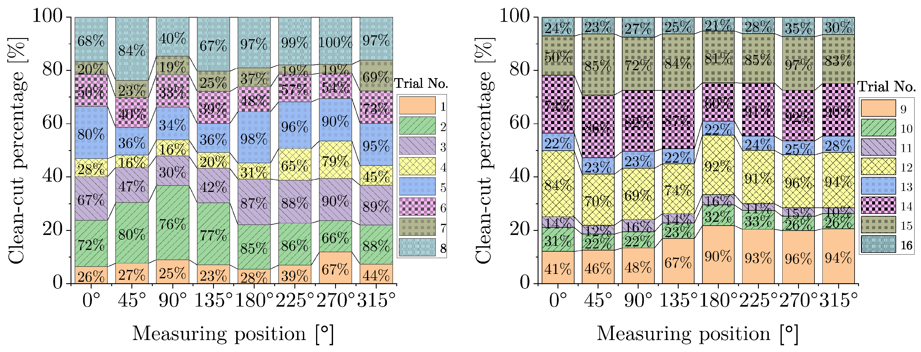
The preliminary assessment of the clean-cut zone at different angular positions for the resulting 16 trials with different input parameter combinations is depicted in Figure 5a,b. It appears that the clean-cut zone has higher values at positions ranging from 180° to 315° compared to positions from 0° to 135°. One possible explanation for this trend could be a mismatch between the center of the punch and the die. A brief analysis of the standard deviation shows that the deviation is greater for the configuration with 1.5% clearance and 3 mm sheet thickness, which are both associated with a smaller absolute value of clearance gap. Further analysis from this point onward was done at the measuring position with a minimum value of clean-cut percentage.

3.1. Influence on Cylindricity and Perpendicularity Error

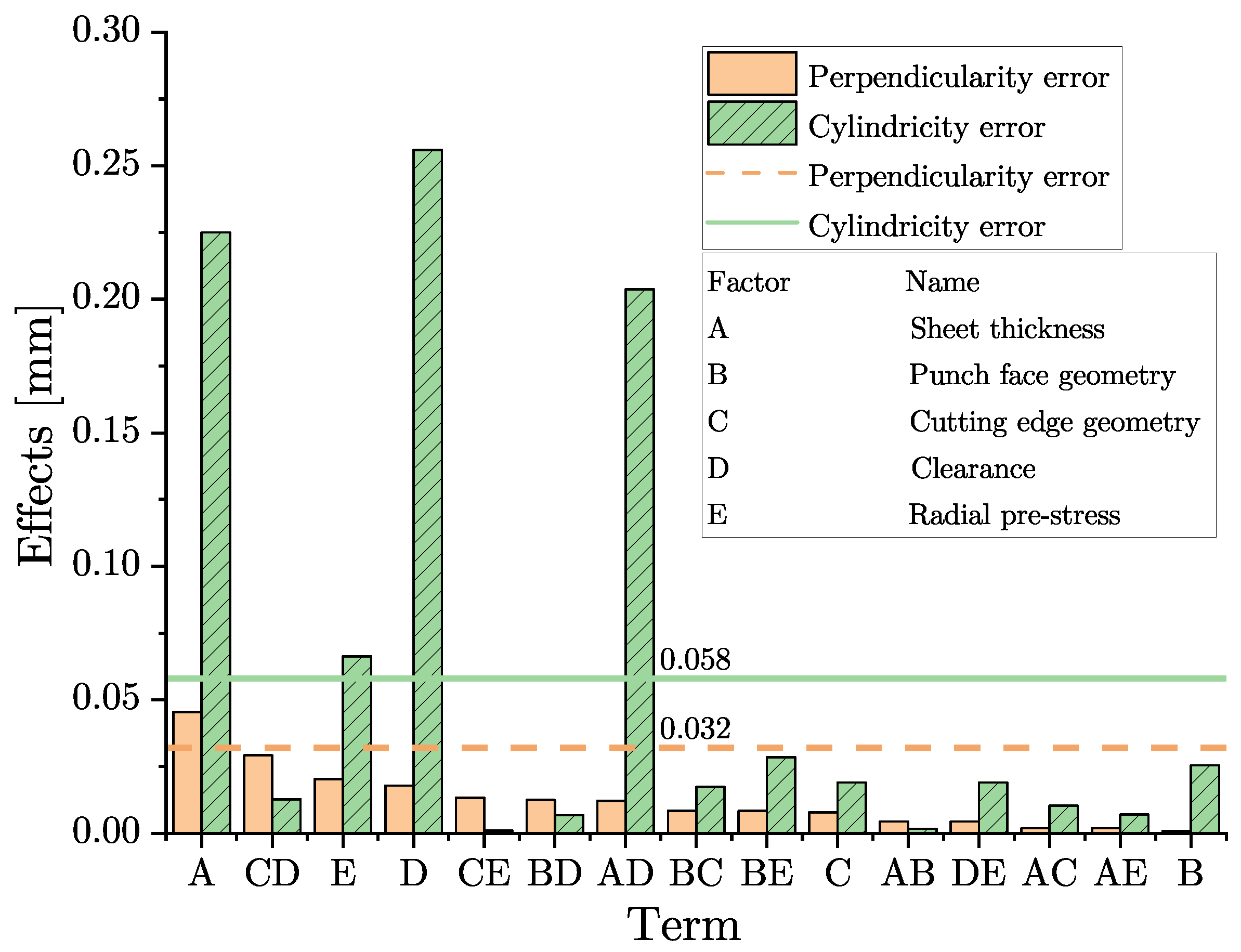
The effect plot displays the difference in mean values of a factor or interaction at two given levels. In experiments with no replication, Origin employs Lenth’s method to draw the reference line for statistical significance. Figure 6 shows such a plot for a significance level of 5%. For perpendicularity, only sheet thickness showed a significant effect, whereas for cylindricity, clearance, radial pre-stress, and the interaction between sheet thickness and clearance (AD) were all found to be significant.
As shown in the bar plots in Figure 7a,b, the errors increase with an increase in sheet thickness (A), which is likely due to the higher possibility of deviation when measuring a larger surface area compared to a smaller surface. The presence of a smaller clearance (D) of 1.3% and pre-stress (E) leads to a relatively higher value of the clean-cut zone, which is observed to reduce the cylindricity error. The absolute value of clearance is dependent on the sheet thickness, causing the interaction AD to be significant for cylindrical deviation. Although the literature [16,24] supports good cut quality for rounded cutting edges, the significant influence of the geometrical characteristics of the tool, such as the punch face (B) and cutting edge (C), could not be conclusively determined in this experiment. This result could be traced back to the clean-cut zone, which in this experiment is also not significantly influenced by the punch face and cutting edge geometry. The probable reason for it can be that stress reduction, due to the reduced notch effect of the rounded edge, is only significant when the clearance is much lower than 1.3%.

3.2. Influence on the Clean-Cut Zone

The main effects of the thickness (A) and clearance (D) were also found to be significant for the clean-cut zone. As shown in Figure 8a, there was no significant direct influence of punch face geometry (B), punch cutting edge geometry (C), and radial pre-stress (E), but significant interaction effects were observed for AD, BC, DE, and AE. It is evident that a higher thickness results in a higher absolute amount of the clean-cut zone, but when expressed in terms of sheet thickness percentage, the values were nearly the same. The higher value of the clean-cut amount at 1.3% clearance than at 10% (Figure 8b) is due to an increased compressive stress state in the shear zone, leading to a delayed fracture [24].

3.3. Influence on the Clean-Cut Angle and Fracture Surface Angle

For a lower perpendicularity deviation, it is favorable if the angles associated with the clean-cut zone and fracture zone are as close as possible to 90°. For all the 16 trials conducted, the clean-cut angles are in the range between 87° to 89.5°. Out of the five input parameters, only sheet thickness (A) and radial pre-stress (E) were found to significantly influence the clean-cut angle, although it was expected to find the significance of clearance as well (Figure 9a). As seen in Figure 9b, when using an 8 mm thick blank and with radial pre-stress, the angle gets closer to 90° by 2° in comparison to a blank with 3 mm of thickness and with no radial pre-stress. A longer stroke length with higher thickness means higher time for the blank material to be sheared along the punch side walls and this may have helped the clean-cut zone to retain perpendicularity. As will be seen in the next section, the additional pre-stress helps in reducing the rollover height significantly and this could be the reason why the clean-cut angle is closer to 90° for the case of superposed stress.
In contrast, fracture surface angles have higher dispersion for the 16 trials with the range between 72° to 85°. Here, the radial pre-stress had no significant effect, but only the cutting edge radius (C) and clearance (D) (Figure 10a). The plot for the individual parameter can be seen in Figure 10b. As expected, a higher gap between the punch and die causes the fracture to travel along a lower-angled path and thus resulting in a lower fracture angle. This can be visualised using basic trigonometry. In the case of a rounded cutting edge, the better angle could be related to the fact that when using a rounded punch and a sharp die, the crack formation in the blank takes place only from the die edge side as shown in [16].

3.4. Influence on Rollover Height and Width

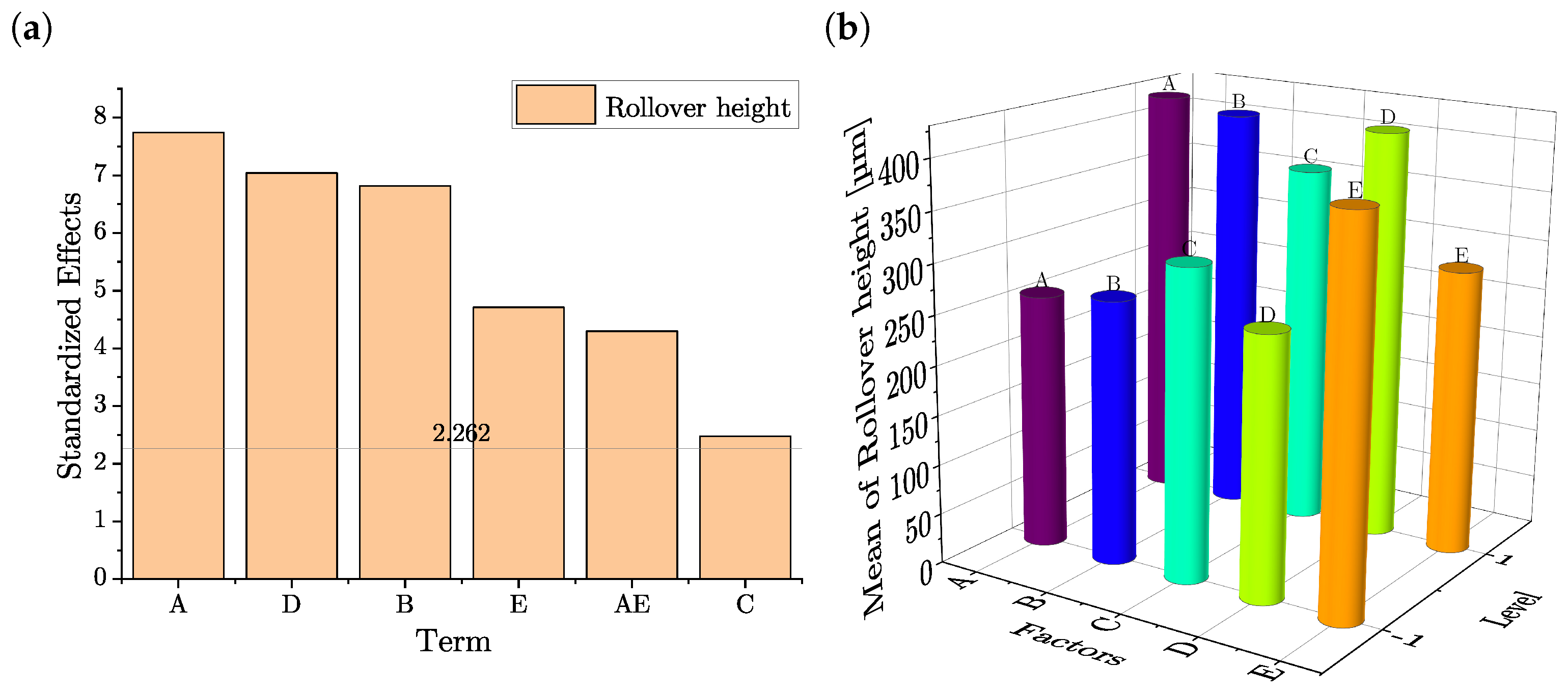
In contrast to the clean-cut zone, a lower value of rollover height and width is desirable for a good cut quality. All main factors were found to be significantly active in influencing the rollover height. Additionally, Figure 11a shows that the interaction between sheet thickness (A) and radial pre-stress (E) is also important. Thicker sheets and increased clearance (D) largely increase the rollover height (Figure 11b). The larger cutting gap increases the bending moment and allows more material to flow into it. At the beginning of the shearing process, when a punch with a convex face (B) is used, the effective cutting gap increases as the point of contact between the punch and blank is shifted towards the center, leading to an increased moment and thus, rollover height.
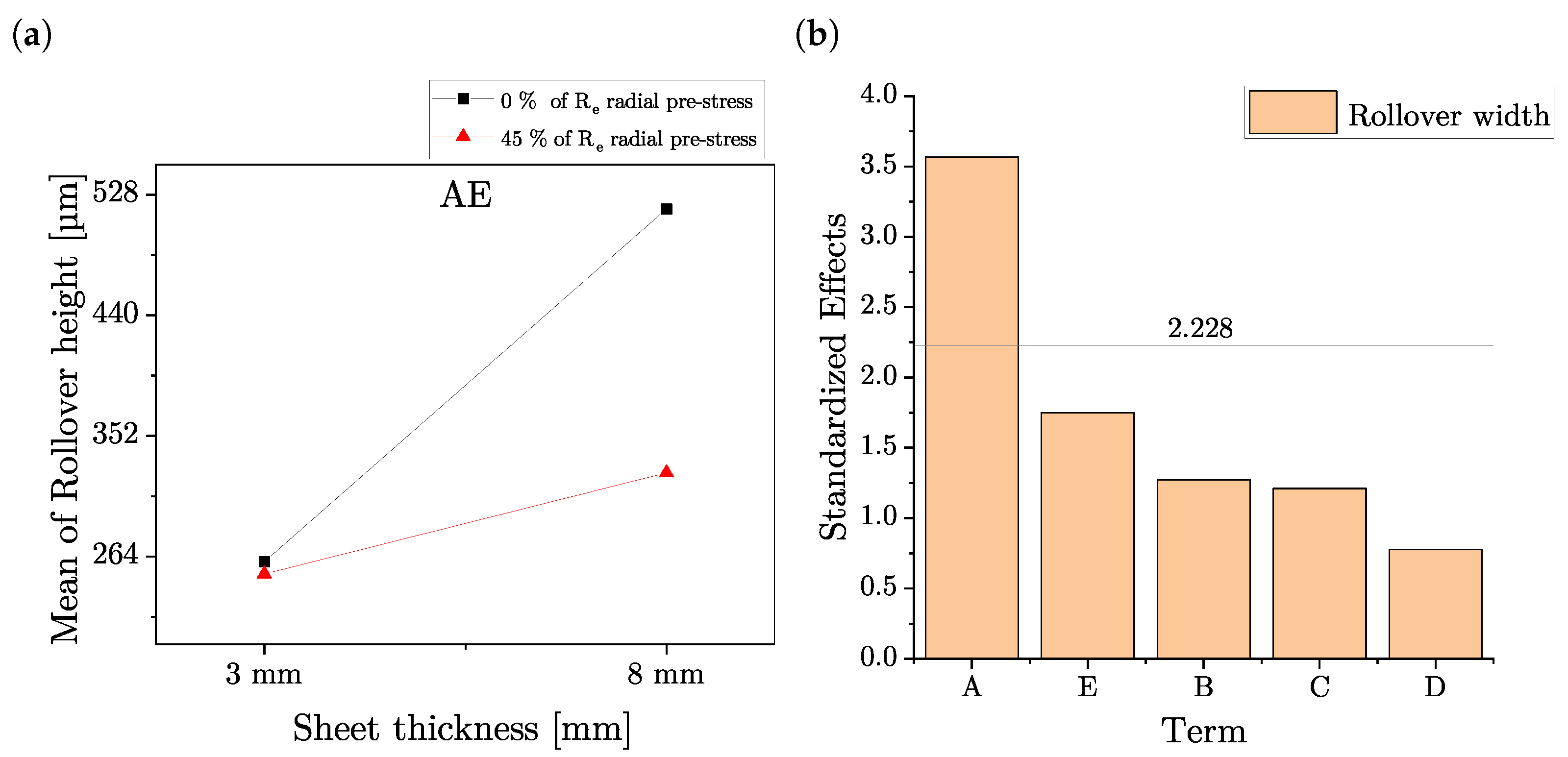
The additional radial pre-stress has a positive effect on reducing the stretching of the outer sheet material, thereby reducing the rollover height. Furthermore, the influence of additional stress is more advantageous in reducing the rollover height for a thicker sheet, as shown by the AE interaction plot in Figure 12a. VDI 2906-5 provides a relation where the rollover width is given approximately five times the rollover height for common tool conditions. Based on this relation, it was expected that different factors would have a similar influence on rollover width. However, Figure 12b shows that only sheet thickness (A) is a statistically significant term. This may be due to higher influence in material flow further beyond the cutting edge as a result of the increased punch stroke length with an increase in thickness.

3.5. Influence on Shear Cutting and Retraction Force

Parallel to the evaluation of the shear cutting surface quality, the forces for the various tests were also evaluated. In particular, the maximum shear cutting force and the minimum shear cutting force (retraction force) were considered. With the help of the DOE, it was also possible to make the parameter influences visible here. The results are summarized in Figure 13 using the example of a sheet thickness of 8 mm. In the consideration of the maximum shear cutting force, it became apparent that the cutting edge geometry does not reach the significance level of p = 0.05 . However, the other factors are significant and changing the punch face from flat to convex results in a slight increase in force, due to the increasing amount of bending before the material separates. Meanwhile, an increase in the cutting gap results in a decrease in the shear cutting force and, as expected, radial stress superposition provides an increase in the force (Figure 13a) due to the increase in friction between the workpiece and the tool. In the evaluation of the retraction force, all factors are significant, and changing the punch face from flat to convex and changing the cutting edge from sharp to rounded leads to an increase in the retraction force. However, a larger cutting gap and radial stress superposition reduce the retraction force (Figure 13b). This is due to the reduced friction caused by the larger gap between the workpiece and the tool and, in the case of stress superposition, due to the release of elastic stresses after unloading the workpiece.

4. Conclusions and Outlook

To improve the quality of the cut surface and increase the tool life of shear cutting for high-strength steels, further development of the previous shear cutting processes is necessary. Therefore, precision shear cutting with radial stress superposition was presented. To determine the effects on workpiece quality, a statistical experimental design was conducted. The results showed that the main factors influencing the cut surface quality are sheet thickness and the cutting gap. However, when combined with pre-load and sheet thickness or the cutting gap, it is possible to influence the cut surface quality. It was determined that the maximum clean-cut percentage is achieved with a sheet thickness of 3 mm, a cutting gap of 1.3% of s 0 , and a pre-load of 45% of R e . The following points summarize the results obtained in this study:
  • The radial pre-stress decreases the cylindricity error and rollover height, and increases the perpendicularity of the clean-cut zone.
  • In terms of the clean-cut zone, pre-stress has a significant interaction with the sheet thickness and clearance. In terms of rollover height, it has a significant interaction only with the sheet thickness and is of much importance when considering thicker sheets.
  • The radial pre-stress increases the punch force but on the other hand, it helps in reducing tool wear causing retraction force.
  • The perpendicularity error is solely dependent on the sheet thickness. This may be due to the absolute value of the fracture zone and its angle.
  • Rollover height depends on every main factor and rollover width is dependent only on sheet thickness.
  • In addition to rollover height, the cutting edge geometry is also important for the fracture surface angle, where a rounded edge was better than a sharp edge by around 6°.
Further, it should also be noted that because of the linear design of the experiment, the conclusions may not be valid outside the level limit and the effects may not be linear as shown here. In the future, there are plans to further investigate the load on the active elements of the tool during stress superposition. The changes to the punch face and cutting edge geometries are expected to reduce the stress peaks in the cutting punch. The optimization of the punch geometry will be carried out by means of an FE model that will be validated by the tests. Further investigations into the influence of the shear cutting speed and also the effect on wear are planned.

Author Contributions

Conceptualization, D.W., A.G. and V.K.; formal analysis, A.G. and P.B.; investigation, A.G. and P.B.; writing–original draft preparation, A.G. and P.B.; writing–review and editing, D.W., J.P., J.K. and V.K.; project administration, A.G. and V.K. All authors have read and agreed to the published version of the manuscript.

Funding

This research was funded by the German Research Foundation (DFG) as part of the project “Influence of the tool on the stress state in precision cutting” (project number:415999781). This paper was completed in association with the project Innovative and additive manufacturing technology—new technological solutions for 3D printing of metals and composite materials, reg. no. CZ.02.1.01/0.0/0.0/17_ 049/0008407 financed by the Structural Funds of the European Union and project. This work has received funding from the European Union’s Horizon 2020 research and innovation programme under grant agreement No. 856670. The publication of this article was funded by Chemnitz University of Technology and by the Deutsche Forschungsgemeinschaft (DFG, German Research Foundation)—491193532.

Data Availability Statement

The data can be requested anytime from the corresponding author.

Conflicts of Interest

The authors declare no conflict of interest.

Abbreviations

The following abbreviations are used in this manuscript:
AHSSAdvanced High Strength Steel
ITISO degree of Tolerance
UHSSUltra High Strength Steel
VDIAssociation of German Engineers

References

  1. Samodajev, N. Advanced High Strength Steel (AHSS) for Stronger, Lighter and Safer Cars. Available online: https://matmatch.com/blog/advanced-high-strength-steel-stronger-lighter-safer-cars/ (accessed on 22 September 2021).
  2. World Steel Association. Steel in Automotive. Available online: https://worldsteel.org/steel-topics/steel-markets/automotive/ (accessed on 22 September 2021).
  3. Levy, B.S.; van Tyne, C.J. Review of the Shearing Process for Sheet Steels and Its Effect on Sheared-Edge Stretching. J. Mater. Eng. Perform. 2012, 21, 1205–1213. [Google Scholar] [CrossRef]
  4. Mori, K.i.; Abe, Y.; Suzui, Y. Improvement of stretch flangeability of ultra high strength steel sheet by smoothing of sheared edge. J. Mater. Process. Technol. 2010, 210, 653–659. [Google Scholar] [CrossRef]
  5. Matsuno, T.; Kuriyama, Y.; Murakami, H.; Yonezawa, S.; Kanamaru, H. Effects of Punch Shape and Clearance on Hole Expansion Ratio and Fatigue Properties in Punching of High Strength Steel Sheets. Steel Res. Int. 2010, 81, 853–856. [Google Scholar]
  6. Neugebauer, R.; Kräusel, V.; Barthel, T.; Jesche, F.; Schönherr, J. Influence of a defined pre-load on the stress state in the precision cutting process. CIRP Ann. 2013, 62, 271–274. [Google Scholar] [CrossRef]
  7. Hoffmann, H. Handbuch Umformen; Edition Handbuch der Fertigungstechnik, Hanser Verlag: München, Germany, 2012. [Google Scholar]
  8. VDI 2906. Quality of Cut Faces of (Sheet) Metal Parts After Cutting, Blanking, Trimming or Piercing; Sheet 5: Fineblanking; VDI Verein Deutscher Ingenieure: Düsseldorf, Germany, 1994. [Google Scholar]
  9. VDI 2906. Quality of Cut Faces of (Sheet) Metal Parts After Cutting, Blanking, Trimming or Piercing Shearing, Form of Sheared Edge and Characteristic Values; Sheet 2: Shear Cutting; VDI Verein Deutscher Ingenieure: Düsseldorf, Germany, 1994. [Google Scholar]
  10. Chintamani, J.; Sriram, S. Sheared Edge Characterization of Steel Products used for Closure Panel Applications. In Proceedings of the SAE 2006 World Congress and Exhibition, SAE International, Detroit, MI, USA, 3–6 April 2006. [Google Scholar] [CrossRef]
  11. Kwak, T.S.; Kim, Y.J.; Bae, W.B. Finite element analysis on the effect of die clearance on shear planes in fine blanking. J. Mater. Process. Technol. 2002, 130–131, 462–468. [Google Scholar] [CrossRef]
  12. Han, S.S. Study for Sheared Edge Quality of High Strength Steel Sheet. Key Eng. Mater. 2014, 626, 252–257. [Google Scholar] [CrossRef]
  13. Klocke, F.; Sweeney, K.; Raedt, H. Improved tool design for fine blanking through the application of numerical modeling techniques. J. Mater. Process. Technol. 2001, 115, 70–75. [Google Scholar] [CrossRef]
  14. Nothhaft, K.; Suh, J.; Golle, M.; Picas, I.; Casellas, D.; Volk, W. Shear cutting of press hardened steel: Influence of punch chamfer on process forces, tool stresses and sheared edge qualities. Prod. Eng. 2012, 6, 413–420. [Google Scholar] [CrossRef]
  15. Ishiguro, T.; Yoshida, Y.; Yukawa, N.; Ishikawa, T. Deformation Analysis of Shearing Process Using Results of Notched Round Bar Tension Test. Mater. Trans. 2009, 50, 1671–1677. [Google Scholar] [CrossRef] [Green Version]
  16. Mori, K.; Abe, Y.; Kidoma, Y.; Kadarno, P. Slight clearance punching of ultra-high strength steel sheets using punch having small round edge. Int. J. Mach. Tools Manuf. 2013, 65, 41–46. [Google Scholar] [CrossRef]
  17. Kutuniva, K.; Karjalainen, J.A.; Mäntyjärvi, K. Effect of Convex Sheared Punch Geometry on Cutting Force of Ultra-High-Strength Steel. Key Eng. Mater. 2012, 504–506, 1359–1364. [Google Scholar] [CrossRef]
  18. Shaheen, W.; Kanapathipillai, S.; Mathew, P.; Prusty, B.G. Optimization of compound die piercing punches and double cutting process parameters using finite element analysis. PRoceedings Inst. Mech. Eng. Part J. Eng. Manuf. 2020, 234, 3–13. [Google Scholar] [CrossRef]
  19. Thipprakmas, S.; Jin, M.; Murakawa, M. An investigation of material flow analysis in fineblanking process. J. Mater. Process. Technol. 2007, 192–193, 237–242. [Google Scholar] [CrossRef]
  20. Fraunhofer IWU. High Speed Impact Cutting of Sheets and Tubes. Available online: https://www.iwu.fraunhofer.de/content/dam/iwu/en/documents/Infosheet/Infosheet-High-Speed-Impact-Cutting-Of-Sheets-And-Tubes.pdf (accessed on 24 October 2021).
  21. Gu, J.; Alamos, F.; Schoch, D.; Bornhorst, J.; Kim, H. A Study on Effects of the Press Speed on Sheared Edge Formability. IOP Conf. Ser. Mater. Sci. Eng. 2020, 967, 012064. [Google Scholar] [CrossRef]
  22. Krutz, P.; Leonhardt, A.; Graf, A.; Winter, S.; Rehm, M.; Kräusel, V.; Dix, M. Development and testing of a flexible test bench for high-speed impact shear-cutting with linear motors. In Proceedings of the SHEMET 2023—20th International Conference on Sheet Metal, Erlangen, Germany, 2–5 April 2023; MaterialsResearchForum LLC: Nuremberg, Germany, 2023; pp. 19–26. [Google Scholar] [CrossRef]
  23. Doege, E. Handbuch Umformtechnik: Grundlagen Technologien Maschinen; Springer eBook Collection Computer Science & Engineering, Springer: Berlin/Heidelberg, Germany, 2010. [Google Scholar] [CrossRef]
  24. Hörmann, F. Einfluss der Prozessparameter auf einstufige Scherschneidverfahren zum Ausschneiden mit endkonturnaher Form. Ph.D. Thesis, Technische Universität München, München, Germany, 2008. [Google Scholar]
  25. Senn, S.; Liewald, M. Numerical investigation of a new sheet metal shear cutting tool design to increase the part quality by superposed compression stress. J. Phys. Conf. Ser. 2018, 1063, 012181. [Google Scholar] [CrossRef]
  26. Senn, S.; Liewald, M. Investigation of a new sheet metal shear cutting tool design to increase the part quality by superposed compression stress. IOP Conf. Ser. Mater. Sci. Eng. 2019, 651, 012088. [Google Scholar] [CrossRef]
  27. Briesenick, D.; Liewald, M.; Senn, S. Improvement of shear cutting process by stress superposition via cross-elastic partholder. IOP Conf. Ser. Mater. Sci. Eng. 2022, 1238, 012027. [Google Scholar] [CrossRef]
  28. DIN EN ISO 12180-1; Geometrische Produktspezifikation (GPS)—Zylindrizität—Teil 1: Begriffe und Kenngrößen der Zylinderform. Beuth Verlag GmbH: Berlin, Germany, 2011.
  29. DIN EN ISO 12180-2; Geometrische Produktspezifikation (GPS)—Zylindrizität—Teil 2: Spezifikationsoperatoren. Beuth Verlag GmbH: Berlin, Germany, 2011.
  30. DIN EN ISO 1101; Geometrische Produktspezifikation (GPS)—Geometrische Tolerierung—Tolerierung von Form, Richtung, Ort und Lauf. Beuth Verlag GmbH: Berlin, Germany, 2017.
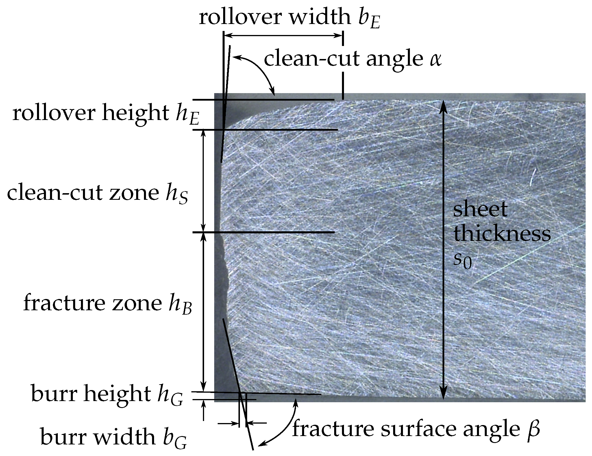
Figure 1. Definition of the cut surface characteristics in reference to VDI 2906-2 [9] on a cross-section of a cut surface [Image source: Authors].
Jmmp 07 00145 g001
Figure 2. (a) Design of the experimental tool for precision shear cutting with stress influence on the tool side and (b) assembly of the lower part of the tool with the clamping device.
Jmmp 07 00145 g002
Figure 3. Drawing of the variation of the geometry of the shear cutting punch: (a) flat punch face and sharp cutting edge; (b) convex punch face; (c) rounded cutting edge.
Jmmp 07 00145 g003
Figure 4. Cut surface characteristics measurement: (a) cuts to divide the sample and (b) optical scanned surface in GOM Inspect.
Jmmp 07 00145 g004
Figure 5. Clean-cut zone percentage at different angular positions.
Jmmp 07 00145 g005
Figure 6. Effect plot for cylindricity and perpendicularity errors.
Jmmp 07 00145 g006
Figure 7. Main effect plot for the (a) cylindricity error and (b) perpendicularity error.
Jmmp 07 00145 g007
Figure 8. Statistical plot for the clean-cut zone (a) effects plot and (b) main effect plot.
Jmmp 07 00145 g008
Figure 9. Statistical plot for the clean-cut angle (a) effects plot and (b) main effect plot.
Jmmp 07 00145 g009
Figure 10. Statistical plot for the fracture surface angle (a) effects plot and (b) main effect plot.
Jmmp 07 00145 g010
Figure 11. Statistical plot for the rollover height (a) effects plot and (b) main effect plot.
Jmmp 07 00145 g011
Figure 12. (a) Interaction between sheet thickness and (b) radial pre-stress and effects plot for rollover width.
Jmmp 07 00145 g012
Figure 13. Determined parameter influences on the (a) shear cutting force and (b) retraction force for the sheet thickness of 8 mm.
Jmmp 07 00145 g013
Table 1. Summary of the mechanical properties of the microalloyed steel S500MC determined in the tensile test.
Sheet
Thickness
s 0 [mm]
Rolling
Direction
[°]
Young’s
Modulus
[GPa]
Yield
Strength
R e [MPa]
Tensile
Strength
R m [MPa]
Elongation
at Break
A 80 [%]
3018852060110.3
451845325789.9
902495746129.1
8018151660110.5
451895425749.3
902215766258.8
Table 2. Selected input parameters for the statistical design of experiments.

Levels

Sheet
Thickness
s 0 [mm]
(A)
Punch
Face
Geometry
(B)
Cutting
Edge
Geometry
(C)
Cutting
Clearance
[% of s 0 ]
(D)
Radial
Pre-Stress
[% of R e ]
(E)
−13flatsharp1.30
18konvex (R100)radius (R0.2)1045
Table 3. Experimental design for the cut quality analysis.
Trial No.ABCDE
[mm] [% of S 0 ][% of R e ]
13flatsharp100
23flatradius1.30
33konvexsharp1.30
43konvexradius100
53flatsharp1.345
63flatradius1045
73konvexsharp1045
83konvexradius1.345
98flatsharp1.30
108flatradius100
118konvexsharp100
128konvexradius1.30
138flatsharp1045
148flatradius1.345
158konvexsharp1.345
168konvexradius1045
Disclaimer/Publisher’s Note: The statements, opinions and data contained in all publications are solely those of the individual author(s) and contributor(s) and not of MDPI and/or the editor(s). MDPI and/or the editor(s) disclaim responsibility for any injury to people or property resulting from any ideas, methods, instructions or products referred to in the content.