Abstract
This article presents the results of an experimental study on improving the durability of cup cutters through pre-processing. A review of existing methods of increasing the durability of metal-cutting tools is carried out. The conducted experiments and simulations confirmed the application of pre-processing to increase the durability of cup cutters and the hardening of the cutting part after pre-processing, which approves the formation of a secondary contact structure in the pre-processing process. Dependence for determining a period of the durability of cup cutters at various regimes of pre-processing is deduced.
1. Introduction
Ensuring high development rates in mechanical engineering is inextricably linked to the intensification of processes of machining materials by cutting. Analysis of scientific and technical studies has shown [1,2] that at the present stage of scientific and technological progress, strength, toughness, hardness, and other characteristics of heat-, corrosion-, and wear-resistant materials, composites, and coatings are increasing so rapidly that the equipment and tools available in production, in some cases, do not allow for highly efficient machining. Also, when machining such materials, the consumption of metal-cutting tools is very high because these materials belong to the class of hard-to-machine materials, and rapid premature wear or chipping of the cutting edge of the instrument occurs.
Wear due to friction is characteristic of all tools, without exception. In this regard, many domestic and foreign scientists are focusing research on improving cutting tools’ durability. In [3], the results of experimental research to determine the best combination of cutting parameters that enhances the work of a mixed ceramic tool (70% Al2O3 + 30% TiC) when turning hardened steel C45 (40 HRC) in terms of tool life and productivity, as well as their correlation with the quality of the machined surface, are given. Good results in terms of tool life, productivity, and surface quality were achieved with a combination of cutting speed (200 m/min), feed (0.08 mm/rev), and depth of cut (0.3 mm). It is proven that tool wear is more influenced by cutting speed than feed rate.
In work [4], the wear resistance of steam-assisted coatings on WC/Co-cemented carbide cutting inserts was investigated. It was found that by understanding the relevant processes in the surface layers of the cutting tool during machining, it is possible to select the optimal machining parameters in order to obtain reduced wear and greater durability of the cutting tool. Tool wear certainly affects the tool life and integrity of the workpiece surface (residual stresses, surface quality, hardening, etc.), so the choice of optimized process parameters is of great importance.
In another work, the interaction between WC/Co-cemented carbide cutting inserts with TiN coating and uncoated and SAE 1045 normalized steel workpieces during dry turning with constant material removal under different machining parameters was investigated. It was found that an increase in load (feed rate or cutting speed) on the cutting tool leads to a rise in the wear rate with respect to lateral wear, and the formation of growing edges, growing layers, and dead zones were found on uncoated carbide cutting tools. Wear was investigated using metallographic slices, and it was found that the wear mechanisms were adhesion and abrasion. The wear improvement of TiN-coated carbide cutting tools is due to the low adhesion of the selected workpiece material (SAE 1045) to the TiN coating.
The paper [5] presents the results of a study of dislocation densities of a cutting tool made of P6M5 high-speed steel, its parameters of hardening of secondary structures on the contacting surfaces when machining a part made of 40Cr steel, as well as the results of X-ray structural and tribotechnical analysis of the working surfaces of a P6M5 cutter when turning stainless steel and heat-resistant cast iron.
In [6], the possibility of using the technology of friction treatment with agitation for tool steel hardening was investigated. The authors proposed to use it as a hardening technology in the manufacture of cutting tools, with hardening performed only in the area of the cutting edge. The results of hardening tool steels 1089 (Fe97%, C0.8%), 3343 (Fe80%, C0.9%, Cr4%, Mo5%, W6%, V2%), and 440C (Fe78%, Cr18%, C0.95%) are presented. As a result of hardening, the microhardness of carbon tool steel is increased more than three times and the average grain size in the treated area is reduced more than ten times concerning the base material. It is noted that the wear resistance increases due to the increased hardness of the material; therefore, the tool made by the investigated hardening technology will have a significantly longer service life.
The known methods of increasing the stability of cutting tools are practically exhausted, as they do not exclude the leading cause of tool wear—the presence of sliding friction in the cutting zone—but only reduce the harmful effects of friction. Interaction of a cutting tool with a workpiece is characterized by outstripping updating of the processed surface in relation to the working surfaces of the instrument, which leads to their intensive wear.
In works [7,8,9], processes of rotary cutting machining, which also renew a cup cutter’s contact surfaces, are investigated. These investigations defined conditions under which partial replacement of sliding friction by rolling friction is carried out, increasing tool durability.
To be more precise, rotary cutting is also accompanied by an increase in the length of the cutting blade, parts of which periodically participate in the removal of the allowance from the workpiece and cool outside the cutting zone, which also contributes to increasing the durability of the rotary tool. However, experimental studies have revealed that the normative durability period of cup cutters is only sometimes maintained [10,11]. Wear and crushing out of the cutting part of cup cutters was observed.
This research is funded by the Ministry of Science and Higher Education of the Republic of Kazakhstan (Grant No. AP14972884) to increase the wear resistance of metal-cutting tools and their durability period, which will favorably affect cost reduction.
The research aim is to develop an effective and affordable way to improve the wear resistance of metal-cutting tools in the conditions of domestic machine-building industries. The work aims to use the pre-processing method to improve the durability of cup cutters.
Pre-treatment, as a method of increasing tool durability and reliability, is economically justified with expensive tools, the work of which is associated with substantial material and technical costs [12,13].
Furthermore, pre-processing can be performed after each tool pre-processing, as the method does not require any additional material and technical costs. The insignificant economic losses associated with undercutting during pre-treatment can be partially compensated for by combining this process with tool setting to size.
2. Materials and Methods
The methodology of cup cutters pre-treatment is based on experimental research. Preliminary finishing of cup cutters was performed on a screw-cutting lathe 1K62 in the laboratory base of the department “Technological machines and equipment” of the S. Seifullin Kazakh Agricultural Research University. As a blank, bars Ø50 mm of steel 45 and thick-walled tube Ø72 mm of steel 20Cr were used. The hardness of steel 45 is Brinell scale HB 170 and the hardness of steel 20Cr is HB 179–217. A total of 16 cup cutters were used for pre-treatment. The material of the cup cutters is high speed steel R6M5.
Figure 1 shows photos of the rotary tool, workpiece, and cup cutters used in pre-processing.
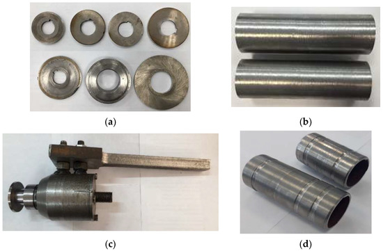
Figure 1.
Photos of the rotary tool, workpiece, and cup cutters used in the pre-processing process: (a) cup cutters (R6M5); (b) workpieces from bar Ø50 mm (Steel 45); (c) rotary tool; (d) workpieces from thick-walled pipe Ø72 mm (Steel 20Cr).
3. Results
In order to determine the durability time, the regression equation used will be x1—pre-processing time, min; x2—feed rate, mm/rev; x3—pre-processing speed, rpm.
The number of experiments is N = 23. The model is built in the form of the following dependence:
Y = b0+ b1 × x1 + b2 × x2 + b3 × x3
When planning experiments, the so-called coded values of the factors in question are used for simplification, and they do so with the help of some transformation:
where the natural value of the factor; —the interval of variation; the main level; —the coded value.
As a result, achieves values within , at the main level . Let us note the ranges of variation of the factors: x—the lower level; x—the upper level; i = 1, 2. Let us find the middle of these ranges—the primary levels [14,15]:
and the step of variation of the factor:
Substituting the values in (3) and (4), we obtain:
Let us write down the levels of variation in a simplified way: the upper level corresponds to +1, the lower to 1, and the main 0 (Table 1).

Table 1.
Levels of variation.
Let us fix the conditions of this experiment with the planning matrix (Table 2).
Table 2.
Planning matrix.
The results of determining the period of durability of cup cutters are shown in Table 3. To exclude the influence of random errors, not considering factors of the experiment, we will use the table of random numbers, writing out from it consecutive numbers in the number of experiments. These numbers determine the sequence of experiments [14], p. 125.
Table 3.
Values of the durability period after pre-processing.
The results of the experiments will help to find the sample coefficients b0, bi, and by, which can be estimated to find the theoretical regression coefficients β0, βi, and βy, i.e.,
Let us check the experimental data for the presence of gross errors. To determine gross errors, we use Student’s t-test.
where t is Student’s t-test; ttable is Student’s t-test taken at significance level α = 0.05 and the number of degrees of freedom f1; σ is root mean square error.
Let us calculate the variance of the experiment using the formula:
where N—number of experiments; n—number of repeated experiments.
The results of calculating line-by-line variance are shown in Table 4.
Table 4.
Linear variance.
We obtain the variance of the experiment:
Then, the root mean square error is:
Student’s t-test:
The tabulated value of Student’s test at a significance level of 0.05 and the number of degrees of freedom f1 = N(n − 1) = 8(3 − 1) = 16, ttable(0.05;16) = 2.12.
Comparing the tabulated value of Student’s t-test with the calculated:
Consequently, there are no gross errors in the experimental data.
Before proceeding, to determine the model of the experiment in the form of the regression equation, it is necessary to check the experiment’s reproducibility for the object under study. The reproducibility of the investigation is estimated with the Cochran criterion G. The experiment is considered reproducible if :
where Gtable is the tabular value of the Cochran criterion.
The table value of Cochran’s criterion is determined with the table depending on the number of degrees of freedom numerator p1 = m − 1 = 3 − 1 = 2, denominator ν2 = Ν = 8, and the chosen probability P. For technical calculations, take P = 0.95. If the reproducibility check of the experiment gives a negative result, the investigation is considered non-reproducible.
Given that 0.41 < 0.83, the condition of the Cochran criterion is fulfilled, and the experiment is considered reproducible. According to the planning matrix, we find the bi coefficients using the following formulas:
We calculate the model coefficients:
From these data, we derive a regression equation to determine the durability period:
T = 146.25 + 7.75x1 − 7x2 + 15.5x3
As well as determining the regression coefficients of these equations, we get an idea of the influence of the factors under study on the process, the interaction of the factors, and the direction of movement toward the optimum region. The problem is considered to be solved when the linear model falls into the area close to the optimum; otherwise, it is necessary to pass to polygons of higher powers to describe the optimum region adequately. Let us check the statistical significance of each model coefficient with Student’s test. For this purpose, we first of all calculate the variance of the coefficients:
From this, we obtain
The root mean square error of the model coefficients will be:
Consequently, we can construct a confidence interval:
where —the tabular value of Student’s test, = 2.01.
The coefficient is statically significant if its absolute value is greater than the interval, as
, which means ; , which means ; , which means ; , which means .
All coefficients are statically significant. The coefficients of the second equation are also statically significant.
Eventually, we check for adequacy of the obtained dependence; we find, based on experimental data, the variance of adequacy:
- where f1 = N − r is the degree of freedom;
- N—number of experiments;
- r—number of statistically significant coefficients.
f1 = 8 − 4 = 4.
Table 5.
Dispersion of model adequacy.
Based on the results in the table, let us determine the variance of adequacy with the number of degrees of freedom f1:
And also determine the variance of the experience with the number of degrees of freedom f2 = 8−1 = 7:
The hypothesis about the adequacy of the model is tested with Fisher’s criterion:
The table value of the Fisher criterion is taken at the significance level α = 0.05 and the number of degrees of freedom f1 and f2
Since the resulting model with a given confidence probability (95%) can be recognized as adequate and suitable for calculating the parameter T (durability period) in a given range of running conditions. Having obtained the adequacy of the accepted model (13), let us convert the coded values of the model into natural values using Formula (3):
As a result, we obtain the final model for determining the durability period:
T = 119.13 + 0.816t − 3.42S + 0.83nsp
The error of the regression model for determining the durability period of a cup cutter is less than 2%, which is quite acceptable.
Estimating the character and degree of influence of the considered factors shows that the most strongly influencing parameter is feed x2(S), at its increased value of the period increases. The next most effective is the pre-processing speed x3(nsp—spindle revolution), and the least influential is the running-in time x1(τp). The ranking of the factors makes it possible to adjust the considered parameters and build a more rational scheme of the technological process [16].
Experimental study on the pre-processing of cup cutters.
Figure 2 shows photos of the pre-processing process of cup cutters.
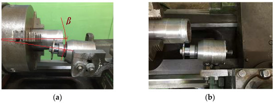
Figure 2.
Photos of the cup cutter pre-processing operation: (a) pre-processing operation using workpiece Ø50 mm of steel 45; (b) pre-processing process using workpiece Ø72 mm of steel 20X; β—angle of a cup cutter.
For the pre-processing of cup cutters, eight experiments were carried out, varying the values of the spindle revolution (nsp) and the duration (τd) of the pre-treatment. At the same time, the importance of the cup pick setting angle (β), feed (S), and cutting depth (t) remained constant.
Figure 3 shows the machined workpieces made of different materials during the pre-treatment of cup picks.
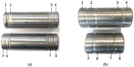
Figure 3.
Machined workpieces made of different materials during cup cutter pre-processing: (a) bars Ø50 mm of steel 45; (b) thick-walled pipes Ø72 mm of steel 20X; 1—nsp = 40 rpm (revolution per minute); 2—nsp = 80 rpm; 3—nsp = 20 rpm; 4—nsp = 12 rpm; 5—τd = 4 min; 6—τd = 3 min; 7—τd = 2 min; 8—τd = 1 min.
Figure 4 shows graphs showing the dependence of cup cutters’ durability period on the pre-processing regimes.
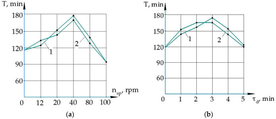
Figure 4.
Graphs of dependence of the durability period of cup cutters on the regimes of pre-processing: (a) graphs as a function of spindle speed; β = 100; S = 0.81 mm/rev; t = 0.5; τd = 3 min; (b) graphs as a function of durability time of cup cutters as a function of the duration of the preliminary break-in; 1—during processing steel 45; 2—during processing steel 20Cr; nsp = 40 rpm; β = 100; S = 0.81 mm/rev; t = 0.5.
From the diagram in Figure 4, it is visible that the increase in the frequency of rotation of a spindle up to 40 rpm positively influences the rise of value of the period of durability of a cup cutter. At nsp = 40 rpm, the maximum value of the cup cutters’ durability period (T = 170–178 min) is reached in the processing of workpieces from steels 45 and 20Cr.
Further increase in the spindle’s rotation frequency sharply decreases the values of the cup cutters’ durability period in the processing of workpieces from steels 20Cr and 45 (Figure 4a, curves 1, 2).
The influence of duration (time) of pre-processing also has a non-monotone character (Figure 4b). An increase in duration (time) of pre-processing up to 3 min promotes the growth of the durability period of cup cutters (up to T = 165–175 min) when machining workpieces from steels 45 and 20Cr. Further, an increase in the duration (time) of pre-processing influences the value of the period of durability of cup cutters (Figure 4b, curves 1, 2).
It is known that the hardness of the machined material during pre-processing also has an ambiguous effect on the durability period of the cutting tools, and the durability period decreases with increasing hardness [17,18]. This is also confirmed in our experiments (Figure 4a,b, curves 1, 2).
The modeling of the pre-processing.
The extreme character of the dependence of the pre-processing rate effect on the wear resistance of the tool contact surfaces, as well as the presence of the cutting speed limit (in our case 40 rpm) above which there is no effect of pre-treatment (Figure 4a,b), confirms the dominant role of deformation hardening in the secondary structure adaptation process.
In this regard, to test this issue, a simulation of the pre-burn-in process was carried out using the computer program ANSYS Workbench, and the problem was solved in a three-dimensional formulation. Applying software systems like ANSYS allows us not only to simulate of a complex cutting process with high reliability but also to visualize it in real time. Computer modeling is significantly more economical than cost-effective experimental studies and allows you to obtain several parameters of the cutting process that are not available for direct measurement.
Cutting with a cup cutter was simulated, and the size of the tool feed was taken into account due to the width of the cut. For the study, the pre-processing of the cup cutter in steel 45 and steel 20Cr processing was selected. As a result of modeling, stress and strain fields of the rolled material and the tool were obtained, and the thickness of the hardened layer of the cutting part of the cup cutter was compared when processing two types of steel.
Input data: nsp = 40 rpm; β = 100; S = 0.81 mm/rev; t = 0.5; τd = 3 min.
A plastic kinematic model (15), which is isotropic, a hardening kinematic model, or a combination of both with strain rate and fracture rate dependence, is used for modeling. The strain rate is taken into account using the Cowper–Symonds model, which scales the yield strength using the strain rate dependence coefficient [19,20].
- where —initial yield strength;
- —velocity of deformation;
- C and P—parameter of the velocity Cowper–Symonds deformation;
- —effective plastic deformation;
- —plastic hardening modulus (16).
Figure 5 shows the workpiece’s three-dimensional machining model and the mesh’s creation.
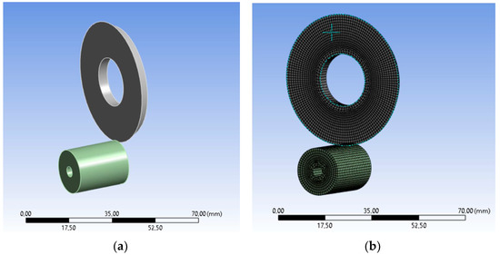
Figure 5.
Three-dimensional model of workpiece machining and mesh creation: (a) three-dimensional model; (b) mesh creation.
Figure 6 shows the hardening patterns of the cutting part of cup cutters when machining different materials.
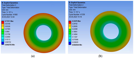
Figure 6.
Models of hardening of the cutting part of cup cutters during machining different materials: (a) during machining steel 45; (b) during machining steel 20Cr.
It is known that force and thermal processes during material cutting cause intensive plastic deformation of the contact surfaces of the cutting tool, leading to the development of secondary structures [21,22]. Secondary structures differ in form and properties from the original tool material, but these structures largely ensure the tool performance, productivity, and quality of machining [23,24]. The primary role in the developing of secondary structures during the contact interaction is played by the processes of generating various crystalline structure defects initiated by plastic deformation, proceeding against the background of high temperatures and their gradients.
The extreme character of the dependence of the wear resistance of the secondary structure on the cutting speed can be explained as follows. As the cutting speed increases, the sliding speed in the friction contact zone increases, leading to an increase in the rate and degree of plastic deformation of the contact layers of the tool. It leads to an increase in the density of crystalline structure defects, which determine the hardening value.
The optimum mode of pre-processing of the tool provides the best deformation and thermal conditions for hardening a cutting part of the tool. The research results have shown that after the pre-processing operation, a hardened layer is formed on the cutting part of the cup cutter (Figure 6). Depending on the hardness of the processed material, the thickness of the hardened layer varies. In the processing of steel 45, the thickness of the hardened layer of a cutter’s cutting part is 0.7 mm (Figure 6a), and in the processing of steel 20Cr, it is 0.3 mm (Figure 6b). It is revealed that with an increase in the hardness of processed material, the approached tool’s firmness decreases.
It is assumed that hardening is achieved by increasing the dislocation density. This case refers to hardening technologies based on purely deformational phenomena when, in the hardened zone, there are no sources of active chemical elements (for example, coatings or films) which could enter into metallographic interactions with the increasing density of crystalline structure defects, blocking the mobility of the latter [25]. The kinetics of this process, referred to as the uppermost layer, can be represented by the hypothetical dependencies graphically depicted in Figure 7.
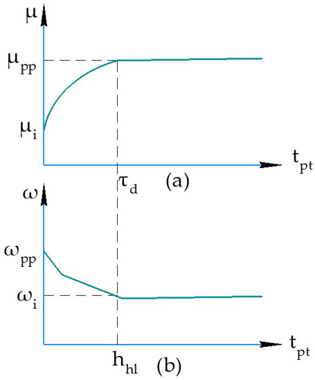
Figure 7.
Hypothetical kinematic characteristics of the tool pre-processing operation: (a) change of chemical potential; (b) presentation of wear intensity; μi, μpp—values of chemical potentials of initial and secondary contact structure; τd—duration of running-in period; hhl—thickness of hardened layer; tpt—processing time; ωi and ωpp—represent wear intensity of initial and running-in contact structure.
The dislocation interacts with the periodic field of the lattice as it moves along the sliding plane. The breaking and subsequent restoration of interatomic bonds accompany each elementary act of dislocation movement associated with overcoming the energy barrier. The resistance that a crystal lattice offers to dislocation displacement (lattice friction force or Payer’s stress) [26],
where crit—the stress necessary for the movement of a single dislocation and describes the resistance to dislocation movement from the lattice itself; G—the shear modulus; μ—the Poisson’s ratio; a—the spacing between planes; b—the distance between atoms in the shear direction.
The peculiarity of the pre-processing of the hardened tool is that its working surfaces already have an increased value of chemical potential in comparison with the primary tool material while possessing a lower energy absorption capacity or a complete absence of it. The intensity of the initial wear will naturally decrease in this case. The running-in process itself, in this case, may have three varieties depending on the internal energy state of the hardened surface structure [27,28]:
- The hardened surface structure still has the potential to absorb elastic internal energy.
- The strengthened surface structure is in a state of thermodynamically stable limiting saturation and cannot absorb elastic internal energy.
- The strengthened surface structure is in the state of thermodynamically unstable limiting saturation; it is unable to absorb elastic internal energy and seeks to get rid of it.
4. Discussion
The results of experimental studies of the pre-treatment process showed that the modes of running-in have an ambiguous effect on the durability period of cup cutters. Increasing the rotation frequency and duration of running-in time positively affects the durability period of cup cutters to a particular optimal value: nsp = 40 rpm; τd = 3 min. However, their further increase leads to a decrease in the durability period (Figure 4a,b, curves 1, 2).
It has been experimentally confirmed that the hardness of the machined material also affects the tool’s life period. With the increase in the hardness of the machined material, the value of the durability period of cup cutters decreases (Figure 4a,b, curves 1, 2). In the processing of steel 45, the value of the period of durability is T = 175–178 min, and in the processing of steel 20Cr, T = 165–170 min.
The ambiguous influence of the hardness of the processed material on the tool lifetime is confirmed with computer simulation results. In the processing of steel 45, the hardening of the cutting part of a cup cutter is 0.7 mm, and in the processing of steel 20Cr it is 0.3 mm.
5. Conclusions
The results of experimental studies of the pre-processing operation showed that, using the optimal modes of pre-processing (nsp = 40 rpm; β = 100; S = 0.81 mm/rev; t = 0.5; τn = 3 min), the durability period can be increased by 25–30 min.
The dependence for determining the durability period of cup cutters is derived. The influence of the hardness of the processed material on the tool’s durability period is confirmed, and it is established that the durability period decreases with the hardness increase. It is revealed that, with the increasing hardness of machined material, the durability period of a lapped tool decreases.
The results of computer modeling of the pre-treatment process confirmed the formation of a secondary contact structure due to intensive plastic deformation of the contact surfaces of the cutting tool.
Author Contributions
Conceptualization, K.S. and A.S.; methodology, Y.A. and Z.R.; software, A.S. and S.A.; validation, K.S.; formal analysis, S.A.; investigation, Y.A.; resources, B.M.; data curation, B.M., S.A., G.T. (Gulerke Tattimbek), G.T. (Gulim Tussupbekova), A.E. and Z.R.; writing—original draft preparation, K.S. and B.M.; writing—review and editing, K.S. and A.S.; visualization, K.S.; supervision, A.S.; project administration, A.S.; funding acquisition, A.S. and K.S. All authors have read and agreed to the published version of the manuscript.
Funding
This research is funded by the Science Committee of the Ministry of Science and Higher Education of the Republic of Kazakhstan (Grant No. AP14972884).
Data Availability Statement
Data are unavailable due to privacy or ethical restrictions.
Conflicts of Interest
The authors declare no conflict of interest.
References
- Mardonov, B.T.; Ravshanov, J.R. Investigation of Deformation-Thermal Processes in the Structural Adaptability of the Tool. Int. J. Adv. Res. Sci. Eng. Technol. 2021, 8, 18206–18209. [Google Scholar]
- Lebedev, V.Y. Influence of tangential movement of cutting blade on machining performance. J. Zhytomyr State Technol. Univ. Eng. 2017, 2, 84–91. [Google Scholar] [CrossRef]
- Abidi, Y. Analysis of the compromise between cutting tool life, productivity and roughness during turning of C45 hardened steel. Prod. Eng. Arch. 2021, 27, 30–35. [Google Scholar] [CrossRef]
- Kümmel, J.; Poser, K.; Zanger, F.; Michna, J.; Schulze, V. Surface layer states of worn uncoated and tin-coated wc/co-cemented carbide cutting tools after dry plain turning of carbon steel. Adv. Tribol. 2013, 2013, 519686. [Google Scholar] [CrossRef]
- Mardonov, B.T.; Ravshanov, Z.R. Research of kinematics of change of secondary contact structures of working surfaces of tooth-cutting tools. ISJ Theor. Appl. Sci. 2021, 11, 410–413. [Google Scholar] [CrossRef]
- Chernykh, I.K.; Vasil’ev, E.V.; Badamshin, A.M.; Kushnareva, A.G. Friction stir processing as a method of hardening cutting tools. J. Phys. Conf. Ser. 2022, 2182, 012046. [Google Scholar] [CrossRef]
- Sutjagin, A.V.; Trifanov, I.V.; Malko, L.S.; Majorova, A.N.; Oborina, L.I. Calculation of parameters of process and components of forces of cutting at rotational sharpen of the external screw surface by tool forcibly rotated multifluted on the basis of the accounting of the thermal stream, physical and geometrical parameters of shaving. Fundam. Res. 2013, 10, 2162–2168. [Google Scholar]
- Gik, L.A.; Shurygin, D.I. Development of universal designs for rotary cutting heads and tools. Russ. Eng. Res. 2009, 29, 1040–1042. [Google Scholar] [CrossRef]
- Rakishev, A.; Sagitov, A.; Donenbaev, B.; Sherov, K.; Tussupova, S.; Smakova, N.; Mazdubay, A.; Imanbaev, Y. Calculation of the multi-blade rotary-friction tool’s cutting cupped cutter to strength in the ansyswb surrounding. J. Appl. Eng. Sci. 2020, 18, 643–648. [Google Scholar] [CrossRef]
- Sherov, K.T.; Sikhimbayev, M.R.; Absadykov, B.N.; Balgabekov, T.K.; Zhakaba, A.D. Study of Temperature Distribution during rotary Turning of Wear-Resistant Cast Iron; News of the National Academy of Sciences of the Republic of Kazakhstan; Series of geology and technical sciences; National Academy of Sciences of the Republic of Kazakhstan: Almaty, Kazakhstan, 2022; Volume 2, pp. 271–282. [Google Scholar] [CrossRef]
- Binchurov, A.; Gordeev, Y.; Indakov, N. Method of Rotational Turning with Multifaceted Cutters. In IOP Conference Series: Materials Science and Engineering; IOP Publishing: Bristol, UK, 2016; Volume 124, pp. 12–15. [Google Scholar] [CrossRef]
- Sherov, K.T.; Mardonov, B.T.; Irzaev, A.; Karimov, S.A. Method of increasing wear resistance and reliability of worm mills. In Problems of Mechanics; Publishing House “Fan” Academy of Sciences of Uzbekistan: Tashkent, Uzbekistan, 2005; Volume 3, pp. 100–103. [Google Scholar]
- Mardonov, B.T.; Sherov, K.T.; Ravshanov, J.R.; Smailova, B.K. Research of influence of hardness of machining material on optimum speed of precharge. In Scientific Journal “Science and Technology of Kazakhstan”; Publishing House of PSU: Pavlodar, Kazakhstan, 2021; Volume 4, pp. 22–29. [Google Scholar]
- Adler, Y.P.; Markova, E.V.; Granovsky, Y.V. Experiment Planning in Finding Optimal Conditions; Nauka: Moscow, Russia, 1976; p. 279. [Google Scholar]
- Kadyrov, A.S.; Kadyrova, I.A. Fundamentals of Scientific Research; Karaganda State Technical University: Karaganda, Kazakhstan, 2015; p. 110. [Google Scholar]
- Mardonov, B.T.; Ravshanov, J.R. Investigation of microhardness in the contact layer of a worm cutter. In Strategy of modern Scientific and Technological Development of Russia: Problems and Prospects of Implementation. Collection of the IV All-Russian Scientific and Practical Conference; ICNP “New Science”: Petrozavodsk, Russia, 2021; pp. 27–31. [Google Scholar]
- Sherov, K.T.; Sagitov, A.A.; Userbaev, M.T.; Sherov, A.K.; Tusupbekova, G.M. Method of Increasing the Wear Resistance of Metal-Cutting Tools; Bulletin of the L.N. Gumilev ENU; Technical Sciences and Technologies Series; ENU Publishing House: Astana, Kazakhstan, 2022; pp. 141–149. Available online: https://bultech.enu.kz/index.php/main/article/view/321 (accessed on 1 June 2023).
- Sagitov, A.A.; Sherov, K.T.; Tusupbekova, G.M. Wear Resistance of Metal-Cutting Tools and Formation of Secondary Contact Structures during Cutting; Bulletin of the L.N. Gumilev ENU; Technical Sciences and Technologies Series; Astana: ENU Publishing House: Astana, Kazakhstan, 2022; pp. 87–97. [Google Scholar] [CrossRef]
- Dietenberger, M. Development of a High Strain-Rate Dependent Vehicle Model; Dietenberger, M., Buyuk, M., Kan, C.-D., Eds.; LS-DYNA Anwenderforum: Bamberg, Germany, 2005; pp. 1–10. [Google Scholar]
- Yang, C.T.; Kobayash, S. (Eds.) Mechanics of plastic deformation in metal processing. In Erich Gottfried Thomsen; Macmillan: New York, NY, USA, 1965; p. 486. [Google Scholar]
- Kim, V.A.; Yakubov, C.F. Dissipative structure of contact-friction interaction in metal cutting. Vestn. (Her.) Irkutsk. State Tech. Univ. 2018, 22, 35–45. [Google Scholar] [CrossRef]
- Kim, V.A.; Karimov, S.A. Manifestation of physical mesomechanics in contact interaction and wear. In Scientific Notes of the Crimean Engineering Pedagogical University; Crimean Engineering Pedagogical University: Simferopol, Ukraine, 2014; pp. 79–85. [Google Scholar]
- Kim, V.A.; Yakubov, F.Y.; Yakubov, C.F. Morphology of Contact Surfaces of High-Speed Cutting Tool during Turning of Titanium Alloy VT20. Scientific Notes. No II–2. 2016, pp. 56–63. Available online: http://www.uzknastu.ru/files/pdf/26/1/9.pdf (accessed on 1 June 2023).
- Mardonov, B.T.; Ravshanov, J.R. Investigation of the cutting process by the method of thermophysical analysis. In Academic Science as a Factor and Resource of Innovative Development Collection of Articles of the II International Scientific and Practical Conference; ICNP “New Science”: Petrozavodsk, Russia, 2021; pp. 79–83. [Google Scholar]
- Fedorov, S.V.; Aksenova, E. Synergetic Principle of Self-Organization under Friction; Bulletin of Science and Education of the North-West of Russia; “Russian Engineering Academy” Publishing House: Kaliningrad, Russia, 2017; Volume 3, pp. 21–41. [Google Scholar]
- Baranov, V.R.; Filippov, M.A. Physical Foundations of Hardening and Destruction of Materials: Textbook; Publishing House of Ural University: Yekaterinburg, Russia, 2017; p. 192. [Google Scholar]
- Yakubov, F.Y.; Kim, V.A. Structural and Energy Aspects of Hardening and Increasing the Durability of Cutting Tools; Crimean Educational and Pedagogical State Publishing House: Simferopol, Ukraine, 2005; p. 300. [Google Scholar]
- Grigoriev, C.N.; Tabakov, V.P.; Volosova, M.A. Technological Methods of Increasing the Wear Resistance of Contact Pads of Cutting Tools: Monograph; TNT: Stary Oskol, Russia, 2021; 380p. [Google Scholar]


Disclaimer/Publisher’s Note: The statements, opinions and data contained in all publications are solely those of the individual author(s) and contributor(s) and not of MDPI and/or the editor(s). MDPI and/or the editor(s) disclaim responsibility for any injury to people or property resulting from any ideas, methods, instructions or products referred to in the content. |
© 2023 by the authors. Licensee MDPI, Basel, Switzerland. This article is an open access article distributed under the terms and conditions of the Creative Commons Attribution (CC BY) license (https://creativecommons.org/licenses/by/4.0/).