


Rolling Eccentric Steel Rings on an Industrial Radial–Axial Ring Rolling Mill


Abstract
1. Introduction
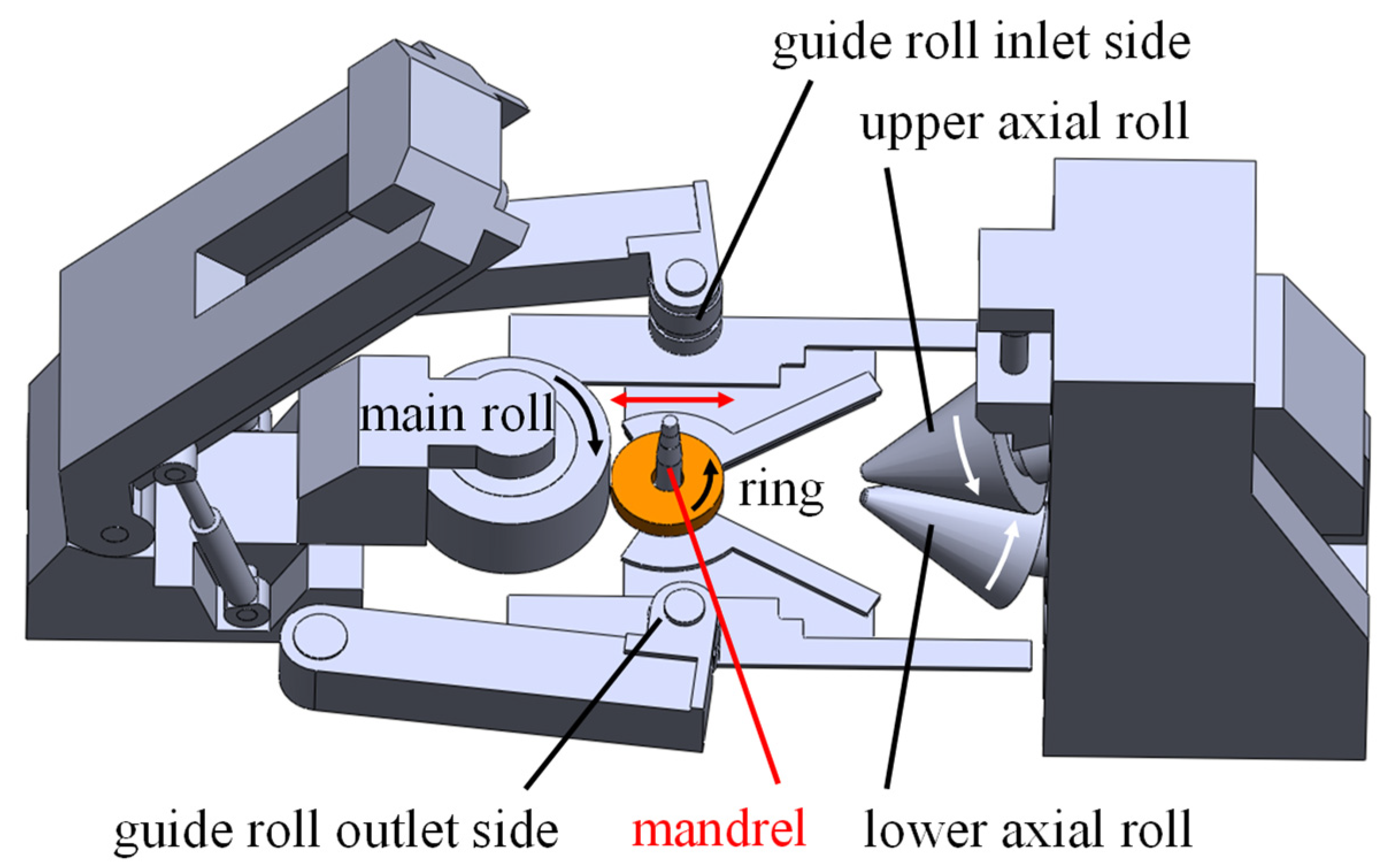
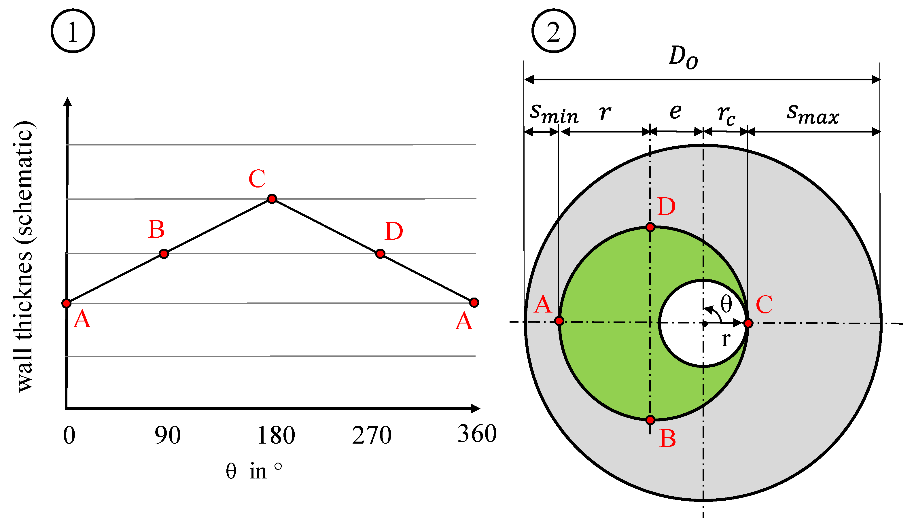
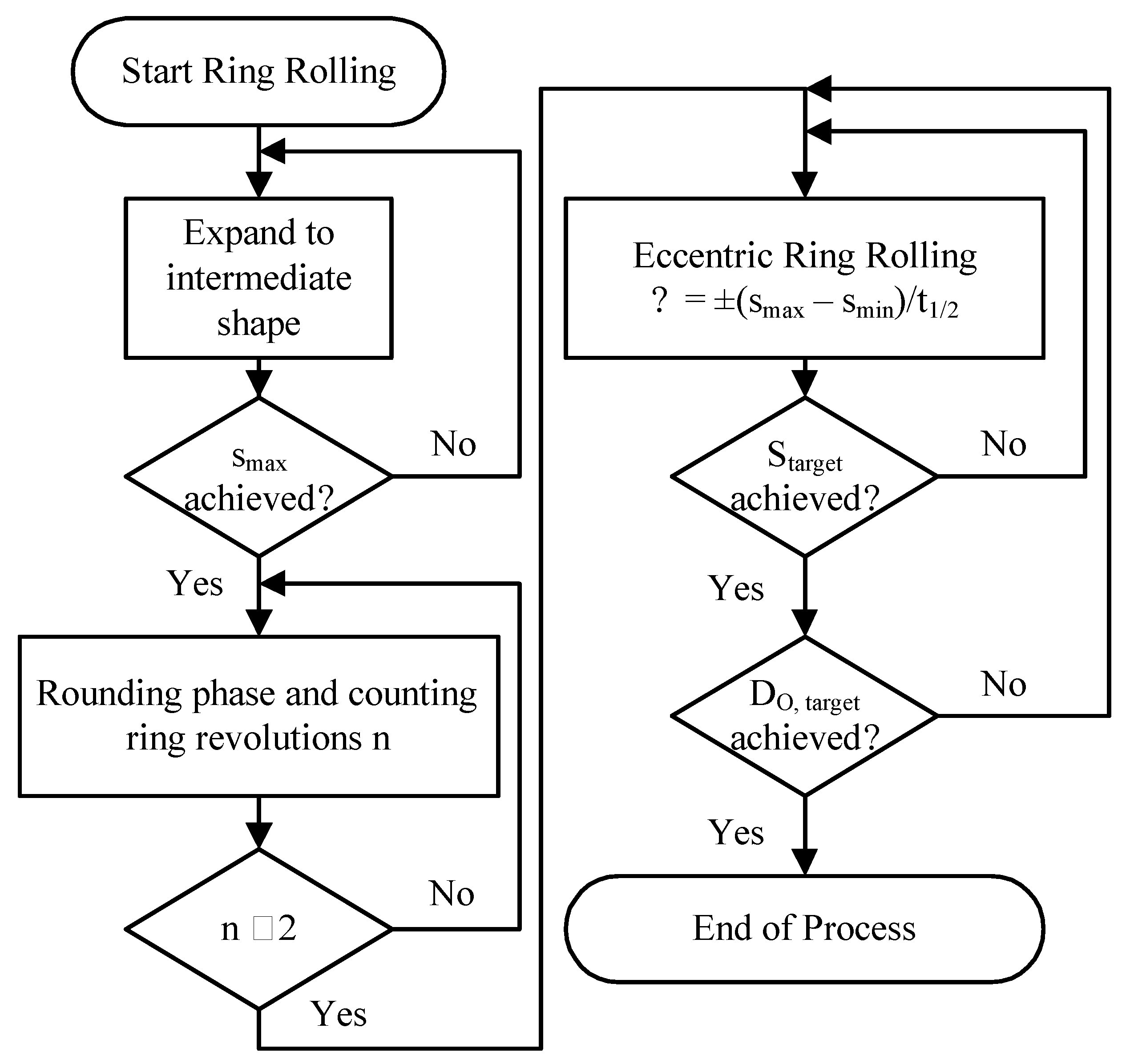
2. The Eccentric Ring Rolling Process
3. Procedure and Influences on Eccentric Ring Rolling
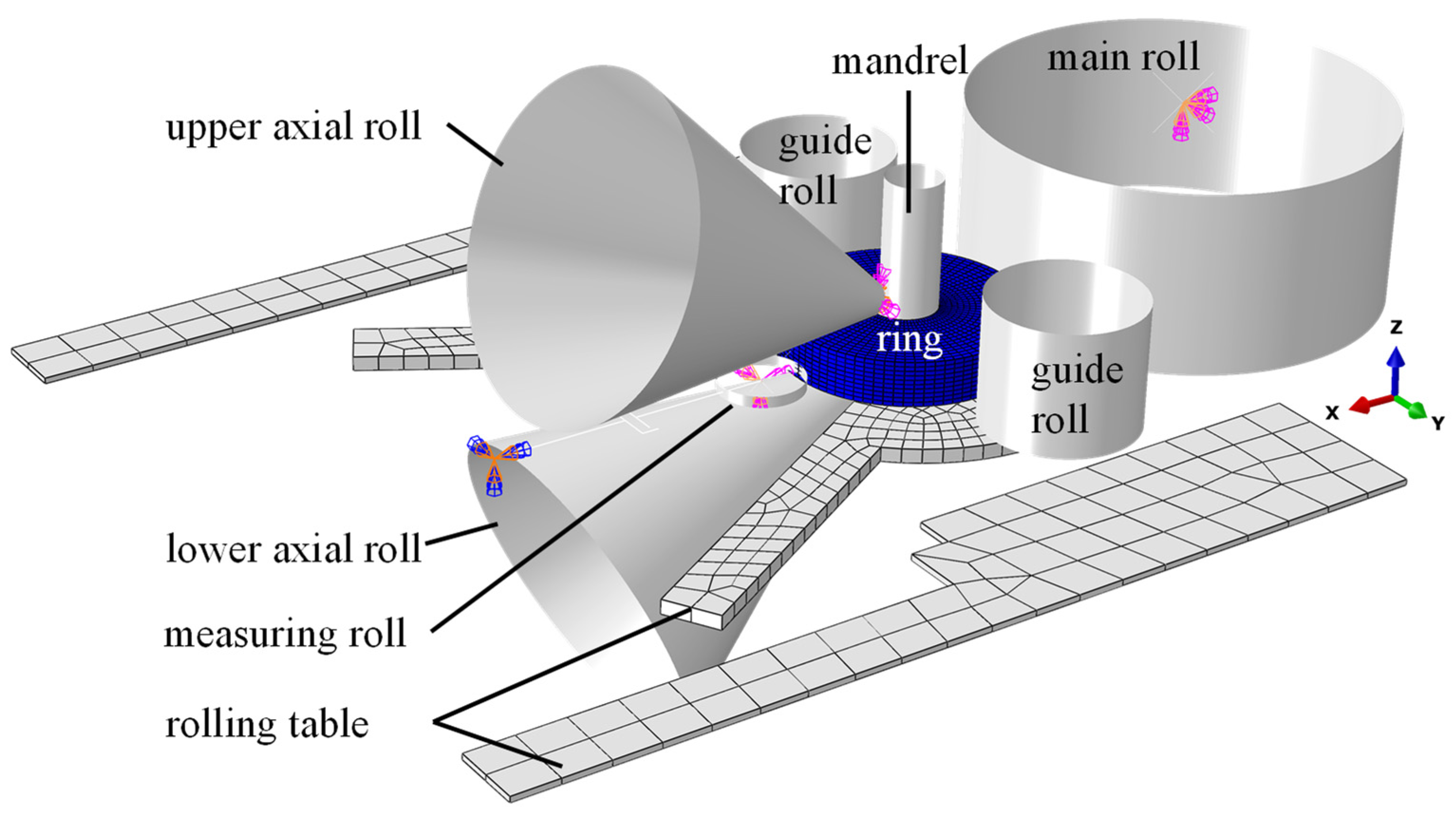
3.1. FEA Model for Developing the Ring Rolling Strategy
3.2. Influence Parameters to Be Considered
3.3. Process Parameters for Experimental Testing of the Eccentric Ring Rolling Strategy
4. Experimental Validation and Results
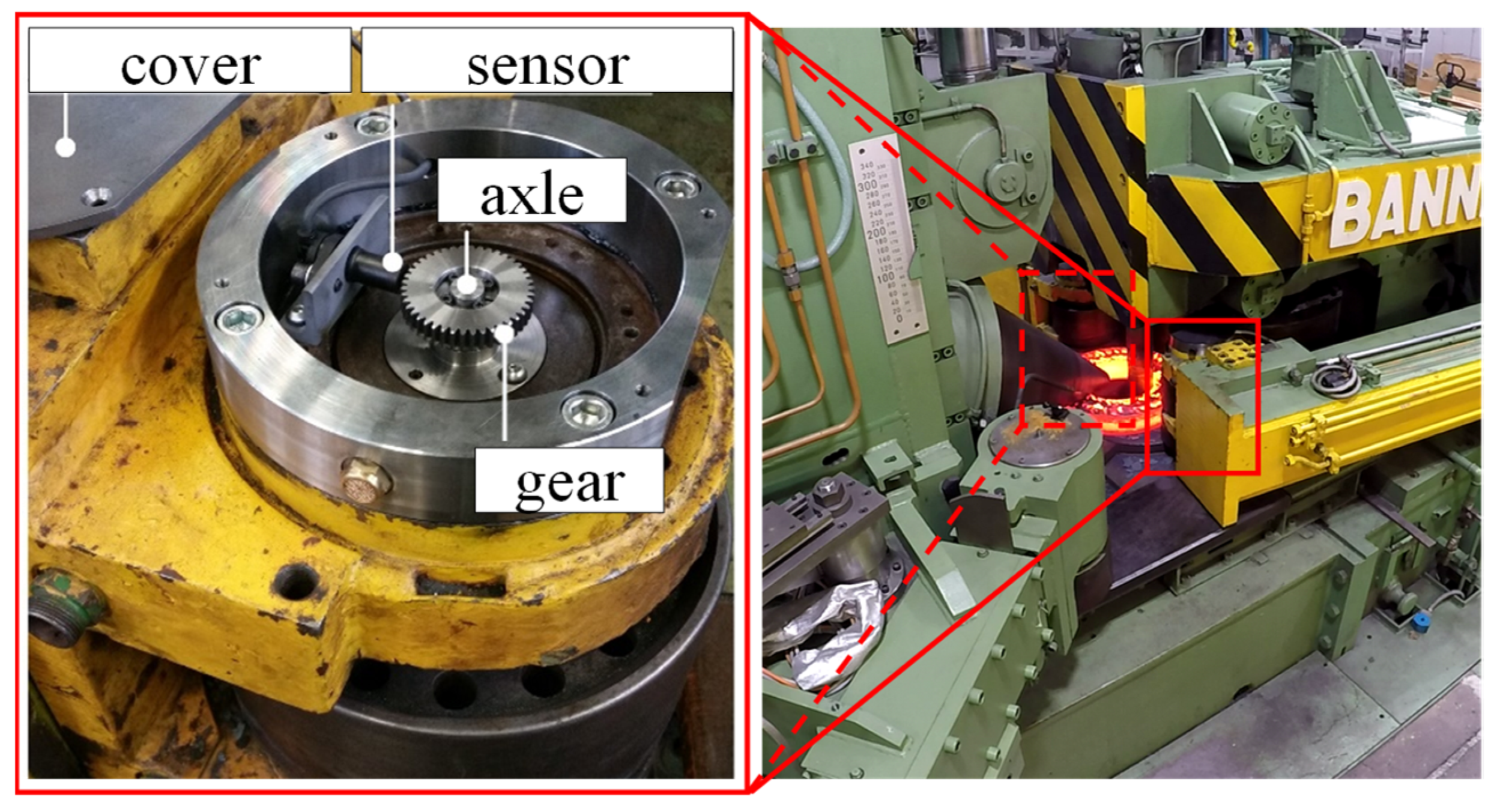
4.1. Experimental Set-Up
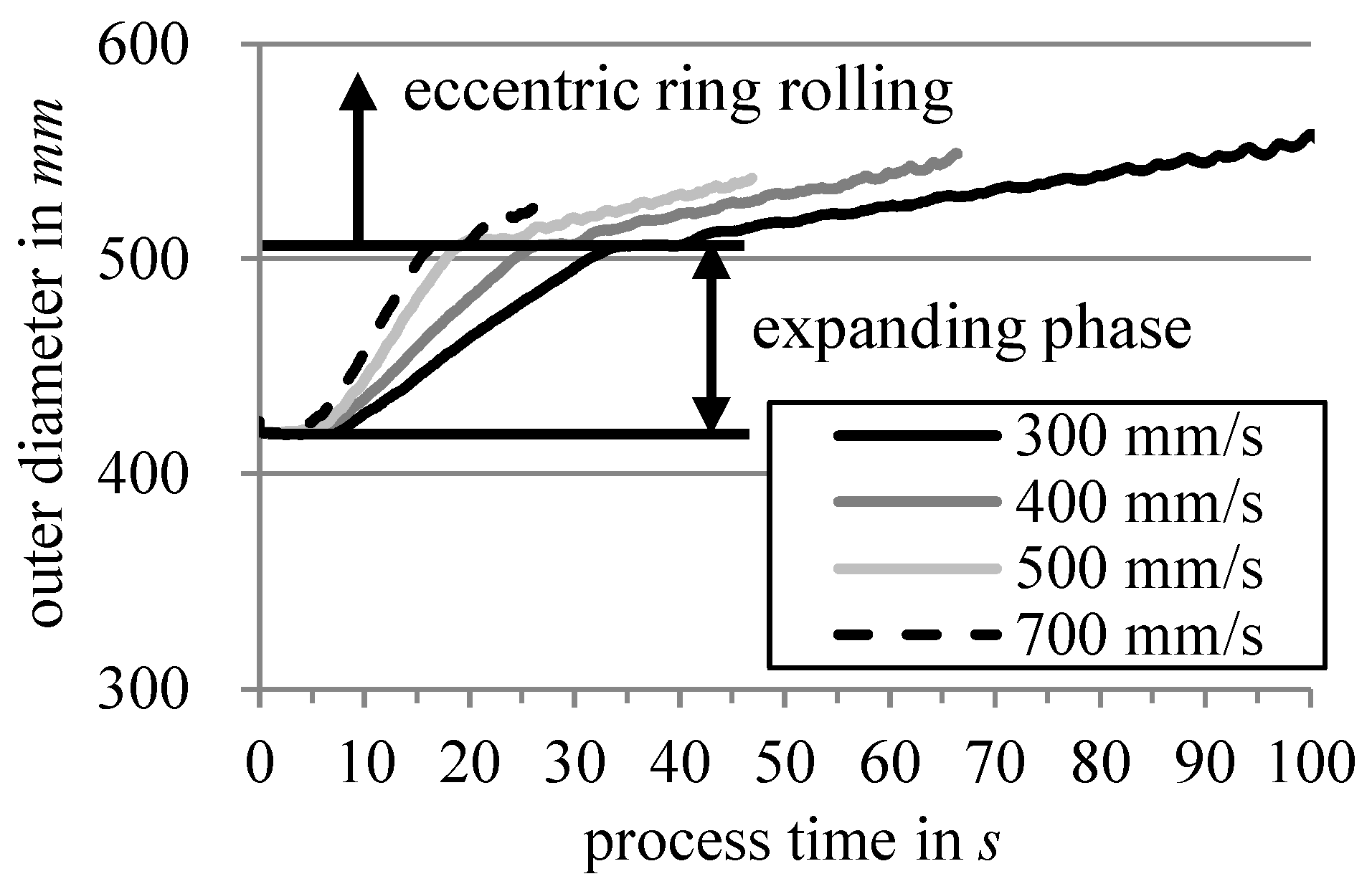
4.2. Validation Experiments of the Eccentric Ring Rolling Strategy
5. Conclusions and Future Research Opportunities
Author Contributions
Funding
Data Availability Statement
Conflicts of Interest
References
- Allwood, J.; Tekkaya, E.; Stanistreet, T.F. The development of Ring rolling technology. Steel Res. Int. 2005, 76, 111–120. [Google Scholar] [CrossRef]
- Lee, Y.S.; Lee, M.W.; Park, S.S.; Lee, I.; Moon, Y.H.; Lee, M.G. Process Design by FEM Simulation for Shape Ring Rolling of Large-Sized Ring. In Proceedings of the 10th International Conference on Numerical Methods in Industrial Forming, Pohang, Republic of Korea, 13–17 June 2010; pp. 964–971. [Google Scholar]
- de Souza, U.; Pursell, Z.; Phillips, K.; Vaze, S. Profile Ringrolling: New techniques have been developed to lower the cost and improve the buy-to-fly ratio of rings and cases in aerospace engines through advances in preform design and processing. Adv. Mater. Process. 2003, 161, 35–37. [Google Scholar]
- Keeton, C.R. Ring Rolling. In ASM International Metals HandBook VOL 14—Forming and Forging, 9th ed.; ASM International: Novelty, OH, USA, 1988; pp. 224–268. [Google Scholar]
- Cleaver, C.J.; Lohmar, J.; Tamimi, S. Limits to making L-shape ring profiles without ring growth. J. Mater. Process. Technol. 2021, 292, 117062. [Google Scholar] [CrossRef]
- Liang, L.; Guo, L.; Liu, Z.; Wang, P.; Zhang, H. On a precision forming criterion for groove-section profiled ring rolling process. J. Mater. Process. Technol. 2021, 296, 117207. [Google Scholar] [CrossRef]
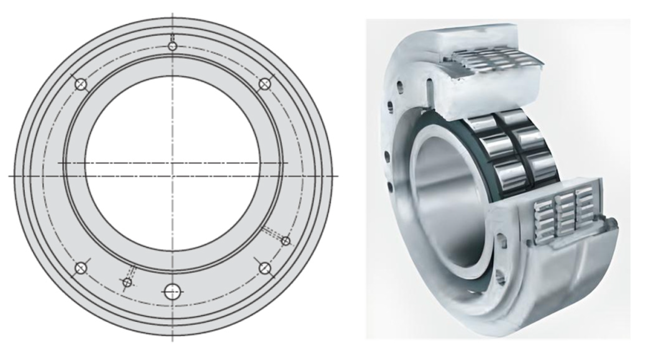
- FAG Industrial Bearings AG. FAG Triple Ring Eccentric Bearings in a Sheetfed Offset Press, 2003. Available online: https://www.schaeffler.com/remotemedien/media/_shared_media/08_media_library/01_publications/schaeffler_2/publication/downloads_18/wl_23502_de_de.pdf (accessed on 27 September 2023).
- Schaeffler Technologies GmbH & Co. KG. Genauigkeitslager Für Druckmaschinen, 2023. Available online: https://www.schaeffler.com/remotemedien/media/_shared_media/08_media_library/01_publications/schaeffler_2/tpi/downloads_8/tpi_222_de_de.pdf (accessed on 27 September 2023).
- Cleaver, C.J.; Arthington, M.R.; Mortazavi, S.; Allwood, J.M. Ring rolling with variable wall thickness. CIRP Ann. Manuf. Technol. 2016, 65, 281–284. [Google Scholar] [CrossRef]
- Arthington, M.R.; Havinga, J.; Duncan, S.R. Control of ring rolling with variable thickness and curvature. Int. J. Mater. Form. 2020, 13, 161–175. [Google Scholar] [CrossRef]
- Arthington, M.R.; Cleaver, C.; Allwood, J.; Duncan, S. Measurement and control of variable geometry during ring rolling. In Proceedings of the 2015 IEEE Conference on Control Applications (CCA), Sydney, Australia, 21–23 September 2015; IEEE: Piscataway, NJ, USA, 2015; pp. 1448–1454. [Google Scholar]
- Gröper, M.; Bailly, D.; Stergianou, S.; Hirt, G. Development of a measurement method for tracking the position of hot steel rings on an industrial radial-axial ring rolling mill. WGP Prod. Eng. 2023, 1–11. [Google Scholar] [CrossRef]
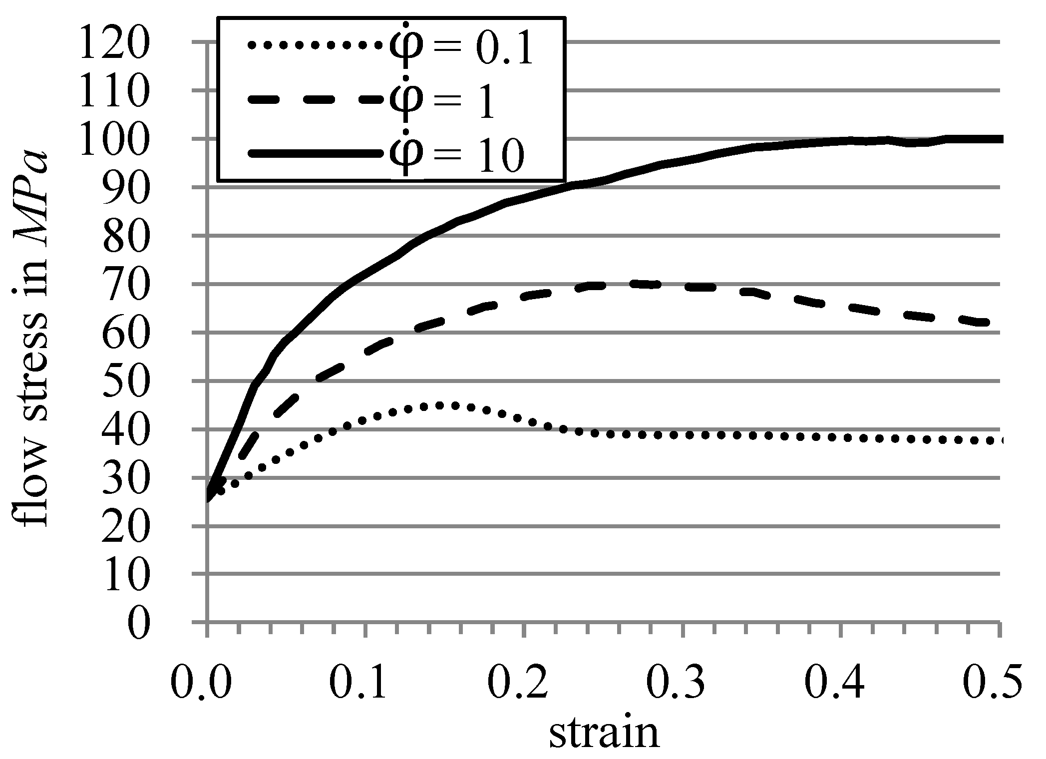
- Spittel, M.; Spittel, T. Steel symbol/number: S235JRG2/1.0038. In Metal Forming Data of Ferrous Alloys—Deformation Behaviour, 2C1; Martienssen, W., Warlimont, H., Eds.; Landolt-Börnstein-Group VIII Advanced Materials and Technologies; Springer: Berlin/Heidelberg, Germany, 2009; pp. 126–131. [Google Scholar]
- Jenkouk, V.; Hirt, G.; Franzke, M.; Zhang, T. Finite element analysis of the ring rolling process with integrated closed-loop control. CIRP Ann. Manuf. Technol. 2012, 61, 267–270. [Google Scholar] [CrossRef]
- Jenkouk, V.; Hirt, G.; Franzke, M. 3D-FE simulation of ring rolling with integrated closed-loop tool motion control. In Proceedings of the ICRF 2012, 1st International Conference on Ingot Casting, Rolling and Forging, Aachen, Stahleisen, Düsseldorf, Germany, 18–21 April 2012. [Google Scholar]
- Kopp, R.; Koppers, U.; Wiegels, H. New Control System for Ringrolling. Adv. Technol. Plast. 1987, 2, 803–807. [Google Scholar]
- Hawkyard, J.B.; Johnson, W.; Kirkland, J.; Appleton, E. Analyses for roll force and torque in ring rolling, with some supporting experiments. Int. J. Mech. Sci. 1973, 15, 873–893. [Google Scholar] [CrossRef]
- Kopp, R. (Ed.) Umformtechnik Stahl und NE-Werkstoffe Visionen und innovative Lösungen. In Proceedings of the 19. ASK, Aachener Stahlkolloquium, Aachen, Germany, 25–26 March 2004; Eurogress Aachen Tagungsband, Verlag Mainz: Aachen, Germany, 2004. [Google Scholar]


| Type | ||||
|---|---|---|---|---|
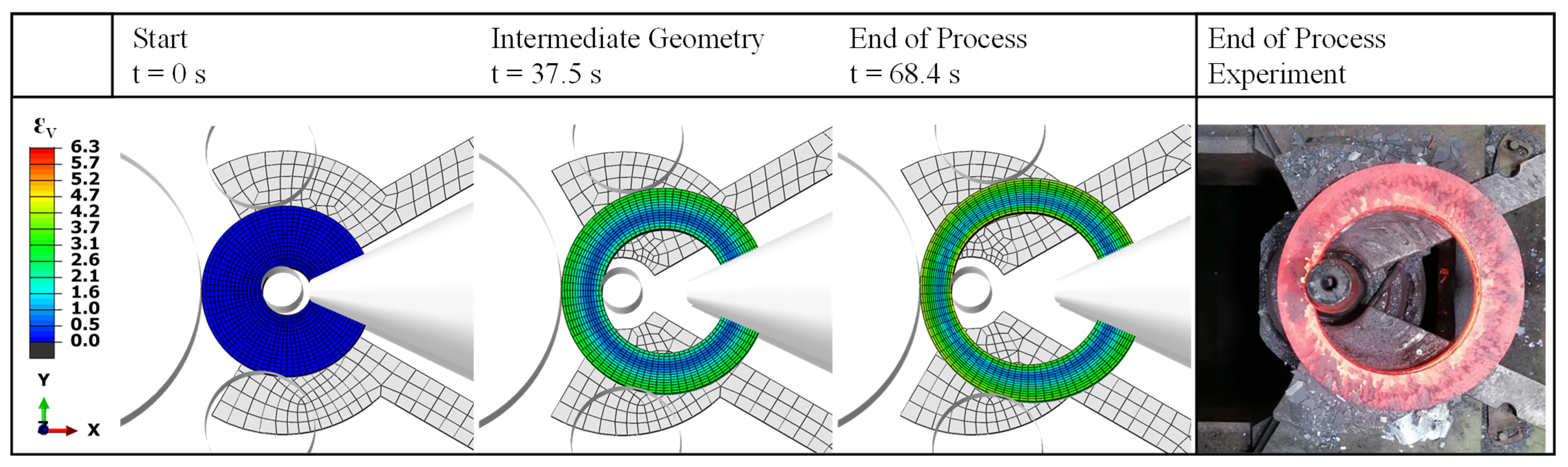
| Start | 420 mm | 120 mm | 150 mm | 80 mm |
| Intermediate | 506 mm | 120 mm | 99.6 mm | 80 mm |
| Element Type | C3D8RT (ALE-Adaptive Mesh) |
|---|---|
| number of elements | ≈15.000 |
| emissivity | ε = 0.8 |
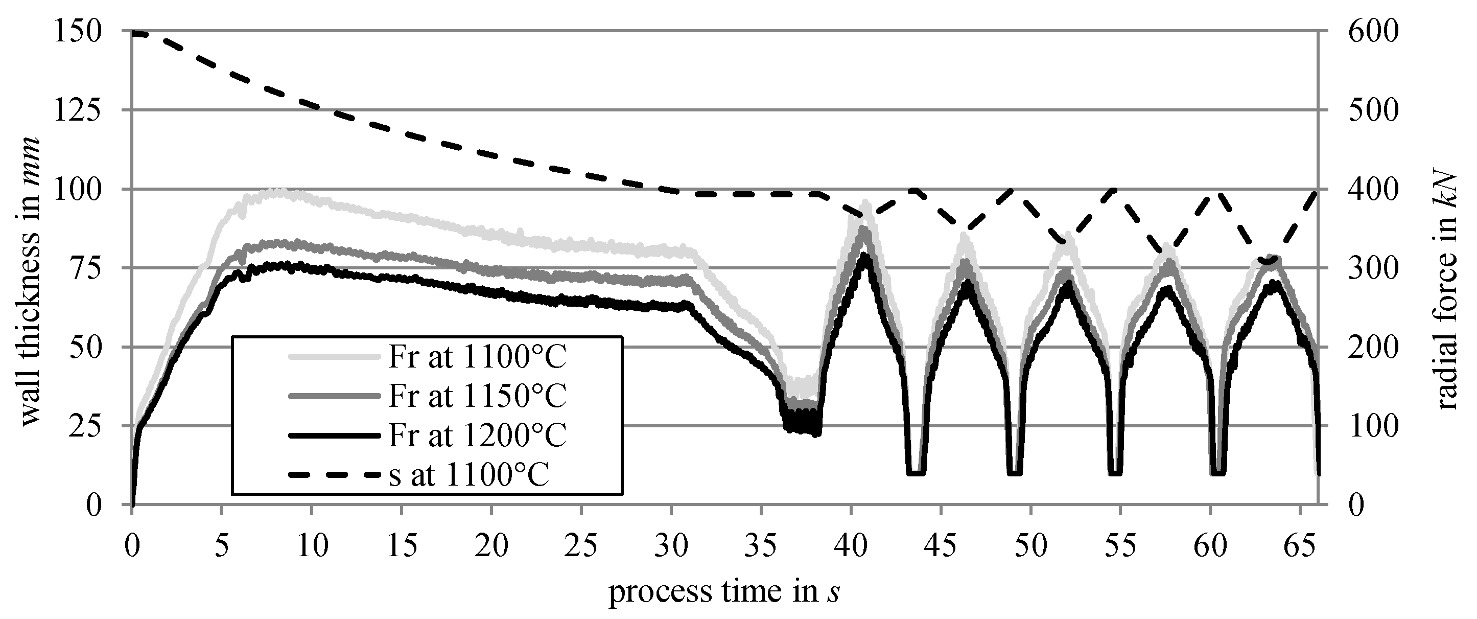
| initial ring temperatures | ϑRing = 1100, 1150, 1200 °C |
| mass scaling (by factor) | 250 |
| tool temperature | ϑtool = 200 °C |
| material (yield stress) | ST 37-2 ,) |
| Young’s modulus | E = (ϑ) ≈ 213 kN/mm2 at 1200 °C |
| Poisson’s ratio | ν = f(ϑ) ≈ 0.34 |
| density | ρ = f(ϑ) ≈ 7430 kg/m³ at 1200 °C |
| heat capacity | cp = f(ϑ) ≈ 314 J/(kg K) at 1200 °C |
| thermal conductivity | λ = f(ϑ) ≈ 39 W/(m K) at 1200 °C |
| Tool | Dimension |
|---|---|
| main roll: | |
| diameter | Dmr = 748 mm |
| height | hmr = 330 mm |
| mandrel diameter | Dmd = 100 mm |
| guide rolls diameter | Dgr = 270 mm |
| axial rolls: | |
| half opening angle | β = 22.5° |
| slant height of the truncated cone | mar = 670 mm |
| missing peak | par = 75 mm |
| Tools’ Motions | Description |
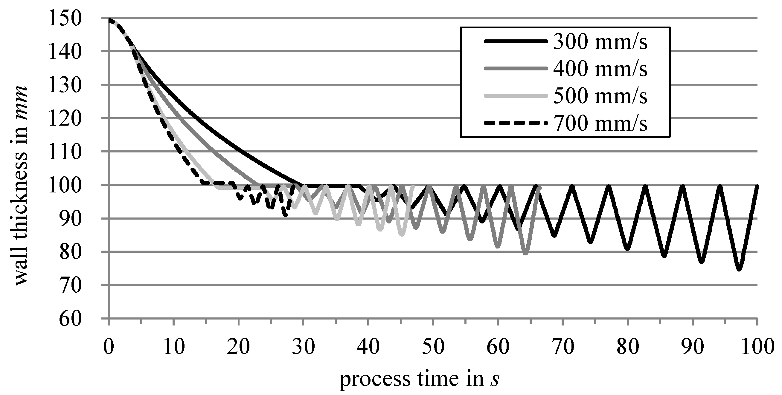
| Main roll circumferential velocity | Is kept nearly constant during ring rolling Varied between 300 and 700 mm/s |
| Radial mandrel velocity | Is kept nearly constant until the rounding phase Dynamic feeding in the eccentric rolling phase |
| Motion of both guide rolls | Is symmetrically controlled in a closed loop depending on the outer ring diameter and stabilization force (see [12,15]) |
| Rotational speed of both axial rolls | Is controlled in a closed loop Both rolls operate with the same rotational velocity Rotational velocity is based on the main rolls’ circumferential velocity and the other diameter of the ring (see [14]) |
| Motion of the axial rolls in radial direction | Motion depends on the outer diameter of the ring |
| Vertical motion of the upper axial roll | No movement; ring height is kept constant |
| Main Roll Circumferential Velocity | Process Time | ||
|---|---|---|---|
| 300 mm/s | 74.6 mm | 98.4 mm | 100 s |
| 400 mm/s | 79.4 mm | 98.9 mm | 54 s |
| 500 mm/s | 85.1 mm | 98.1 mm | 47 s |
| 700 mm/s | 91.0 mm | 99.4 mm | 28 s |
| Type | ||||||
|---|---|---|---|---|---|---|
| FEA | 552 mm | 380 mm | 74.6 mm | 98.4 mm | 80.0 mm | 11.9 mm |
| Experiment no. 1 | 554.5 mm | 381 mm | 74.9 mm | 97.9 mm | 80.0 mm | 11.5 mm |
| Deviation FEA/Experiment no. 1 | 0.45% | 0.26% | 0.4% | 0.51% | - | 3.47% |
| Experiment no. 2 | 554.5 mm | 380 mm | 75.0 mm | 97.8 mm | 80.0 mm | 11.5 mm |
| Deviation FEA/Experiment no. 2 | 0.45% | - | 0.53% | 0.61% | - | 3.47% |
| Experiment no. 3 | 554.5 mm | 381 mm | 75.2 mm | 97.9 mm | 80.0 mm | 11.4 mm |
| Deviation FEA/Experiment no. 3 | 0.45% | 0.26% | 0.79% | 0.51% | - | 4.39% |
| Experiment no. 4 | 555.4 mm | 379.5 mm | 75.4 mm | 97.7 mm | 80.0 mm | 11.2 mm |
| Deviation FEA/Experiment no. 4 | 0.61% | 0.13% | 1.06% | 0.72% | - | 6.25% |
| Experiment no. 5 | 554.3 mm | 376.5 mm | 75.2 mm | 97.9 mm | 80.0 mm | 11.4 mm |
| Deviation FEA/Experiment no. 5 | 0.41% | 0.93% | 0.79% | 0.51% | - | 4.39% |
Disclaimer/Publisher’s Note: The statements, opinions and data contained in all publications are solely those of the individual author(s) and contributor(s) and not of MDPI and/or the editor(s). MDPI and/or the editor(s) disclaim responsibility for any injury to people or property resulting from any ideas, methods, instructions or products referred to in the content. |
© 2024 by the authors. Licensee MDPI, Basel, Switzerland. This article is an open access article distributed under the terms and conditions of the Creative Commons Attribution (CC BY) license (https://creativecommons.org/licenses/by/4.0/).
Share and Cite
Gröper, M.; Quadfasel, M.; Bailly, D.; Hirt, G. Rolling Eccentric Steel Rings on an Industrial Radial–Axial Ring Rolling Mill. J. Manuf. Mater. Process. 2024, 8, 75. https://doi.org/10.3390/jmmp8020075
Gröper M, Quadfasel M, Bailly D, Hirt G. Rolling Eccentric Steel Rings on an Industrial Radial–Axial Ring Rolling Mill. Journal of Manufacturing and Materials Processing. 2024; 8(2):75. https://doi.org/10.3390/jmmp8020075
Chicago/Turabian StyleGröper, Mirko, Marten Quadfasel, David Bailly, and Gerhard Hirt. 2024. "Rolling Eccentric Steel Rings on an Industrial Radial–Axial Ring Rolling Mill" Journal of Manufacturing and Materials Processing 8, no. 2: 75. https://doi.org/10.3390/jmmp8020075
APA StyleGröper, M., Quadfasel, M., Bailly, D., & Hirt, G. (2024). Rolling Eccentric Steel Rings on an Industrial Radial–Axial Ring Rolling Mill. Journal of Manufacturing and Materials Processing, 8(2), 75. https://doi.org/10.3390/jmmp8020075