Abstract
Strategies for obtaining deep slots in soft materials can vary significantly. Conventionally, the tool travels along the slot, removing material mainly with the side cutting edges. However, a “plunge milling” strategy is also possible, performing the cut vertically, taking advantage of the tip cutting edges that almost reach the center of the tool. Although both strategies are already commonly used, there is a clear gap in the literature in studies that compare tool wear, surface roughness, and productivity in each case. This paper describes an experimental study comparing the milling of deep slots in AA7050-T7451 aluminum alloy, coated with a novel DLCSiO500W3.5O2 layer to minimize the aluminum adhesion to the tool, using conventional and plunge milling strategies. The main novelty of this paper is to present a broad study regarding different factors involved in machining operations and comparing two distinct strategies using a novel tool coating in the milling of aeronautical aluminum alloy. Tool wear is correlated with the vibrations of the tools in each situation, the cycle time is compared between the cases studied, and the surface roughness of the machined surfaces is analyzed. This study concludes that the cycle time of plunge milling can be about 20% less than that of conventional milling procedures, favoring economic sustainability and modifying the wear observed on the tools. Plunge milling can increase productivity, does not increase tool tip wear, and avoids damaging the side edges of the tool, which can eventually be used for final finishing operations. Therefore, it can be said that the plunge milling strategy improves economic and environmental sustainability as it uses all the cutting edges of the tools in a more balanced way, with less global wear.
1. Introduction
The design of many aerospace parts presents very interesting machining challenges. The need to machine deep slots in soft materials is quite common, a situation that becomes even more challenging for machining processes when the resulting walls are relatively thin. If the geometry is very complex, robotic systems can even be used to execute these shapes through multi-axis machining [1]. For straight slots, conventional CNC machining is perfectly adequate, but it can be carried out using different strategies, although the surface roughness is a challenge to consider [2,3]. In fact, for the geometries of some complex parts applied in turbomachinery, electrical discharge machining can be more advantageous than chip-removing machining due to such complexity, the inherent difficulty of implementation, and the risk of obtaining surfaces with high roughness [4,5].
Slotting operations are an absolute necessity in the manufacture of countless components for various types of industries, and milling or grinding is often used to create slots in several materials [6]. The geometry of each slot influences the milling time to obtain the desired shape, the type of tool coating, and the machining strategy used. The mechanical properties of the material to be machined influence the surface roughness characteristics, productivity, and tool wear and demand attention to environmental issues, enforcing the use of more environmentally friendly lubrication/cooling products [7,8].
1.1. Slot Milling
Slot milling has been frequently studied. This technique is challenging, presenting different problems. Rodriguez-Alabanda et al. [9] focused on a trochoidal strategy and variable helix-angle tool to make deep slots in AW 2024-T3 aluminum alloys. The authors tried to take advantage of the higher heat dissipation typically obtained using this milling strategy (intermittent cutting), decreasing the cutting forces developed and removing greater amounts of material without excessive tool effort and wear. The authors pointed out cutting speed (Vc) and feed/tooth (fz) as the most influential parameters to induce a higher material removal rate (MRR), while machined surface roughness was essentially conditioned by the radial depth of cut (ae) and feed/tooth (fz). The developed model allows for optimizing MRR (error, as the most influential parameter to induce higher material removal rate (MRR), less than 5%) and surface roughness (error less than 10%). Also taking advantage of the benefits offered by the trochoidal machining strategy, Li et al. [10] developed a computational technique to evolve this strategy from a 2D methodology to a 3D approach in five-axis machining centers. The strategy developed aims to create slots with a non-rectilinear profile. Considering the estimated cutting force, the computational application differs in the depth of the layer to be machined, avoiding excessive effort on the tool and minimizing its wear, while optimizing the tool path and the time required for machining. Niknam and Songmene [11] studied burr formation in slotting 6061-T6 and 2024-T351 aluminum alloys, which affects the surface quality. Thus, to mitigate the burr formation problem, these authors proposed a computational algorithm that allows calculating the friction angle λ corresponding to each material, considering the specific levels of cutting speed, feed per tooth, and thickness of the undeformed chip. It was proven that a smaller angle λ is obtained when a higher chip load is used. Conversely, a larger angle λ will be obtained when the exit up-milling-side chip thickness decreases and the exit bottom chip thickness increases. Vogtel et al. [12] tested the effectiveness of different compositions of cemented carbides in slotting Inconel 718 alloy. It was possible to observe that WC-10Co tools showed better performance in terms of fracture toughness and abrasion resistance than WC-6Co tools. WC-10Co tools allowed a much higher feed rate (fn = 0.075 mm/rev) for Vc = 20 m/min cutting speeds, instead of the Vc = 2–5 m/min allowed by the HSS tools. Jaeger et al. [13] created a model to predict forces when milling AISI 316L stainless steel thin walls (a common situation when opening slots) of components obtained by selective laser sintering. The model created predicts higher machining forces than those reported in experimental tests, leading to the need for fine-tuning the model. Also, cutting fluids have been studied in slot milling. Gueli et al. [14] studied tool wear, cutting forces, and surface roughness of Inconel 718 in slot milling operations with and without flood coolant. For the same cutting conditions, tools used with flood coolant showed increased wear on the back and rake faces, inducing higher surface roughness. Flood coolant was confined to a very conservative parameter in terms of the depth of cut and feed rate. Bagherzadeh et al. [15] investigated the effect of using ecological lubricants on the surface quality of the machined part, cutting forces, tool wear, and temperature developed when milling slots in titanium alloys. Thus, several cooling combinations were used, such as cryogenic cooling by spraying liquid nitrogen, cryogenic cooling by spraying carbon dioxide, a mix of spraying carbon dioxide and a minimum quantity of lubrication, and spraying liquid nitrogen together with a minimum quantity of lubrication. It was found that cryogenic cooling presents better performance for high cutting speeds. It was also reported that the simultaneous use of cryogenic fluid and a minimum quantity of lubrication significantly increased the machinability of the titanium alloy due to the combined effect of cooling and lubrication. Osman et al. [16] used minimum quantity lubrication (MQL) with different concentrations of hexagonal boron nitride (hBN) nanoparticles in slotting titanium alloys, aiming to reduce both the surface roughness and the cutting force. The feed rate was the most influential parameter in the variation in the cutting forces and the surface roughness. The authors reported that increasing the depth of cut leads to a degradation of surface quality and an increase in cutting forces, but this can be improved by a greater concentration of nanoparticles fed to the cutting area. The combined effect of hBN nanoparticles and MQL is a very effective solution in reducing the heat developed in the cutting zone. These and many other works allow us to conclude that special attention needs to be paid to slotting operations in any material, with particular emphasis on Al alloys.
1.2. Milling Strategies
Machining strategies have been discussed in many machining studies, and some very interesting results have been reported. Based on the study of an aluminum alloy 7075-T651, Pleta et al. [17] compared the slotting strategy with trochoidal milling in terms of the development of cutting forces during the slotting process. They concluded that using the same feed per tooth in both strategies, the tangential cutting force resulting from the developed models is relatively accurate when compared with models based on the chip thickness geometries in both strategies regarding the same model. Global strategy must be defined in the earlier stage when using CAD/CAM software, as mentioned by Dodok et al. [18], who used several experimental numerical control (NC) strategies to accelerate the CNC code generation process based on the use of EdgeCAM software, saving time in the preparation and milling processes. Vila et al. [19] developed a model to determine the best machining strategy to minimize energy consumption (less CO2 emission) and maximize the quality of the machined surface. To minimize pocket milling time in the aerospace industry, Gaur and Law [20] used combined mode and feed-direction-dependent stability criteria. The combined mode considers the influence of pre-existing slots to determine the tool’s rising and falling needs during milling, while feed-direction-dependent stability tries to take advantage of the tool’s dynamics in different directions to determine the limit to which the process manages to preserve the maximum cutting stability. The model allowed productivity gains of 60%. Pal et al. [21] developed a methodology to implement a feature-based machining process, departing from the CAD design of complex parts, allowing the interactive management of different features (intersecting volumes) and establishing more productive machining strategies that generate less wear on tools. The model offers better-quality machined surfaces and increased modularity. Zhang et al. [22] developed a methodology to efficiently define the milling tool path based on a Markov decision process, thereby allowing the adoption of deep reinforcement learning. Convolutional graph neural networks were used to improve the processing of graphs as neural networks underlying the methodology. After training, the developed methodology proved to be capable of generating efficient machining paths in compliance with the machining process rules. The study was successfully validated using parts for the aeronautical industry. In a related work using the same methodology, the same team [23] reports that, after training, the model revealed an accuracy of 93.31% in predicting process routes for machining features, thus showing its high effectiveness. Given the accentuated wear usually presented by ball-end tools, and considering the theory of uniform wear, Guo et al. [24] developed a continuous oscillating milling strategy, which aims to dynamically adjust the oscillating angle of the tool axis, promoting a reduction in wear and thus significantly prolonging the useful life of the tool. Wagih et al. [25] developed an elliptical tool path in a trochoidal milling strategy to improve the material removal rate and surface quality. A model was developed to correlate the maximum chip thickness with the cutting forces. The experimental validation of the model allowed an error lower than 11% in predicting the waviness of the slot walls, modeled based on the geometry of the cutting tool path. At the same time, an improvement in the material removal rate of 11% was achieved, while a slight reduction in the resulting maximum cutting force of 3% was also observed. On the other hand, wall waviness and surface roughness increased by 45% and 38%, respectively, compared with the typical true trochoidal tool path. Such work shows that these strategies are very important in aluminum slotting.
1.3. Milling AA750 Aluminum Alloy
The aluminum alloy 7050-T7451 has been widely studied according to different manufacturing processes, as this alloy is commonly applied in the aeronautical industry [26,27]. Based on high-speed machining (HSM), Wang and Liu [28] studied the acoustic emission signals emitted during chip formation to understand the mechanism behind material separation under the effect of the cutting tool, verifying that serrated chip formation contributes significantly to a greater amplitude of the emitted signal, resulting in continuous and bursting signals being obtained. Ping et al. [29] also investigated the HSM of 7050-T7451 alloys, developing a model based on AdvantEdge which, based on traditional milling parameters such as cutting speed, feed, depth of cut, and tool geometry, intended to predict the temperature and forces developed in the tool. Differences in the behavior of the XX’ and YY’ axes were observed over the machining time, and it was noted that the temperature initially increased but then decreased once a certain cutting speed was reached. Perez et al. [30] studied the influence of cutting speed on the surface roughness of parts machined from 7050-T7451 aluminum alloy. These authors did not report significant differences in terms of the surface roughness and the appearance of microstructural defects with variations in cutting speed. However, an increase in cutting speed resulted in an increase in residual stresses and the layer affected by the deformation/cutting process on the surface. Chang et al. [31] suggested the use of cemented carbide tools of fine grain and increased toughness as they found that the main failure mechanisms in milling high-strength aluminum alloys were tool fracture, excessive wear, and vibration in the cutting process. The main causes identified for these effects were the bending moment prompted by dynamic unbalance and tool vibration, which induce premature fatigue. A similar study presented by Berry et al. [32] demonstrated that an increase in feed per tooth in combination with a reduction in cutting speed induces an increase in the compressive residual stress on the surface of the material, which improves the fatigue life of the machined components, although the tools deteriorate more easily. On the other hand, they stated that increasing the cutting speed reduces the residual stresses installed on the surface, while an increase in the feed per tooth induces a higher level of residual stresses. Kechagias [33] carried out a generic study that encompassed several machining parameters, trying to optimize them when milling AA 5083 aluminum alloy, essentially aiming to improve tool life and the condition of the machined surface. On the other hand, Fountas et al. [34] carried out a study more focused on the aeronautical industry, with a view to optimizing the planning of machining operations through programmable support functions, with a view to shortening and improving the connection between the design phases and machining operations in this industrial sector. Still focusing on the aeronautical industry and the use of CAD/CAM software for machining large structural components, Fan et al. [35] developed a block-based closed-loop adaptive function that allowed an improvement in the interface between the design and machining stages through an adaptive alignment method, which integrates a large-size measurement, online pose adjustment, and active clamping. Taking into account online monitoring, mutual feedback, and self-decision making, the onsite alignment was deeply improved. Because CAD systems essentially use basic geometric shapes as building blocks, which constitutes an increased problem for the aeronautical industry, Scott and Daily [36] developed a microcomputer application called AeroCAD, which significantly simplifies development and machining in complex shapes such as those used in airplane wings and fuselages.
These studies constituted an inspiration and motivation to compare different slotting milling strategies for obtaining deep slots in 7050-T7451 aluminum alloy, giving rise to this work. This alloy is widely used in the aerospace industry, and some components, such as brackets, require deep milling operations. This was the main reason for investigating different strategies for milling this type of material. Otherwise, to the best of the authors’ knowledge, no work has compared the machining strategies addressed in this work (traditional and plunge milling). However, the novelty of this work is wider, embracing a broad set of machining aspects directly related to the operating factor and investigating a new coating applied to the milling tools. Therefore, this work intends to take advantage of the existing gap in the literature and fill it. In carrying out this study, the aim was to make it as complete as possible, covering the areas of productivity, tool wear, the level of vibration felt in the spindle at each stage of milling, and the surface finish produced.
2. Materials and Methods
This section describes the workpiece, cutting tool materials, operation conditions, and surface and wear characterization techniques.
2.1. Materials
2.1.1. Workpiece Material
Machining tests were performed on AA7050-T7451 blocks of 40 × 150 × 150 [mm]. This material was supplied by Paris Saint-Denis Aero Portugal, Lda. (Grândola, Portugal). This is a high-strength aluminum alloy widely used in aerospace applications, with excellent mechanical properties such as high fracture toughness, fatigue resistance, and corrosion resistance. The chemical composition provided by the supplier is presented in Table 1. The alloy is heat-treated to improve its mechanical properties, such as hardness, tensile strength, fracture toughness, and shear strength. The main mechanical and physical properties of this alloy, provided by the supplier, can be observed in Table 2.

Table 1.
AA7050-T7451 chemical composition (wt%).
Table 2.
Mechanical Properties of AA7050-T7451 aluminum alloy (wt%).
2.1.2. Milling Tools
The solid tools used in this work for the milling process were provided by Palbit, SA (Albergaria-a-Velha, Portugal), reference HC38AS 3 120 22 (uncoated state), and its substrate was made of cemented carbide (WC-Co), grade PHP920, with 10% Co acting as binder. They present a hardness of 1585 HV10 and were provided as uncoated tools, being after that coated by PVD as described later in this work. The mills have three cutting edges, one reaching the center of the tool. To obtain the cutting angle of the tool, the selected SEM image was analyzed using Image J software (version 1.54h). Three measurements were taken, and the mean and standard deviation were calculated (values: 0.21, 0.19; 0.23 mm, average value: 0.21 mm; standard deviation: ±0.016 mm). The main characteristics of the cutting tool geometry are presented in Table 3, and the overall aspect of the tools can be observed in Figure 1.
Table 3.
Geometry of the cutting tool.

Figure 1.
(a) View of the cutting tool used in the milling tests; (b) top view of the milling tools used in this work.
2.2. Methods
2.2.1. Tools Preparation for PVD Deposition
Before the deposition, the tools were cleaned with acetone in an ultrasonic bath for 15 min. After completion, the acetone was changed, and a new ultrasonic bath was performed again for 5 min to complete the cleaning process. This double procedure avoids the deposition of some contaminants over the surface at the end of the first ultrasonic bath, improving the cleaning effect.
2.2.2. Coatings Deposition
The DLCSiO500W3.5O2 coating was deposited on the WC-Co tools’ substrate using home-made sputtering equipment (Department of Mechanical Engineering, University of Coimbra, Coimbra, Portugal) provided with four magnetrons (380 mm × 175 mm) in a magnetic closed-field configuration in direct current (DC) mode. Only three targets were used, with a shutter activated at position 3, although the reactor can hold up to four targets. Two carbon targets were used in positions 2 and 4 to contribute to the formation of DLC (diamond-like carbon), and a silicon target (position 1) to provide the element necessary for the desired coating formation. It should be noted that different powers were used for the targets of each element to form the desired composition. The specific parameters used in the deposition process of the coatings into the PVD reactor are presented in Table 4.
Table 4.
PVD Coating Deposition Parameters.
The monolayer coating selected for this work is a novel PVD coating with high hardness and DLC, trying to avoid the traditional adhesion of the aluminum alloy to the cutting edges of the tool. Thus, this was an excellent opportunity to test this coating in these kinds of operations, analyzing the wear behavior of the coating and substrate, reinforcing the novelty of this work. Despite the known limitations of DLC at high temperatures, as aluminum alloys are less demanding in this criterion, it was understood that this coating composition was suitable for the material to be worked on and the operations to be carried out.
2.2.3. Coating Thickness and Wear Characterization
The measurement and evaluation of the tool coating thickness and wear were performed on the prepared samples using an FEI QUANTA 400 FEG scanning electron microscope (SEM) (Field Electron and Ion Companey, FEI, Hillboro, OR, USA) provided with an EDAX Genesys energy dispersive X-ray spectroscopy microanalysis (EDS) (Edax Ametak, Mahwah, NJ, USA) system. The SEM equipment allowed sufficient magnification to measure the thickness of the coating and to obtain the best images of the wear mechanisms observed on the surface of the tools, allowing the identification of the coating and substrate behavior after the machining tests. The EDS system allowed the validation of the coating composition to identify the coating absence on the tool substrate after the machining tests and to detect adhered material transferred from the workpiece. A cross-section of the coating was observed after a first narrow sawing, avoiding plastic deformation, which would influence the measurement. These analyses were crucial to understanding phenomena occurred during the machining process that directly affected the tools’ lifespan.
2.2.4. Machining Tests
Milling tests were developed in an HAAS VF2 CNC (HAAS Automation, Oxnard, CA, USA) machining center with a maximum rotational speed of 10,000 rpm and 20 kW maximum power. It was intended to replicate some of the machining processes normally used in some of the geometries difficult to machine, with deep grooves and relatively thin walls. The milling tools were fixed to the spindle using an ISO40 DIN69871 collet holder, an ER32 DIN6499 collet, and an ISO 7388-2 tie rod. The geometry selected is shown in Figure 2 and was inspired by a part commonly machined in a Portuguese company working for the aeronautics industry.
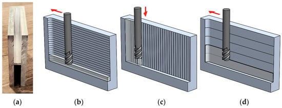
Figure 2.
(a) Machined part front view after plunge milling and finishing operations; (b) conventional strategy scheme: Vc = 160 m/min, fn = 0.14 mm/rev, ap = 3.7 mm; (c) plunge milling strategy scheme: Vc = 160 m/min, fn = 0.14 mm/rev, ae = 4.8 mm; and (d) finishing strategy scheme for both machining strategies: Vc = 160 m/min, fn = 0.07 mm/rev, ap = 14.8 mm. (Red arrows: movements).
Five machining tests were performed regarding each studied strategy (plunge or conventional contour milling), always involving two main operations: (a) produce a 140 mm length groove, 12 mm wide and 74 mm deep, followed by (b) a finishing contour milling operation of the interior walls of the groove, producing deep slots with a final width of 12.6 mm (see Figure 2a). The strategies were labeled PM (plunge) and TM (conventional). Using PM, the tool essentially acts as a drilling tool, working in the roughing process with the top face of the tool. Several holes were produced in the stock, overlapping 40% of the mill diameter (Figure 2c). This is a fast way to remove material in roughing operations, although leaving more material to be removed in the finishing operation. The TM strategy consists of removing consecutive layers along the 140 mm length of the groove, increasing its deepness in each run, layer by layer (Figure 2b). These are different approaches to opening a deep slot in the stock. The cutting speed used in both strategies was Vc = 160 m/min, corresponding to 4244 rev/min. Plunge milling (PM) was performed using fn = 0.14 mm/rev (along 74 mm of the Z-axis) and a side increment ae = 4.8 mm (40% of the tool diameter). These values were selected based on the most conservative parameters used by Bork et al. [27], Perez et al. [30], Wang et al. [37], and Ping et al. [38]. Given the effort of the milling tool in the plunge operation and the comparative nature of the present work requiring parameters as similar as possible, slightly more conservative parameters were used than those selected in the previously mentioned works. Finishing contour milling was performed using fn = 0.07 mm/rev (along 140 mm of the X-axis for each side wall of the slot) and a milling depth ap = 14.8 mm (Figure 2d). The finishing operation removed at least a side thickness of 0.3 mm, thus, the grooves ended with a final width of 12.6 mm. For comparison purposes, grooves were also produced by conventional contour milling (TM), including rough milling (Vc = 160 m/min, corresponding to 4244 rev/min, fn = 0.14 mm/rev, ap = 3.7 mm) and a finishing sequence identical to one of the plunge tests (fn = 0.07 mm/rev, ap = 14.8 mm) (Figure 2d). For both PM and TM machining operations, the cutting process was developed using a cutting lubricant (flood conditions) composed of 5% soluble oil in water. The PM strategy can be observed in Figure 2c. In addition, the climb milling cutting direction was maintained for the TM roughing and finishing operations (PM and TM) as different cutting directions tend to cause different wear and vibration levels.
The tools were fixed using an ISO40 DIN69871 cone, an ER32 H70 collet holder, and an ISO 7388-2 tie rod. The workpiece was locked in a One-Lok Single station CNC vise (Chick Workholding Solutions, Warrendale, PA, USA) with auxiliary tool steel blocks of the same height as the workpiece and with 20 mm thickness, avoiding wall vibration.
2.2.5. Roughness Analysis of the Machined Surface
At the end of each test and after finishing, the roughness was measured and recorded for later analysis using a Mahr Perthometer M1 profilometer (Mahr, Göttingen, Germany). The probe was placed in contact with the milled surface in three different regions, following the direction of each point shown in the point map in Figure 3. The probe has a cut-off value of 0.8 mm and measures a total length of 5.6 mm in seven segments. The first and last segments were ignored to allow for probe acceleration and deceleration. Surface roughness values were determined in each operating condition according to ISO 4288:1996 [39]. Figure 3 shows the points analyzed, trying to cover the start and end points of the machining process in upper and lower case, showing any differences induced by the tool length and the associated vibration. Six measurements were taken in each position; the average values were recorded and are presented in the Results section.
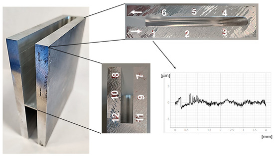
Figure 3.
Roughness measurement position on the sample surface: start of finishing position (1) and end of finishing position (6) measured at the lower and upper positions, respectively. Points from 7 to 12 represent the sample’s width-the start of the finishing position (7) and the end of the finishing position (12).
2.2.6. Tool Wear Analysis
Tool wear analysis was performed to evaluate the cutting-edge deterioration of the tools. After machining, the tools were observed by SEM (the same used to analyze the coating thickness), and the materials involved on the cutting edge were analyzed by EDS. Wear was measured using electron microscopy and ImageJ software (version 1.54f), according to the ISO 8688-2:1986 standard [40,41]. The rake and clearance faces (flank) were also analyzed.
2.2.7. Vibration Analysis
To understand the phenomena happening in the tools during the machining process, a PCB-PIEZOTRONICS (PCB Piezotronics, Depew, NY, USA) model 356A15 triaxial accelerometer was coupled to a National Instruments (National Instruments, Austin, TX, USA) model USB-4431 data acquisition card, which allowed the vibration signal developed in the X-, Y-, and Z-axes to be recorded and analyzed using LabView® software (LabVIEW NXG 5.1, January 2021) (National Instruments, Austin, TX, USA). For that, the equipment was coupled to the spindle of the CNC machining center (Figure 4). The root-mean-square (RMS) value was calculated using the vibration time signal for each test [42,43].

Figure 4.
Machining setup used for plunge and conventional milling: (a) triaxial accelerometer used to measure vibrational signal and (b) AA7050-T7451 blocks.
3. Results and Discussion
3.1. Coating Characterization
The first approach to the experimental work was performed by analyzing the coated tools. Thus, SEM and EDS analyses were performed to evaluate the coating thickness and the chemical composition.
Following the procedure previously described, the SEM images showed that the DLCSiO500W3.5O2 coating presented approximately 2 μm thickness, being homogeneous, as depicted in Figure 5a. Figure 5c–e presents the EDS spectra relative to the coating composition sampling area (Figure 5b). The EDS analyses confirmed the presence of the main expected constituents: C, W, Si, and O. In Figure 5d it can be seen that the interlayer consists of Cr. This element is used to improve the adhesion of coatings deposited by PVD, thus improving the machining properties of high-speed steel or carbide tools. W and Co appear in the EDS spectrum due to substrate interferences (WC-Co) (Figure 5a,e). The coating structure is mainly columnar. Table 5 presents the chemical composition obtained by EDS analysis. The chemical elements Ar and O come from the atmosphere created inside the reactor for the coating film deposition via PVD, as indicated in Table 4.
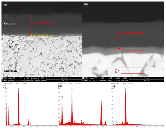
Figure 5.
SEM micrograph showing the DLCSiO500W3.5O2 film thickness deposited by PVD magnetron sputtering: (a) coating and interlayer dimensions, (b) sampling area for EDS analysis, (c) EDS spectrum from sampling area Z1, (d) EDS spectrum from sampling area Z2, and (e) EDS spectrum from sampling area Z3.
Table 5.
Chemical composition on coating and tool measured by EDS analysis.
3.2. Machining Times
In this section, the cycle time is calculated and discussed, highlighting the differences between the PM and TM strategies and the differences between the theoretical times calculated and the times provided by the CAD/CAM software used to convert the 3D model into G-code. Moreover, the machining times were also measured in real time and are equivalent to the CAD/CAM times plus the external movements of the tool for repositioning and starting a new cutting operation. In fact, the real-time measurement increased by 3% the time foreseen by the CAD/CAM software. The finishing contour operation adopted in this work was the same in the plunging and conventional tests, taking the same time. However, the machine and tool performance are not the same for both strategies because the conventional strategy leaves the slot smooth on both sides, while in plunge milling, the tool leaves more material and a wavy surface on both sides. This means that when the first side is finished, the tips of the asperities on the other side are also cut. Nevertheless, the difference in machining times depends only on the rough milling operations (plunge or conventional). The time needed to end-mill a groove with length (L), width (W), and height (H) depends on the cutting speed (Vc), i.e., the corresponding spindle rotation (n), the feed (fn), the depth of cut (ap), and the side displacement (ae) in plunge milling. If the diameter of the tool (d) almost coincides with the groove width (W), the number of runs (N) needed in each situation and the respective total machining time are determined by Equations (1)–(5):
where n represents the spindle rotation speed (rpm), Np represents the number of tool drops in plunge milling for a length L, Nc is the number of runs in finishing mode after plunging or conventional milling, tp corresponds to the time needed to rough-in plunge milling (s), and tc represents the time consumed by conventional milling (s). Table 6 shows the calculated machining times for roughing operations and the times provided by the CAD/CAM software.
n = Vc/(p · d)
np(plunging) = L/ae
nc(contour) = H/ap
tp(plunging) = np · H/(fn · n/60)
tc(contour) = nc · L/(fn · n/60)
Table 6.
Rough milling machining times.
The finishing contour operation, identical for both conventional and plunge tests, was performed in five runs with Vc = 213 m/min, a feed rate fn = 0.07 mm/rev, and a depth of cut ap = 14.8 mm, taking a machining time of 212.4 s (not relevant because the time spent is the same for both strategies). Approach and recess times, as well as tool changes and other on-air movements, must be added to the machining times to obtain the full duration of the process. However, these are relatively short times and are also identical for both strategies tested. Indeed, the difference in the calculated times and times provided by the CAD/CAM software is 10% more for CAD/CAM, which already includes the on-air movements of the tool. In sum, and regarding Table 6, for the parameters adopted, a saving of about 58.56 s was achieved by adopting the plunge method (a reduction of 20.7% in rough machining time). Thus, the productivity savings using the plunge milling strategy are evident.
It must be noted that machining time depends on the material removal ratio, which is a function of the feed rate and depth of cut parameters. Therefore, shorter times tend to create more severe wear conditions for the tool. Tool damage also depends on the cutting geometry of each situation. In these tests, conventional milling imposed stress mainly on the lateral cutting edges of the tool, while plunge milling stressed mainly the tip edges of the mill, as it works as a drill does.
3.3. Tool Wear Analysis
The productivity gains, translated by the cycle times recorded, are a huge added value in terms of companies’ competitiveness, but it is also necessary to evaluate the price to be paid in terms of tool wear and tool replacement time. For this, it is vital to analyze wear comparatively. The difference in the chip removal approach would lead to the prediction that the tools used in the plunge milling strategy should show greater wear at the end than those used in a conventional strategy, as their effort is essentially exerted along the Z (axial) axis. On the other hand, the tools used in the conventional strategy should show greater wear on the lateral cutting edges, given that their effort is mostly lateral. To confirm this assumption or not, the tools were analyzed to quantify wear and identify the differences between the wear mechanisms recorded in each case.
After the machining tests, all tools were observed on an OLYMPUS BX51M (Olympus Microscopy, Shinjuku-ku, Tokyo, Japan) optical microscope. Then, the next step was to look for similarities between the different tools used under the same conditions and the wear mechanisms to select the most representative of the five tests carried out under the same conditions. These observations were just preliminary observations, allowing a fast way of making conclusions about the tool wear. More in-depth analysis was performed using SEM equipment, as presented in the following images.
3.3.1. Analysis of the Tools Used in Plunge Milling
The first analysis relates to the tools used in the plunge milling strategy (PM). In Figure 6, two images of one of the tools used for this strategy can be seen (lateral cutting edge) emphasizing one of the cutting edges (the most representative among all the observations), (a) illustrating an overall view of the cutting edge and (b) emphasizing a detailed view of some failures to be discussed.

Figure 6.
SEM micrograph analysis of a side of the tool cutting edge used in the plunge milling strategy (PM): (a) a general overview of the lateral part of the cutting edge; (b) a detailed view of the cutting-edge tip.
Figure 6 shows a chipping of the sharp tip of the cutting edge, denoting a catastrophic failure of the tool substrate. Looking in more detail at Figure 6b, it can be seen that the adhesion of aluminum to the surface of the tool is insignificant in this part of the tool, and it is also possible to observe that there is a slight abrasion on the lateral edge of the tool as a result of contact with the material to be cut during the plunging process. However, it should also be noted that in the crater left by the chipping of the substrate, it is possible to observe a portion of adhered aluminum, thus demonstrating that the aluminum has a much greater tendency to adhere to the tool substrate (WC-Co) than to the coating used in this work. In fact, despite the tool’s higher effort made in the Z-axis, the lateral edge of the tool also contacts the part and suffers some impact and abrasion, as there is only a partial overlap of the roughing carried out on the way down and extracted by the tool in the previous roughing cycle. So, you would expect that there would be clear signs of wear on the face adjacent to the cutting edge, but this does not happen. This observation shows that the adhesion of the coating to the substrate is extremely efficient in this area of the tool, as it is not possible to observe any significant delamination of the coating, and the clearest small signs that are possible to observe relate to abrasion wear, essentially at the top of the grooves left by the grinding process of the tool substrate. However, another view of the tool cutting edge (Figure 5) shows that the coating has almost completely collapsed at the tool tip, the area of most violent contact with the material and where the main cutting effort and abrasion action occurs. In this area, the tool cuts the material, which is then forced to flow through the tool’s helical channels. However, the abrasion action in this area is extremely intense, so it would be expected that the coating would have difficulties in withstanding the actions required. Even so, it is still possible to see traces of the coating, which denotes, once again, the excellent adhesion of the coating to the substrate. Even on the substrate, it is possible to observe some circular abrasion marks (Figure 7a) corresponding to the chips’ movement that flows between the tool and the surface being cut. In Figure 7b it is possible to see the chipping effect observed in one tool tooth from another angle. The tool´s tip shows great sensitivity to chipping, denoting a lack of toughness of the tool substrate for the efforts carried out in this operation. Figure 7c shows the EDS analysis, which shows that the chemical composition of the tool surface in sample areas Z1 and Z2 is mainly composed of the W element, and in sample area Z3, the Al element can be observed from the milled surface.
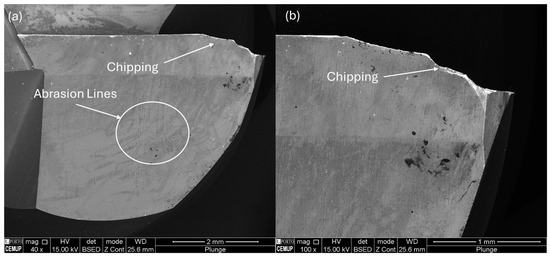
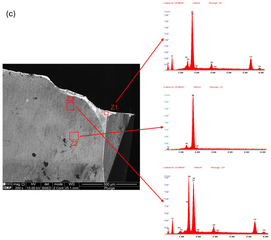
Figure 7.
SEM micrograph analysis of a tool cutting edge used in plunge milling strategy (PM): (a) top view of one of the teeth; (b) lateral view of the chipping effect in one of the three teeth; (c) EDS analysis of the tool surface.
Regarding the good performance of the coating, recent work carried out by the same group [44,45,46] has identified problems with the adhesion of some coatings (TiAlTaN, TiAlYN and TiAlTaN, TiAlYN) deposited using industrial machines on the same substrate, but machining other materials (Inconel and AMPCO alloy), a situation that was not observed in the case of these tools working according to this cutting strategy and machining an aeronautical aluminum alloy (AA7075-T7451). Thus, these coatings demonstrate good adhesion properties to the substrate and prove to be efficient in terms of hindering the adhesion of the machined material to the tool surface. The slight abrasion marks identified cannot be considered worrying, given the damage normally experienced in this type of machining operation [47], where the abrasion marks are normally much more pronounced. The same phenomena were also observed with other DLC films under other types of requirements [48]. On the other hand, the chipping of the substrate demonstrates that the grade of cemented carbide used has high hardness but inadequate toughness for the effort that was developed in this machining operation. The chipping problem was also felt by other authors [49] in the machining of superalloys for aeronautics; using a prior machining treatment of AlSi alloys to deposit a preliminary layer on the surface of the tool, this alloy melted during the first phase of machining the superalloy, filling the microcracks existing in the tool substrate and thus reducing the chipping problem. Bleicher et al. [50] attributed the chipping problems experienced in the tools to the vibration observed in the tool holder during the process.
3.3.2. Analysis of the Tools Used in Conventional Milling
The second analysis was essentially focused on the tools used to open deep slots in AA7075-T7451 alloy using a conventional strategy. As previously mentioned, machining parameters were as identical as possible to the plunge milling operation, considering that different strategies correspond to some different parameters, mainly in terms of ap and ae. The authors are also aware that the efforts of the tools are different, influencing the respective vibration levels.
Like the tools used for the plunge milling strategy, the tools used for the conventional strategy were also observed by SEM, seeking to identify a pattern of behavior that could be representative of the state in which the tools remained after machining, with emphasis on any wear mechanisms observed as well as the wear level. Figure 8 shows a typical pattern found near the cutting edge of the tool.
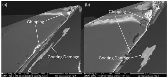
Figure 8.
Side view of SEM micrograph analysis of a tool cutting edge used in conventional milling strategy (TM): (a) general overview of a cutting edge; (b) detailed view of the cutting edge.
As can be concluded from the observation in Figure 8a, the level of wear presented by these tools is more significant, also presenting some wear phenomena not so evident in the tools used for the plunge milling strategy. In addition to the chipping also observed in the previously analyzed tools, there are evident signs of abrasion, which caused the coating to detach in some areas. In addition to the chipping previously observed at the sharp end of the cutting edge, there are also some evidences of chipping already outside the sharp edge of the tool, which corroborates the idea previously developed that the grade of cemented carbide used in the manufacture of the tools is not the most appropriate, a situation that will have to be reviewed in future work. Tools revealed a very low level of adhesion to the AA7050-T7451 alloy, and this is more evident in the chipping area, where the tool material is in direct contact with the material of the part being machined. As already mentioned, the selected coating provides low adhesion of the machined material; thus, taking this objective into account, it can be stated that the selection of an efficient coating was successfully achieved. Regarding abrasion resistance, the situation appears a little different.
Figure 9 depicts SEM micrographs showing a top view (Figure 9a) and a lateral view (Figure 9b) of a tooth of one of the mills used for the conventional strategy, revealing that the wear intensity is not too different from the one reported using the plunge milling strategy, although a little more severe. Figure 9c shows the EDS analysis, which shows that the chemical composition of the tool surface in sample areas Z1 and Z2 consists mainly of the W element, and in sample area Z3, the Al element can be observed from the milled surface.
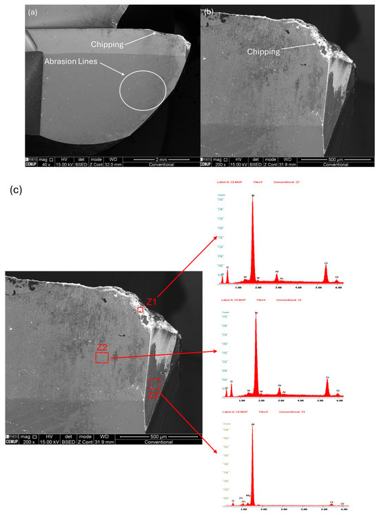
Figure 9.
SEM micrograph analysis of a tool cutting edge used in the conventional milling strategy (TM): (a) top view of one of the teeth; (b) lateral view of the chipping effect in one of the three teeth; (c) EDS analysis of the tool surface.
Given the short period the tools were subjected to, the level of wear obtained is quite high. The cutting conditions used were a little conservative, given the literature [27,30,37,38], but even under these conditions, the wear is significant, mainly the chipping effect. The main factors behind this phenomenon are the grain size of the cemented carbide used as well as the demanding cutting parameters used.
The difference observed in the cases analyzed is directly related to the effort made by the tool in the cutting process and, mainly, to the chip flow. If the flow of the chips affects particularly a small area of the tool’s cutting edge, the cutting stresses may be greater than the adhesion strength of the coating to the substrate. Therefore, in these areas of greater stress intensity and constant flow of the chips, the adhesion of the coating to the substrate, despite being sufficient in the case of the plunge milling strategy, does not seem to be the most suitable for the conventional milling strategy. This fact leaves doubts regarding the effectiveness of the parameters used in the coating deposition. However, according to the observations made in Figure 6, the adhesion of the coating to the substrate seemed to be perfectly sufficient for the efforts made in the machining process. This highlights the fact that the plunge milling strategy initially seems more demanding for the tool, but this is not confirmed in practice. The substrate shows a slightly greater degradation in the case of conventional milling compared with plunge milling, and the coating also shows greater signs of deterioration, with more wear mechanisms being observed in conventional milling that were not present when the plunge milling strategy was used.
From this observation, some conclusions can immediately be drawn: (a) the efforts developed in conventional milling are more severe for the substrate and the coating of the tools; (b) the grade of cemented carbide has to be carefully chosen, as if it does not present the required toughness levels, it will lead to catastrophic failure of the tool’s sharp edges; (c) in the case of plunge milling, the coating does not compromise the overall behavior of the tool, as the fracture occurs mainly through the substrate; (d) the coating that seems perfectly suited to the plunge milling strategy seems less suitable for the conventional milling strategy; (e) the effect of reducing the adhesion of the machined material to the tool is perfectly achieved with the aid of the coating, which worked almost perfectly in this aspect; (f) the adhesion strength of the coating to the substrate and its abrasion resistance can be improved further by improving the deposition parameters. Gao et al. [51] attributed the catastrophic failure of cemented carbide tools in the machining of bonded steels to the formation of Co binder phases with hexagonal closest-packed structures, which induced the formation of segregations and impurities. Also, the thermal cycles are pointed out as one of the main factors for the rapid failure of WC-Co substrates. Fernandes et al. [52] also reported problems with a detachment of DLC coatings when machining aluminum alloys of the AA6351-T6 type, as well as adhesion of the machined material to the coating (an effect felt very mildly in this work) and deformation and flank wear. Hovsepian et al. [53] advocate the use of tools coated with TiAlN/VN in the machining of aluminum alloys for aeronautics, noting that tools equipped with this coating have performance very similar to tools coated with DLC.
It is also clear that this study opens an opportunity to investigate the differences between the wear mechanisms observed depending on each machining strategy adopted, with the clear idea that the study of wear according to a given strategy is only part of a study. A deeper knowledge of the behavior of tools and coatings is necessary for each specific machining strategy, and not just for each material to be machined.
3.4. Surface Roughness Analysis
Although the finishing operation was excluded from the productivity study, this operation is extremely important to provide the machined surfaces with the quality normally required. Although the finishing milling time is the same, the conditions in which the surface is found before this operation are not the same: while the conventional milling strategy leaves slight horizontal grooves in relation to the work plane, the plunge milling leaves vertical grooves that are more pronounced the higher the side displacement is. Therefore, the greater the overlap, the higher the volume of material to be removed in finishing operations, but this fact collides with the desired productivity, which will be lower the lower the side displacement is. This fact, combined with the need to use a very long tool, as the depth of the slot is relatively large compared with the most common needs, tends to induce higher vibrations in the tool, which translates into greater roughness on the machined surface. This behavior has already been reported by other authors [54,55,56]. The high length of the cutter will also certainly induce different finishing qualities at the top of the slot (closer to the spindle) and lower quality at the end of the tool, that is, at the bottom of the slot. On the other hand, to optimize the path, the tool travels along one wall of the slot and then travels along the opposite wall, avoiding wasted time. This fact means that a concordant or discordant machining strategy is always adopted, depending on the direction considered for the movement of the part relative to the mill axis.
This introduction served to contextualize the need to evaluate surface roughness after finishing in several locations, at the top and bottom of each slot and on the right and left wall of the slot, for each machining strategy. While measuring at the top and bottom essentially corroborates the pre-defined idea that the tool will vibrate less next to the spindle, measurements at the left and right walls of the slot essentially compare surfaces produced at the start and at the end of the finishing operations. Thus, to better define the measurement locations, the roughness at the beginning of the finishing operation is defined as “Start of finishing” and the opposite part as “End of finishing”. The Ra and Rz results are presented in Table 7 and Table 8.
Table 7.
Surface roughness measurements (Ra) after finishing operation.
Table 8.
Surface roughness measurements (Rz) after finishing operation.
Through the results shown in Table 7 and Table 8, it is possible to verify that the high length of the cutter is felt in the surface roughness after finishing on the slot surface and that the roughness values, in addition to being higher in the lower part than in the upper part, are also slightly higher in the surface finish resulting from the plunge-milling roughing strategy than that from the conventional strategy. This is corroborated by the vibration analysis presented below, in which there is a period of greater vibration during the finishing of the first wall and then a reduction in the vibration intensity on the second wall. This fact occurs only in samples in which the roughing was carried out by plunge milling, because this strategy leaves excess material on both walls, and when the finishing operation is carried out on the first wall, there is interference between the tool and the excess material in the opposite wall. When finishing the second wall, there is no longer any material that could interfere with the tool on the first wall, as this has already been finished. This does not occur when roughing is made by conventional milling. The roughness values after finishing are quite similar, with a very slight increase in the second wall to be finished, which is not relevant.
If the slot had a greater width, the use of a tool with a larger diameter would be advisable, reducing the height/diameter ratio, which would increase the stiffness of the tool and reduce this effect (higher roughness in the bottom of the slot).
3.5. Vibration Analysis
Figure 10 shows the vibrational signal captured during the plunge-milling process of the AA7050-T7451 block. In this analysis, it must be noted that, in comparison to Figure 2b, the Y- and Z-axes were swapped due to the hardware configuration. Figure 2a is valid only for CAD/CAM purposes. The X- and Z-axes present signals from the tool height and the CNC table movement captured by the triaxial accelerometer, respectively, and the Y-axis is sensitive to tool movement in relation to the table. Each peak represents the tool entry into the aluminum stock. At the beginning of the plunge-milling process, a change in the vibrational signal in the Z-axes and Y-axes is noticed in the middle of the second entry, suggesting that a first small tool failure had occurred. In the first phase, the vibrational signal in the Y-axis increases, and in the Z-axis the signal pattern remains. At the beginning of the second phase, it is assumed that the tool suffered another failure pointed out by another change in the vibration signal, as it stays high in the Y-axis and decreases in the Z-axis. At the end of the milling process, close to the bottom of the pocket, a new change in the vibrational pattern is observed, an increase in the vibration signal of the X- and Z-axes. According to Montassar et al. [53], the larger the tool radius, the greater the amount of material remaining to be re-machined. At the bottom of the pocket, the tool cuts out a small amount of material that was previously left over. They noted that the remaining material generates forces at the rear of the tool due to the springback and the machining of the material left at the tip of the tool, generating an increase in the vibration signal captured during the machining process. In this test, it is possible to observe the same phenomenon observed by Montassar et al. [57].
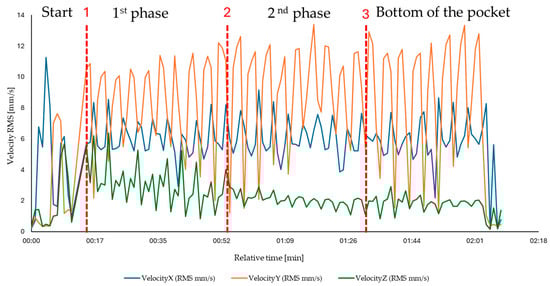
Figure 10.
Vibrational analysis of the plunge-milling roughing process (Blue line: X velocity (RMS [mm/s]); Yellow line: Y velocity (RMS [mm/s]); Green line: Z velocity (RMS [mm/s])).
Figure 11a shows the vibratory signal of the finishing process, which starts on the right side of the previous machined wall and ends on the left side, and Figure 11b shows the toolwork in the finishing operation after the plunge-milling roughing operation. Different behavior of the vibrational signals is observed during the five stages of the milling process. In the first stage, it is observed that there is a pair of vibrational signals; the most intense refers to the right side of the wall, and the one with lower intensity refers to the left side. Considering that the diameter of the tool is 12 mm and that the slot width is the same as the tool diameter, when the tool starts the finishing process, cutting a side width of 0.3 mm on the right side, the residual material is entirely removed and the remaining material on the left side is partially removed. However, when the tool passes on the left side of the block, there is a smaller amount of material to be removed (just on the left), which results in a lower vibration level, corresponding to a decrease in the vibration signal presented in the first machining stage. Hence, the vibration level is different when finishing the right and left sides of the slot, because in the first side, there is interference of the opposite, while in the second this interference does not occur because the right side is already finished. This situation is valid only for the finishing operation.

Figure 11.
(a) Vibrational analysis of the plunge-milling finishing process (Blue line: X velocity (RMS [mm/s]); Yellow line: Y velocity (RMS [mm/s]); Green line: Z velocity (RMS [mm/s])); (b) Finishing milling scheme: front view.
In the following stages, indicated by vibrational signal sets 2, 3, and 4, a decay in the vibration signal on both the right and left sides is observed, but in the final stage, indicated by vibrational set 5, the vibrational intensity of both sides is reduced and becomes equal, indicating that smoothness of the machined surface has been achieved. This behavior is according to the observations made by Geng et al. [58]. They observed that tool vibration increases when there is an increase in residual material along the feed direction, which also increases the cutting force. When the residual material is exhausted, the tool vibration and cutting forces also decrease.
Figure 12 shows the vibration signal recorded during conventional milling of the AA7050-T7451 stock. The X- and Z- axes represent signals from the CNC table movements, and the Y-axis is sensitive to the tool movements captured by the triaxial accelerometer. Figure 7a shows the vibration signal from the roughing process. In the first 2 minutes, two events marked by intense peaks were observed (marked by *), one at 20 s and the other at 60 s, indicating the occurrence of a small failure in the tool teeth, as the vibration intensity remains the same. At a time of 173 s, a more intense flaw occurs, as the vibration intensity decreases until the end of the machining process.
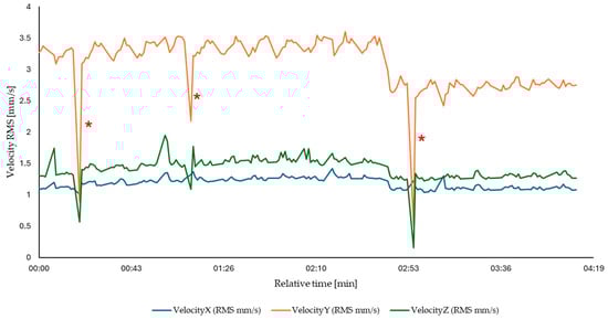
Figure 12.
Vibrational analysis of the conventional roughing process (Blue line: X velocity (RMS [mm/s]); Yellow line: Y velocity (RMS [mm/s]); Green line: Z velocity (RMS [mm/s])).
The average RMS vibration measured in the three directions, X, Y, and Z, was determined according to Equation (6) [59]:
When comparing the average RMS of the three milling processes, it can be seen that the plunge-milling process has an average RMS value that is 63.86% higher (9.99 mm/s) than the conventional milling process (3.61 mm/s) due to the intense vibration that occurs when the tool comes into contact with the material and plunges into it. The finishing process has the lowest average RMS value of 0.49 mm/s; due to its nature, it removes little material left over from the milling processes.
4. Conclusions
This work aimed to comparatively study two machining strategies, analyzing several aspects: productivity, tool wear, the interrelationship between wear and vibrations recorded during machining, and the surface roughness of the workpieces. It should be noted that competitive advantages in terms of productivity could be nullified by more severe tool wear, a situation that had not been addressed in any other study to date and constituted a gap in the literature. After the data collection and corresponding analysis, it was possible to draw some conclusions that show that it is more advantageous to opt for the plunge milling strategy:
- The roughing operation carried out by plunge milling saves about 20.7% of the time needed to carry out the same work using conventional milling. Therefore, there are significant productivity gains by opting for the plunge milling strategy.
- The wear seen on tools using the plunge milling strategy is slightly lower than that seen on tools used in the conventional milling strategy.
- The tools invariably presented chipping wear and abrasive lines as the main phenomenon. This fact must be closely linked to the grade of cemented carbide used as a substrate in the tools.
- The DLCSiO500W3.5O2 coating contributed to less tool wear in the machining process as well as less adhesion of the material to be machined to the tool. This translates into a lower level of roughness, as the adhesion of the machined material to the tool normally leads to lower surface roughness.
- There is a clear relationship between the tool failure and the vibration level observed in the spindle of the CNC equipment. It was possible to correlate the tendency for a slight increase in vibration during the tests, as the wear on the tool became more severe. The chipping phenomenon was also felt, as the failure of one end of a blade was felt as a vibration peak and an increase in the overall level of vibration because of the imbalance between the different cutting edges.
- Analyzing the average RMS of the two milling processes, it can be seen that the best strategy is the conventional milling process (3.61 mm/s), which has a lower vibration level than the plunge process, preserving the useful life of the equipment long-term.
- Surface roughness is affected by the tool length and wear, being lower at the top of the slot (lower vibration of the tool) and at the beginning of the finishing process. The differences are not significant, but it seems impossible to ensure the same roughness in the hole slot surface whenever using plunge or traditional milling strategies.
In sum, it can be stated that the plunge milling strategy presents greater productivity, slightly lower wear levels, slightly worse surface roughness indices, and higher vibration levels, mainly in the finishing operation but not in the roughing operation. Therefore, it is possible to conclude that the plunge milling strategy presents competitive advantages in terms of productivity in general because less time is consumed compared with conventional milling. This machining strategy can be particularly useful in all situations where it is necessary to open more or less deep and lengthy slots, mainly when they generate thin support walls, where the tangential forces developed by the tool are high enough to increase the vibration phenomena, and the vertical action of the tool in the plunge milling strategy exerts a more pronounced load only on the base of the workpiece, which is supported on the machining center table. In addition to the novel and broad way in which this study was developed, it is urgent to raise industry awareness of the advantages of applying this machining strategy. The fact that the tools operate vertically (drill-type) certainly rules out the wider application of this strategy, which is already well-rooted in CAD/CAM software, but it is still little used in practice due to a lack of knowledge about the vibration levels and tool wear developed. As there are numerous situations in which this strategy could be decisive in saving economic and environmental resources (fewer tools consumed), it is up to the industry to more consistently use geometries where this strategy is suitable, such as the one shown in this work. Industries such as the aeronautical, aerospace, and defense industry, as well as more common industries such as industrial equipment manufacturing, should take more significant steps in adopting this strategy, taking advantage of the benefits highlighted by this work.
Further studies will be necessary to improve the behavior of the tool substrate, using other, finer grades of cemented carbide and with different percentages of Co, and the coating deposition parameters can also be optimized, although they are already at a good stage of maturity. The main limitation of the study is the focus on a certain set of machining parameters, which should be expanded and studied in more depth using other ranges of parameters.
Author Contributions
Conceptualization, F.J.G.S. and R.C.M.S.-C.; methodology, L.L.M. and R.P.M.; validation, F.F., L.M.D. and R.C.B.C.; formal analysis, F.F., L.M.D. and R.C.B.C.; investigation, R.C.M.S.-C. and V.F.C.S.; resources, F.J.G.S.; data curation, L.L.M., F.F., L.M.D. and R.C.B.C.; writing—original draft preparation, F.J.G.S., L.L.M., R.P.M. and R.C.M.S.-C.; writing—review and editing, V.F.C.S.; visualization, V.F.C.S., R.C.B.C., L.M.D. and R.P.M.; supervision, F.J.G.S.; project administration, F.J.G.S.; funding acquisition, F.J.G.S. All authors have read and agreed to the published version of the manuscript.
Funding
The work was developed under the “DRIVOLUTION—Transition to the factory of the future”, with the reference DRIVOLUTION C644913740-00000022 research project, supported by European Structural and Investments Funds with the “Portugal2020” program scope.
Data Availability Statement
The data available are provided in this article.
Acknowledgments
The authors thank ISEP, INEGI, and FEUP for their institutional support. The authors also acknowledge Rui Rocha from CEMUP Lab, due to his contribution to the SEM analyses and interpretation, and Ricardo Alexandre from INOVATOOLS company, due to his availability to provide the tools used in this work free of charge, as well as Victor Moreira, due to his collaboration in the machining tests. Filipe Fernandes acknowledges the UIDB/00285/2020 and LA/P/0112/2020 projects, sponsored by FEDER Funds through Portugal 2020 (PT2020), the Competitiveness and Internationalization Operational Program (COMPETE 2020), and national funds through the Portuguese Foundation for Science and Technology (FCT).
Conflicts of Interest
The authors declare no conflicts of interest.
References
- Iglesias, I.; Sanchez, A.; Silva, F.J.G. Robotic path compensation training method for optimizing face milling operations based on non-contact CMM techniques. Robot. Comput.-Integr. Manuf. 2024, 85, 102623. [Google Scholar] [CrossRef]
- Küpper, U.; Seelbach, T.; Heidemanns, L.; Prinz, S.; Herrig, T.; Bergs, T. Effects of the Manufacturing Chain on the Surface Integrity when Machining Fir Tree Slots with Alternative Manufacturing Processes. Procedia CIRP 2022, 108, 728–733. [Google Scholar] [CrossRef]
- Klocke, F.; Seimann, M.; Binder, M.; Doebbeler, B. Milling of Fir-Tree Slots in Allvac 718 plus. Procedia CIRP 2018, 77, 409–412. [Google Scholar] [CrossRef]
- Jiaa, Y.; Chia, G.; Lia, W.; Wanga, Z.; Cuia, L. Influence of Wear Pattern of Graphite Electrode on EDM Geometric Accuracy of Slot Machining. Procedia CIRP 2020, 95, 408–413. [Google Scholar] [CrossRef]
- Maradia, U.; Kliuev, M.; Baumgart, C. Efficient machining of complex-shaped seal slots for turbomachinery. CIRP Ann.—Manuf. Technol. 2018, 67, 209–212. [Google Scholar] [CrossRef]
- Li, M.; Chen, Y.; Tan, M.; Yang, X.; Xiao, Z. Surface integrity and acoustic emission characteristics during slot milling 3D carbon/carbon composites using superabrasive diamond grinding point. Diam. Relat. Mater. 2023, 137, 110166. [Google Scholar] [CrossRef]
- Silva, F.J.G.; Gouveia, R.M. Cleaner Production—Toward a Better Future; Springer: Cham, Switzerland, 2020; ISBN 978-3030231644. [Google Scholar]
- Muaz, M.; Choudhury, S.K. Experimental investigations and multi-objective optimization of MQL-assisted milling process for finishing of AISI 4340 steel. Measurement 2019, 138, 557–569. [Google Scholar] [CrossRef]
- Rodriguez-Alabanda, O.; Guerrero-Vaca, G.; Molero, E.; Romero, P.E. Experimental analysis of deep slot milling in EN AW 2024-T3 alloy by stretched trochoidal toolpath and variable helix angle tool. CIRP J. Manuf. Sci. Technol. 2021, 35, 346–360. [Google Scholar] [CrossRef]
- Li, Z.; Hu, P.; Xie, F.; Tang, K. A variable-depth multi-layer five-axis trochoidal milling method for machining deep freeform 3D slots. Robot. Comput.-Integr. Manuf. 2021, 68, 102093. [Google Scholar] [CrossRef]
- Niknam, S.A.; Songmene, V. Analysis of friction and burr formation in slot milling. Procedia CIRP 2014, 17, 755–759. [Google Scholar] [CrossRef]
- Vogtel, P.; Klocke, F.; Lung, D. High Performance Machining of Profiled Slots in Nickel-Based-Superalloys. Procedia CIRP 2014, 14, 54–59. [Google Scholar] [CrossRef]
- Jaeger, E.; Bergmann, J.A.; Wiederkehr, P. Simulation-based analysis for the machining of thin-walled, additively manufactured support structures. Procedia CIRP 2023, 118, 454–458. [Google Scholar] [CrossRef]
- Gueli, M.; Ma, J.; Cococcetta, N.; Pearl, D.; Jahan, M.P. Experimental investigation into tool wear, cutting forces, and resulting surface finish during dry and flood coolant slot milling of Inconel 718. Procedia Manuf. 2021, 53, 236–245. [Google Scholar] [CrossRef]
- Bagherzadeh, A.; Kuram, E.; Budak, E. Experimental evaluation of eco-friendly hybrid cooling methods inslot milling of titanium alloy. J. Clean. Prod. 2021, 289, 125817. [Google Scholar] [CrossRef]
- Osman, K.A.; Yılmaz, V.; Ünver, H.O.; Seker, U.; Kılıç, S.E. Slot milling of titanium alloy with hexagonal boron nitride and minimum quantity lubrication and multi-objective process optimization for energy efficiency. J. Clean. Prod. 2020, 258, 120739. [Google Scholar] [CrossRef]
- Pleta, A.; Niaki, F.A.; Mears, L. A comparative study on cutting forces coefficient identification between trochoidal and slot milling. Procedia Manuf. 2018, 26, 570–579. [Google Scholar] [CrossRef]
- Dodok, T.; Čuboňová, N.; Císara, M.; Kurica, I.; Zajačkoa, I. Utilization of strategies to generate and optimize machining sequences in CAD/CAM. Procedia Eng. 2017, 192, 113–118. [Google Scholar] [CrossRef]
- Vila, C.; Abellán-Nebota, J.V.; Siller-Carrillo, H.R. Study of different cutting strategies for sustainable machining of hardened steels. Procedia Eng. 2015, 132, 1120–1127. [Google Scholar] [CrossRef]
- Gaur, M.; Law, M. Pocket milling strategies using combined-mode and feed-direction dependent stability criteria. Procedia CIRP 2019, 82, 261–266. [Google Scholar] [CrossRef]
- Pal, P.; Tigga, A.M.; Kumar, A. A strategy for machining interacting features using spatial reasoning. Int. J. Mach. Tools Manuf. 2005, 45, 269–278. [Google Scholar] [CrossRef]
- Zhang, H.; Wang, W.; Zhang, S.; Zhang, Y.; Zhou, J.; Wang, Z.; Huang, B.; Huang, R. A novel method based on deep reinforcement learning for machining process route planning. Robot. Comput.-Integr. Manuf. 2024, 86, 102688. [Google Scholar] [CrossRef]
- Wang, Z.; Zhang, S.; Zhang, H.; Wang, W.; Zhang, Y.; Liang, J.; Huang, R.; Huang, B. Machining feature process route planning based on a graph convolutional neural network. Adv. Eng. Inform. 2024, 59, 102249. [Google Scholar] [CrossRef]
- Guo, L.; Yang, W.; Sun, J. A continuous oscillating milling strategy based on uniform wear theory for improving the service life of the ball-end cutter. Tribol. Int. 2024, 192, 109318. [Google Scholar] [CrossRef]
- Wagih, M.; Maher, I.; El-Hofy, H.; Yan, J.; Hassan, M.A. Analysis and development of elliptical tool path in trochoidal milling. CIRP J. Manuf. Sci. Technol. 2023, 47, 168–183. [Google Scholar] [CrossRef]
- Duan, Z.; Li, C.; Zhang, Y.; Dong, L.; Bai, X.; Yang, M.; Jia, D.; Li, R.; Cao, H.; Xu, X. Milling surface roughness for 7050 aluminum alloy cavity nfluenced by nozzle position of nano fluid minimum quantity lubrication. Chin. J. Aeronaut. 2021, 34, 33–53. [Google Scholar] [CrossRef]
- Bork, C.A.S.; Gonçalves, J.F.S.; Gomes, J.O.; Gheller, J. Performance of the jatropha vegetable-base soluble cutting oil as a renewable source in the aluminum alloy 7050-T7451 milling. CIRP J. Manuf. Sci. Technol. 2014, 7, 210–221. [Google Scholar] [CrossRef]
- Wang, B.; Liu, Z. Acoustic emission signal analysis during chip formation process in high-speed machining of 7050-T7451 aluminum alloy and Inconel 718 superalloy. J. Manuf. Process. 2017, 27, 114–125. [Google Scholar] [CrossRef]
- Ping, Z.; Yue, X.; Shuangfeng, H.; Ailing, S.; Baoshun, L.; Xiao, Y. Experiment and simulation on the high-speed milling mechanism of aluminum alloy 7050-T7451. Vacuum 2020, 182, 109778. [Google Scholar] [CrossRef]
- Perez, I.; Madariaga, A.; Cuesta, M.; Garay, A.; Arrazola, P.J.; Ruiz, J.J.; Rubio, F.J.; Sanchez, R. Effect of cutting speed on the surface integrity of face milled 7050-T7451 aluminium workpieces. Procedia CIRP 2018, 71, 460–465. [Google Scholar] [CrossRef]
- Chang, H.; Li, L.; Shi, R. Design and manufacturing technology of high-speed milling cutter for aluminum alloy. Procedia Eng. 2017, 174, 630–637. [Google Scholar] [CrossRef]
- Berry, L.; Wheatley, G.; Ma, W.; Nejad, R.M.; Berto, F. The influence of milling induced residual stress on fatigue life of aluminum alloys. Forces Mech. 2022, 7, 100096. [Google Scholar] [CrossRef]
- Kechagias, J. Multiparameter signal-to-noise ratio optimization for end milling cutting conditions of aluminium alloy 5083. Int. J. Adv. Manuf. Technol. 2024, 132, 4979–4988. [Google Scholar] [CrossRef]
- Fountas, N.A.; Stergiou, C.I.; Vaxevanidis, N.M. Programmable Support Functions to Assist Process Planning for Aeronautical Parts Manufacturing. In Proceedings of the ASME 2014 12th Biennial Conference on Engineering Systems Design and Analysis, Copenhagen, Denmark, 25–27 June 2014; Volume 1. Applied Mechanics; Automotive Systems; Biomedical Biotechnology Engineering; Computational Mechanics; Design; Digital Manufacturing; Education; Marine and Aerospace Applications. [Google Scholar] [CrossRef]
- Fan, W.; Zheng, L.; Ji, W.; Xu, X.; Wang, L.; Lu, Y.; Zhao, X. Function block-based closed-loop adaptive machining for assembly interfaces of large-scale aircraft components. Robot. Comput.-Integr. Manuf. 2020, 66, 101994. [Google Scholar] [CrossRef]
- Scott, C.T.; Daily, M. The development of a microcomputer CAD/CAM and decision support system for the manufacturing of aerospace vehicles. Comput. Ind. Eng. 1988, 15, 14–23. [Google Scholar] [CrossRef]
- Zhang, P.; Zhang, S.; Zhang, J.; Sun, Y.; Zhou, H.; Yue, X. Influence of milling parameters on the microstructural evolution mechanism of 7075-T6 aluminum alloy. Vacuum 2024, 222, 113100. [Google Scholar] [CrossRef]
- Ping, Z.; Xiujie, Y.; Penghao, W.; Xiao, Y. Surface integrity and tool wear mechanism of 7050-T7451 aluminum alloy under dry cutting. Vacuum 2021, 184, 109886. [Google Scholar] [CrossRef]
- ISO 4288:1996; Geometrical Product Specifications (GPS)—Surface Texture: Profile Method—Rules and Procedures for the Assessment of Surface Texture. International Organization for Standardization: Geneva, Switzerland, 1996.
- ISO 8688-2; Tool life testing in milling—Part 2: End milling. International Organization for Standardization: Geneva, Switzerland, 1989.
- Martinho, R.P.; Silva, F.J.G.; Baptista, A.P.M. Cutting forces and wear analysis of Si3N4 diamond coated tools in high speed machining. Vacuum 2008, 82, 1415–1420. [Google Scholar] [CrossRef]
- Daniyan, I.A.; Tlhabadira, I.; Daramola, O.O.; Mpofu, K. Design and Optimization of Machining Parameters for Effective AISI P20 Removal Rate during Milling Operation. Procedia CIRP 2019, 84, 861–867. [Google Scholar] [CrossRef]
- Martinho, R.P.; Silva, F.J.G.; Martins, C.; Lopes, H. Comparative study of PVD and CVD cutting tools performance in milling of duplex stainless steel. Int. J. Adv. Manuf. Technol. 2019, 102, 2423–2439. [Google Scholar] [CrossRef]
- Silva, F.J.G.; Sebbe, N.P.V.; Costa, R.D.F.S.; Pedroso, A.F.V.; Sales-Contini, R.C.N.; Barbosa, M.L.S.; Martinho, R.P.M. Investigations on the Surface Integrity and Wear Mechanisms of TiAlYN-Coated Tools in Inconel 718 Milling Operations. Materials 2024, 17, 443. [Google Scholar] [CrossRef]
- Nogueira, F.R.; Pedroso, A.F.V.; Silva, F.J.G.; Campilho, R.D.S.G.; Sales-Contini, R.C.M.; Sebbe, N.P.V.; Casais, R.C.B. A Comparative Study on the Wear Mechanisms of Uncoated and TiAlTaN-Coated Tools Used in Machining AMPCO® Alloy. Coatings 2024, 14, 4. [Google Scholar] [CrossRef]
- Sebbe, N.P.V.; Fernandes, F.; Silva, F.J.G.; Pedroso, A.F.V.; Sales-Contini, R.C.S.; Barbosa, M.L.S.; Durão, L.M.; Magalhães, L.L. Wear behavior of TiAlVN coated tools in milling operations of INCONEL 718. Coatings 2024, 14, 311. [Google Scholar] [CrossRef]
- Sousa, V.F.C.; Silva, F.J.G.; Alexandre, R.; Pinto, G.; Baptista, A.; Fecheira, J.S. Investigations on the Wear Performance of Coated Tools in Machining UNS S32101 Duplex Stainless Steel. Metals 2022, 12, 896. [Google Scholar] [CrossRef]
- Silva, F.J.G.; Martinho, R.P.; Baptista, A.P.M. Characterization of laboratory and industrial CrN/CrCN/diamond-like carbon coatings. Thin Solid Film. 2014, 550, 278–284. [Google Scholar] [CrossRef]
- Aramesh, M.; Montazeri, S.; Veldhuis, S.C. A novel treatment for cutting tools for reducing the chipping and improving tool life during machining of Inconel 718. Wear 2018, 414–415, 79–88. [Google Scholar] [CrossRef]
- Bleicher, F.; Ramsauer, C.M.; Oswald, R.; Leder, N.; Schoerghofer, P. Method for determining edge chipping in milling based on tool holder vibration measurements. CIRP Ann. 2020, 69, 101–104. [Google Scholar] [CrossRef]
- Gao, S.; Zheng, M.; Zhu, J.; Chen, J. Mechanism of adhesion failure during interrupted cutting with cemented carbide tools: Experimental and ab-initio perspective. Int. J. Refract. Met. Hard Mater. 2021, 98, 105549. [Google Scholar] [CrossRef]
- Fernandes, G.H.N.; Lopes, G.H.F.; Barbosa, L.M.Q.; Martins, P.S.; Machado, Á.R. Wear mechanisms of diamond-like carbon coated tools in tapping of AA6351 T6 aluminium alloy. Procedia Manuf. 2021, 53, 293–298. [Google Scholar] [CrossRef]
- Hovsepian, P.E.; Luo, Q.; Robinson, G.; Pittman, M.; Howarth, M.; Doerwald, D.; Tietema, R.; Sim, W.M.; Deeming, A.; Zeus, T. Surface and Coatings Technology TiAlN/VN superlattice structured PVD coatings: A new alternative in machining of aluminium alloys for aerospace and automotive components. Surf. Coat. Technol. 2016, 201, 265–272. [Google Scholar] [CrossRef]
- Abebe, R.; Gopal, M. Exploring the effects of vibration on surface roughness during CNC face milling on aluminum 6061-T6 using sound chatter. Mater. Proc. 2023, 90, 43–49. [Google Scholar] [CrossRef]
- Swan, R.; Penney, J.; Corson, G.; Nazario, J.; Schmitz, T. Surface location error in robotic milling: Effect of combined low frequency and high frequency vibration modes. CIRP J. Manuf. Sci. Technol. 2024, 49, 203–215. [Google Scholar] [CrossRef]
- Toh, C.K. Vibration analysis in high speed rough and finish milling hardened steel. J. Sound Vib. 2004, 278, 101–115. [Google Scholar] [CrossRef]
- Montassar, F.; Frédéric, M.; Johanna, S.; Walter, R. Cutting parameters and tool geometry selection for plunge milling—Analysis of cutting forces at the bottom of deep titanium workpieces. J. Manuf. Process. 2021, 62, 491–500. [Google Scholar] [CrossRef]
- Geng, D.; Sun, Z.; Liu, Y.; Liu, L.; Ying, E.; Cai, J.; Jiang, X.; Zhang, D. Unravelling the influence of vibration on material removal and microstructure evolution in ultrasonic transversal vibration-assisted helical milling of Ti-6Al-4V holes. J. Mater. Process. Technol. 2024, 326, 118320. [Google Scholar] [CrossRef]
- Chibane, H.; Morandeau, A.; Serra, R.; Bouchou, A.; Leroy, R. Optimal milling conditions for carbon/epoxy composite material using damage and vibration analysis. Int. J. Adv. Manuf. Technol. 2013, 68, 1111–1121. [Google Scholar] [CrossRef]
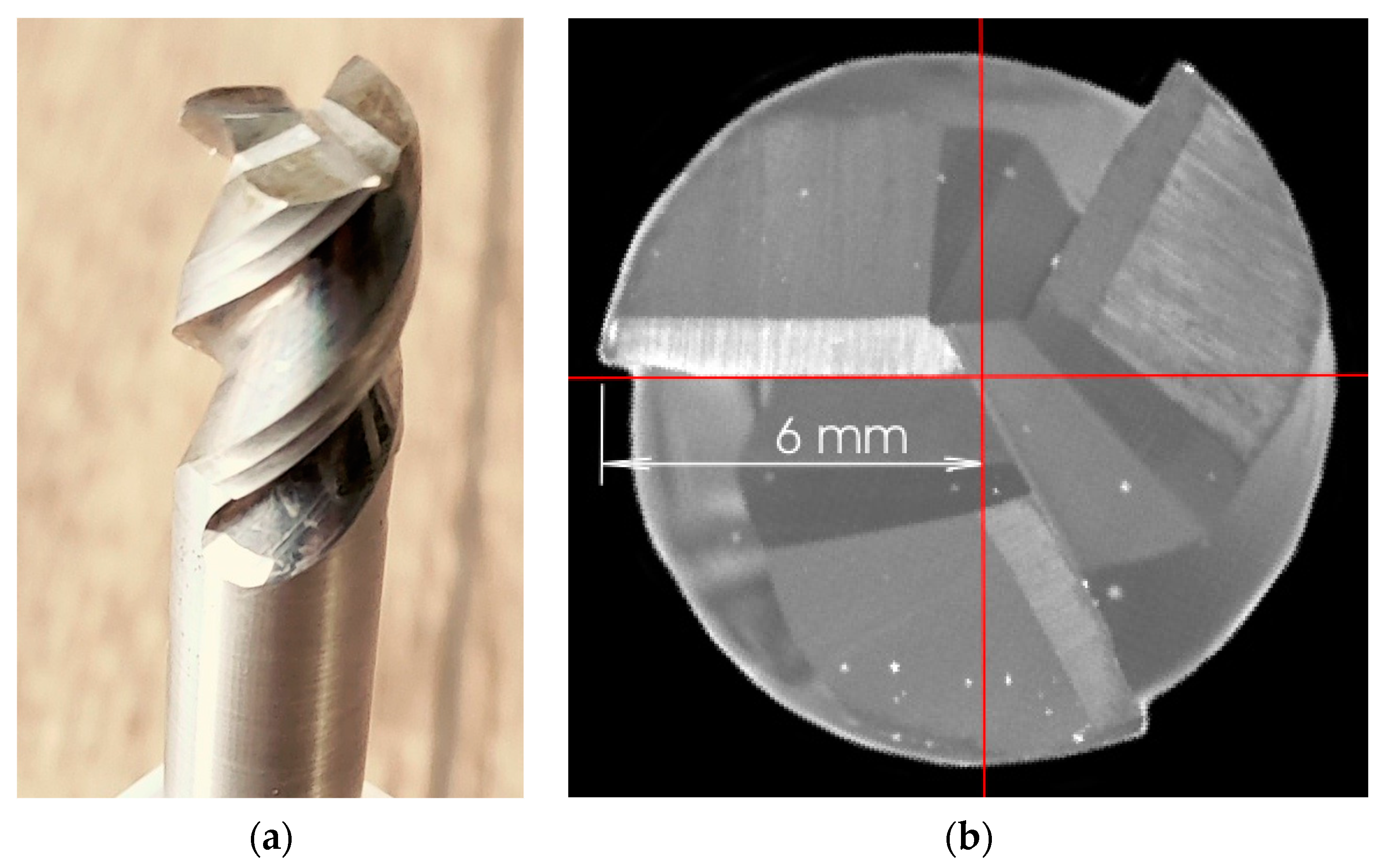
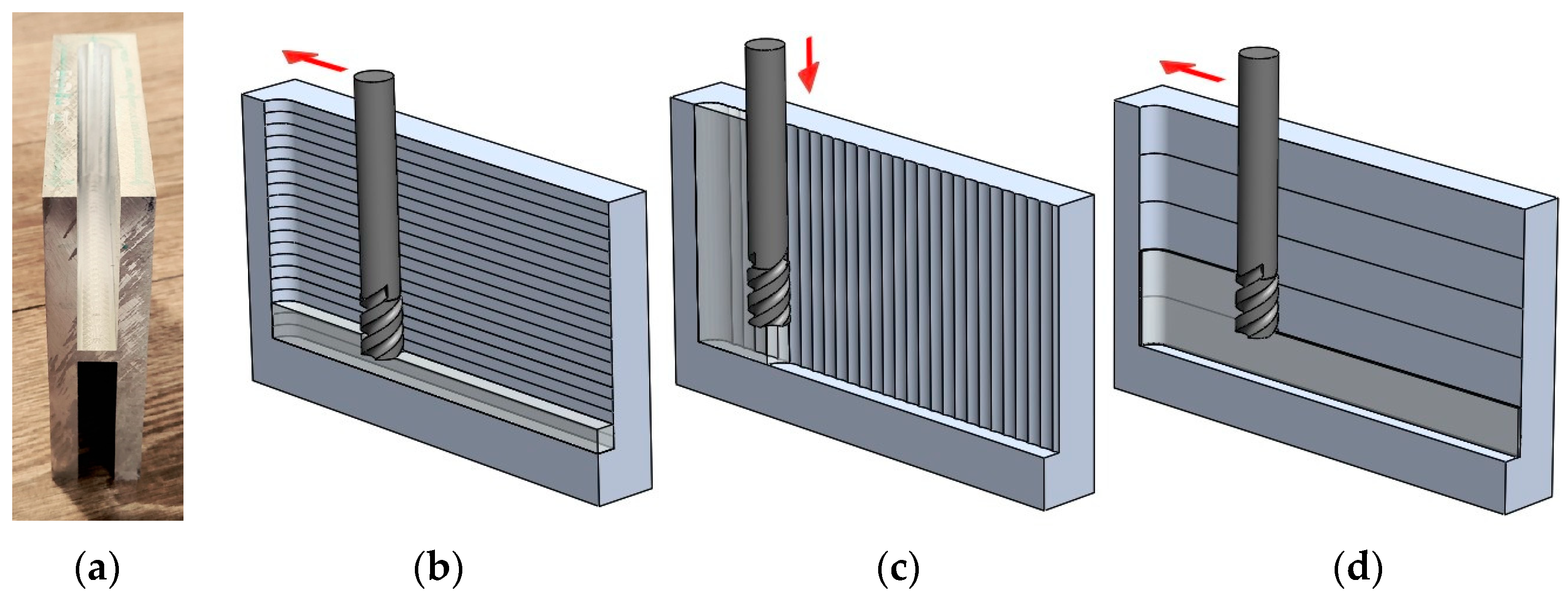
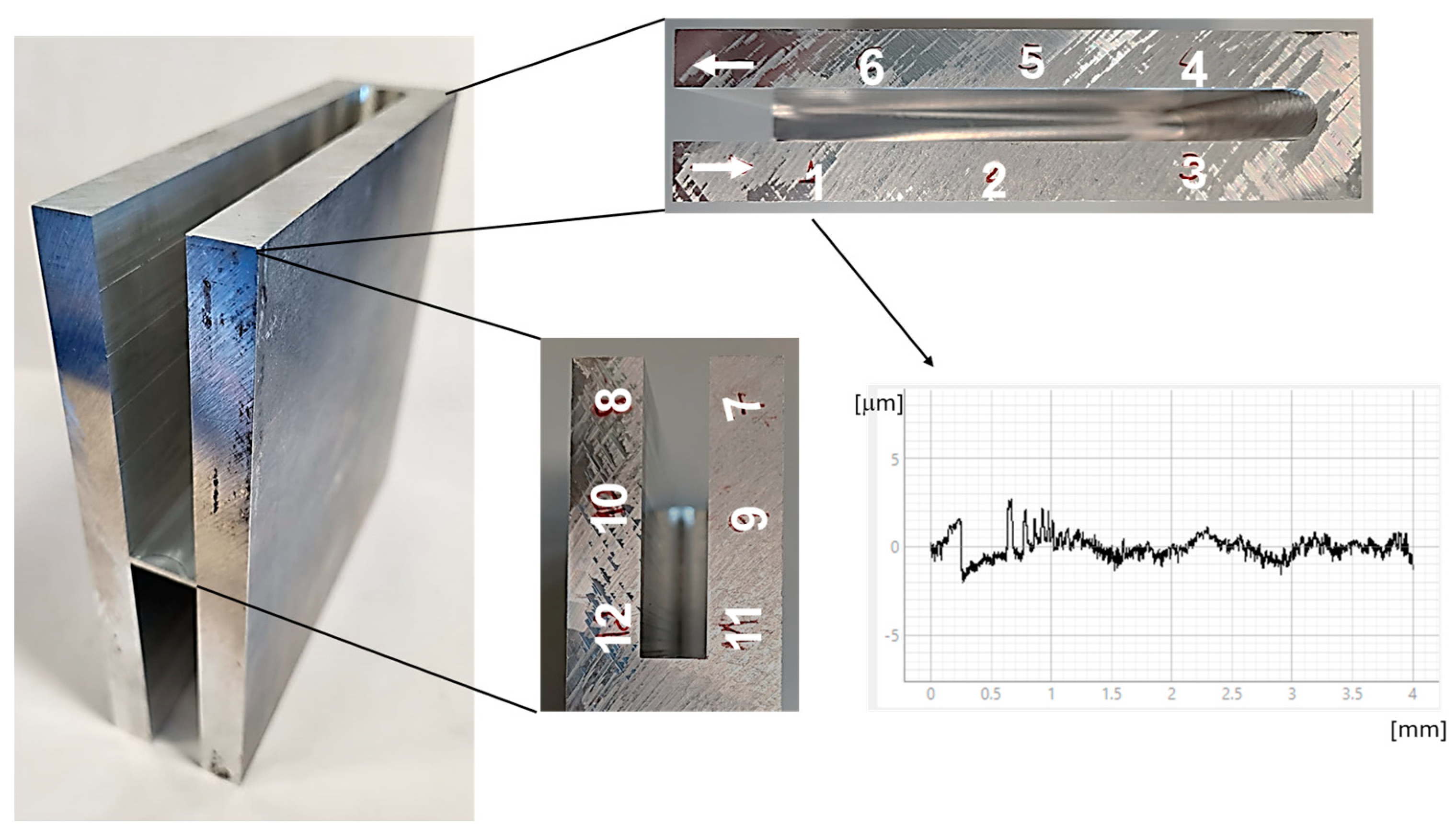
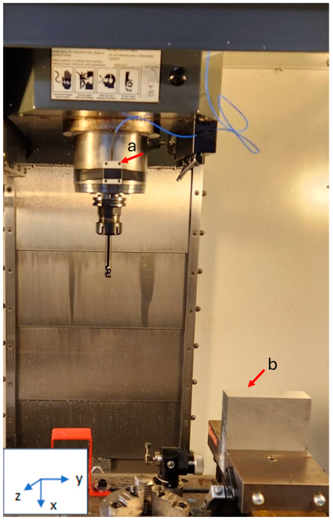
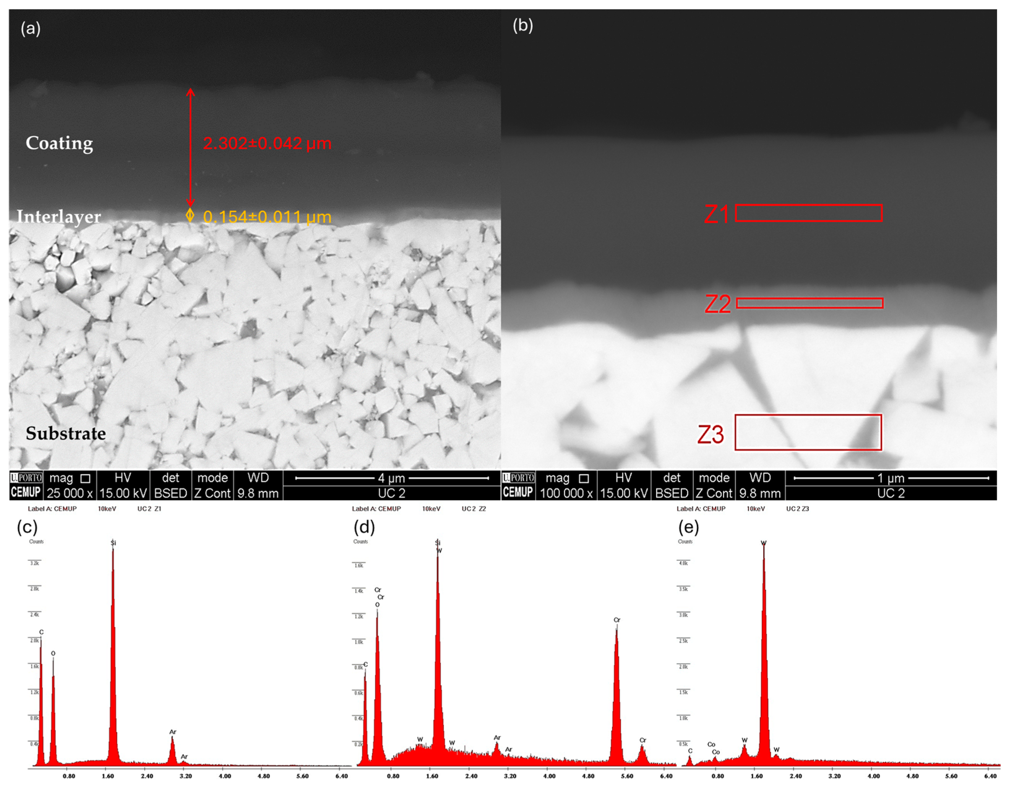
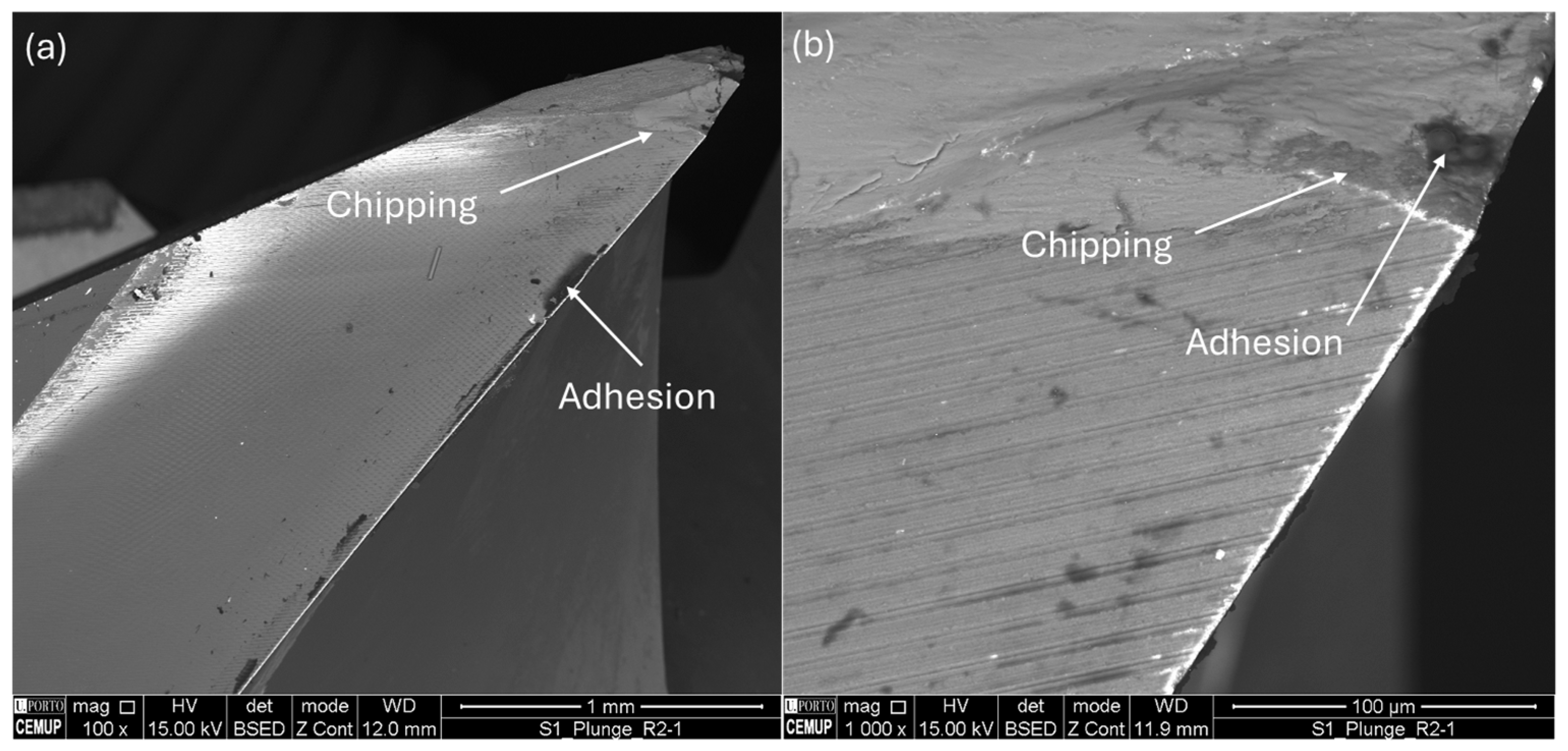

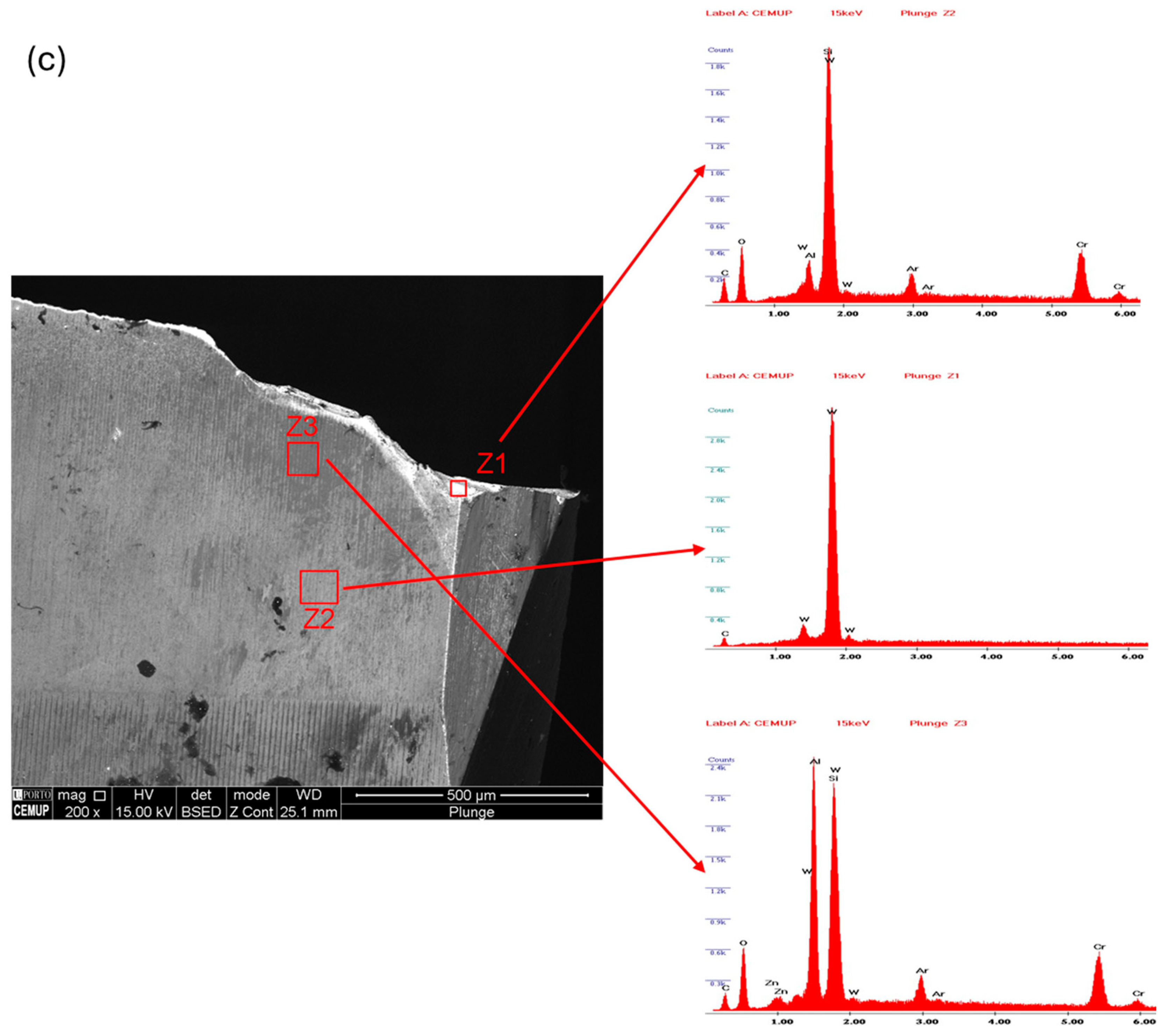

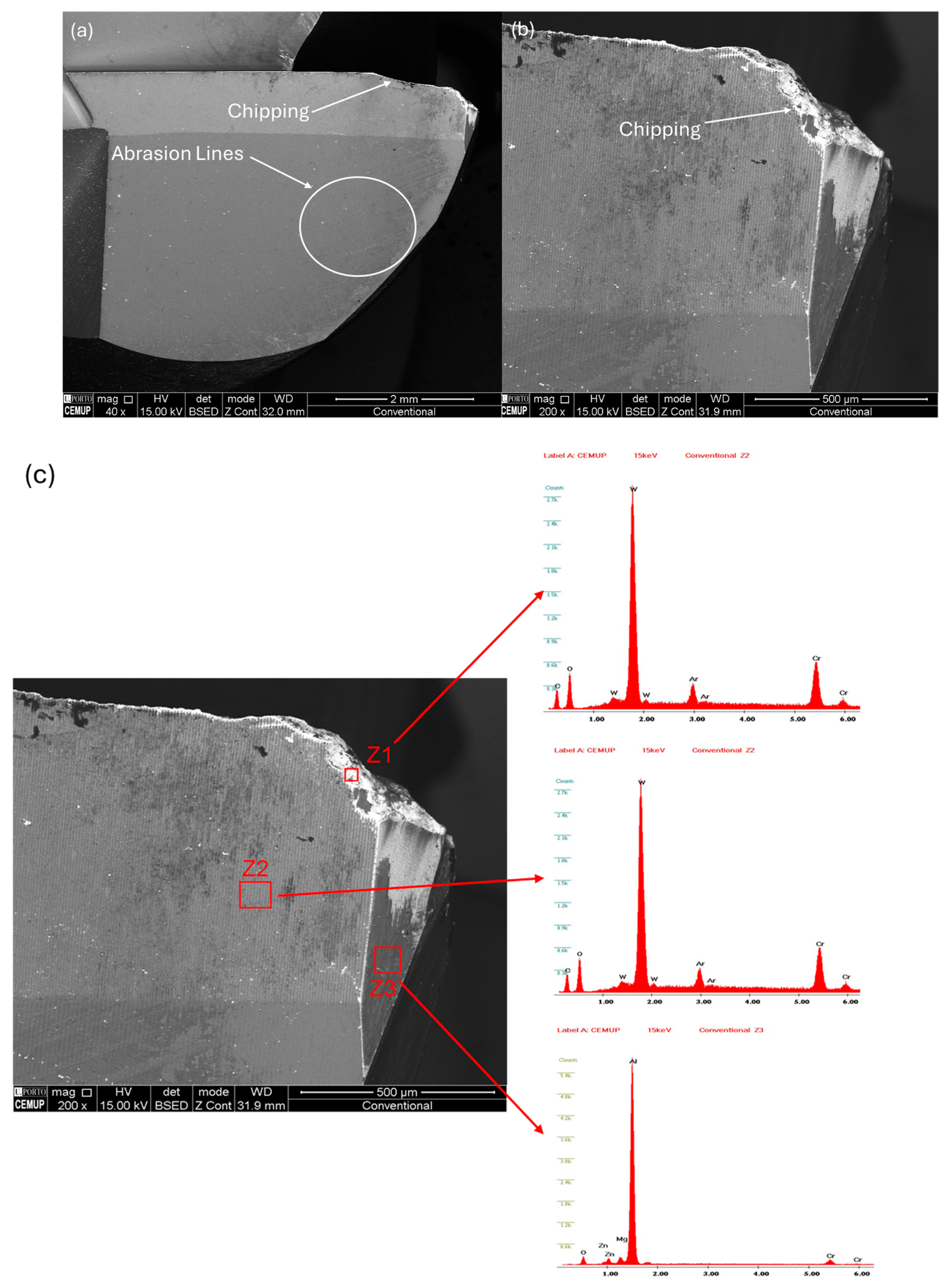
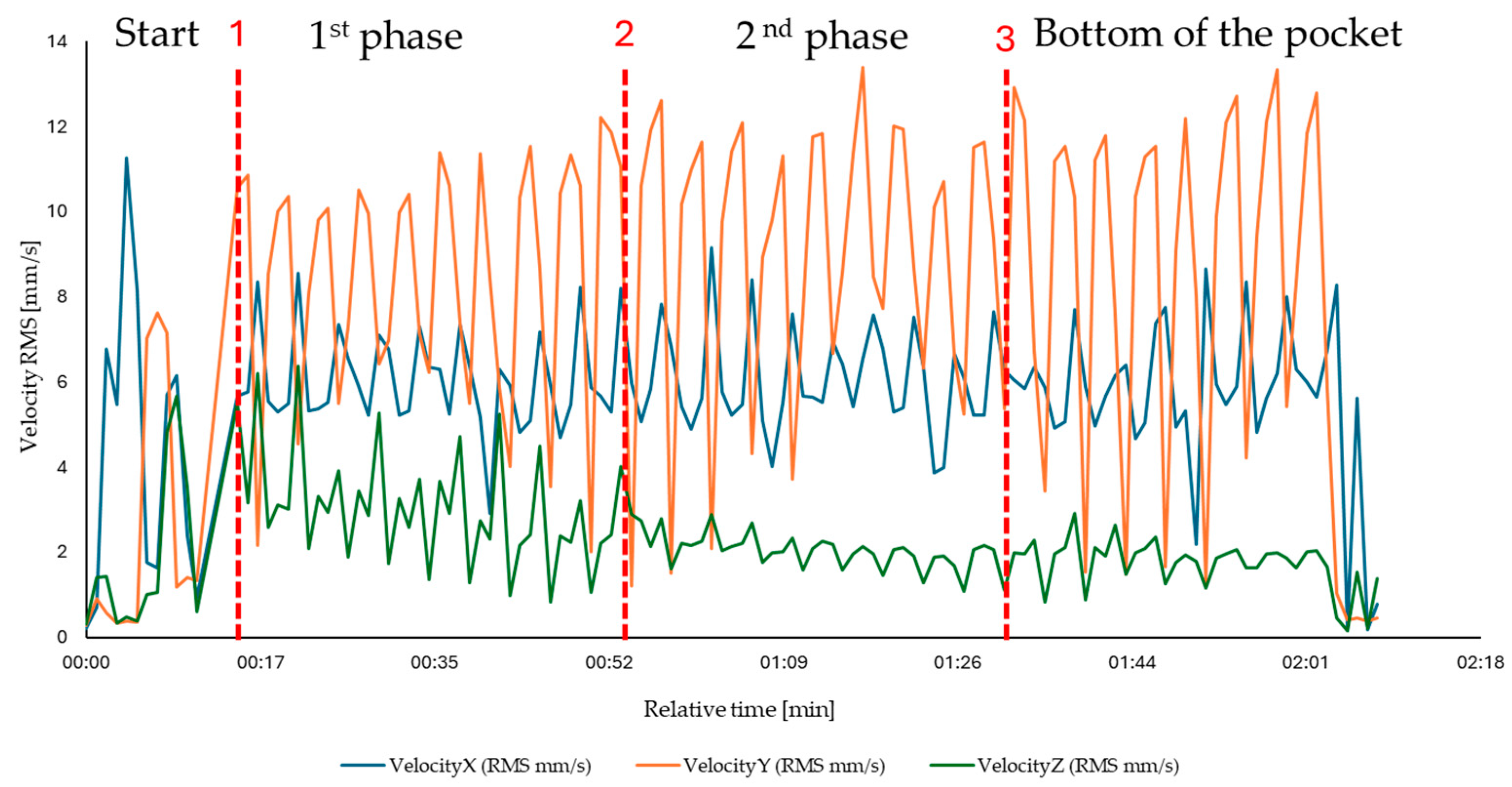
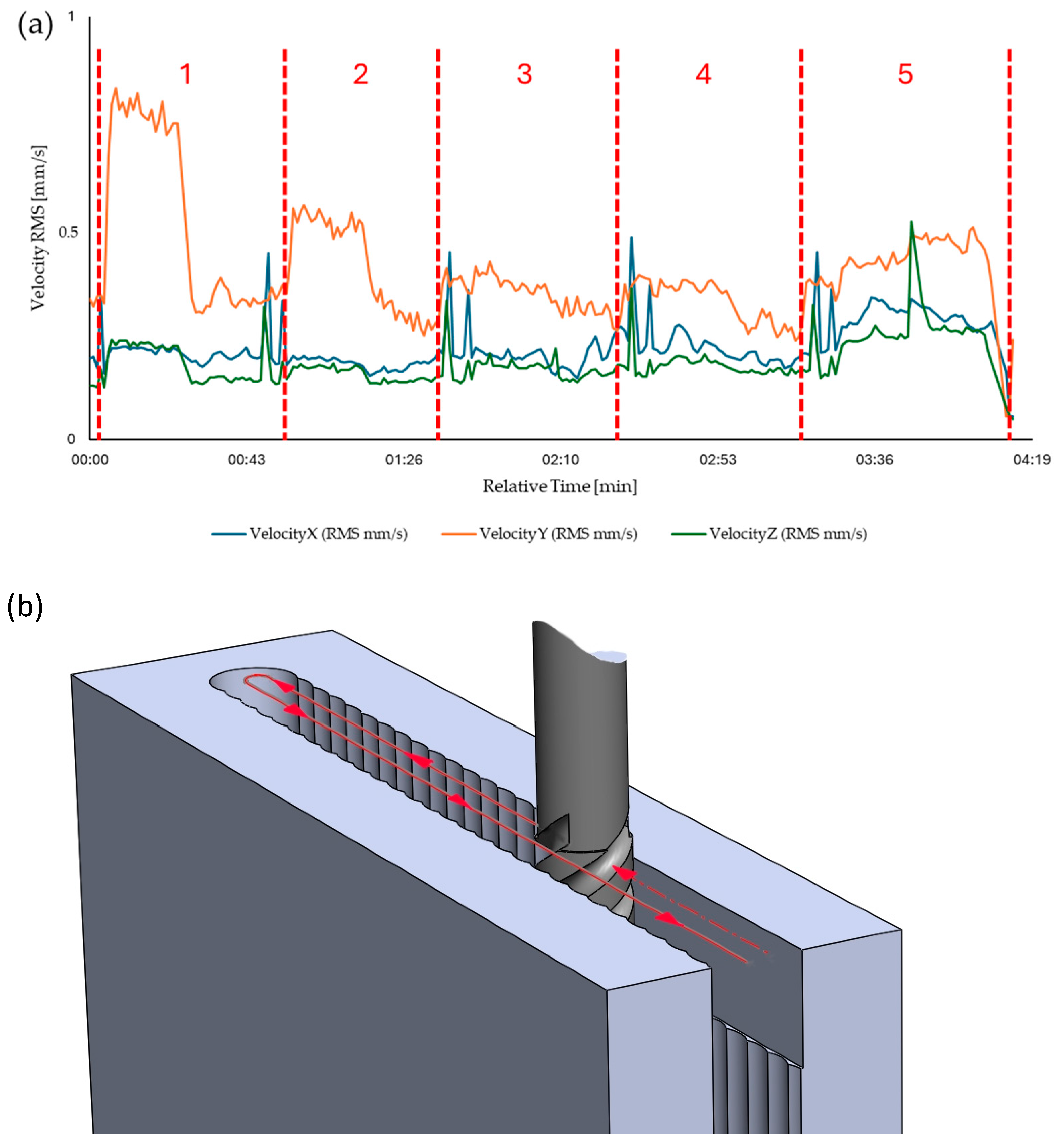
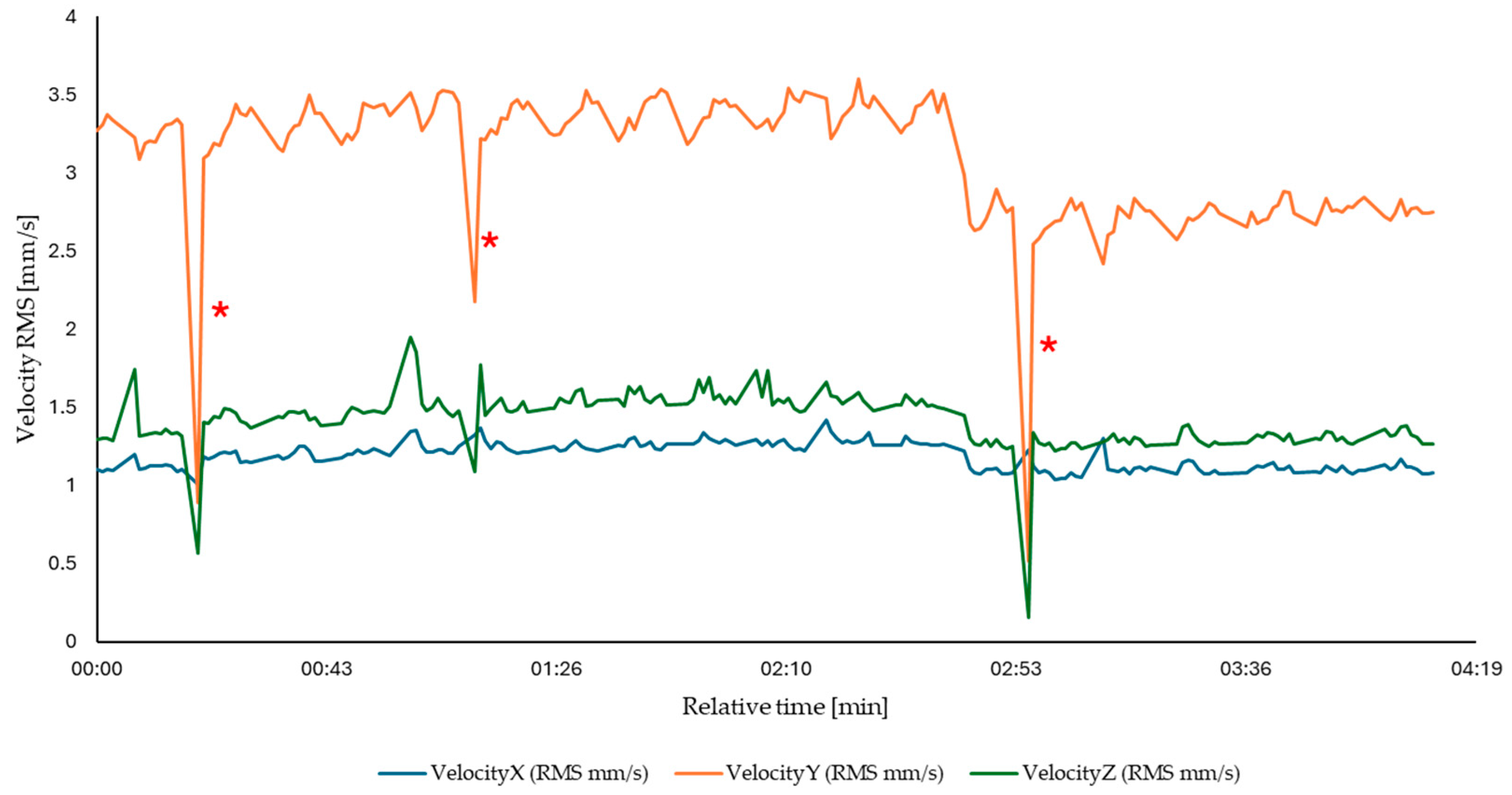
Disclaimer/Publisher’s Note: The statements, opinions and data contained in all publications are solely those of the individual author(s) and contributor(s) and not of MDPI and/or the editor(s). MDPI and/or the editor(s) disclaim responsibility for any injury to people or property resulting from any ideas, methods, instructions or products referred to in the content. |
© 2024 by the authors. Licensee MDPI, Basel, Switzerland. This article is an open access article distributed under the terms and conditions of the Creative Commons Attribution (CC BY) license (https://creativecommons.org/licenses/by/4.0/).