Abstract
Magnetic pulse welding (MPW) employs a strong pulsed magnetic field to accelerate parts against each other, thus forming an impact joint. Single-turn tool coils and field-shapers (FSs) used in MPW operate under the most demanding conditions, such as magnetic fields of 40–50 T with periods lasting tens of microseconds. With the use of conventional copper and bronze coils, intense thermo-mechanical stresses lead to the rapid degradation of the working bore. This work aimed to improve the efficiency of field-shapers and focused on the development of two- and four-slit FSs with a nanocomposite Cu 18Nb brazed wire acting as an inner current-carrying layer. The measured ratios of the magnetic field to the discharge current were 56.3 and 50.6 T/MA for the two- and four-slit FSs, respectively. FEM calculations of the magnetic field generated showed variations of 6–9% and 3% for the two- and four-slit FSs, respectively. The ovality percentages following copper tube compression were 27% and 7% for the two- and four-slit FSs, respectively. The measured deviations in the weld-joining length were 11% and 1.4% in the two- and four-slit FSs, respectively. Compared to the previous experiments on an entirely steel inductor, the novel FS showed significantly better results in terms of its efficiency and the homogeneity of its magnetic field.
1. Introduction
One of the main applications of high pulsed magnetic fields (HMFs) lasting 10–100 ms is the magnetic pulse processing of metals. These technologies provide promising results in metal forming and welding, as well as the compaction of nanopowders inside conductive shells [1,2]. The main tools for generating magnetic fields are single- or multi-turn coils or inductors, which often have field-shapers (FSs). The highest field pulse requirements are imposed by the process of magnetic pulse welding (MPW), especially for high-strength, hard-to-weld steels, e.g., ferritic–martensitic steels for use in the nuclear industry [3,4,5], in which a field of 40–50 T is generated in the inductor for a 10–20 μs half-period. The energy of the magnetic field is transferred to the kinetic energy of the metal workpiece, which leads to the collision of the parts to be welded at speeds of 300–500 m/s, forming metallurgical bonds.
Apart from the material-joining process itself, the actual aim of MPW research is to increase inductor efficiency and lifetime. For example, conventional copper and bronze (CuBe2) inductors are not capable of the repetitive generation of such fields (generating at least several hundred pulses per lifetime) [6,7,8]. Intensive thermo-mechanical stresses, especially Joule heating, in the surface layer of the inductor lead to the formation of cracks and its further destruction [9,10]. Strong materials, such as steels, can be used in inductors to increase their durability; however, this leads to other issues as the higher resistivity of steels causes the discharge current to increase, which reduces the lifetime of the coil, and this higher resistivity reduces the azimuthal homogeneity of the magnetic field. Circumferential drops in the magnetic field near gaps in the field-shaper affect the quality of the welded joint.
A nanostructured Cu-Nb alloy has proven to be the most promising material for high-field-inductor construction. This is possible due to its combination of high conductivity (50–70% IACS) and outstandingly high strength (an ultimate tensile strength of up to 1500 MPa) [11,12,13]. These properties are achieved due to its fiber structure (niobium fibers with a diameter of ∼100 nm are distributed in the copper matrix), which is obtained via an accumulative drawing and bundling (ADB) process [13,14,15]. Thus, the multi-fold generation of fields with amplitudes of up to 45 T [16], 72 T [17], 90 T [18], and 100 T [19,20,21] and durations lasting from dozens to hundreds of milliseconds were obtained in multi-turn coils made from this material. However, due to fundamental differences in the design of multi- and single-turn inductors that complicate the use of fiber composites, there have been no research works devoted to the development and study of this material for the generation of shorter magnetic field pulses.
The aim of this work was to improve the existing MPW single-turn inductor design in order to improve its performance, in particular, to increase magnetic field circumferential (azimuthal) uniformity and enhance energy efficiency, i.e. increase the ratio. The main approach in the present work is the use of the abovementioned Cu-Nb composite wire to upgrade steel inductors that worked previously. For a more comprehensive study, FEM modeling of the developed systems was carried out using Ansys Maxwell 3D.
2. The Basics of the MPW Process and the Role of the Field-Shaper
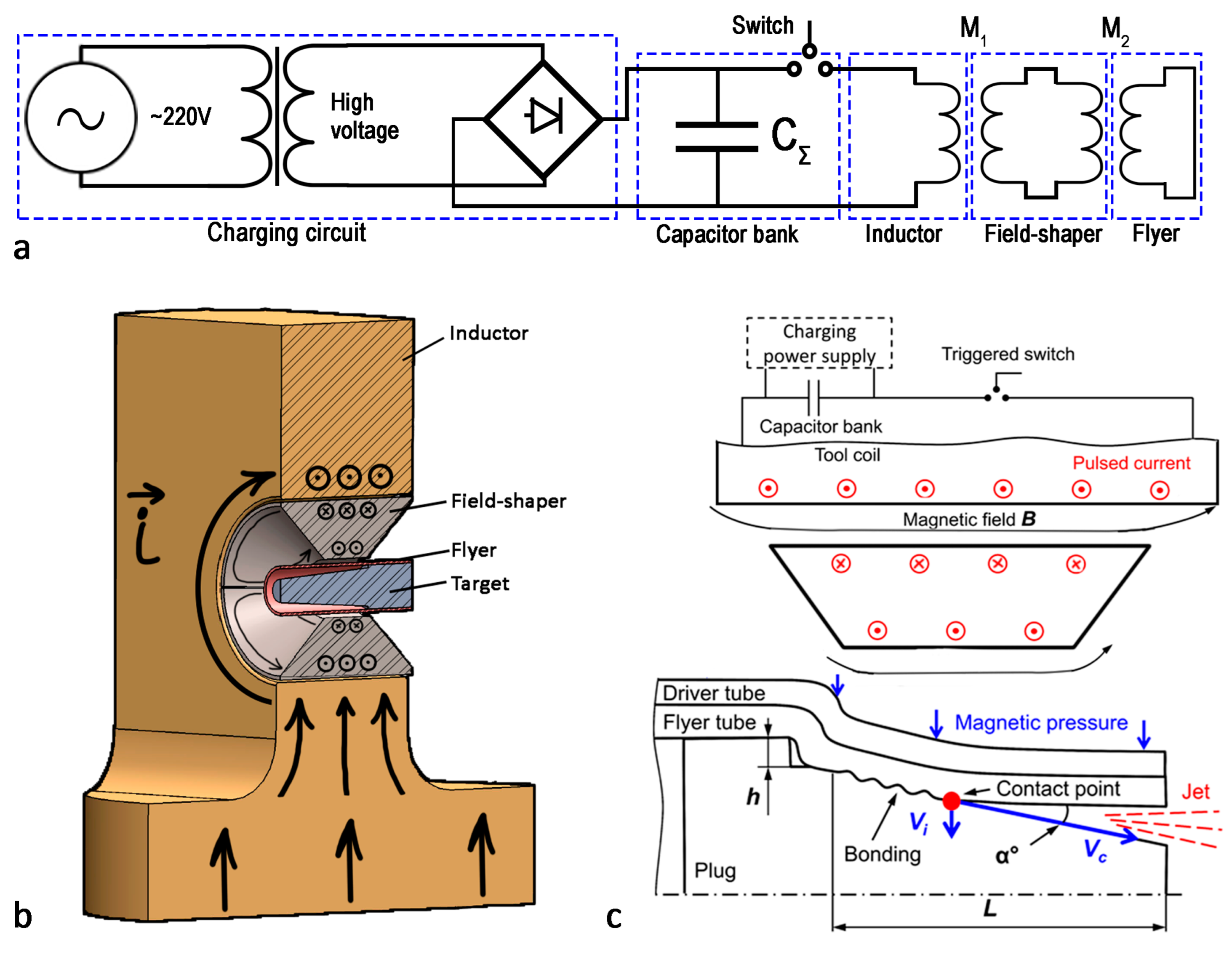
The MPW setup (Figure 1) consists of a pulse current generator (PCG) which is loaded to a coil with a field-shaper and a workpiece inside (Figure 1a). Once the capacitor bank is charged to the required energy level, it is switched to the coil via triggered vacuum switches. The discharge current forms a magnetic field in the working bore (channel) of the inductor, which induces eddy currents in the field-shaper and the workpiece (Figure 1b). The Lorentz force () generated from the interaction of the magnetic field with the induced currents creates pressures of up to 2 GPa (70 T) on the workpiece, which makes it possible to carry out its radial compression at velocities measuring hundreds of m/s.
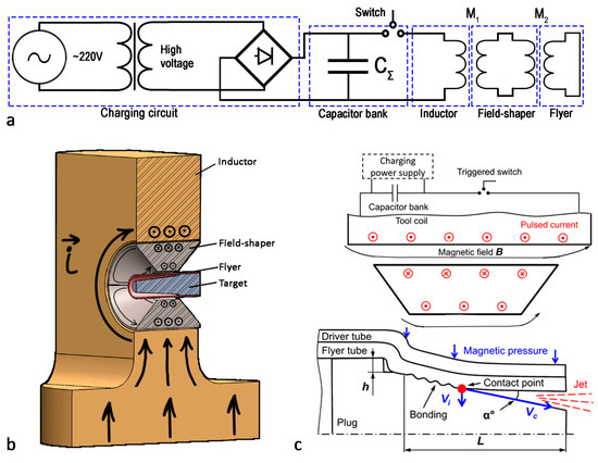
Figure 1.
MPW setup schematics: electrical schematic (a); single-turn inductor with FS (b); joining geometry (c).
To achieve a high-quality joint, it is necessary that the impact velocity and the contact point velocity (Figure 1c) are within a certain range of values known in the literature as the welding window [22,23,24]. The radial compression of a cylindrical conducting tube can be described in a one-dimensional (axisymmetric) model using the following equation:
where is the specific area of the tube, is the radial acceleration of the middle of the tube wall, is the pressure required for the plastic deformation of the tube, and is the pressure of the magnetic field created by the discharge current at a frequency :
In order to describe the radial compression velocity, it is necessary to integrate Equation (1) over time (from the initial moment of discharge, t = 0, to the moment of the tube–plug collision, t = ):
This equation shows that the velocity of the tube wall is proportional to the square of the magnetic induction B. In the case of a real inductor system, the magnetic field pressure may differ at different points on the surface. Thus, a 10% difference in magnetic field induction will lead to an approximately 20% difference in radial velocity.
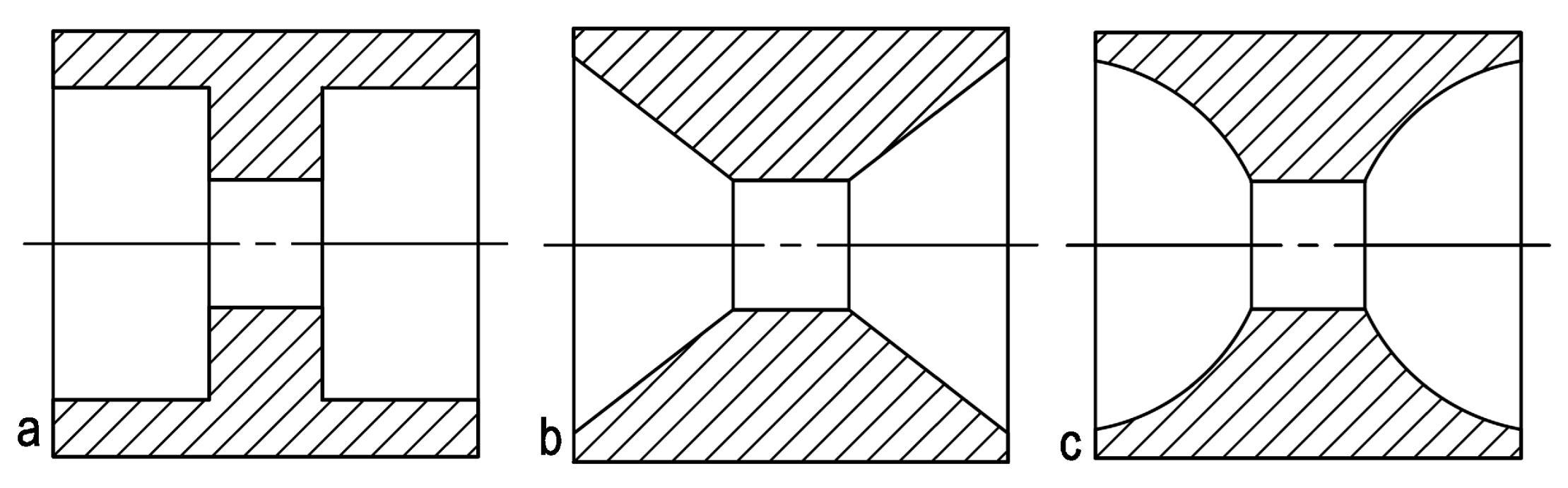
Accordingly, the optimization of the inductor system design to increase field homogeneity on the surface of the workpiece is a highly urgent task. The magnetic field experiences drops near gaps in the field-shaper, so a common approach to achieving a smooth azimuthal magnetic field distribution is to increase the number of gaps or slits in the FS (Figure 2). This approach is practiced for both planar and cylindrical geometries [25,26]. Four slits, according to these works, was found to be optimal; this was confirmed experimentally. The position of the FS in the inductor also affects the homogeneity of the magnetic field. Through the work of Shen’s team, it was shown that the most uniform compression of an aluminum alloy tube was achieved when the angle between the plane of the FS slit and the plane of the inductor slit was 90° [27].
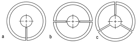
Figure 2.
Field-shaper for cylindrical geometry with different numbers of slits (1 (a), 2 (b), and 3 (c)).
Another task is to generally increase pulsed magnetic field generation efficiency and homogeneity, which are related to FS geometry. Thus, to achieve these results, a possible approach is changing the FS cross section. Rajak and colleagues investigated a stepped (Figure 3a) and tapered (Figure 3b) cross-sectional FS profile [28,29]. The work showed that a single-stepped profile provides the best peak field for the same charging energy; however, using a stepped design reduces its overall stiffness. A similar study of plane geometry was carried out in the work of Zhang [30]. Chen and colleagues [31] analyzed the different cross-sectional shapes and inner surface angles of FSs and suggested the use of a rounded shape as an intermediate between stepped and tapered shapes. The results of numerical simulations and experiments have shown that changing the shape from conventional and tapered (similar to Figure 3b) to concave (Figure 3c) could increase the magnetic field flux by ∼10% with virtually no loss in strength.

Figure 3.
Schematic of different shapes of field-shaper cross-sections: stepped (a), tapered (b), and concave (c).
It should be noted that the use of FSs is not necessary for the technology; however it has advantages. It is replaceable, so it increases the service life of the inductor, and different field-shapers may be used to fit workpieces of different sizes.
3. Materials and Methods
3.1. Field-Shaper Design and Testing
In this work, we used a 2 × 8 mm nanostructured Cu-Nb composite wire produced by Rusatom MetalTech LLC., Moscow, Russia [13]. Copper–niobium alloy wires (containing 18% Nb) were cold-drawn in a copper shell, thus forming polygonal cross-section filaments, as can be seen in the Figure 4. The initial wire had the following characteristics: its resistivity was 2.8 μOhm·cm, its yield strength was 860 MPa, and its tensile strength was 1260 MPa.
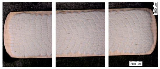
Figure 4.
Cross-section of Cu-Nb rectangular wire (edges and central part).
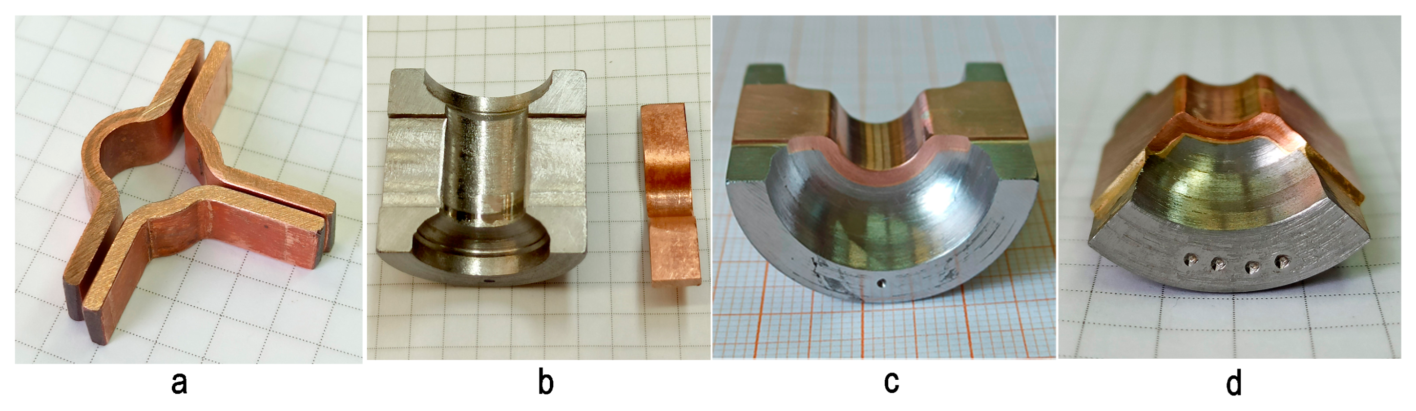
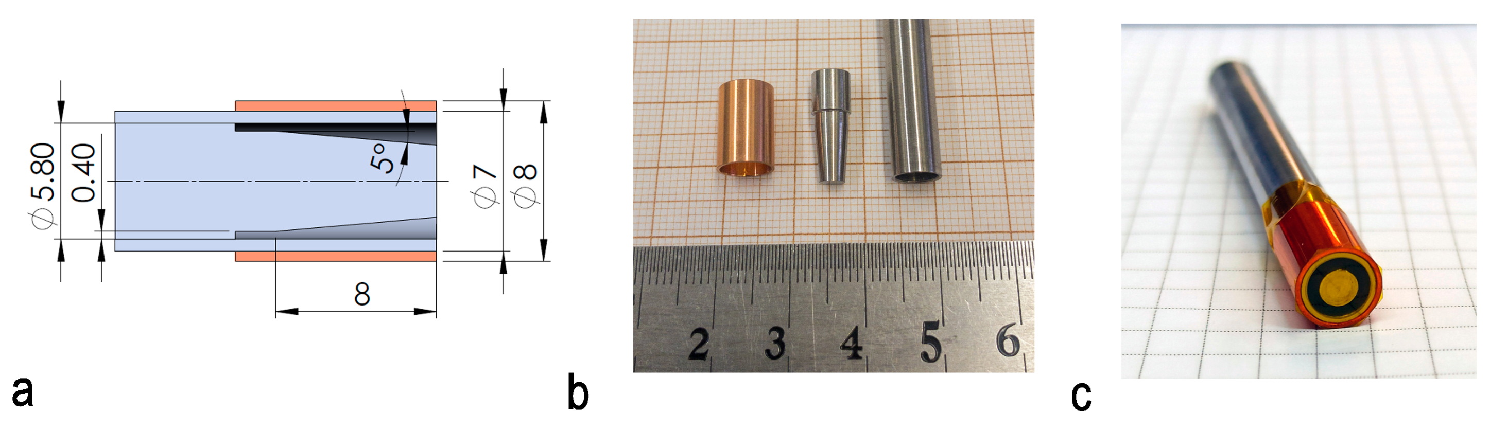
The wire pieces were annealed in an air atmosphere at 700 °C for 8 min, followed by cooling them in water. After annealing, they were cold-deformed at room temperature using a punch and die into and W-shaped parts with a central angle of 180° for a two-slit FS and 90° for a four-slit FS (Figure 5a).The obtained Cu-Nb wire was brazed to the inner surface of the 30KhGSA FS body (Figure 5b) using PSr-40 hard solder (40% silver, 26% cadmium, 17% copper, 16.7% zinc, and 0.3% nickel), with the direction of the fibers oriented along the current lines (Figure 5c,d).

Figure 5.
Parts of the field-shapers before (a,b) and after brazing, machining, and grinding (c,d).
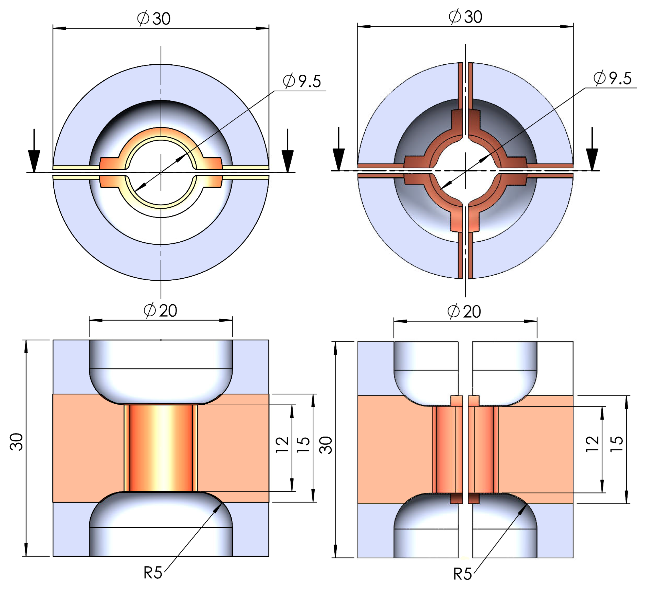
After short-term annealing in air and brazing, the yield strength of the wire was reduced to 515 MPa, and the tensile strength was reduced to 890 MPa [32]. After brazing, the FS parts were milled and ground to the following final dimensions: an outer diameter of 30 mm and a length of 30 mm. The bore (channel) dimensions were as follows: a diameter of 9.5 mm and a length of 12 mm, with a 5 mm radius rounding off the transition to the coil’s working bore (Figure 6).
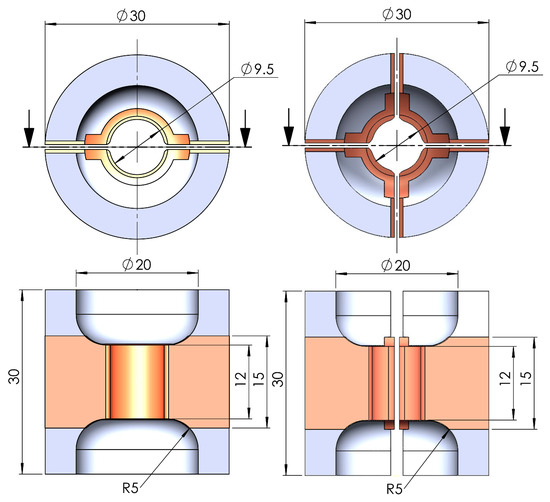
Figure 6.
Constructions of FS.
3.2. FEM Modeling of Magnetic Field Generation with Different Field-Shapers
To determine the magnetic field distribution in inductor systems with FSs of different types and to validate the experimental results, FEM calculations were performed using the Ansys Electronics Desktop 2021 R2 (Ansys ED) software package in the Maxwell 3D module. The current was given as a sine function of time:
where T is the period of the electromagnetic (EM) field oscillations, taken equal to 28 μs (as in the experimental setup); the maximum current was set so that the maximum magnetic field was equal to 40 T. The calculations were performed in time until the first magnetic field maximum was reached at t = 7 μs. The time step in the calculation was 0.1 μs.
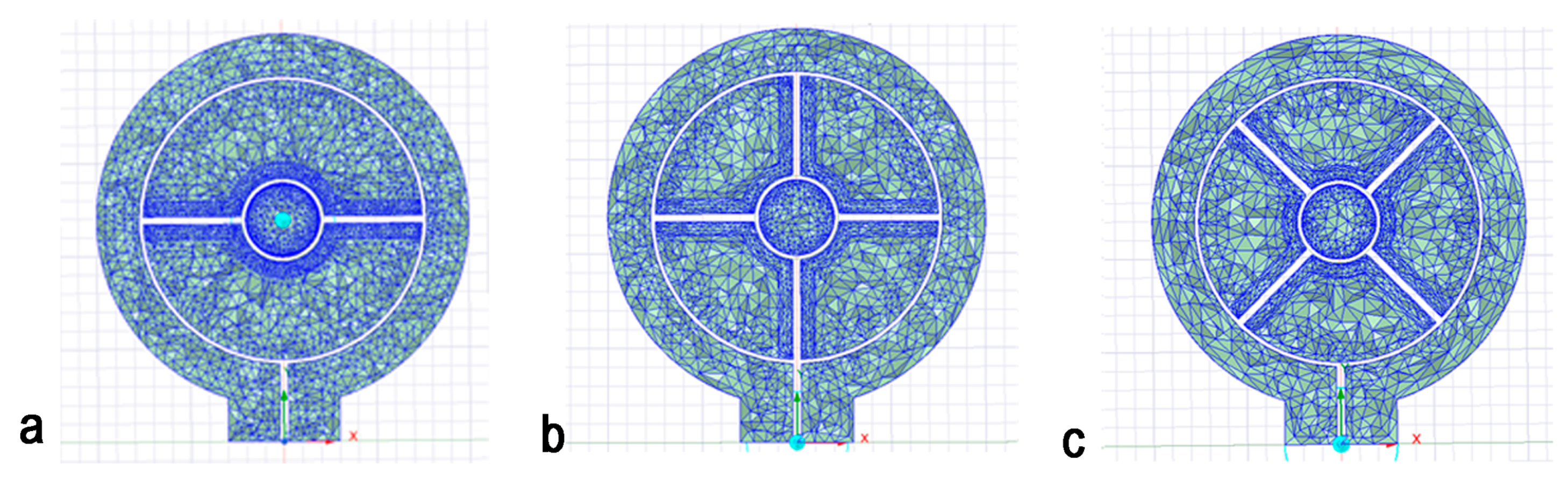
The sizes of the inductor and FS and the physical properties of their materials were the same in the calculations and experiments. Resistivity values of 45, 1.72, and 2.8 μOhm·cm were measured via the four-probe DC method for 30KhGSA steel, copper, and the Cu-Nb composite, respectively. The relative magnetic permeability of steel μ was assumed to be 1 since the calculation was performed for magnetic fields much higher than the magnetization limit of steels. Meshing was performed using built-in Ansys ED tools. Three geometries were studied (A, B, and C), and the final mesh is shown in Figure 7. In each one, the plate material was either Cu-Nb or 30KhGSA steel.
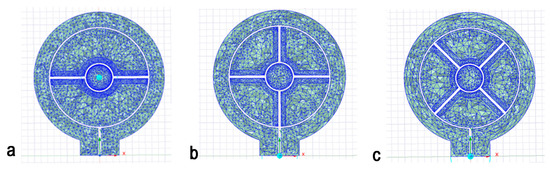
Figure 7.
FS geometries studied: two-slit FS (a), four-slit FS with slits perpendicular to inductor (b), and four-slit FS with a 45° slit angle (c).
3.3. Experimental Study of Magnetic Field Generation
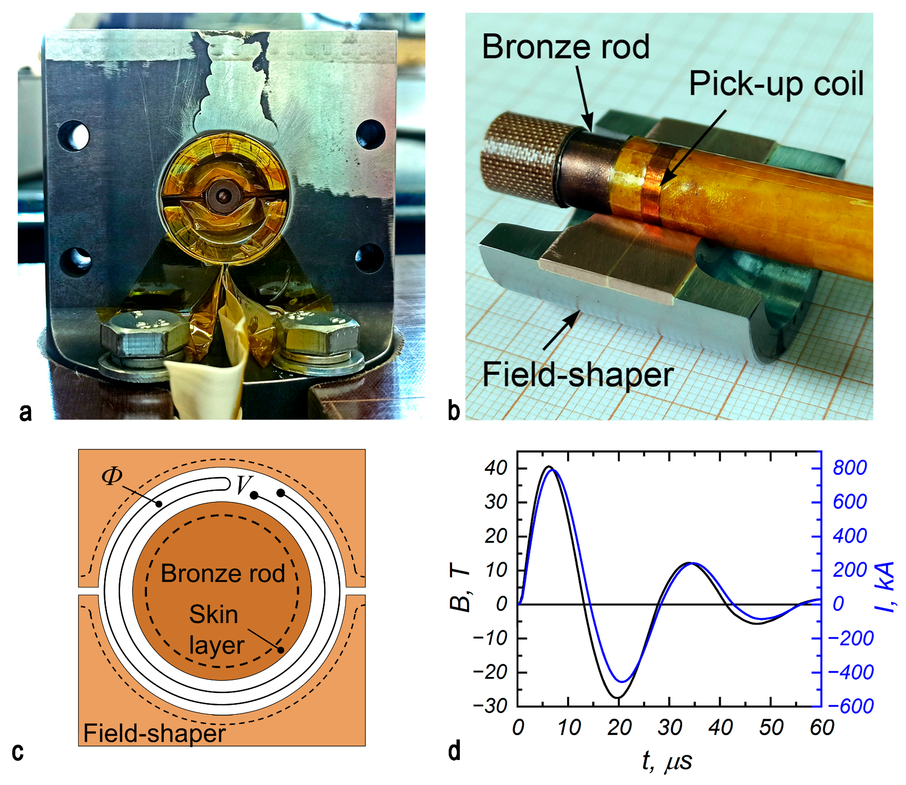
The manufactured system comprising the inductor and FS was tested under the generation of an HMF with an amplitude of 40 T and a half-period duration of 14 μs (Figure 8). A pulsed current generator (PCG) with a capacitive-type storage device was used in this work. The parameters were as follows: capacity C = 425 μF, intrinsic inductance = 15 nH, intrinsic resistance = 1.5 mOhm, and a charging energy of up to 135 kJ. The generator supplied pulsed currents of up to 2 MA to the inductor. In the discharge circuit, these high currents were measured using a Rogowski coil, while the magnetic fields on the workpiece surface were measured using a pick-up coil (Figure 8b,c).
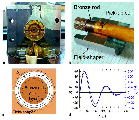
Figure 8.
Field-shaper with magnetic field sensor inside coil (a); pick-up coil (b); schematic of covering bronze rod inside-shaper (c); typical magnetic field induction and discharge current time dependencies (d).
In order to carry out repeated measurements, a rod of CuBe2, measuring 8.55 mm in diameter, was inserted into the field-shaper instead of a MPW workpiece. Beryllium bronze was chosen because of the combination of its low resistivity, 6.5 μOhm·cm, and high yield strength, 600–950 MPa. A loop-shaped inductive magnetic field sensor (Figure 8c) was installed axially in the middle of the inductor channel. It covered an area measuring 5 mm2 of the magnetic flux inside the inductor channel. The actual magnetic field, given in teslas, was calculated by integrating the voltage from the sensor, which was recorded by an oscilloscope (Figure 8d).
The magnetic field amplitudes in the MPW experiments were calculated using the ratio from the above measurements, taking into account the thickness of the outer layers of the materials of the field-shaper, bronze rod, and copper driver and the heating effect of eddy currents on the conductivity of these parts. While the tube is moving in the MPW, the current flowing through the parts and the magnetic field in the gap are redistributed, which may be the topic of a later study; therefore, the field in this experiment was calculated under the assumption that the shell does not move.
3.4. Magnetic Pulse Tube Forming and Welding
The distributions of the magnetic fields in the developed systems were characterized experimentally by compressing empty tubes and performing magnetic pulse welding using the field-shapers produced. The empty tubes were made of annealed copper (Cu-DHP) and measured 9.5 mm in outer diameter and 0.85 mm in wall thickness.
Finally, the joining of steel tubes to plugs was performed using the developed field-shapers. The tubes and plugs were made of STS410 (an analog of AISI410), a heat- and corrosion-resistant steel often used in heat and hydraulic engineering. Its chemical composition is presented in Table 1. The tubes had an outer diameter of 7 mm and a wall thickness of 0.6 mm. The end plugs’ geometry is shown in Figure 9. A 0.5 mm thick copper driver was used to more efficiently transform the magnetic field energy into the kinetic energy of the steel tube. The plug-tube–driver configuration replicated a configuration used in our previous work in order to determine differences in joint quality associated with inductor system design [33].

Table 1.
Chemical composition of STS410 steel.
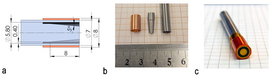
Figure 9.
Joining geometry: the tube, plug, and driver (a) and a picture of the parts (b,c).
To investigate the impact of magnetic field inhomogeneity on the quality of the welded joint, the parts were cut along the axis in the planes with the maximum and minimum field amplitudes.
4. Results and Discussion
4.1. FEM Analysis
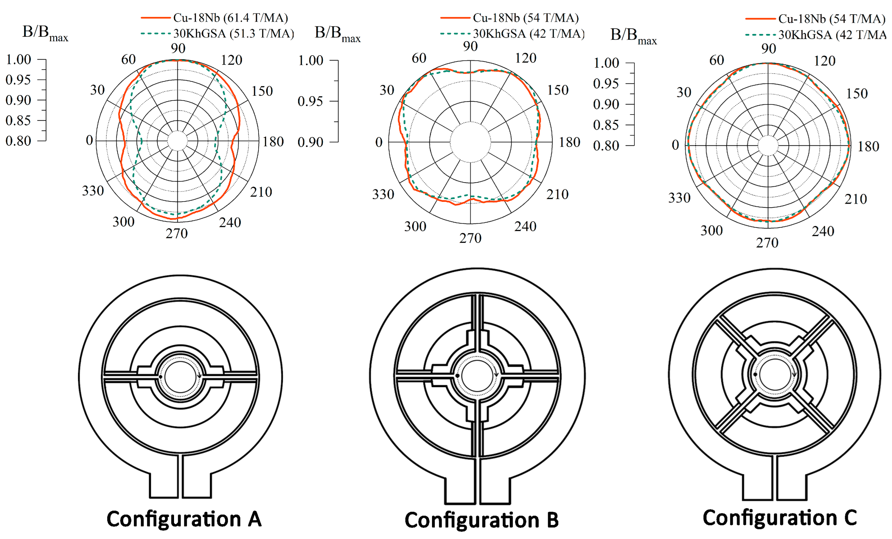
The FEM study of magnetic field generation processes in inductors with FSs showed the following results. (Figure 10) The ratio of the magnetic field maxima in the cylindrical part of the gap between the FS and the inserted rod to the current in the primary inductor coil was as follows for the FS with a Cu-Nb plate: 61 T/MA in the two-slit FS and 54 T/MA in the four-slit FS for both installation angles; for the FS composed entirely of 30KhGSA steel, these ratios were 51 and 42 T/MA, respectively. The use of a Cu-Nb brazed plate instead of an entirely steel FS resulted in a significant increase in the ratio of the inductor by about 20% in the two-slit FS and 29% in the four-slit FS due to thinner outer layer of the Cu-Nb material compared to steel.
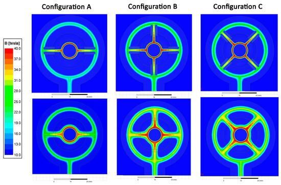
Figure 10.
Field distribution in different inductor systems: Cu-18Nb plate in the top row on the FS surface; 30KhGSA plate in the bottom row.
The azimuthal distribution of the field in the gap is plotted along a line displaced by 0.2 mm from the surface of the copper rod to exclude the influence of mesh defects. (Figure 11). In configuration A, the largest field drops are observed at angles 0 and 180°, corresponding to the gaps between the FS parts. The difference between the maximum and minimum field values in such a system with a copper-niobium plate is 6%. Replacing the plate with 30KhGSA steel leads to an even greater decrease of 9%. Consequently, the magnetic field pressure (P ∼), on the workpiece will decrease by 12 and 17%, respectively.
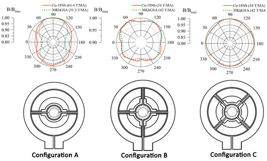
Figure 11.
The azimuthal distribution of the magnetic field for different inductor system configurations.
Increasing the number of FS segments effects the homogeneity of the magnetic field—regardless of the position of the gaps and even the material, the difference between the maximum and minimum field values will be about 3%, which is a 6% difference in magnetic pressure. These results have shown that although the use of steel reduces inductor efficiency, it is possible to obtain a sufficiently homogeneous field in a steel FS by increasing the number of its parts.
Similar distributions for cylindrical geometry can be found in [26]. There, in order to exclude the influence of thermal effects and workpiece deformation on the magnetic field distribution, the pressure distribution at the moment of time when the radial compression was minimal was presented. The values that could be obtained from their plots are as follows: 8% electromagnetic force inhomogeneity in a two-slit FS and 3.3% in a four-slit field-shaper. Their distributions were more uniform than ours since they used a primary winding and a field-shaper made of copper. Copper parts have low resistivity; however, they can operate repeatedly in magnetic fields not exceeding 20 T. The main difference in our systems is that we used a single-turn primary coil composed of less conductive steel and a less-conductive steel FS with a Cu-Nb composite. Our field-shapers are designed to withstand at least tens of pulses of 50–60 T magnetic fields. Another difference is the magnetic field rising time, which was 160 μs in Yan’s work and 6 μs in ours. The magnetic field rising time imposes restrictions on the dimensions of the parts; so, in our case, minimal inductance is required.
4.2. Magnetic Field Generation
The measured ratios of the peak magnetic field to the peak battery discharge current were 56.3 T/MA for the two-slit FS and 50.6 T/MA for the four-slit FS. These data were collected at the 40 T peak of the magnetic field with the above-described inductive sensor. This is the same technique we used in [34], which yielded a ratio of 43 T/MA in a 30KhGSA steel two-slit field-shaper. In the homogeneity experimen, the compressed empty copper tubes and their cross-sections after a 48 T/14 μs magnetic field pulse are presented in Figure 12.
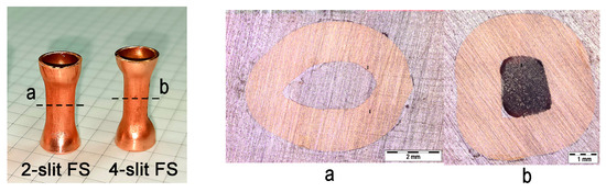
Figure 12.
Deformed empty copper tubes after a 48 T/14 μs magnetic field pulse.
To describe the azimuthal homogeneity of the magnetic field pressure applied to the copper tube, we used a uniformity coefficient, , and the calculated values are presented in Table 2:
where is the maximum diameter and is the minimum diameter of the deformation center (Figure 13).
Table 2.
Characteristics of compressed Cu tube.
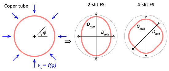
Figure 13.
Tube profile schematic before and after compression.
The results of the forming experiment demonstrate the inhomogeneities in the magnetic field in the FS. Thus, less-deformed tube sections corresponded to the gaps in the FS with minimums in the calculated magnetic field. The obtained values of the inhomogeneity coefficient were 27 and 7%, while Yan’s were 3–9% for a multi-slit FS at an energy per pulse similar to ours. Despite differences in the magnetic field rising time and the material of the tubes, the results are comparable. Increasing the number of parts/slits leads to a significant improvement in tube compression uniformity.
4.3. MPW Experiment
The ends of the samples after MPW retained the imprint of the field-shaper in which they were welded (Figure 14).

Figure 14.
Samples after MPW; before and after Cu driver peeling.
Cut, ground, and polished samples were studied by optical microscopy, using an Olympus BX41M microscope. The cut planes are shown in Figure 15. Plane 1 coincided with the inductor slit, and plane 2 is rotated at 90° to plane 1 for the two-slit FS and at 45° to plane 1 for the four-slit FS. Each image in Figure 16 displays a cut of one sample in these two planes: plane 1 for the top specimen, and plane 2 for the bottom specimen. Under microscopic examination, the weld appears as a fusion of the tube and the plug. A discernible dark line indicates a gap between the parts, or the area where they are not welded. The fusion lengths and of the weld joint in the high- and low-field-amplitude areas were visually determined and summarized in Table 3. The lengths of the welded joint are close to each other in planes 1 and 2 of higher and lower magnetic pressure, which indicates the good circumferential symmetry of MPW in these field-shapers. The torn-off ends of the plugs indicate a slightly excessive magnetic pressure during MPW; however, this did not affect the symmetry of the processed samples.
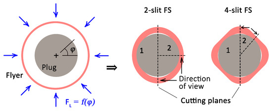
Figure 15.
Scheme of sample preparation after MPW.

Figure 16.
Optical microscopy of welded samples in different FSs: (a) two-slit FS; (b) four-slit FS.
Table 3.
MPW parameters and lengths of welded joints.
In previous work, we joined STS410 steel parts in an all-steel single-turn inductor without a field-shaper [33]. In comparison to the average joining length between samples welded at 8.5 kV in [33], the samples obtained in the present work with a four-slit field-shaper are more symmetrical, which can be seen from the relative differences in weld length in Table 3.
Magnetic pulse welding experiments have shown the significant effect of magnetic field uniformity on quality. In the worst case, a difference in pressure in the tube leaves an unbonded edge while the opposite edge of the workpiece is welded. This problem is the a research subject of various works, as described in [35,36]. In Yan’s work mentioned above, it is clearly shown that increasing the number of gaps and, as a consequence, the field homogeneity, allows one to get rid of localized welding defects [26]. In our case, this effect is demonstrated in the reduction in the difference between the joint lengths in the high-field and low-field areas of the workpiece.
Another important result is the possibility of using a nanostructured Cu-Nb alloy to modify a steel FS. The rejection of steel FSs in favor of copper, bronze, or aluminum FSs is a forced measure and is caused by the low field homogeneity of steel inductor systems. However, solid FSs of copper or beryllium bronze fail rather quickly when welding steel parts due to FS geometry changes or crack development during the first few magnetic field pulses [7,10,31]. In our case, after 10 pulses of a 40–50 T magnetic field, the was no significant evidence of surface destruction or plastic deformation. In detail the evolution of the Cu-Nb composite in similar magnetic fields can be found in our previous paper [32].
5. Conclusions
In the present work, a new approach was attempted: using a nanostructured Cu-18%Nb composite wire in field-shapers for a high pulsed magnetic field with a microsecond duration. We performed FEM modeling of the field distribution as well as field generation experiments with an amplitude of up to 48 T and a half-period of 14 μs. The considered inductor systems have a number of advantages over the most common steel and bronze ones.
- The use of a composite Cu-Nb wire led to an improved efficiency in the inductor system: the field-to-current maximum ratios were 56.3 T/MA for the two-slit FS and 50.6 T/MA for the four-slit FS, which are 31 and 18% higher, respectively, compared to the 43 T/MA ratio of an entirely steel FS. The experimental values were confirmed by an FEM analysis.
- In comparison with bronze field-shapers, Cu-Nb ones have longer lifetimes, being able to withstand at least tens of 50 T magnetic field pulses, whereas the bronze ones experience considerable thermal cracking after 5–10 pulses of a 50 T magnetic field.
- The use of a highly conductive composite material improves magnetic field homogeneity in the azimuthal direction inside the working channel of the two-slit FS: the difference between the maximum and minimum field values was 6% for the composite FS versus 9% for the steel FS (FEM).
- The magnetic pulse welding of a stainless STS410 steel tube and plug was performed using the new FS. An examination of the welds in areas of maximum and minimum field amplitude indicated a high level of azimuthal homogeneity in the obtained joints. The relative difference in weld lengths was 11% mm for the two-slit FS and 1.4% for the four-slit FS. This is higher than the 16% measured for the steel coil presented in the previous work.
Author Contributions
This study’s conception and design were performed by V.K., A.S. and S.P. The development of the inductor system and experimental work were performed by V.K. The FEM analysis was performed by E.Z. Sample preparation, data analysis, including the literature review, and figure and scheme preparation were performed by V.K. and E.Z. The original draft was prepared by E.Z. Supervision, project administration, and funding acquisition were performed by V.K. All authors have read and agreed to the published version of the manuscript.
Funding
This research was funded by the Russian Science Foundation (RSF) under Grant No. 22-79-00307, https://rscf.ru/en/project/22-79-00307/ (accessed on 20 March 2024).
Data Availability Statement
The data presented in this study are available upon request from the corresponding author.
Acknowledgments
These studies were carried out using equipment at the common use center “Electrophysics” on the basis of the Institute of Electrophysics of the Ural Branch of the Russian Academy of Sciences.
Conflicts of Interest
The authors declare no conflicts of interest.
References
- Kapil, A.; Sharma, A. Magnetic pulse welding: An efficient and environmentally friendly multi-material joining technique. J. Clean. Prod. 2015, 100, 35–58. [Google Scholar] [CrossRef]
- Krutikov, V.; Paranin, S.; Spirin, A.; Kazakov, A.; Aleksandrov, E. Fabrication of thin-walled iridium tubular articles by radial magnetic pulsed compaction and sintering of nanopowder. Lett. Mater. 2019, 9, 334–338. [Google Scholar] [CrossRef]
- McGinley, J. Electromagnetic Pulse Technology as a Means of Joining Generation IV Cladding Materials. In Proceedings of the Volume 1: Plant Operations, Maintenance, Engineering, Modifications and Life Cycle; Component Reliability and Materials Issues; Next Generation Systems, ASMEDC, 1 2009, ICONE17, Brussels, Belgium, 12–16 July 2009. [Google Scholar] [CrossRef]
- Lee, J.G.; Park, J.J.; Lee, M.K.; Rhee, C.K.; Kim, T.K.; Spirin, A.; Krutikov, V.; Paranin, S. End Closure Joining of Ferritic-Martensitic and Oxide-Dispersion Strengthened Steel Cladding Tubes by Magnetic Pulse Welding. Metall. Mater. Trans. A 2015, 46, 3132–3139. [Google Scholar] [CrossRef]
- Song, J.W.; Park, J.J.; Lee, G.J.; Lee, M.K.; Park, K.H.; Hong, S.J.; Lee, J.G. Effect of Impact Velocity on Interface Characteristics of HT-9 Steel Joints Fabricated by Magnetic Pulse Welding. Met. Mater. Int. 2019, 26, 360–369. [Google Scholar] [CrossRef]
- Kulkarni, M.R.; Kolge, T.; Kumar, D.; Kore, S.D.; Sharma, A.; Srikanth, V.; Laik, A.; Chakraborty, G.; Albert, S. Magnetic Pulse Welding of D9 Steel Tube to SS316LN End Plug. Trans. Indian Inst. Met. 2022, 75, 171–182. [Google Scholar] [CrossRef]
- Sharma, S.K.; JMMVS, A.; Mishra, S.; Rani, R.; Mishra, S.; Waghmare, N.; Sharma, A. Generation of 0.5 to 0.6 Mega Gauss Pulse Magnetic Field for Magnetic Pulse Welding of High Strength Alloys. In Proceedings of the 2018 16th International Conference on Megagauss Magnetic Field Generation and Related Topics (MEGAGAUSS), Kashiwa, Japan, 25–29 September 2018; pp. 1–4. [Google Scholar] [CrossRef]
- Adamyan, Y.E.; Alekseev, D.I.; Chernenkaya, L.V.; Krivosheev, S.I.; Magazinov, S.G.; Titkov, V.V. Interaction the high-density pulse current with material in the zone of local conduction disturbance at the edge of a thin wall magnetic system. In Proceedings of the 2018 16th International Conference on Megagauss Magnetic Field Generation and Related Topics (MEGAGAUSS), Kashiwa, Japan, 25–29 September 2018; pp. 1–4. [Google Scholar] [CrossRef]
- Shneerson, G.A.; Dolotenko, M.I.; Krivosheev, S.I. Strong and Superstrong Pulsed Magnetic Fields Generation; De Gruyter: Berlin, Germany; München, Germany; Boston, MA, USA, 2014. [Google Scholar] [CrossRef]
- Furth, H.P.; Levine, M.A.; Waniek, R.W. Production and Use of High Transient Magnetic Fields. II. Rev. Sci. Instruments 1957, 28, 949–958. [Google Scholar] [CrossRef]
- Han, K.; Toplosky, V.; Walsh, R.; Swenson, C.; Lesch, B.; Pantsyrnyi, V. Properties of high strength Cu-Nb conductor for pulsed magnet applications. IEEE Trans. Appl. Supercond. 2002, 12, 1176–1180. [Google Scholar] [CrossRef]
- Bevk, J.; Harbison, J.P.; Bell, J.L. Anomalous increase in strength of in situ formed Cu-Nb multifilamentary composites. J. Appl. Phys. 1978, 49, 6031–6038. [Google Scholar] [CrossRef]
- Shikov, A.K.; Pantsyrnyi, V.I.; Vorob’eva, A.E.; Sud’ev, S.V.; Khlebova, N.E.; Silaev, A.K.; Belyakov, N.A. Copper-Niobium High-Strength and High-Conductivity Winding Wires for Pulsed Magnets. Met. Sci. Heat Treat. 2002, 44, 491–495. [Google Scholar] [CrossRef]
- Heringhaus, F.; Raabe, D.; Gottstein, G. On the correlation of microstructure and electromagnetic properties of heavily cold worked Cu-20 wt% Nb wires. Acta Metall. Mater. 1995, 43, 1467–1476. [Google Scholar] [CrossRef]
- Reza Toroghinejad, M.; Ashrafizadeh, F.; Jamaati, R. On the use of accumulative roll bonding process to develop nanostructured aluminum alloy 5083. Mater. Sci. Eng. A 2013, 561, 145–151. [Google Scholar] [CrossRef]
- Novickij, J.; Višniakov, N. The Application of Composite Materials in Pulsed Inductor Design. Solid State Phenom. 2006, 113, 545–548. [Google Scholar] [CrossRef]
- Lagutin, A.; Rosseel, K.; Herlach, F.; Vanacken, J.; Bruynseraede, Y. Development of reliable 70 T pulsed magnets. Meas. Sci. Technol. 2003, 14, 2144. [Google Scholar] [CrossRef]
- Peng, T.; Jiang, F.; Sun, Q.Q.; Xu, Q.; Xiao, H.X.; Herlach, F.; Li, L. Design and Test of a 90-T Nondestructive Magnet at the Wuhan National High Magnetic Field Center. IEEE Trans. Appl. Supercond. 2014, 24, 4300604. [Google Scholar] [CrossRef]
- Zherlitsyn, S.; Bianchi, A.; Herrmannsdoerfer, T.; Pobell, F.; Skourski, Y.; Sytcheva, A.; Zvyagin, S.; Wosnitza, J. Coil Design for Non-Destructive Pulsed-Field Magnets Targeting 100 T. IEEE Trans. Appl. Supercond. 2006, 16, 1660–1663. [Google Scholar] [CrossRef]
- Peng, T.; Jiang, F.; Sun, Q.Q.; Pan, Y.; Herlach, F.; Li, L. Concept Design of 100-T Pulsed Magnet at the Wuhan National High Magnetic Field Center. IEEE Trans. Appl. Supercond. 2016, 26, 1–4. [Google Scholar] [CrossRef]
- Peng, T.; Liu, S.B.; Pan, Y.; Lv, Y.L.; Ding, H.F.; Han, X.T.; Xiao, H.X.; Wang, S.; Jiang, S.; Li, L. A Novel Design of Multi-Coil Pulsed Magnet System for 100 T. IEEE Trans. Appl. Supercond. 2022, 32, 1–4. [Google Scholar] [CrossRef]
- Wittman, R. The influence of collision parameters of the strength and microstructure of an explosion welded aluminium alloy. In Proceedings of the Proc. 2nd Int. Sym. on Use of an Explosive Energy in Manufacturing Metallic Materials, Marianske Lazne, Czech Republic, 9–12 October 1973. [Google Scholar]
- Deribas, A. Fizika Uprochneniya i Svarki Vzrivom; Nauka: Novosibirsk, Russia, 1980. [Google Scholar]
- Ribeiro, J.B.; Mendes, R.; Loureiro, A. Review of the weldability window concept and equations for explosive welding. J. Phys. Conf. Ser. 2014, 500, 052038. [Google Scholar] [CrossRef]
- Yan, Z.; Lin, L.; Chen, Y.; Cui, X.; Ping Ye, S.; Qiu, D.; Zhang, L. Electromagnetic flanging using a field shaper with multiple seams. Int. J. Adv. Manuf. Technol. 2022, 120, 1747–1763. [Google Scholar] [CrossRef]
- Yan, Z.; Xiao, A.; Cui, X.; Guo, Y.; Lin, Y.; Zhang, L.; Zhao, P. Magnetic pulse welding of aluminum to steel tubes using a field-shaper with multiple seams. J. Manuf. Process. 2021, 65, 214–227. [Google Scholar] [CrossRef]
- Shen, T.; Li, C.; Zhou, Y.; Wu, H.; Wang, X.; Xu, Q. The effect of assembly of coil and field shaper on electromagnetic pulse crimping. Energy Rep. 2022, 8, 1243–1248. [Google Scholar] [CrossRef]
- Rajak, A.K.; Kumar, R.; Basumatary, H.; Kore, S.D. Numerical and Experimental Study on Effect of Different Types of Field-Shaper on Electromagnetic Terminal-Wire Crimping Process. Int. J. Precis. Eng. Manuf. 2018, 19, 453–459. [Google Scholar] [CrossRef]
- Rajak, A.K.; Kumar, R.; Kore, S.D. Designing of field shaper for the electro-magnetic crimping process. J. Mech. Sci. Technol. 2019, 33, 5407–5413. [Google Scholar] [CrossRef]
- Zhang, H.; Liu, N.; Li, X.; Deng, F.; Wang, Q.; Ding, H. A novel field shaper with slow-varying central hole for electromagnetic pulse welding of sheet metal. Int. J. Adv. Manuf. Technol. 2020, 108, 2595–2606. [Google Scholar] [CrossRef]
- Chen, Y.; Yang, Z.; Peng, W.; Zhang, H. Experimental investigation and optimization on field shaper structure parameters in magnetic pulse welding. Proc. Inst. Mech. Eng. Part B J. Eng. Manuf. 2021, 235, 2108–2117. [Google Scholar] [CrossRef]
- Zaytsev, E.; Spirin, A.; Krutikov, V.; Paranin, S.; Zayats, S.; Kaigorodov, A.; Koleukh, D.; Kebets, A. Development of material based on nanostructured Cu-Nb alloy for high magnetic field coils of microsecond duration. In Proceedings of the 8th International Congress on Energy Fluxes and Radiation Effects. Crossref, 11 2022, EFRE-2022, Tomsk, Russia, 2–8 October 2022. [Google Scholar] [CrossRef]
- Krutikov, V.; Paranin, S.; Ivanov, V.; Spirin, A.; Koleukh, D.; Lee, J.G.; Lee, M.K.; Rhee, C.K. Magnetic Pulse Welding of the “Tube–Plug” Pair of STS410 Steel. In Proceedings of the 6th International Conference on High Speed Forming, Daejeon, Republic of Korea, 27–29 March 2014; pp. 207–214. [Google Scholar] [CrossRef]
- Spirin, A.V.; Krutikov, V.I.; Koleukh, D.S.; Mamaev, A.S.; Paranin, S.N.; Gavrilov, N.V.; Kaigorodov, A.S. Effect of structural steel ion plasma nitriding on material durability in pulsed high magnetic fields. J. Phys. Conf. Ser. 2017, 830, 012080. [Google Scholar] [CrossRef]
- Bellmann, J.; Schettler, S.; Dittrich, S.; Lueg-Althoff, J.; Schulze, S.; Hahn, M.; Beyer, E.; Tekkaya, A.E. Experimental study on the magnetic pulse welding process of large aluminum tubes on steel rods. IOP Conf. Ser. Mater. Sci. Eng. 2019, 480, 012033. [Google Scholar] [CrossRef]
- Psyk, V.; Risch, D.; Kinsey, B.; Tekkaya, A.; Kleiner, M. Electromagnetic forming—A review. J. Mater. Process. Technol. 2011, 211, 787–829. [Google Scholar] [CrossRef]


Disclaimer/Publisher’s Note: The statements, opinions and data contained in all publications are solely those of the individual author(s) and contributor(s) and not of MDPI and/or the editor(s). MDPI and/or the editor(s) disclaim responsibility for any injury to people or property resulting from any ideas, methods, instructions or products referred to in the content. |
© 2024 by the authors. Licensee MDPI, Basel, Switzerland. This article is an open access article distributed under the terms and conditions of the Creative Commons Attribution (CC BY) license (https://creativecommons.org/licenses/by/4.0/).