Abstract
This paper investigates the performance of a novel viscous passive damping solution to mitigate the chatter vibrations issue in the context of turning thin-walled cylindrical shell components for aerospace and other industries. This study involves the use of two different viscous fluids, motor oil and silicone oil, which have viscosities of 102 cSt and 350 cSt, respectively, to fill the in-house developed tube components with the aim of improving machining performance. Fast Fourier Transform (FFT) graphs were studied for chatter analysis, and surface roughness parameters such as average surface roughness (Ra) and mean roughness depth (Rz) were considered for studying the effectiveness of the viscous damping fluids. The results obtained with viscous damping were then compared with an undamped/unfilled tube with the same geometry. The cutting experiments showed that the motor oil reduced the excessive vibrations while silicone oil was able to eliminate them. For the tube with motor oil, the magnitude of the process sound at chatter frequency was reduced by 6.6 times as compared to an unfilled tube, whereas for the tube with silicone oil, the amplitude at chatter frequency was reduced by 14.8 times. Moreover, the surface quality of the tubes with motor oil and silicone oil shows almost equal improvement, indicating the need for future research on the type and amount of viscous fluids for implementing the concept in real cases.
1. Introduction
Background
Machining the surfaces of the slender, tube-like components with very high flexibility has been quite challenging in the Anilox roller industry, mostly due to the demand for lighter components with smaller wall thicknesses. As shown in Figure 1, a typical Anilox roller is made from a difficult-to-cut material with a very hard coated layer, and its surface is specially designed to allow efficient ink transfer during its service. Hence, it is crucial to control their dimensional surface errors throughout the process chain [1].
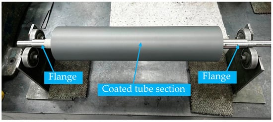
Figure 1.
Anilox narrow web roller made from difficult-to-cut materials such as stainless steel. (Image courtesy of Sandon Global Engraving Technology Ltd.®, Runcorn, UK).
Chatter is a significant limitation that may cause premature tool failure, bad machined surface quality, and dimensional tolerance violations when processing the tube components by turning operations [2,3]. The established literature on the mechanisms of chatter [4] and their avoidance techniques [5,6] helped to model and mitigate the chatter vibrations when machining flexible workpieces as well as tube or hollow cylindrical components.
Recent modeling of tube structures uses the analytical beam models, finite element modeling, or experimental modal analysis (i.e., impact hammer testing) approach to first identify the complex mode shapes of each vibration mode [7,8]. Then, stability lobes diagram (SLD) can be simulated by numerical or analytical methods to decide on the spindle speed and depth of cut pairs that would achieve stable cuts for a given flexible tool/workpiece system [4]. However, due to very high structural flexibility, the productivity may be too low since a stable cut can only be achieved at a very small depth of cut. Also, requiring multiple passes would increase the cycle times and reduce the economic feasibility of using turning operations. Alternatively, the stable depth of cut can be increased by modifying the system either actively (based on process signals) or passively [5]. An established passive way is to add a tuned mass damper (TMD) that absorbs the excessive vibrations on either the tool or workpiece. However, recently, using supporting materials has shown to be quite effective in suppressing vibrations for thin-walled components.
Following the vibration solution by Kolluru et al. for thin-walled casings [9], Khoshdarregi and Altintas [10] attempted to resolve the vibration problem in thread turning of cylindrical shell-type components by using a rubber strip with spring supports and they reported a reduction of over 15 times in machining vibrations. However, putting a rubber strip at the internal surface may not be practical if the reach to inside the component is limited or if the component would go under temperature-loading processes such as thermal shrink-fit or thermal spray coating processes that are, e.g., typical for Anilox rollers (see Figure 1). Using a steady support (fixed or moving) is a commercial solution for mitigating vibrations in turning but it may damage the outer surface of the component and shorten its service life. Moreover, adding a rigid contact support may deform the tube material and introduce unwanted dimensional errors. As a modern variant of steady support, Ozturk et al. applied soft rolling support by an assistive robot and achieved a 60% decrease in form errors [11]. The method is very promising for providing support to rotating parts, but the required dedicated programming and full integration of a robot may limit its use in practice. Recently, Liu et al. used ice to reinforce the flexible cylindrical workpiece during machining and reduced the maximum deformation by 63% [12]. Although ice provides softer support, it needs a thermally stable system and would be challenging to apply for rotating workpieces. Therefore, using viscous fluids could be a cost-effective alternative by providing soft and distributed support.
Viscous fluids are key to providing additional damping for the boring bars with tunable natural frequency and damping ratio; apart from the effect of the tuned mass and stiffness, viscous fluids inside such boring bars help achieve a three-fold increase in productivity [13]. In fact, boring bars are a variant of the Lanchester damper that was patented in 1914 [14]. Although its nonlinear dynamics and sealing requirements are concerns for the design, Lanchester dampers have proven to be quite effective for mitigating vibrations in rotating systems [15]. For milling, the concept of mitigating the machining vibrations by submerging flexible workpieces completely in silicone oil was coined by the authors of [16]. They also reported a 10+ times increase in the stability limit when milling thin-walled workpieces [17]. Alternatively, in pocket milling, flexible workpiece vibrations could be damped by filling the pockets with silicone oil [18]. Although there have been quite a few related studies for mitigating milling and boring bar vibrations, the use of viscous fluids has not been tried for mitigating vibrations for the thin-walled turning process.
In this study, for the first time, a novel solution based on the Lanchester damper concept by using viscous fluid is proposed to mitigate the machining vibrations for turning the flexible tube-like cylindrical components. The next section (Section 2) will introduce the method and experimental setup, Section 3 introduces the results, and Section 4 will conclude the paper.
2. Methodology
2.1. Lanchester Damper-like Workpieces
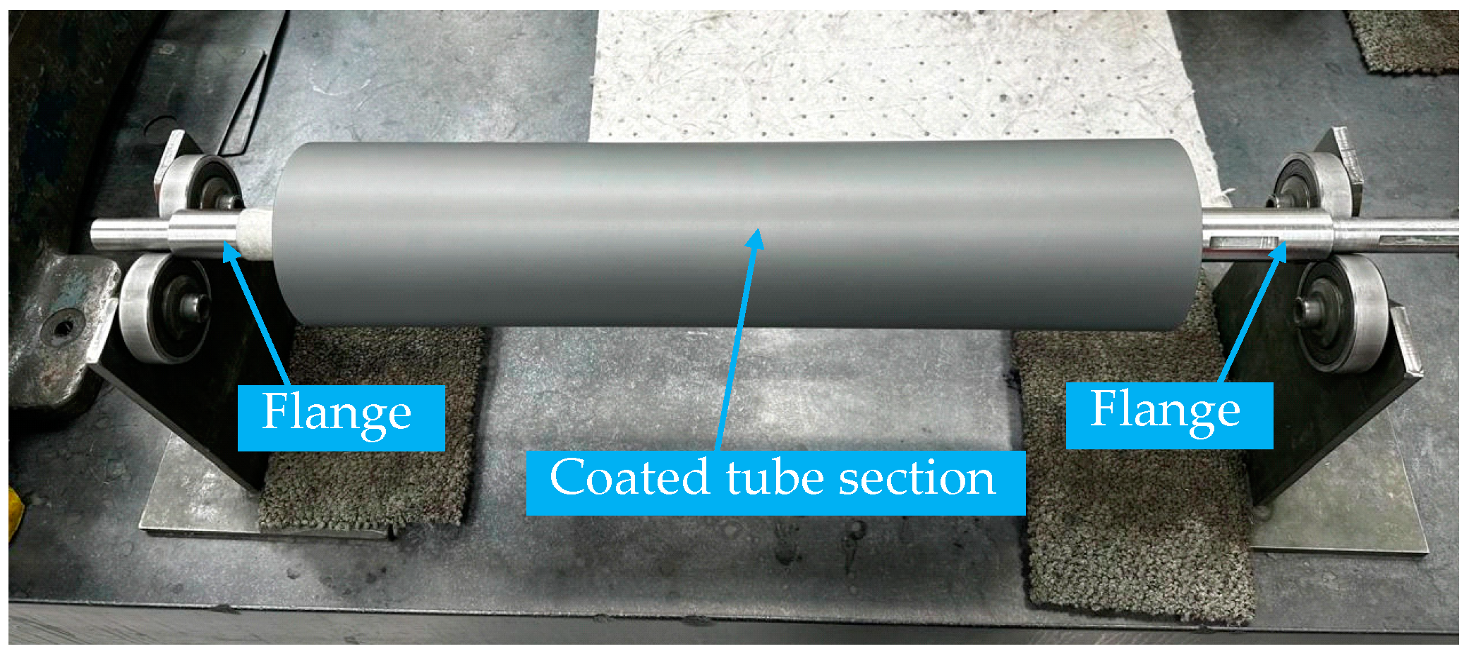
Three identical cylindrical workpieces of Aluminum 6082 were manufactured for the investigation; Figure 2 shows the main elements of each Lanchester damper-like workpiece. As shown in Figure 2, each workpiece is formed by welding a thick slab at each open end of a 320 mm long tube with a 70 mm nominal outer diameter and 3 mm thickness. The slabs seal the ends of the tube to keep the viscous fluid inside the tube. One of the slabs has a tapped hole which was sealed using a tapered hexagonal plug after filling up the workpiece with damping oil.
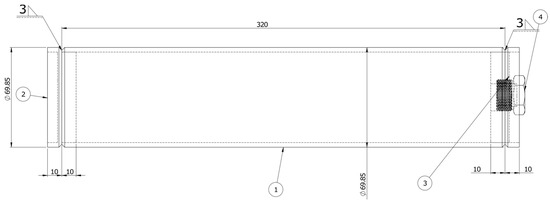
Figure 2.
Assembly drawing of the Lanchester damper-like workpiece: (1) Round Aluminum tube with 3 mm wall thickness, (2) welded end slab without tapped hole, (3) welded end slab with tapped hole to allow filling the workpiece with oil, (4) hexagonal head plug. All dimensions are in mm.
The Lanchester damper-like workpieces investigated in this paper are filled with viscous fluids having different viscosities. One of the workpieces was left unfilled (reference condition) while the other two were filled completely with 1 L motor oil (102 cSt viscosity) and 1 L silicone oil (350 cSt viscosity), respectively. The tapped holes (used for filling the tubes) were closed using tapered plugs wrapped with Polytetrafluoroethylene (PTFE) tape to ensure proper sealing.
2.2. Modal Analysis of the Components
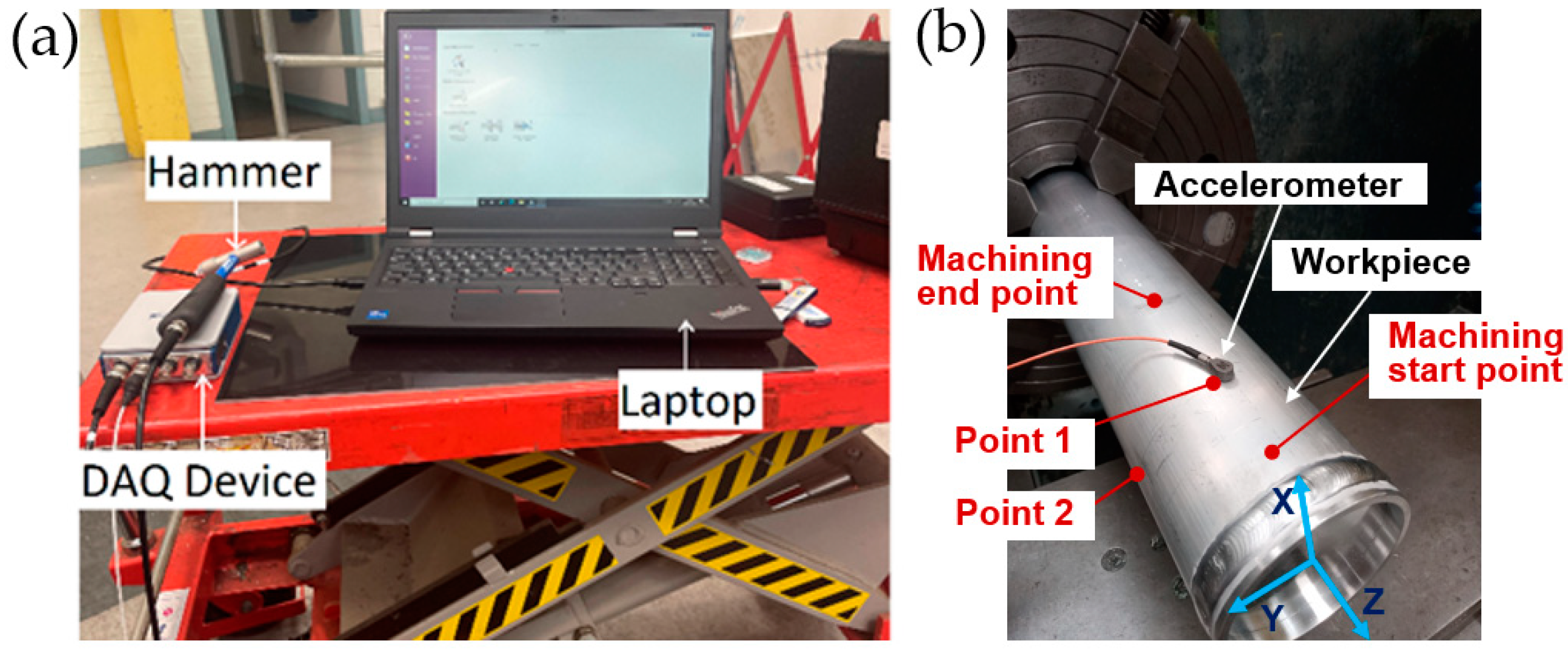
The unfilled tube was tap-tested to identify its modal parameters and decide on the machining conditions for the experiments. As shown in Figure 3, a standard tap testing setup with a modal hammer (Dytran 5800B4, Dytran Instruments, Inc., Chatsworth, CA, USA), a single-axis accelerometer (Dytran 3225F1, Dytran Instruments, Inc., Chatsworth, CA, USA), and a data acquisition (DAQ) device (NI-9234 C series, National Instruments Corp., Austin, TX, USA) were used along with CUTPRO® (MAL Inc., Vancouver, BC, Canada) software (version 16.0.1338.1) [19] (installed on a laptop PC) that calculates the Frequency Response Function (FRF) of the workpiece structure. After installing the workpiece on a manual lathe machine, the accelerometer was placed on the workpiece at a 60 mm distance from the free end to conduct the tap testing. As shown in Figure 3b, the location is in the middle of the machined section to be able to predict the average limit depth of cut for stability. Also, the accelerometer measures the vibrations in a positive radial X direction.
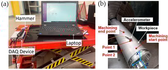
Figure 3.
Experimental setup of impact hammer testing: (a) Data collection and analysis, (b) Measurement setup on the workpiece.
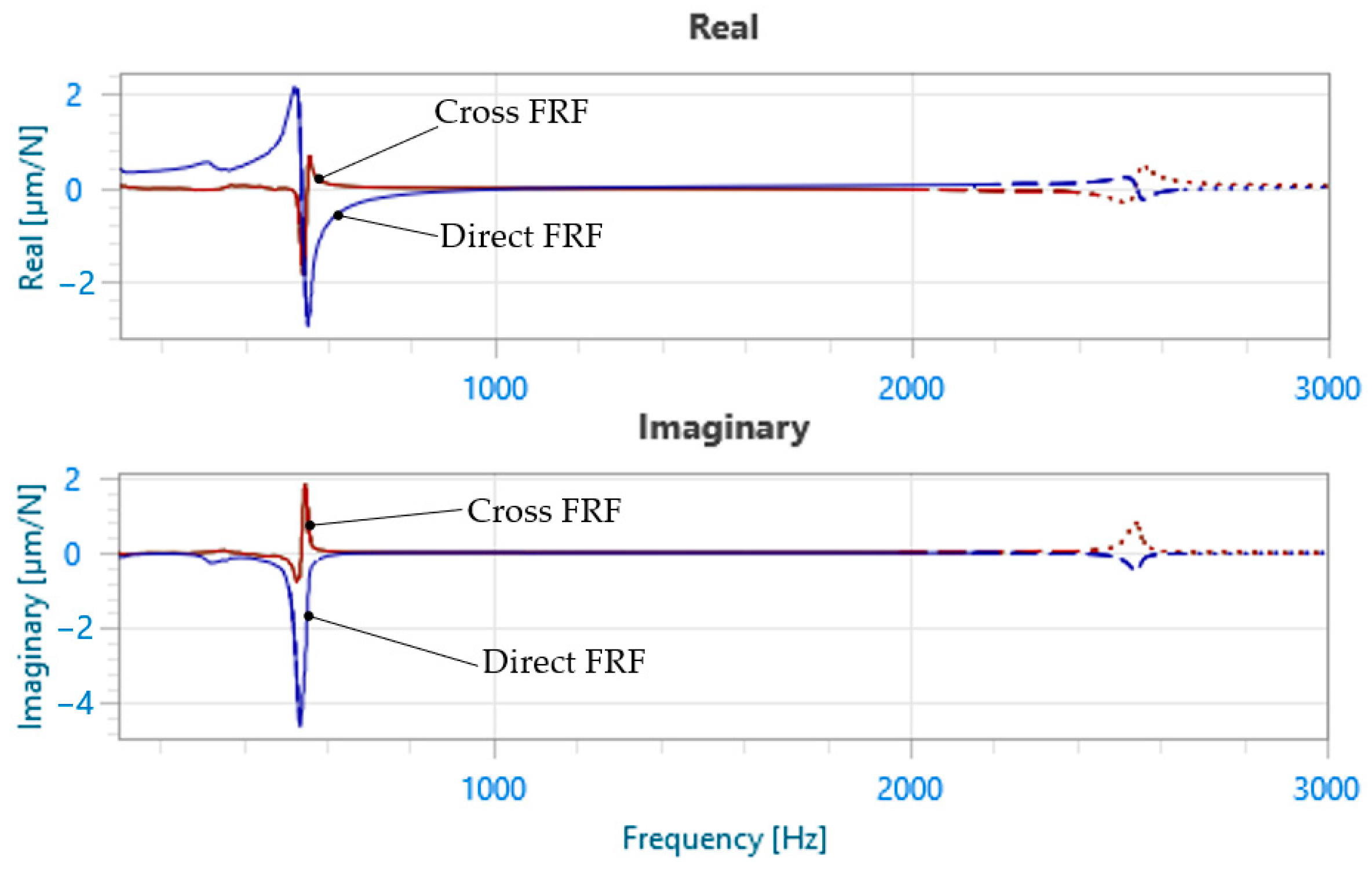
The experimental procedure involved tapping the hammer against the workpiece at two locations with the accelerometer being at the fixed location, which is close to the free end to ensure capturing the mode shapes of all possible vibration modes. Both direct (hit just next to the accelerometer location in negative radial X direction) and cross (hit in negative radial Y direction) tap testing measurements were conducted to identify modal parameters of the workpiece under clamped-free boundary conditions. The measured FRFs are shown in Figure 4. Then, CUTPRO® was used to predict the stability lobes diagram (SLD) using the measured direct (radial X−radial X) and cross (radial X−radial Y) FRFs of the workpiece at the accelerometer location [19]. The predicted SLD is given in Figure 5.
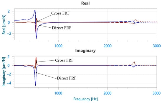
Figure 4.
Direct FRF (radial X−radial X) and cross FRF (radial X−radial Y) from the tap testing of the unfilled tube. (From experimental modal analysis: The natural frequencies at ~500 Hz and ~2500 Hz are identified as they belong to the first bending and first shell vibration modes, respectively).
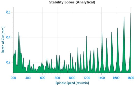
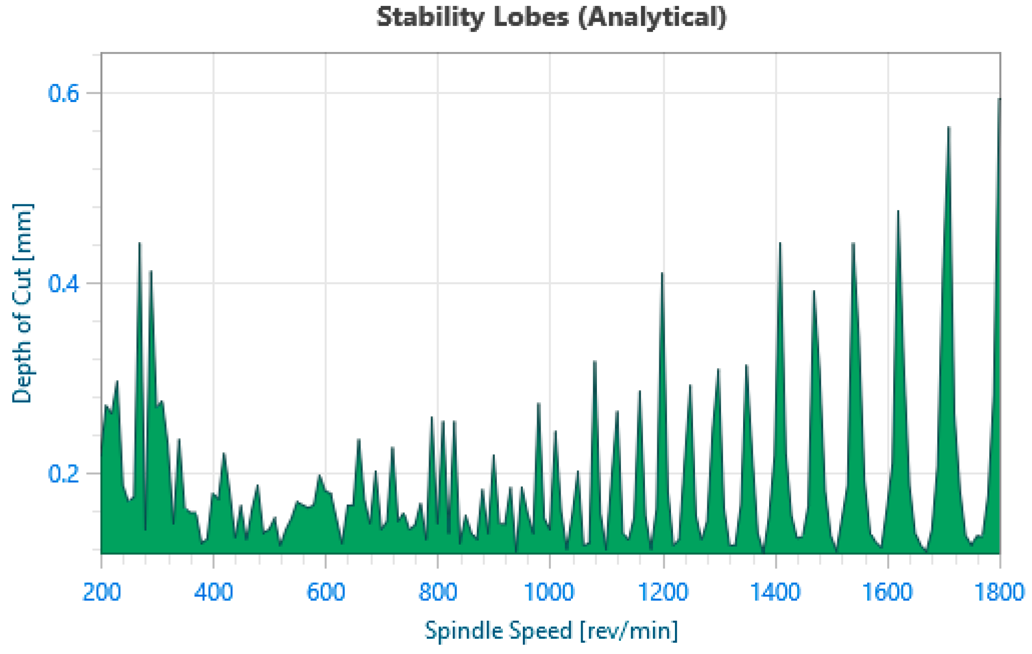
Figure 5.
Predicted stability lobes diagram (SLD) for machining the unfilled tube.
2.3. Turning Experiments
Cylindrical turning experiments were carried out at the cutting conditions which were selected according to the predicted SLD for the unfilled tube (see Figure 5). The spindle speed was set at 1600 rev/min considering the maximum allowed spindle speed of the lathe machine. In turning metal components with regular damping, the stability pockets are too narrow because of the low-speed range that the machines can achieve. For example, with the first dominant natural frequency being around 500 Hz (see Figure 4), the chosen 1600 rpm spindle speed coincides with about the 19th stability pocket since about 19 natural vibration periods (1/500 = 0.002 s) would occur in every spindle revolution period (60/1600 = 0.037 s), i.e., since 0.037/0.002 equals 19. As a result, at low spindle speeds, the cutting velocity may introduce additional process damping due to the combined indentation and rubbing of the insert’s flank face on the workpiece [20]. Moreover, as can be seen in the SLD (Figure 5), the pocket just next to the 1600 rpm has a width of about 40 rpm which is very narrow and not feasible for machining. Therefore, the choice of spindle speed is not expected to affect the stability characteristics in this region.
The axial depth of cut was then selected based on the SLD obtained from the measured FRFs. Based on the predicted SLD in Figure 5, the axial depth of cut is set as 0.5 mm which is well above the limit depth of cut for speeds below 1700 rev/min. Recalling that the FRFs were measured at the midpoint of the section to be machined, machining of the unfilled tube is expected to be under chatter along the whole machined section. It is intentional to have chatter conditions for the unfilled tube to prove the effectiveness of using viscous fluids for chatter mitigation. The cutting conditions along with the tool specifications are given in Table 1.

Table 1.
Experiment conditions for the cylindrical turning operation.
For these tests, the workpieces, i.e., the unfilled tube, tube filled with motor oil, and tube filled with silicone oil were all machined for a total length of ~110 mm (Lmachining) from the weld line at the free end. Figure 6 shows the schematics of the experimental setup used for the investigation. Each workpiece was clamped at the side that had the tapped plug (i.e., the right side of the workpiece shown in Figure 2). Moreover, the clamping length was 50 mm and the clamp contact started at a 25 mm distance from the end with the plug. Thus, the overhang length was 265 mm. The side without the plug was set as the free end to avoid the risk of the hexagonal head plug being airborne during machining. The cutting insert was engaged at a 25 mm (Ls) distance from the free end to avoid machining the welded section.

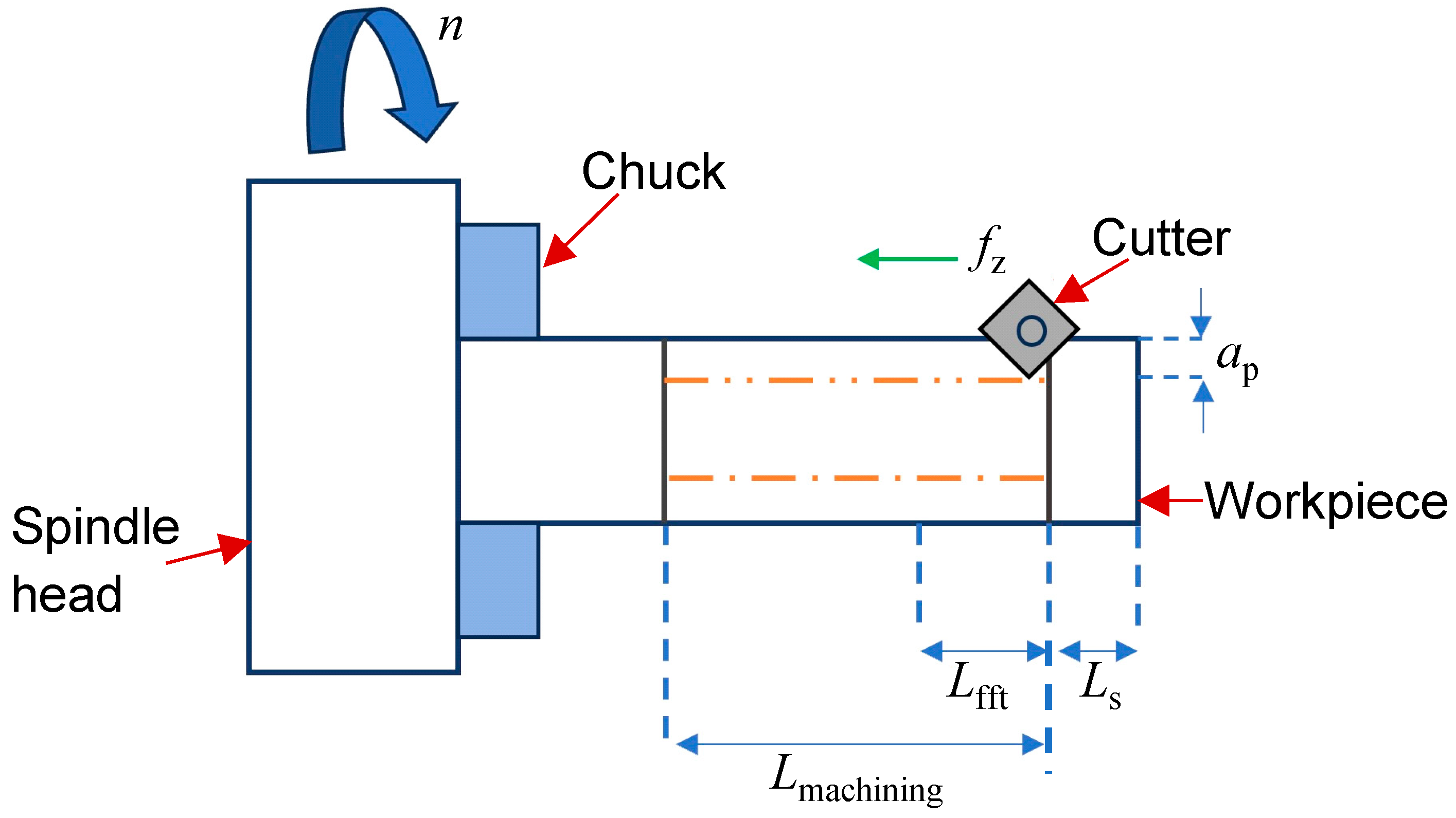
Figure 6.
Schematics of the turning operation (where Lmachining denotes the total machining length, Lfft is the length over which FFT is calculated, and Ls is the machining starting distance).
The machining process sound pressure was measured with a Shure SM-137 professional instrument condenser microphone (Shure, Inc., IL, USA) and the data were gathered at 51.2 kHz by the NI-9234 C series (National Instruments Corp., TX, USA) data acquisition (DAQ) module. The amplitude of the Fast Fourier Transforms (FFTs) for each sound pressure dataset was analyzed during the first 5 s of the machining process, corresponding to ~17 mm cutting length (Lfft) where the workpiece had the highest flexibility hence the least chatter-resistance along the entry section.
The microphone is a cardioid type; hence, it has an almost uniform response over the 180-degree field in front of it and with minimal response to any sound generated behind it. Therefore, to have an effective measurement, the positioning of the microphone must be such that it is aimed at the machining area. Moreover, considering the safety aspects, it is fixed on the tailstock to provide a safe distance from the cutting location while keeping an acceptable distance to record the machining sound properly. The location of the microphone in the experiment setup can be seen in Figure 7.
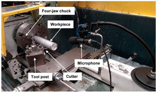
Figure 7.
Sound measurement setup for the machining tests.
Surface roughness tester Surtronic Duo (Taylor Hobson Ltd., Leicester, UK) was used to measure the surface roughness parameters such as average roughness (Ra) and mean roughness depth (Rz) of the machined surfaces.
3. Results
3.1. Machining Process Vibration
The graphical plots of the FFTs of the measured sound pressure when machining the most flexible section (see Lfft in Figure 6) of the unfilled tube, tube full of motor oil, and tube full of silicone oil) are presented in Figure 8.
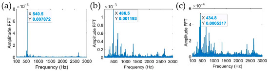
Figure 8.
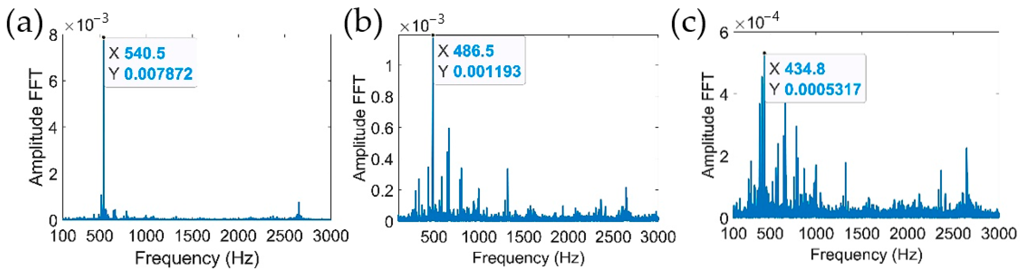
FFTs of the measured sound pressure when machining in the region 1 (R-1): (a) unfilled tube (chatter); (b) tube filled with motor oil (marginal chatter); (c) tube filled with silicone oil (stable).
It was found that the measured sound pressure levels were significantly less for the tube filled with the most viscous fluid, which was silicone oil followed by motor oil. The sound pressure levels when machining the unfilled tube indicate chatter vibrations with the dominant vibration frequency close to the natural frequency of the first bending mode of the workpiece under clamp-free conditions. As can be seen from Figure 8a,b, the FFT amplitude of the dominant vibration mode (close to 500 Hz) was decreased by 6.6 times when the tube was filled with motor oil before machining. In the case of the tube filled with silicone oil, as seen in Figure 8c, the FFT amplitude of the dominant vibration frequency at 434.8 Hz was 14.8 times smaller when compared to the amplitude of the chatter vibrations when machining the unfilled tube. Moreover, the tube filled with silicone oil no longer showed a clear dominant frequency as compared to the other two cases (Figure 8a,b), indicating that the process was stable.
For a fixed stiffness, a reduction of the natural frequency is expected due to the mass effects of the added oil. For example, silicone oil has an average density of 1040 kg/m3, and motor oil’s average density is 825 kg/m3. Therefore, since the vibration mode around 500 Hz is linked to the first bending mode, one would expect that the equivalent mass will affect the natural frequency by the square root of the amount of increase. Thus, for a comparison of natural frequencies of the two components with the same volumes of motor and silicone oils inside, a decrease would be expected at their density ratio, i.e., sqrt (1040/825) = 1.122, which indeed is the same as the ratio of the measured dominant frequencies, i.e., 486.5/434.8 = 1.118.
3.2. Surface Quality
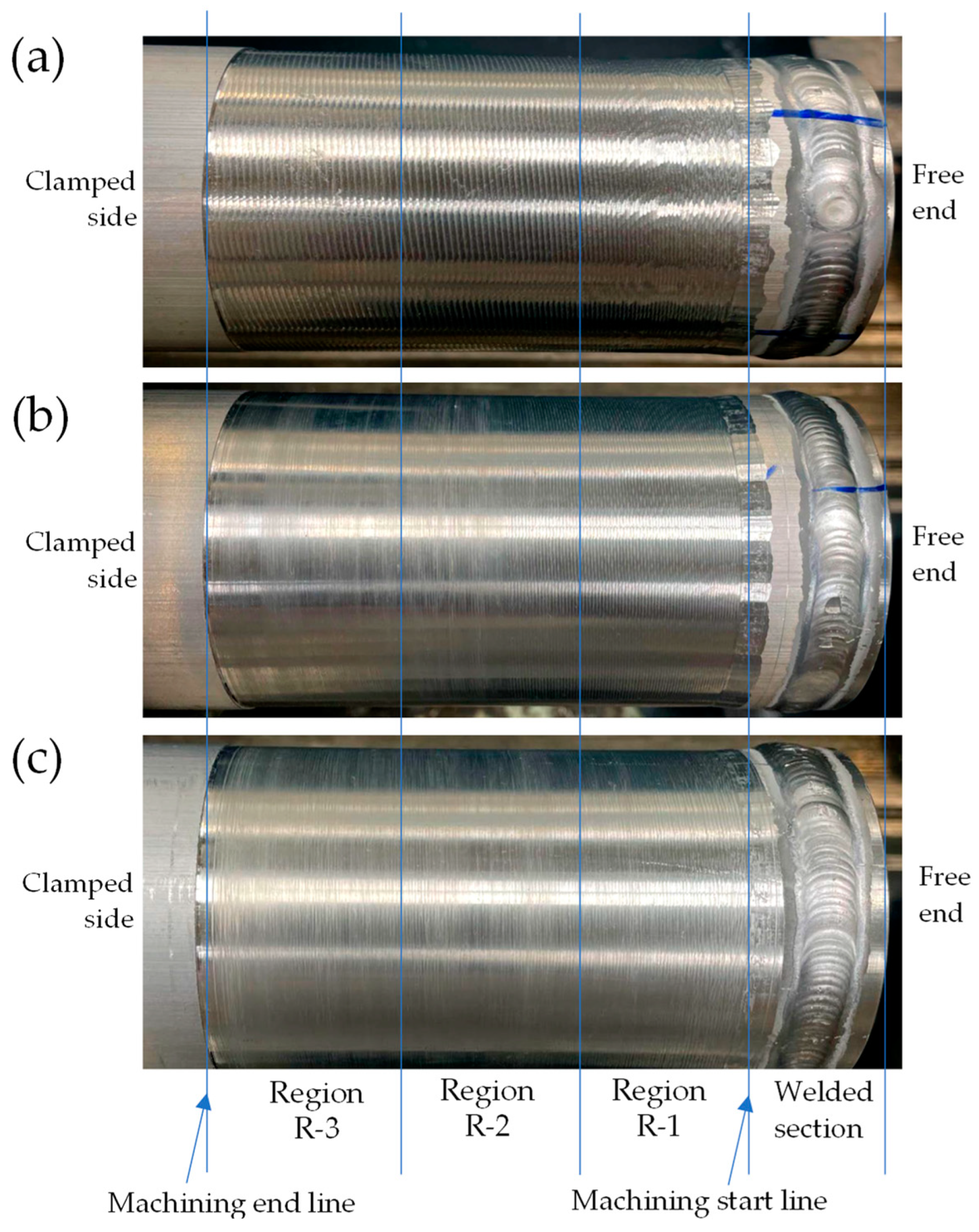
Average surface roughness (Ra) and mean surface roughness depth (Rz) were measured at three sections along the machining length on each tube as shown in Figure 9, i.e., near the free end (Region 1, or R-1), midsection (Region 2, or R-2), and on the clamped end side (Region 3, or R-3). The roughness parameter values for Regions 1, 2, and 3 for the test workpieces are presented in Table 2. The unfilled tube has the highest values of surface roughness across all regions, clearly showing the effects of excessive vibrations around R-1 and R-2. The averaged arithmetic values of Ra and Rz across all regions of the tube filled with motor oil were lower by 47% and 46%, respectively, when compared to the unfilled tube. For the tube filled with silicone oil, similar relative values were significantly lower by 50.3% and 45.2% for the tube filled with silicone oil. The findings can also be confirmed by visually examining the surface quality of the machined tubes which are displayed in Figure 9.

Figure 9.
Machined surface of each workpiece with the three measured regions shown: (a) the unfilled tube has visible vibration marks all along the workpiece and chatter marks in region R-1; (b) the tube filled with motor oil has mild vibration marks close to the free end in region R-1; (c) the tube filled with silicone oil has negligible vibration marks close to its free end.
Table 2.
Surface roughness values of the machined workpieces in three regions, i.e., R-1, R-2, and R-3—see Figure 9. (“Avg.” column indicates the “Average value across all regions”).
For the tubes filled with viscous fluids, i.e., motor oil and silicone oil, the surface roughness values are higher at the start of machining (i.e., in R-1) due to higher flexibility at the free end and they reduce toward R-3 as the workpiece stiffness increases. Additionally, at the entry region R-1, the tube filled with silicone oil exhibited a 22% and 20% reduction in Ra and Rz when compared to the values from the tube filled with motor oil. Hence, in parallel with the findings from the vibration signal, improved stability and better damping effects were observed for the fluid with higher viscosity.
4. Discussion on the Stability and Roughness Improvements
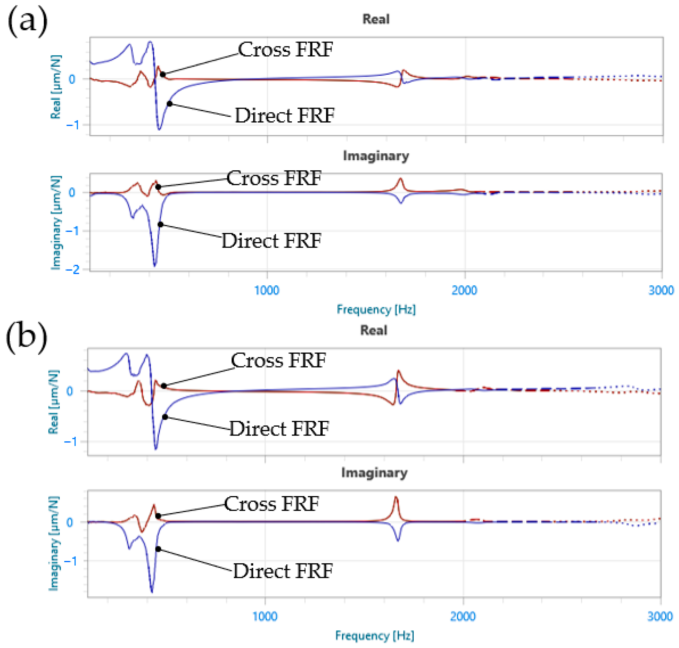
Figure 10 shows the measured FRF plots for the tubes filled with oil, and the identified modal parameters from the FRF tests of the three workpieces are given in Table 3. By modifying Tlusty’s stability formulation in Section 4.2.1 of [20], the following relation can be obtained to show that the absolute minimum stability limit would increase with the decrease in the minimum real parts of direct and cross FRFs, and :
where and are equivalent cutting force coefficients in X and Y directions, modified by tool geometry.
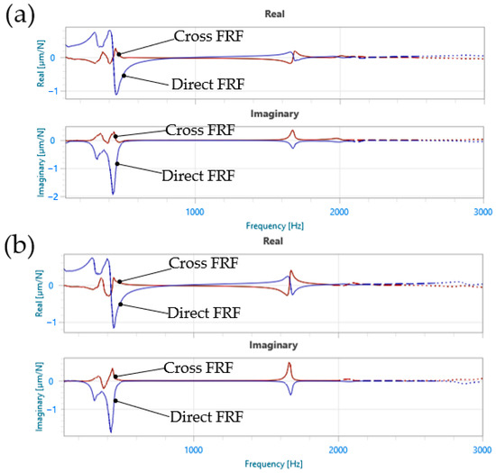
Figure 10.
Measured frequency response functions (FRF) of the tubes filled with motor oil (a) and silicone oil (b). FRF of the unfilled tube is given in Figure 4.
Table 3.
Identified modal parameters of the unfilled tube, and the tubes filled with motor and silicone oils. Modal analysis is conducted at the location shown in Figure 3b, under static conditions. For each vibration mode, and ζ are the natural frequency and damping ratio, while the mass normalized mode shape vector U has the displacement components in X and Y directions.
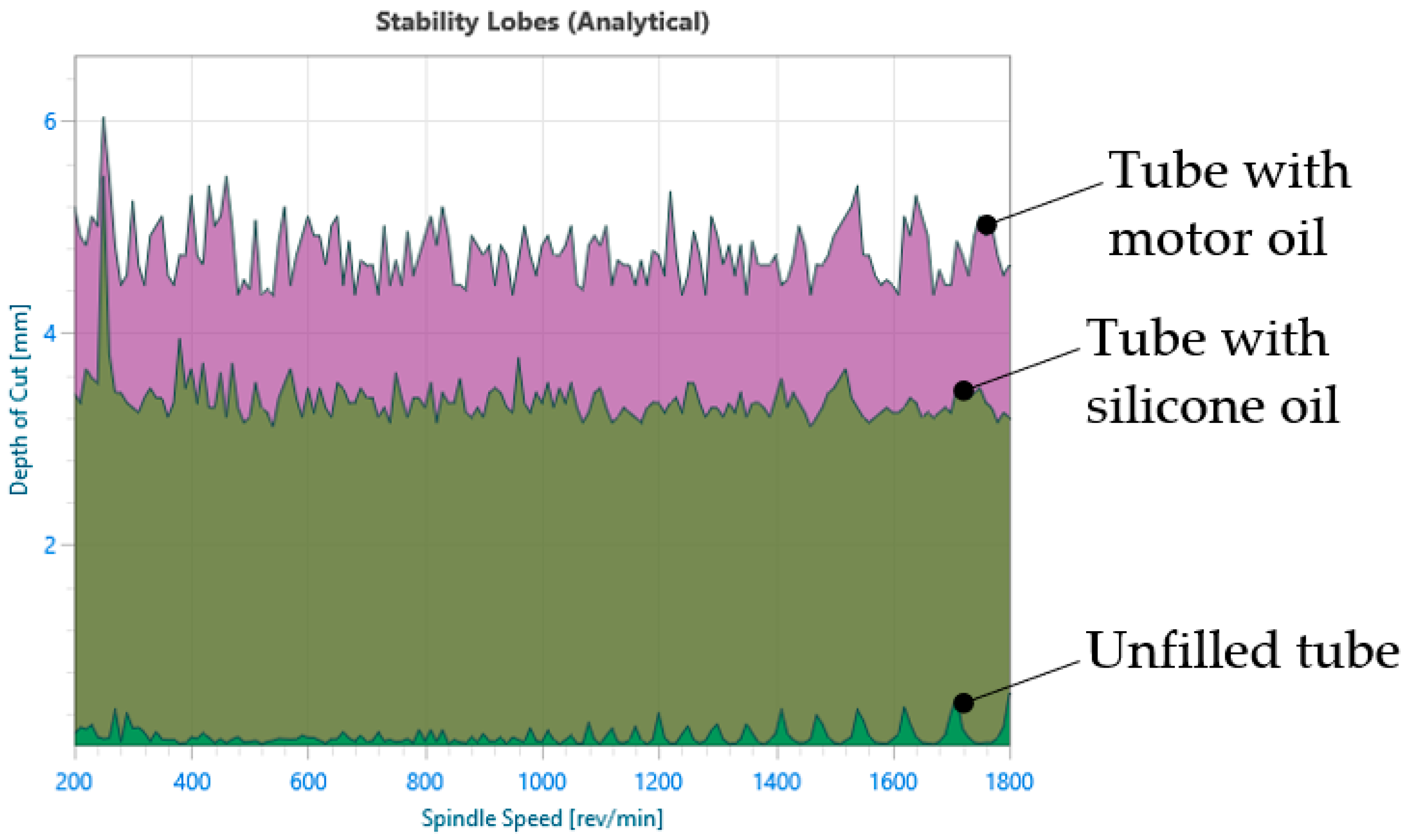
Comparing the original FRF in Figure 4 and the FRFs of filled workpieces in Figure 10 shows that adding viscous fluid to the tubes increase the damping ratio of the dominant vibration mode (i.e., Mode 2 in Table 3) and decrease the peak magnitude of the cross FRFs. Therefore, from Equation (1), it is expected that the absolute minimum limit would shift to higher values. Figure 11 shows a comparison between the unfilled and filled tubes to verify this increase.
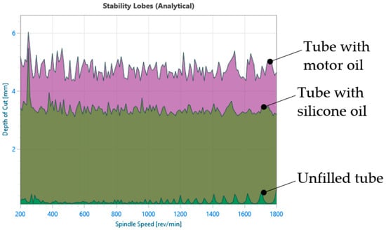
Figure 11.
Comparison of the predicted stability lobes diagrams (SLDs) of the unfilled tube with the tubes filled with motor oil and silicone oil.
The roughness values presented in Table 2 are the average of three measurements made on each R-1, R-2 and R-3 region. As explained by Armarego [21], the combined effect of feed rate and tool nose radius would leave cusps or extra material on the machined surface. For feed rate and tool nose radius , the maximum surface roughness can then be predicted as follows:
Moreover, the average surface roughness can be determined as follows [22]:
With mm/rev and mm, the and can be predicted from Equation (3) as micrometer and micrometer. The findings in the previous literature indicate that the is usually underpredicted with up to two times difference with measured results [23], and with the expected ratio being as high as seven times [24]. Therefore, the predicted and values for tubes filled with oil can be considered quite close to the measured values in R-3 region, indicating that the roughness would be related to the feed marks rather than chatter vibrations. Furthermore, Regions R-2 and R-3 of the filled tubes have better stability than the unfilled tube, while much less improvement is seen in Region R-1.
In Table 2, the measured roughness in Region R-2 may show that tube with silicone oil is more prone to vibrations than the tube with motor oil. Indeed, the SLD in Figure 11 also suggest that the tube with motor oil may have better stability. However, this would need more controlled tests as the roughness may also depend on tool wear Therefore, further work is required to investigate whether this effect is due to mass or damping of the added fluid, and if the volume, density, and viscosity of the added fluid could be tuned according to workpiece dynamics.
5. Conclusions
The effectiveness of using viscous fluids to eliminate chatter when turning a flexible cylindrical component was experimentally validated by investigating the machining process vibrations and machined surface quality of a tube. Two viscous fluids, i.e., motor oil and silicone oil, were used as a filler inside two tubes, and the results were compared with the unfilled (empty) tube. The filled tubes resulted in improved machining vibrations, and the results indicate that an increase in fluid viscosity would improve the damping performance. When compared to turning the unfilled tube, the magnitude of the dominant (chatter) frequency was reduced by 6.6 times when turning the tube filled with motor oil, and by 14.8 times when turning the tube filled with silicone oil that is 3+ times more viscous than the motor oil. The performance improvement was also verified by the surface roughness analysis; clear chatter marks could be seen on the empty tube, and the tubes with motor oil and silicone oil had a better surface finish with no chatter marks.
Although the proposed passive damping method was validated for a tube-like workpiece made from Al6082 alloy, the concept is applicable to machining difficult-to-cut materials such as stainless steel and Ti64 alloys. In the case of Anilox roller production, the proposed method has a high potential to reduce costs, machining times, and surface quality. As this is the first study that investigate the novel proposed solution, more investigations are required to further understand the underlying mechanisms. Hence, the following are possible future research directions to improve the proposed solution:
- -
- The models simulating the stability of turning flexible tubes need to be extended to include the complex mechanics and dynamics of a Lanchester damper, i.e., cylinder-like structures rotating with a viscous fluid inside. Additionally, detailed modal analysis is required to understand and tune the effects of fluid on the mass and damping characteristics of the tube in both radial directions. New design methods to implement the proposed concept on already existing components and machinery need to be developed.
- -
- The spindle speed can be further optimized through dedicated tests to achieve better surface roughness in Region R-1, by considering the spindle speed-dependent stability and vibrations. Also, the process damping effects on the stability at low cutting speeds could be modeled for harder, difficult-to-cut metals, which are also common materials for Anilox rollers.
Author Contributions
Conceptualization, M.G. and Z.M.K.; methodology, M.G. and Z.M.K.; investigation, M.G. and Z.M.K.; data curation, M.G., Z.M.K., and V.K.; writing—original draft preparation, M.G.; writing—review and editing, Z.M.K. and V.K.; visualization, M.G., Z.M.K., and V.K.; supervision, Z.M.K. All authors have read and agreed to the published version of the manuscript.
Funding
The second author is a research associate of the Innovate UK KTP 13112 project, which is funded by UKRI Innovate UK and Sandon Global Engraving Technology Ltd.®.
Data Availability Statement
The data presented in this study are available upon request from the corresponding author.
Acknowledgments
The authors would like to acknowledge the support of the University of Manchester’s FSE Schuster Workshop Team (managed by Darren Shepherd) and MECD Workshop Team to help accomplish this work, and Paul English for welding the Aluminum tubes. This study’s goals were partially inspired by the Innovate UK KTP 13112 project in which the second and third authors are working together with the support of Sandon Global Engraving Technology Ltd.®.
Conflicts of Interest
The authors declare no conflicts of interest.
References
- Uekita, M.; Takaya, Y. On-Machine Dimensional Measurement of Large Parts by Compensating for Volumetric Errors of Machine Tools. Precis. Eng. 2016, 43, 200–210. [Google Scholar] [CrossRef]
- Taylor, F.W. On the Art of Cutting Metals—Chatter of the Tool. Trans. ASME 1907, 28, 179. [Google Scholar]
- Arnold, R.N. Chatter Patterns Formed on the Surface of Thin Cylindrical Tubes during Machining. J. Mech. Eng. Sci. 1961, 3, 7–14. [Google Scholar] [CrossRef]
- Altintas, Y.; Stepan, G.; Budak, E.; Schmitz, T.; Kilic, Z.M. Chatter Stability of Machining Operations. J. Manuf. Sci. Eng. Trans. ASME 2020, 142, 110801. [Google Scholar] [CrossRef]
- Munoa, J.; Beudaert, X.; Dombovari, Z.; Altintas, Y.; Budak, E.; Brecher, C.; Stepan, G. Chatter Suppression Techniques in Metal Cutting. CIRP Ann.-Manuf. Technol. 2016, 65, 785–808. [Google Scholar] [CrossRef]
- Sun, Y.; Zheng, M.; Jiang, S.; Zhan, D.; Wang, R. A State-of-the-Art Review on Chatter Stability in Machining Thin−Walled Parts. Machines 2023, 11, 359. [Google Scholar] [CrossRef]
- Khoshdarregi, M.R.; Altintas, Y. Dynamics of Multipoint Thread Turning—Part I: General Formulation. J. Manuf. Sci. Eng. Trans. ASME 2018, 140, 061003. [Google Scholar] [CrossRef]
- Wan, M.; Wang, H.-N.; Yang, Y. Dynamics of the Truncated Conical Thin-Wall Turning Process. J. Manuf. Process. 2023, 94, 49–62. [Google Scholar] [CrossRef]
- Kolluru, K.; Axinte, D.; Becker, A. A Solution for Minimising Vibrations in Milling of Thin Walled Casings by Applying Dampers to Workpiece Surface. CIRP Ann.-Manuf. Technol. 2013, 62, 415–418. [Google Scholar] [CrossRef]
- Khoshdarregi, M.R.; Altintas, Y. Dynamics of Multipoint Thread Turning—Part II: Application to Thin-Walled Oil Pipes. J. Manuf. Sci. Eng. 2018, 140, 041016. [Google Scholar] [CrossRef]
- Verl, A.; Valente, A.; Melkote, S.; Brecher, C.; Ozturk, E.; Tunc, L.T. Robots in Machining. CIRP Ann. 2019, 68, 799–822. [Google Scholar] [CrossRef]
- Liu, H.; Zeng, L.; Wang, C.; Han, L.; Li, P.; Wang, Y. Force-Induced Deformation Mechanism for Cylindrical Shell Thin-Walled Parts Milling With Ice Supporting: Modeling and Prediction. J. Manuf. Sci. Eng. 2024, 146, 041002. [Google Scholar] [CrossRef]
- van Zyl, D.; Altintas, Y.; Ostling, D. Parametric Design of Boring Bars with Adaptive Tuned Mass Dampers. CIRP J. Manuf. Sci. Technol. 2022, 38, 491–499. [Google Scholar] [CrossRef]
- Lanchester, F.W. Damping Torsional Vibrations in Crank-Shafts. U.S. Patent No. 1085443. 1914.
- Vakilinejad, M.; Grolet, A.; Thomas, O. A Comparison of Robustness and Performance of Linear and Nonlinear Lanchester Dampers. Nonlinear Dyn. 2020, 100, 269–287. [Google Scholar] [CrossRef]
- Zhang, Z.; Li, H.; Meng, G.; Ren, S. Milling Chatter Suppression in Viscous Fluid: A Feasibility Study. Int. J. Mach. Tools Manuf. 2017, 120, 20–26. [Google Scholar] [CrossRef]
- Zhang, Z.; Li, H.; Liu, X.; Zhang, W.; Meng, G. Chatter Mitigation for the Milling of Thin-Walled Workpiece. Int. J. Mech. Sci. 2018, 138–139, 262–271. [Google Scholar] [CrossRef]
- Dang, X.-B.; Wan, M.; Zhang, W.-H.; Yang, Y. Chatter Analysis and Mitigation of Milling of the Pocket-Shaped Thin-Walled Workpieces with Viscous Fluid. Int. J. Mech. Sci. 2021, 194, 106214. [Google Scholar] [CrossRef]
- Altintas, Y. Modeling Approaches and Software for Predicting the Performance of Milling Operations at MAL-UBC. Mach. Sci. Technol. 2000, 4, 445–478. [Google Scholar] [CrossRef]
- Altintas, Y. Manufacturing Automation: Metal Cutting Mechanics, Machine Tool Vibrations, and CNC Design, 2nd ed.; Cambridge University Press: Cambridge, UK, 2012; ISBN 978-1-107-00148-0. [Google Scholar]
- Armarego, E.J.A.; Brown, R.H. The Machining of Metals; Prentice-Hall: Hoboken, NJ, USA, 1969. [Google Scholar]
- Ståhl, J.E.; Schultheiss, F.; Hägglund, S. Analytical and Experimental Determination of the Ra Surface Roughness during Turning. Procedia Eng. 2011, 19, 349–356. [Google Scholar] [CrossRef]
- Fang, X.D.; Safi-Jahanshahi, H. A New Algorithm for Developing a Reference-Based Model for Predicting Surface Roughness in Finish Machining of Steels. Int. J. Prod. Res. 1997, 35, 179–199. [Google Scholar] [CrossRef]
- Palásti-Kovács, B.; Sipos, S.; Czifra, Á. Interpretation of “Rz = 4 × Ra” and Other Roughness Parameters in the Evaluation of Machined Surfaces. In Proceedings of the 13th International Conference on Tools, Beijing, China, 12–13 June 2012. [Google Scholar]


Disclaimer/Publisher’s Note: The statements, opinions and data contained in all publications are solely those of the individual author(s) and contributor(s) and not of MDPI and/or the editor(s). MDPI and/or the editor(s) disclaim responsibility for any injury to people or property resulting from any ideas, methods, instructions or products referred to in the content. |
© 2024 by the authors. Licensee MDPI, Basel, Switzerland. This article is an open access article distributed under the terms and conditions of the Creative Commons Attribution (CC BY) license (https://creativecommons.org/licenses/by/4.0/).