

A Workflow for the Compensation of Substrate Defects When Overprinting in Extrusion-Based Processes


Abstract
:1. Introduction
2. Materials and Methods
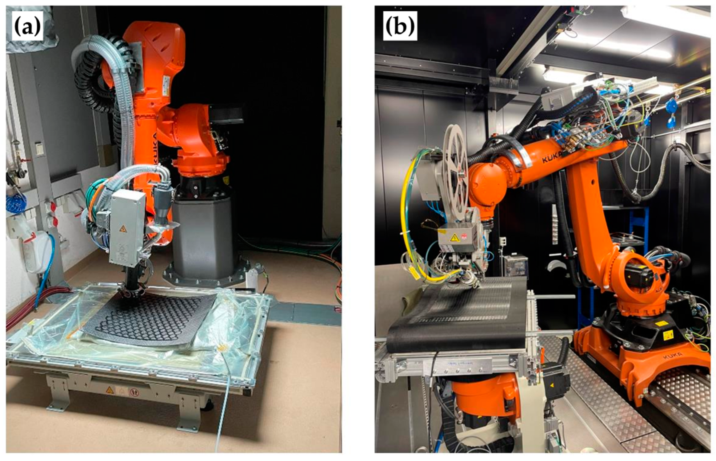
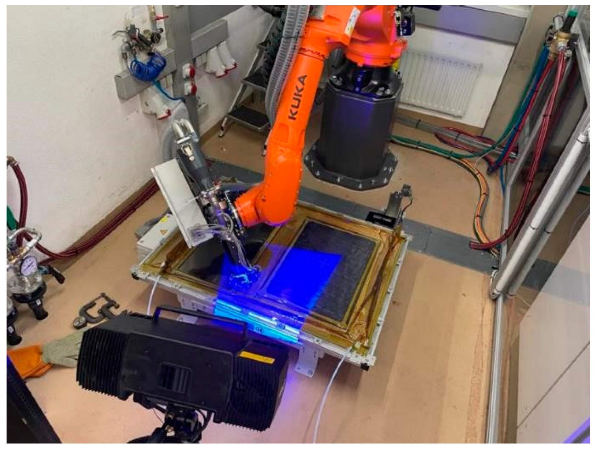
2.1. Manufacturing Facilities
2.2. Materials
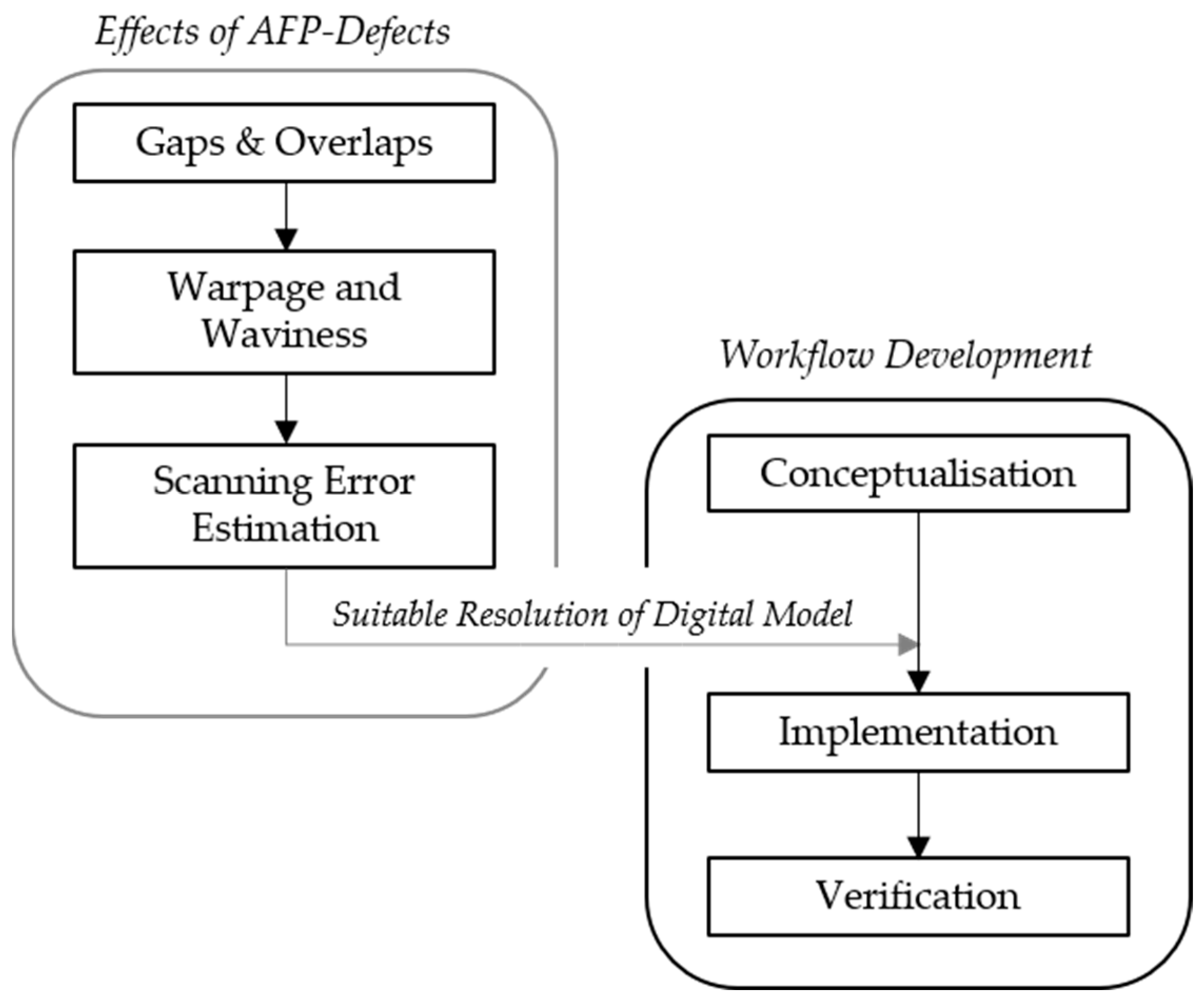
2.3. Methodology
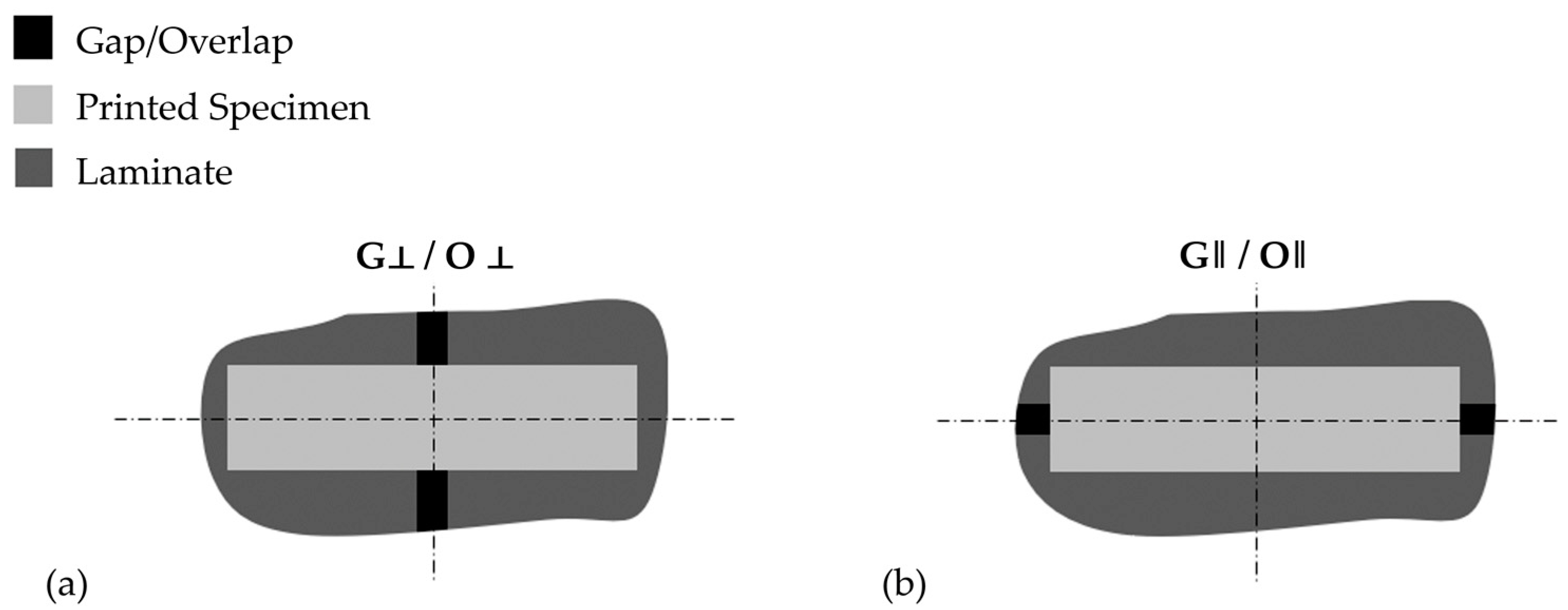
2.3.1. Determining the Effect of Defects
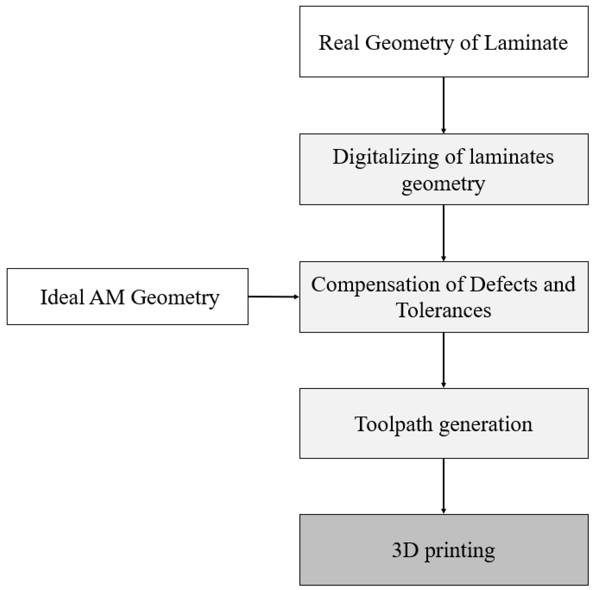
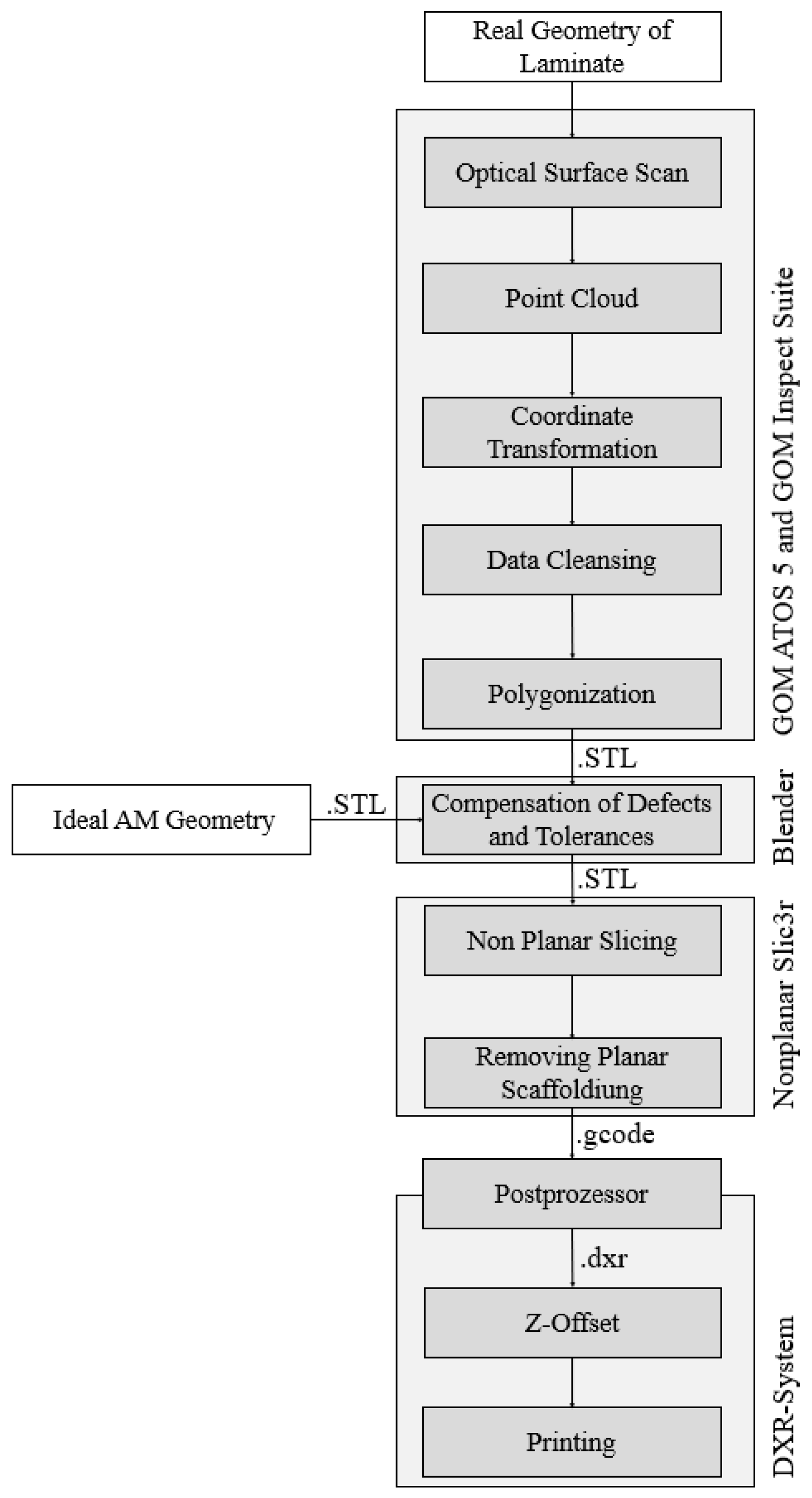
2.3.2. Workflow Implementation
2.4. Software
2.5. Testing and Statistics
3. Results
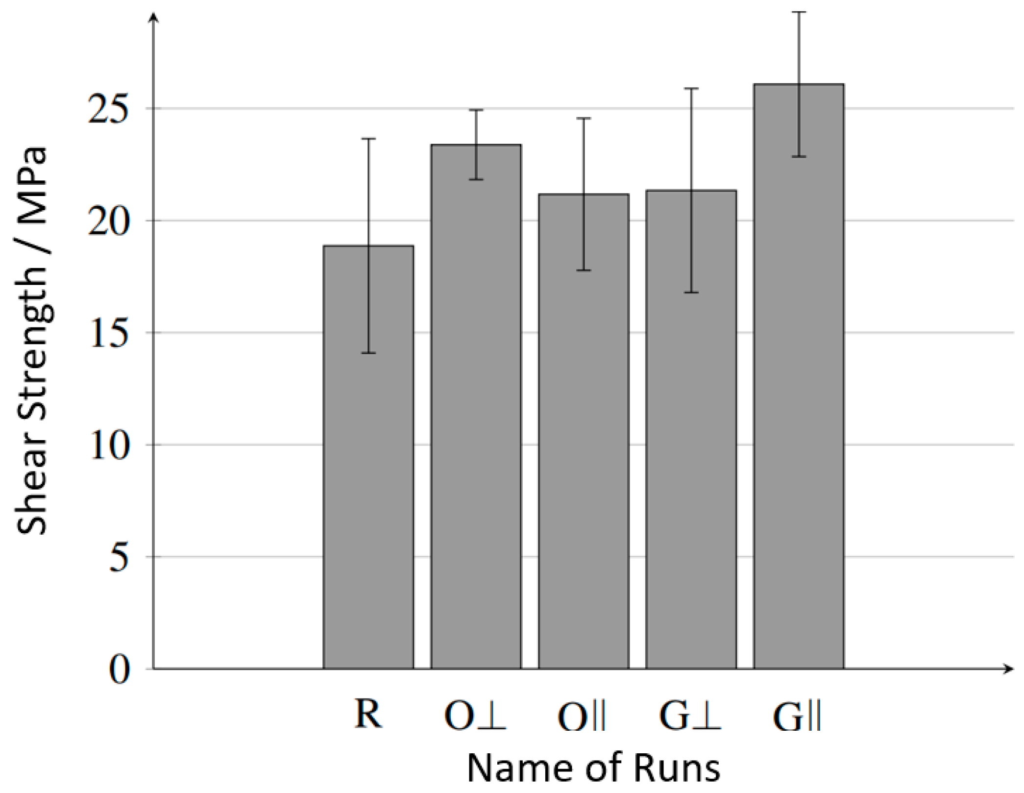
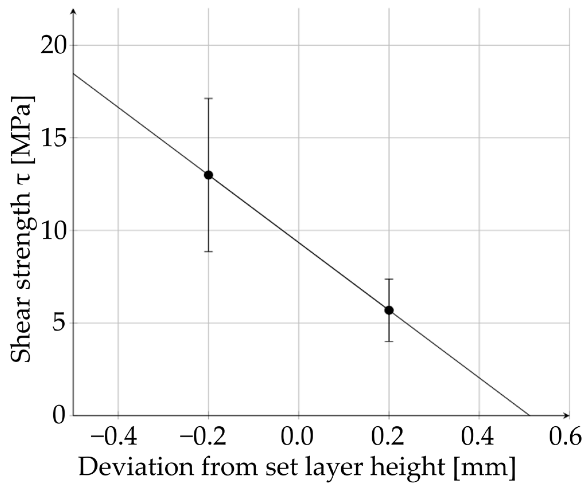
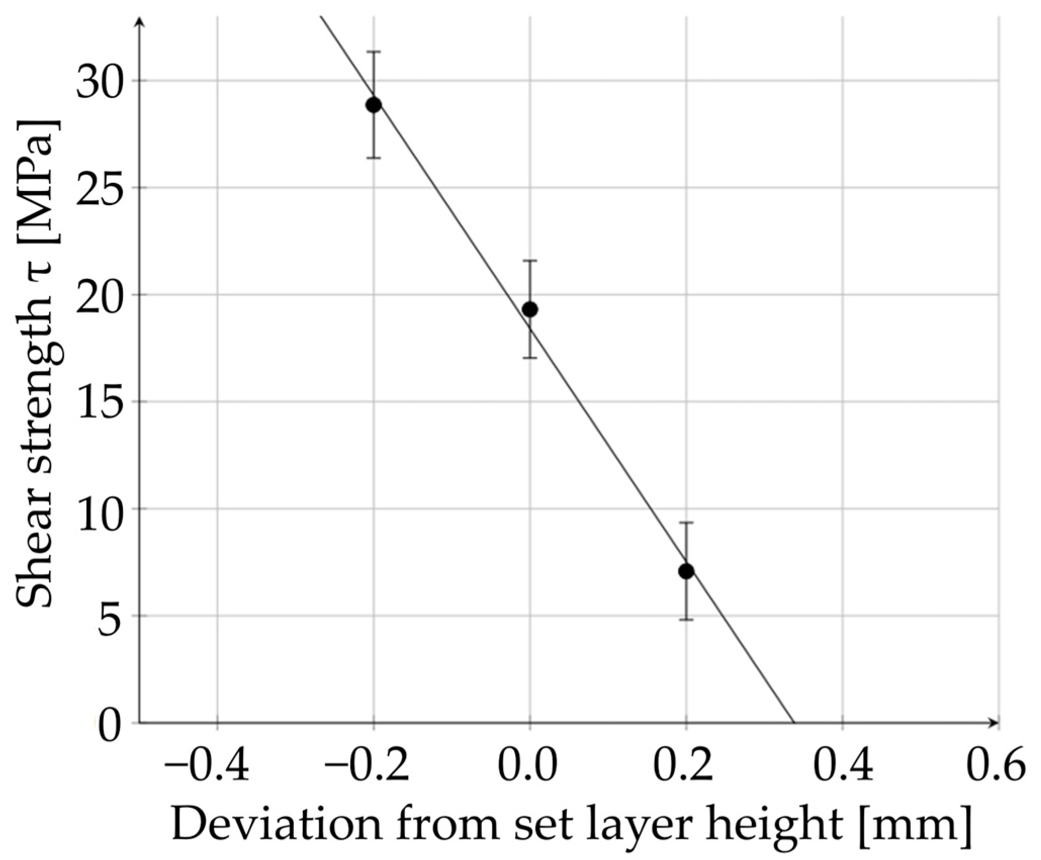
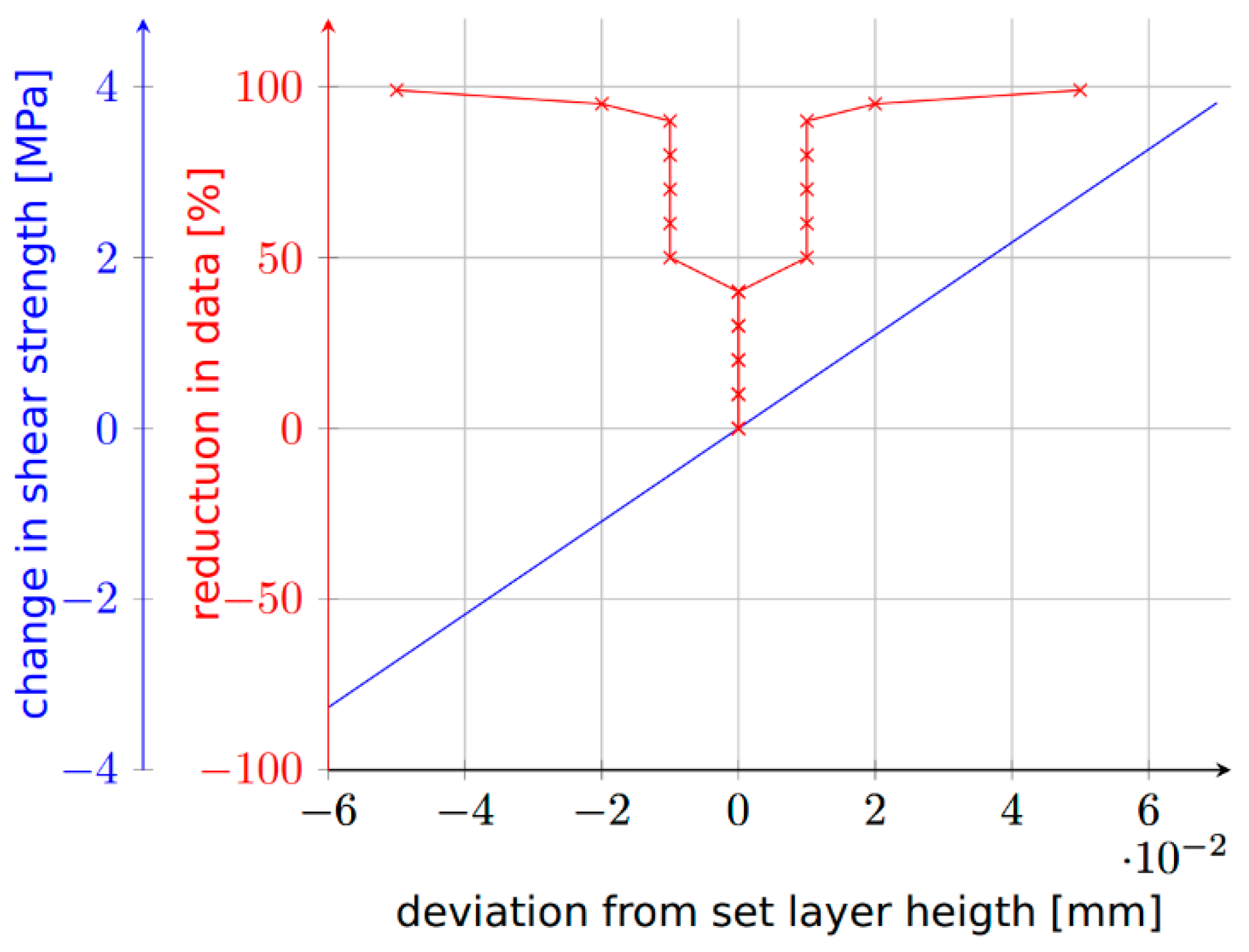
3.1. Effects of Defects
3.2. Process Flow to Account for Surface Defects
3.2.1. Conceptualizing the Process Chain
3.2.2. Testing the Process Flow
4. Discussion
5. Conclusions
- Global underextrusion due to excessive distance between the nozzle and the laminate in the order of the layer height leads to poor bonding;
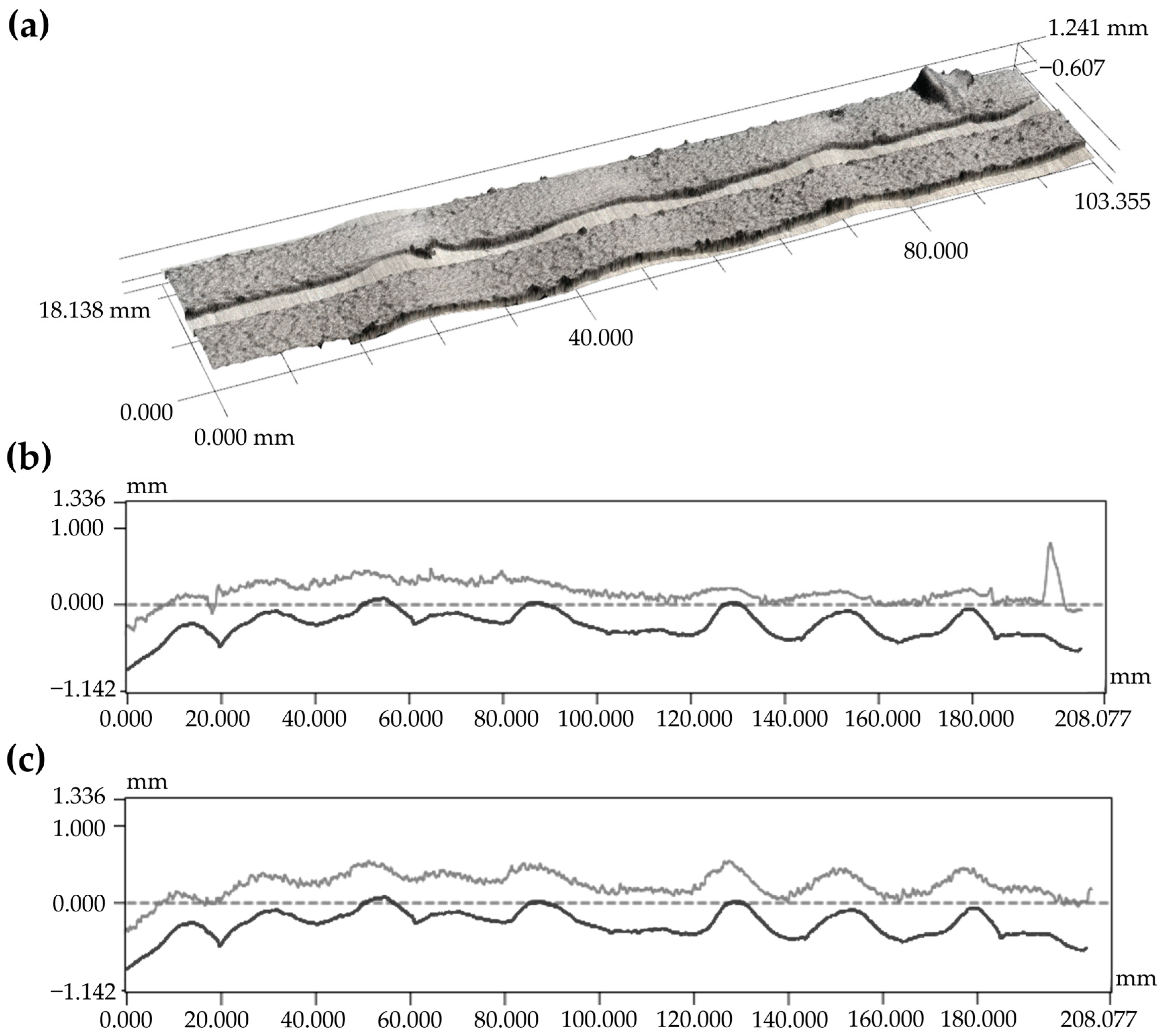
- Local defects such as gaps and overlaps have no significant influence on bonding;
- Recording the real geometry and taking it into account in the path planning is essential for a stable process.
Author Contributions
Funding
Data Availability Statement
Conflicts of Interest
References
- Shekar, R.I.; Kotresh, T.M.; Rao, P.M.D.; Kumar, K. Properties of high modulus PEEK yarns for aerospace applications. J. Appl. Polym. Sci. 2009, 112, 2497–2510. [Google Scholar] [CrossRef]
- Zalaznik, M.; Kalin, M.; Novak, S. Influence of the processing temperature on the tribological and mechanical properties of poly-ether-ether-ketone (PEEK) polymer. Tribol. Int. 2016, 94, 92–97. [Google Scholar] [CrossRef]
- Wang, H.Y.; Li, C.Y.; Ding, Y.M.; Li, J.; Chen, S.C. Experimental study on repairing of damaged cast iron cylinder heads by 3D printing arc welding system. In Proceedings of the 7th Global Conference on Materials Science and Engineering, Wuhan, China, 19–20 April 2019. [Google Scholar] [CrossRef]
- Hümbert, S.; Meth, J.; Echsel, M.; Lengowski, M.; Stäbler, T. Additve manufacturing of radiation shielding for small satellites. In Proceedings of the 72nd International Astronautical Congress (IAC), Dubai, United Arab Emirates, 25–29 October 2021. [Google Scholar]
- Matkovic, N.; Kupzik, D.; Steidle-Sailer, C.; Friedmann, M.; Fleischer, J. Novel Robot-Based Process Chain for Flexible Production of Thermoplastic Components with CFRP Tape Reinforced Structures. Proc. CIRP 2022, 106, 21–26. [Google Scholar] [CrossRef]
- Hümbert, S.; Schmidt, I.; Atzler, F.; Lengowski, M. Mechanical characterization of in-situ bonding between PEEK filaments and laminates in the FFF process. In Proceedings of the ECCM20, Lausanne, Switzerland, 26–30 June 2022. [Google Scholar]
- Caprais, I.; Joyot, P.; Duc, E.; Deseur, S. Bonding between high-performance polymer processed by Fused Filament Fabrication and PEEK/carbon fiber laminate. In Proceedings of the ESAFORM2021, Online, 14–16 April 2021. [Google Scholar] [CrossRef]
- Harik, R.; Saidy, C.; Wiliams, S.J.; Gurdal, Z.; Grimsley, B. Automated Fiber Placement Defect Identity Cards: Cause, Anticipation, Existence, Significance, and Progression; University of South Carolina: Columbia, SC, USA, 2018. [Google Scholar]
- Heinecke, F.; Willberg, C. Manufacturing-Induced Imperfecions in Composite parts Manufactures via Automated Fiber Placement. J. Compos. Sci. 2019, 3, 56. [Google Scholar] [CrossRef]
- Zenker, T.; Bruckner, F.; Drechsler, K. Effects of defects on laminate quality and mechanical performance in thermoplastic Automated Fiber Placement-based process chains. Advanced manufacturing: Polym. Compos. Sci. 2019, 5, 184–205. [Google Scholar] [CrossRef]
- Fereidouni, M.; Hoa, S.V. In-situ consolidation of thermoplastic composites by automated fiber placement: Characterization of defects. J. Thermoplast. Compos. Mater. 2024. [Google Scholar] [CrossRef]
- Sawicki, A.; Minguett, P. The effect of intraply overlaps and gaps upon the compression strength of composite laminates. In Proceedings of the 39th AIAA/ASME/ASCE/AHS/ASC Structures, Structural Dynamics, and Materials Conference and Exhibit, Long Beach, CA, USA, 20–23 April 1998. [Google Scholar]
- Falcó, O.; Lopes, C.S.; Mayugo, J.A.; Gascons, N.; Renart, J. Effect of tow-drop gaps on the damage resistance and tolerance of Variable-stiffness panels. Compos. Struct. 2014, 116, 94–103. [Google Scholar] [CrossRef]
- Raps., L.; Schiel, I.; Chadwick, A.R. Effect of gap defects on in-situ AFP-manufactured structures. In Proceedings of the 20th European Conference on Composite Materials, Lausanne, Switzerland, 26–30 June 2022. [Google Scholar]
- Lipskas, J.; Deep, K.; Yao, W. Robotic-Assisted 3D Bio-printing for Repairing Bone and Cartilage Defects through a Minimal Invasive Approach. Sci. Rep. 2019, 9, 3746. [Google Scholar] [CrossRef] [PubMed]
- Ma, K.; Zhao, T.; Yang, L.; Wang, P.; Jin, J.; Teng, H.; Xia, D.; Zhu, L.; Jiang, Q.; Wang, X. Application of robotuicassited in situ 3D printing in cartilage regeneration with HAMA hydrogel: An in vivo study. J. Adv. Res. 2020, 23, 123–132. [Google Scholar] [CrossRef] [PubMed]
- Li, L.; Shi, J.; Ma, K.; Jin, J.; Wang, P.; Liang, H.; Cao, Y.; Wang, X.; Jiang, Q. Robotic in situ 3D bio-printing technology for repairing large segmental bone defects. J. Adv. Res. 2021, 30, 75–84. [Google Scholar] [CrossRef] [PubMed]
- Li, L.; Yu, F.; Shi, J.; Shen, S.; Tang, H.; Yang, J.; Wang, X.; Jiang, Q. In situ repair of bone and cartilange defects using 3D scanning and 3D printing. Sci. Rep. 2017, 7, 9416. [Google Scholar] [CrossRef] [PubMed]
- Zhang, Y.; Qiao, J.; Thang, G.; Tian, H.; Li, L. Artifical Intelligence-Assited Repair System for structural and Electrical Restoration Using 3D Printing. Adv. Intell. Syst. 2022, 4, 2200162. [Google Scholar] [CrossRef]
- Raps, L.; Atzler, F.; Chadwick, A.R.; Voggenreiter, H. In-situ automated fiber placement gap defect filled by fused granular fabrication. Manuf. Lett. 2024, 40, 125–128. [Google Scholar] [CrossRef]
- Jin, L.; Zhai, X.; Wang, K.; Zhang, K.; Wu, D.; Nazir, A.; Jiang, J.; Liao, W.-H. Big data, machine learning, and digital twin assisted additive manufacturing: A review. Mater. Des. 2024, 244, 113086. [Google Scholar] [CrossRef]
- Ensinger GmbH. TECACOMP PEEK 150 CF30 Black 1015086—Compounds. Available online: https://www.ensingerplastics.com/en/compounds/cf-peek-compound-tecacomp-peek-150-cf30-black (accessed on 14 December 2022).
- Toray Advanced Composites Toray Cetex® TC1225—Product Data Sheet. Available online: https://www.toraytac.com/product-explorer/products/gXuK/Toray-Cetex-TC1225 (accessed on 10 March 2024).
- ASTM D3846-08(2015); Standard Test Method for In-Plane Shear Strength of Reinforced Plastics. ASTM International: West Conshohocken, PA, 2015.
- Ahlers, D.; Zhang, J.; Hendrich, N. 3D Printing of Nonplanar Layers for Smooth Surface Generation. Master’s Thesis, University of Hamburg, Hamburg, Germany, 2018. [Google Scholar]
- Wu, W.; Geng, P.; Li, G.; Zhao, D.; Zhang, H.; Zhang, J. Influence of layer thickness and raster angle on the mechanical properties of 3d-printed PEEK and a comparative study between PEEK and ABS. Materials 2015, 8, 5271. [Google Scholar] [CrossRef] [PubMed]
- Coogan, T.J.; Kazmer, D.O. Prediction of Interlayer Strength in Material Extrusion Additive Manufacturing. Addit. Manuf. 2020, 35, 101368. [Google Scholar] [CrossRef]
- Yi, N.; Chen, Y.; Shen, J.; Davies, R.; Ghita, O. Correlation between interfacial bond strength and degree of healing in overprinting PAEK on CF/PAEK composites. Compos. Part A 2024, 183, 108217. [Google Scholar] [CrossRef]


| Property | TECACOMP PEEK 150 CF30 |
|---|---|
| Density/g/cm3 | 1.38 |
| Young’s modulus/MPa | 17,500 |
| Ultimate strength/MPa | 190 |
| Nozzle temperature/°C | 400–440 |
| Bed temperature/°C | 130–160 |
| Parameter | Value |
|---|---|
| Nozzle temperature/°C | 420 |
| Temperature of heating zone1/°C | 420 |
| Temperature of heating zone2/°C | 420 |
| Temperature of print bed/°C | 280 |
| Ambient temperature/°C | 30 |
| Printing speed/mm/s | 20 |
| Layer height/mm | 0.6 |
| Nozzle diameter/mm | 3.0 |
| Laminate Defect | Effect on Overprinting | Tested Property |
|---|---|---|
| Gaps | Local underextrusion in the first layer | Bond strength parallel to the defect Bond strength perpendicular to the defect |
| Overlaps | Local overextrusion in the first layer | Bond strength parallel to the defect Bond strength perpendicular to the defect |
| Warpage/Waviness | Over-/underextruson in the first layer Over-/underextruson within 3D print | Bond strength at ±0.2 mm layer height error Inter-laminar strength of 3D print at ±0.2 mm layer height error |
Disclaimer/Publisher’s Note: The statements, opinions and data contained in all publications are solely those of the individual author(s) and contributor(s) and not of MDPI and/or the editor(s). MDPI and/or the editor(s) disclaim responsibility for any injury to people or property resulting from any ideas, methods, instructions or products referred to in the content. |
© 2024 by the authors. Licensee MDPI, Basel, Switzerland. This article is an open access article distributed under the terms and conditions of the Creative Commons Attribution (CC BY) license (https://creativecommons.org/licenses/by/4.0/).
Share and Cite
Atzler, F.; Hümbert, S.; Voggenreiter, H. A Workflow for the Compensation of Substrate Defects When Overprinting in Extrusion-Based Processes. J. Manuf. Mater. Process. 2024, 8, 147. https://doi.org/10.3390/jmmp8040147
Atzler F, Hümbert S, Voggenreiter H. A Workflow for the Compensation of Substrate Defects When Overprinting in Extrusion-Based Processes. Journal of Manufacturing and Materials Processing. 2024; 8(4):147. https://doi.org/10.3390/jmmp8040147
Chicago/Turabian StyleAtzler, Fynn, Simon Hümbert, and Heinz Voggenreiter. 2024. "A Workflow for the Compensation of Substrate Defects When Overprinting in Extrusion-Based Processes" Journal of Manufacturing and Materials Processing 8, no. 4: 147. https://doi.org/10.3390/jmmp8040147