Article

Effects of Layer Thickness and Compaction Thickness on Green Part Density in Binder Jetting Additive Manufacturing of Silicon Carbide: Designed Experiments

by
Mostafa Meraj Pasha
1,*,
Md Shakil Arman
1,
Fahim Khan
1,
Zhijian Pei
1 and
Stephen Kachur
2
1
Department of Industrial & Systems Engineering, Texas A&M University, College Station, TX 77843, USA
2
Product Development, CPS Technologies Corp., Norton, MA 02766, USA
*
Author to whom correspondence should be addressed.
J. Manuf. Mater. Process. 2024, 8(4), 148; https://doi.org/10.3390/jmmp8040148
Submission received: 10 June 2024 / Revised: 4 July 2024 / Accepted: 6 July 2024 / Published: 9 July 2024

Abstract

:
This paper reports on an experimental investigation that used a full factorial design to study the main effects and the interaction effect of layer thickness and compaction thickness on the green part density in the binder jetting additive manufacturing of silicon carbide. A two-variable, two-level full factorial design was employed. The results show that the green part density was higher at the low level of layer thickness and at the high level of compaction thickness. These results can be useful in selecting the values of printing variables, enabling the fabrication of green parts with a desirable density that is crucial for advanced ceramic applications.

1. Introduction

Additive manufacturing (AM), also known as 3D printing, refers to fabricating 3D objects by depositing material layer by layer according to a 3D model [1,2]. One of the seven main AM categories is binder jetting [3]. In binder jetting, a liquid binding agent is used to selectively create bonds between adjacent particles of the powder bed to print “green” parts. Afterward, post-printing processes (such as debinding, sintering, or infiltration) are usually required to turn the green parts into final products [4,5]. Figure 1 illustrates the basic steps of binder jetting with powder bed compaction. Note that compaction is not available on all binder jetting printers [6]. Also, in the illustration of binder jetting, powder is dispensed from a hopper onto the powder bed. There are other ways to dispense powder [3,7].
In step 1, the build platform is lowered by a distance equal to the sum of the layer thickness (LT) and compaction thickness (CT); to dry the powder, a heat lamp moves over the powder bed from left to right. In step 2, the hopper dispenses the powder while moving across the powder bed from right to left. Concurrently, a roller spreads the powder from right to left in a counter-rotating manner. In step 3, the build platform is raised by a distance equal to the compaction thickness. To compact the spread powder layer, the same roller then moves from left to right. In step 4, the print head deposits the liquid binder onto the selected powder bed regions according to a 3D model. These steps are repeated until the entire part is printed [4].
Binder jetting offers many advantages, including low operating expenses, the absence of thermal stresses, the elimination of support structures for parts with overhang structures, enhanced production rates, better powder recyclability, and the capability to print a wide array of materials [8,9,10,11]. Widely used in binder jetting are ceramic materials, including silicon carbide, due to their exceptional properties, such as high hardness, high temperature resistance, and excellent thermal properties [12,13]. Silicon carbide parts fabricated with binder jetting were proposed to be used in various applications, such as gas turbine engines [12], gear products [13], and heat exchangers [14]. For these applications, low density and strength remain an issue for silicon carbide parts prepared via binder jetting [15]. In the binder jetting process, the green part density has significant effects on the density and mechanical properties of the final parts. A high and uniform green part density minimizes the shrinkage, porosity, and defects during sintering, leading to stronger and more reliable final parts [4,8,11]. Various studies highlighted the significant impact of the printing variables on the green part density in binder jetting. For example, researchers investigated the green part density by changing the printing variables, such as the layer thickness [16,17,18,19,20], compaction thickness [4], roller traverse speed [16], binder saturation [21], and ultrasonic intensity [19].
In binder jetting, the layer thickness is usually selected based on a powder particle size [11] that is approximately two to three times the size of the largest powder particles [8,22,23,24,25,26,27,28,29]. There have been reported studies regarding the effects of layer thickness on the powder bed density [23,30] and green part density [16,17,18,20]. However, the results from these reported studies were inconsistent. For example, in one study, the powder bed density increased with increased layer thickness [23], whereas in another study, an increase in layer thickness led to a decrease in the powder bed density [30]. Table 1 summarizes the relevant reported studies on the green part density. In these studies, partial factorial designs or limited experimental runs were used. There have been no reported studies where a full factorial design was used.
In several reported studies on binder jetting, powder bed compaction was applied using a roller to increase the powder bed density [24,31,32,33]. Moghadasi et al. studied the effects of compaction thickness on the powder bed density and part density using nano-powders without replications of the experimental runs [4]. In addition, they studied the effects of compaction thickness by changing one variable at a time. No reported studies on the compaction thickness used a full factorial design. Therefore, interaction effects of compaction thickness with other variables are not known. Moreover, to date, no studies have explored the effects of compaction thickness on micro-powders.
The reported studies often relied on fractional factorial designs or limited experimental runs, which are unable to fully capture the interaction effects between variables. Moreover, no studies have specifically addressed the main effects and interaction effect of the layer thickness and compaction thickness on the green part density for binder jetting of silicon carbide powder using a full factorial design. This study aimed to address this gap by employing a full factorial design. Organized into four sections, this paper begins with an introduction. Section 2 details the experimental methods. Section 3 analyzes the main effects and interaction effect of the layer thickness and compaction thickness on the green part density. Lastly, Section 4 presents the conclusions drawn from this study.

2. Experimental Methods

2.1. Feedstock Powder

The silicon carbide powder used in this study was supplied by Electro Abrasives LLC, Buffalo, NY, USA. The average diameter of this powder was 7 µm, according to the particle size distribution (PSD), with a size range of 3 to 14 µm, which was obtained using a laser scattering particle size distribution analyzer (Horiba LA-960, Kyoto, Japan).

2.2. Binder Jetting of Green Parts

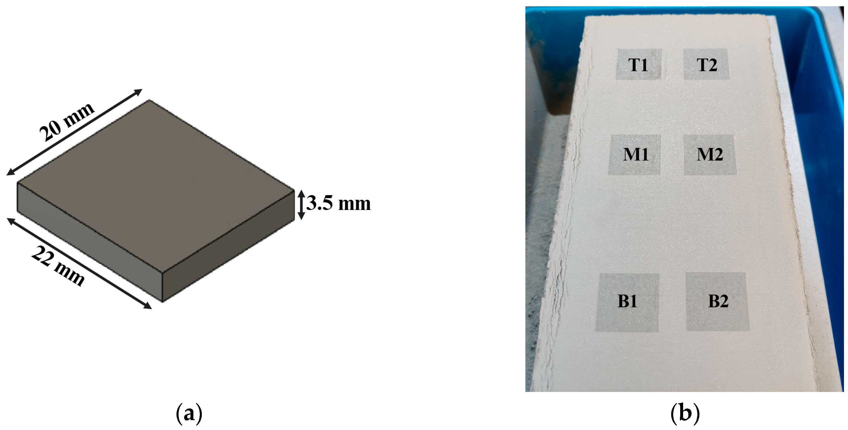
CAD (computer-aided design) software (Creo parametric v 9.0, Boston, MA, USA) was utilized to create the 3D model of the printed parts. The dimensions of the parts were 22 mm (length) × 20 mm (width) × 3.5 mm (thickness), as shown in Figure 2a. Then, the same CAD software was used to generate the STL file of the designed 3D model. Before printing, the STL file was converted into G-code, which included detailed instructions for the printer’s operation. Six green parts were printed in each experimental run. They were positioned on the XY plane with their thickness aligned with the build (Z) direction. These parts were identified using specific labels to indicate their locations on the build box: “T1” and “T2” for the top zone, “M1” and “M2” for the middle zone, and “B1” and “B2” for the bottom zone, as shown in Figure 2b.
An ExOne Innovent+ binder jetting printer (Innovent+, ExOne Company, North Huntington, PA, USA) and an aqueous binder (BA005, ExOne Company, North Huntington, PA, USA) were utilized. In this study, 1 kg of silicon carbide powder was placed into the mixing jar of a mixer (Mixomat mini, Fuchs Maschinen AG, Granges-Paccot, Switzerland). The powder was mixed for 5 min in the mixer jar with the mixer rotating at 55 rpm. After mixing, the mixed powder was kept in an oven (DX402C, Yamato Scientific, Tokyo, Japan) at 125 °C for 5 h to remove moisture from the powder. After cooling down the heated powder, a sieve was used to remove any agglomerates from the powder and the sieved powder was transferred into the hopper of the printer. Two heating pads (4 × 5 inch, ABN-4576, ABN, SD, USA) were attached to two of the hopper’s outer walls to keep the powder temperature constant.
Table 2 shows the values of the printing variables that were kept constant. The definitions of these variables can be found in the literature [4]. The value of each printing variable was determined by conducting preliminary trials that aimed to achieve a desirable powder bed quality (e.g., minimal surface defects) and green part quality (e.g., adequate strength).
After printing, the printed parts underwent curing in an oven (DX402C, Yamato Scientific, Japan) for 5 h at 125 °C. This curing aimed to enhance the mechanical strength of the green parts in preparation for the subsequent depowdering process [6].

2.3. Design of Experiments

In this study, a 22 (two variables, two levels, and four conditions) full factorial design was used. Unlike the Taguchi method, which focuses on orthogonal arrays and fractional designs to reduce the number of experiments [34], the full factorial design at two levels with replicas ensures testing all possible combinations of variable levels without requiring a large number of experimental runs [18,35]. The full factorial design has been used in many reported studies to assess the main and interaction effects of input variables on output variables [36,37,38]. Pei and Strasbaugh employed a three-variable, two-level full factorial design to investigate the main and interaction effects of three input variables in fine grinding of silicon wafers on five output variables. Rahman et al. utilized a three-variable, two-level full factorial design to evaluate the main and interaction effects of three input variables on four output variables in electrohydrodynamic printing. Yap et al. employed a three-variable, two-level full factorial design to investigate the main and interaction effects of three input variables on three output variables in material jetting additive manufacturing using a rigid opaque material. Many textbooks, including the one written by DeVor et al. [39], have comprehensive explanations of factorial design.
The two input variables in this study were layer thickness and compaction thickness. Table 3 displays the values of the variables at each level. The use of the two-level factorial design in this study was based on the assumption that the change in the green part density is approximately linear (or monotonic) when an input variable varies between the two levels. This assumption was reasonable in this study for the following reasons. In some of the authors’ previous binder jetting experiments, one input variable was changed at a time. As an input variable changed, the sintered part density changed approximately linearly. For example, Moghadasi et al. varied the compaction thickness across 6 levels (0, 5, 10, 15, 20, and 60 µm) while keeping the layer thickness fixed at 5 µm, and reported that the powder bed density and sintered density increased approximately linearly with the increasing level of the compaction thickness [4]. Furthermore, the two levels in this study were not too far apart, making non-monotonic changes between the two levels less likely.
Three replications were done for each experimental condition. Minitab statistical software (version 22.1.0) was used to generate a random experiment order. Table 4 displays the matrix of experiments.

2.4. Green Part Density Measurement

The green density ( ρ ) of the printed parts was calculated from geometrical and mass measurements. Using a slide caliper (500-196-30 digimatic 0–6″/150 MM stainless steel digital caliper, Mitutoyo, Japan), geometrical measurements (length, width, and thickness) of the parts were taken. A weight scale with a resolution of 0.001 g was used for the mass measurements. The green part density was then calculated using Equation (1), where m represents the mass of the part, and l, w, and t signify the length, width, and thickness of the part, respectively.
G r e e n   p a r t   d e n s i t y ,   ρ = m l w t

3. Results and Discussion

Because the location of the part in the print box also affects the green part density and the density variation of parts in the same experiment run was large [40], including more than one part in each experiment run could cause too large variations in the density data collected. To avoid introducing a confounding factor and ensure obtaining reliable ANOVA (analysis of variance), the data analysis included only one part at the same location in the print box (B2 as illustrated in Figure 2b) for each experiment run. Table 5 is the ANOVA table for the effects of the layer thickness and compaction thickness on the green part density. It was generated using the Minitab statistical software. The same software was used to generate both the main effect plots and the interaction effect plot.

3.1. Main Effect of Layer Thickness

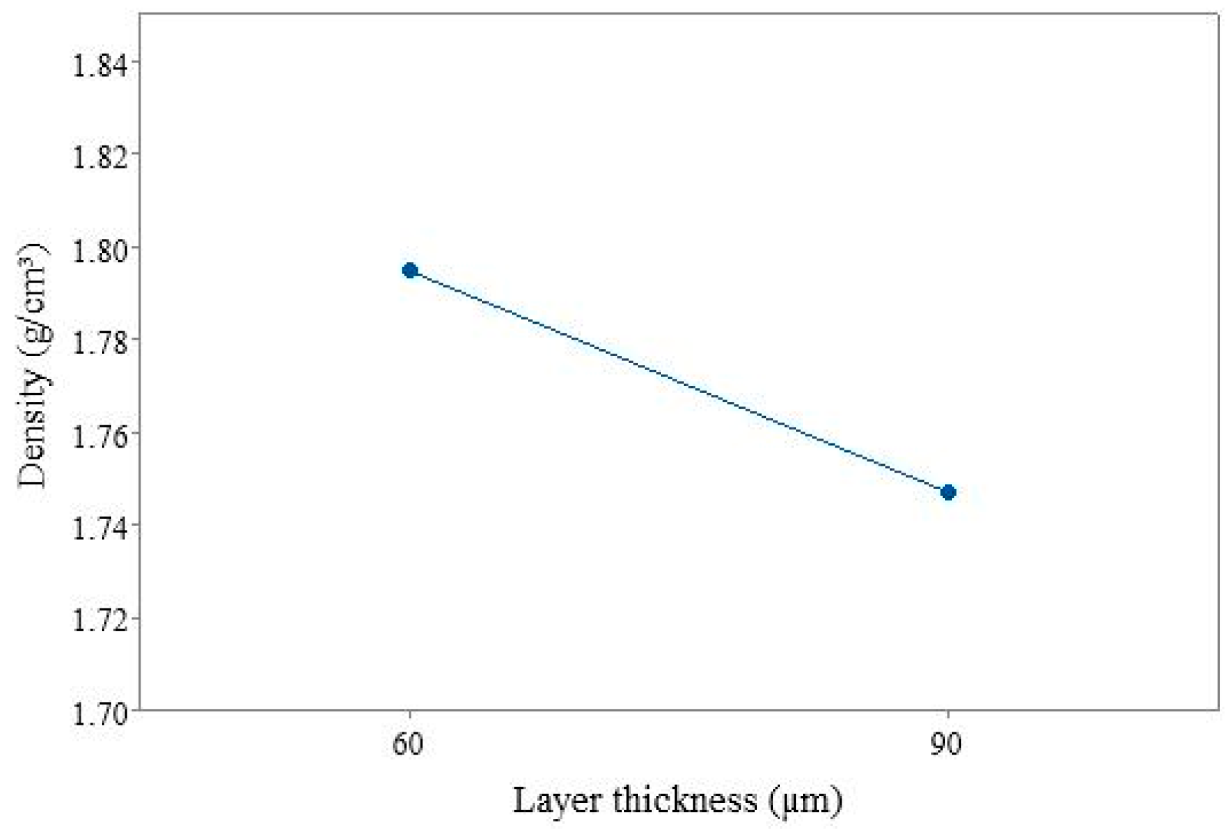
Figure 3 shows the main effect plot of the layer thickness on the green part density. It can be observed that the green part density fabricated with silicon carbide powder was higher at the low level of layer thickness. The green part density was improved by 4.8% when the layer thickness was reduced from 90 to 60 µm. This was likely due to the lower layer thickness facilitating a higher packing density in the powder bed [18,20]. Additionally, a lower layer thickness allowed for better binder penetration, which led to stronger inter-particle bonds and a higher green part density [8]. The trend observed from this study is consistent with the reported trend that a lower level of layer thickness results in a higher green part density [16,17,18,31]. Chen et al. used stainless steel 316L powder with particle sizes that ranged from 24 to 50 µm. They observed a 1% improvement in the green part density when the layer thickness was reduced from 150 to 125 µm [16]. Rishmawi et al. used iron powder with particle sizes of less than 45 µm and found a 5.5% green part density improvement when the layer thickness was reduced from 125 to 75 µm [31]. Barthel et al. used stainless steel 316L powder with particle sizes that ranged from 5.1 to 20.1 µm and a layer thickness that varied from 30 to 70 μm [18]. Lecis et al. used stainless steel 316L powder with particle sizes of 2.1 to 7.8 µm and a layer thickness that varied from 50 to 100 μm. Both Barthel et al. and Lecis et al. found that lower levels of layer thickness resulted in a higher green part density [17]. Shanjani and Ehsan developed an analytical model to predict the powder bed density at different levels of layer thickness. Their findings indicate that as the layer thickness increases, the powder bed density decreases [30].

3.2. Main Effect of Compaction Thickness

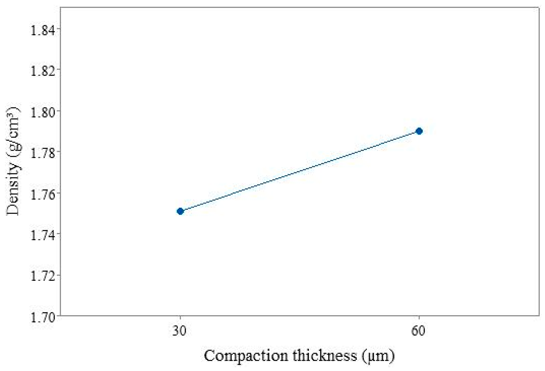
Figure 4 shows the main effect plot of the compaction thickness on the green part density. The green part density was higher at the high level of compaction thickness. A 4% improvement in the green part density was achieved when the compaction thickness was increased from 30 to 60 µm. This was likely because the higher compaction thickness ensured a uniform powder bed, which minimized the voids in the powder bed and facilitated particle rearrangement into a more closely packed structure, which hence resulted in a higher green part density [4]. The trend observed from this study is consistent with the reported trend that a higher level of compaction thickness results in a higher green part density [4]. Moghadasi et al. used alumina nano-powder with a particle size of around 100 nm. They observed a 2.5% improvement in the green part density when the compaction thickness was increased from 0 to 200 µm. Rishmawi et al. reported that applying roller compaction improved the green part density. However, they did not study the effects of the compaction thickness on the green part density [31].

3.3. Interaction Effect of Layer Thickness and Compaction Thickness

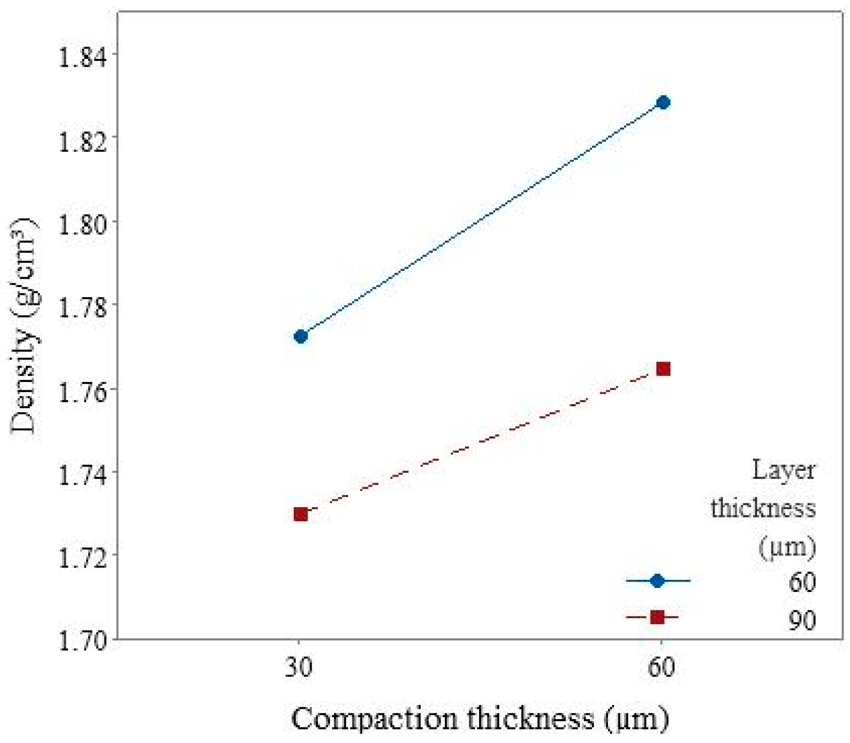
Figure 5 shows the interaction effect plot on the green part density between the layer thickness and compaction thickness. The x-axis represents the compaction thickness (µm), while the y-axis represents the green part density (g/cm3). The different levels of layer thickness (60 µm and 90 µm) are represented by two separate lines.
At both levels of layer thickness, there was a positive relationship between the compaction thickness and the green part density. However, the rate of increase in the density with increased compaction thickness was different at the two levels of layer thickness. At the low level of layer thickness (60 µm), the positive relationship between the compaction thickness and density was more pronounced, suggesting that a higher compaction thickness led to greater density gains. However, the rate of increase in density with the compaction thickness at the high level of layer thickness (90 µm) was slightly smaller than that at the low level of layer thickness (60 µm).

4. Conclusions

In this study, a full factorial design was used to investigate the main and interaction effects of layer thickness and compaction thickness on the green part density in the binder jetting of silicon carbide powder. The key findings of this study are given below:
  • Both the layer thickness and compaction thickness exhibited significant effects on the green part density.
  • The green part density was higher at the low level of layer thickness and at the high level of compaction thickness.
These results contribute to the fundamental understanding of the interaction between printing variables and density, providing a base to fabricate silicon carbide green parts with desirable density using binder jetting. Future research directions include analyzing the effects of the layer thickness and compaction thickness on the green part density and part quality using more levels of printing variables and using a more advanced experimental design (such as the response surface methodology).

Author Contributions

Conceptualization, M.M.P. and Z.P.; methodology, M.M.P.; software, M.M.P.; validation, M.M.P.; formal analysis, M.M.P.; investigation, M.M.P. and M.S.A.; resources, M.M.P., Z.P. and S.K.; data curation, M.M.P. and Z.P.; writing—original draft preparation, M.M.P.; writing—review and editing, M.M.P., M.S.A., F.K., Z.P. and S.K.; visualization, M.M.P. All authors have read and agreed to the published version of the manuscript.

Funding

This research received no external funding.

Data Availability Statement

Data are available upon reasonable request made to the authors.

Acknowledgments

The authors thank Taieba Tuba Rahman (Graduate student, Department of Industrial & Systems Engineering, Texas A&M University, College Station, TX 77843, USA) for her assistance in preparing the illustrations in this paper.

Conflicts of Interest

Authors Mostafa Meraj Pasha, Md Shakil Arman, Fahim Khan, and Zhijian Pei are employed by Texas A&M University, College Station, Stephen Kachur is employed by the company CPS Technologies Corp. The remaining authors declare that the research was conducted in the absence of any commercial or financial relationships that could be construed as a potential conflict of interest.

References

  1. Ngo, T.D.; Kashani, A.; Imbalzano, G.; Nguyen, K.T.; Hui, D. Additive manufacturing (3D printing): A review of materials, methods, applications and challenges. Compos. Part B Eng. 2018, 143, 172–196. [Google Scholar] [CrossRef]
  2. Sarila, V.; Koneru, H.P.; Pyatla, S.; Cheepu, M.; Kantumunchu, V.C.; Ramachandran, D. An Overview on 3D Printing of Ceramics Using Binder Jetting Process. Eng. Proc. 2024, 61, 44. [Google Scholar] [CrossRef]
  3. Chen, H.; Zhao, Y.F. Process parameters optimization for improving surface quality and manufacturing accuracy of binder jetting additive manufacturing process. Rapid Prototyp. J. 2016, 22, 527–538. [Google Scholar] [CrossRef]
  4. Moghadasi, M.; Miao, G.; Li, M.; Pei, Z.; Ma, C. Combining powder bed compaction and nanopowders to improve density in ceramic binder jetting additive manufacturing. Ceram. Int. 2021, 47, 35348–35355. [Google Scholar] [CrossRef]
  5. Doyle, M.; Agarwal, K.; Sealy, W.; Schull, K. Effect of layer thickness and orientation on mechanical behavior of binder jet stainless steel 420+ bronze parts. Procedia Manuf. 2015, 1, 251–262. [Google Scholar] [CrossRef]
  6. Moghadasi, M.; Du, W.; Li, M.; Pei, Z.; Ma, C. Ceramic binder jetting additive manufacturing: Effects of particle size on feedstock powder and final part properties. Ceram. Int. 2020, 46, 16966–16972. [Google Scholar] [CrossRef]
  7. Mao, Y.; Li, J.; Li, W.; Cai, D.; Wei, Q. Binder jetting additive manufacturing of 316L stainless-steel green parts with high strength and low binder content: Binder preparation and process optimization. J. Mater. Process. Technol. 2021, 291, 117020. [Google Scholar] [CrossRef]
  8. Mostafaei, A.; Elliott, A.M.; Barnes, J.E.; Li, F.; Tan, W.; Cramer, C.L.; Nandwana, P.; Chmielus, M. Binder jet 3D printing—Process parameters, materials, properties, modeling, and challenges. Prog. Mater. Sci. 2021, 119, 100707. [Google Scholar] [CrossRef]
  9. Ziaee, M.; Crane, N.B. Binder jetting: A review of process, materials, and methods. Addit. Manuf. 2019, 28, 781–801. [Google Scholar] [CrossRef]
  10. Li, M.; Du, W.; Elwany, A.; Pei, Z.; Ma, C. Metal binder jetting additive manufacturing: A literature review. J. Manuf. Sci. Eng. 2020, 142, 090801. [Google Scholar] [CrossRef]
  11. Du, W.; Ren, X.; Pei, Z.; Ma, C. Ceramic binder jetting additive manufacturing: A literature review on density. J. Manuf. Sci. Eng. 2020, 142, 040801. [Google Scholar] [CrossRef]
  12. Grady, J.E.; Halbig, M.C.; Singh, M. A fully non-metallic gas turbine engine enabled by additive manufacturing. In Proceedings of the International Symposium on Air Breathing Engines (ISABE 2015), Phoenix, AZ, USA, 25–30 October 2015. [Google Scholar]
  13. Lv, X.; Ye, F.; Cheng, L.; Fan, S.; Liu, Y. Fabrication of SiC whisker-reinforced SiC ceramic matrix composites based on 3D printing and chemical vapor infiltration technology. J. Eur. Ceram. Soc. 2019, 39, 3380–3386. [Google Scholar] [CrossRef]
  14. Thomas, J.; Banda, M.; Du, W.; Yu, W.; Chuang, A.; France, D.M.; Singh, D. Development of a silicon carbide ceramic based counter-flow heat exchanger by binder jetting and liquid silicon infiltration for concentrating solar power. Ceram. Int. 2022, 48, 22975–22984. [Google Scholar] [CrossRef]
  15. He, R.; Zhou, N.; Zhang, K.; Zhang, X.; Zhang, L.; Wang, W.; Fang, D. Progress and challenges towards additive manufacturing of SiC ceramic. J. Adv. Ceram. 2021, 10, 637–674. [Google Scholar] [CrossRef]
  16. Chen, W.; Chen, Z.; Chen, L.; Zhu, D.; Fu, Z. Optimization of printing parameters to achieve high-density 316L stainless steel manufactured by binder jet 3D printing. J. Mater. Eng. Perform. 2023, 32, 3602–3616. [Google Scholar] [CrossRef]
  17. Lecis, N.; Mariani, M.; Beltrami, R.; Emanuelli, L.; Casati, R.; Vedani, M.; Molinari, A. Effects of process parameters, debinding and sintering on the microstructure of 316L stainless steel produced by binder jetting. Mater. Sci. Eng. A 2021, 828, 142108. [Google Scholar] [CrossRef]
  18. Barthel, B.; Janas, F.; Wieland, S. Powder condition and spreading parameter impact on green and sintered density in metal binder jetting. Powder Metall. 2021, 64, 378–386. [Google Scholar] [CrossRef]
  19. Miyanaji, H.; Rahman, K.M.; Da, M.; Williams, C.B. Effect of fine powder particles on quality of binder jetting parts. Addit. Manuf. 2020, 36, 101587. [Google Scholar] [CrossRef]
  20. Jimenez, E.M.; Ding, D.; Su, L.; Joshi, A.R.; Singh, A.; Reeja-Jayan, B.; Beuth, J. Parametric analysis to quantify process input influence on the printed densities of binder jetted alumina ceramics. Addit. Manuf. 2019, 30, 100864. [Google Scholar] [CrossRef]
  21. Enneti, R.K.; Prough, K.C. Effect of binder saturation and powder layer thickness on the green strength of the binder jet 3D printing (BJ3DP) WC-12% Co powders. Int. J. Refract. Met. Hard Mater. 2019, 84, 104991. [Google Scholar] [CrossRef]
  22. Cheny, T.; Colin, C.; Verquin, B. Experimental evaluation of binder infiltration depth and axial overlap to control properties of green parts produced by Binder Jetting. Addit. Manuf. 2024, 87, 104231. [Google Scholar] [CrossRef]
  23. Meier, C.; Weissbach, R.; Weinberg, J.; Wall, W.A.; Hart, A.J. Critical influences of particle size and adhesion on the powder layer uniformity in metal additive manufacturing. J. Mater. Process. Technol. 2019, 266, 484–501. [Google Scholar] [CrossRef]
  24. Budding, A.; Vaneker, T.H. New strategies for powder compaction in powder-based rapid prototyping techniques. Procedia CIRP 2013, 6, 527–532. [Google Scholar] [CrossRef]
  25. Zhou, Z.; Mitchell, C.A.; Buchanan, F.J.; Dunne, N.J. Effects of Heat Treatment on the Mechanical and Degradation Properties of 3D-Printed Calcium-Sulphate-Based Scaffolds. Int. Sch. Res. Not. 2013, 2013, 750720. [Google Scholar] [CrossRef]
  26. Bredt, J.F.; Anderson, T.C.; Russell, D.B. Three Dimensional Printing Material System and Method. Google Patents US7087109B2, 8 August 2006. [Google Scholar]
  27. Vacanti, J.P.; Cima, L.G.; Cima, M.J. Vascularized Tissue Regeneration Matrices Formed by Solid Free Form Fabrication Techniques. Google Patents US6176874B1, 23 January 2001. [Google Scholar]
  28. Butscher, A.; Bohner, M.; Döbelin, N.; Galea, L.; Loeffel, O.; Müller, R. Moisture based three-dimensional printing of calcium phosphate structures for scaffold engineering. Acta Biomater. 2013, 9, 5369–5378. [Google Scholar] [CrossRef] [PubMed]
  29. Utela, B.; Storti, D.; Anderson, R.; Ganter, M. A review of process development steps for new material systems in three dimensional printing (3DP). J. Manuf. Process. 2008, 10, 96–104. [Google Scholar] [CrossRef]
  30. Shanjani, Y.; Toyserkani, E. Material Spreading and Compaction in Power-Based Solid Freeform Fabrication Methods: Mathematical Modeling; University of Texas Libraries: Austin, TX, USA, 2008. [Google Scholar] [CrossRef]
  31. Rishmawi, I.; Salarian, M.; Vlasea, M. Tailoring green and sintered density of pure iron parts using binder jetting additive manufacturing. Addit. Manuf. 2018, 24, 508–520. [Google Scholar] [CrossRef]
  32. Yoo, J. Fabrication and Microstructural Control of Advanced Ceramic Components by Three Dimensional Printing. Ph.D. Thesis, Massachusetts Institute of Technology, Cambridge, MA, USA, 1996. [Google Scholar]
  33. Yoo, J.; Cima, M.; Khanuja, S.; Sachs, E. Structural Ceramic Components by 3D Printing; University of Texas Libraries: Austin, TX, USA, 1993. [Google Scholar]
  34. Foteinopoulos, P.; Esnault, V.; Komineas, G.; Papacharalampopoulos, A.; Stavropoulos, P. Cement-based additive manufacturing: Experimental investigation of process quality. Int. J. Adv. Manuf. Technol. 2020, 106, 4815–4826. [Google Scholar] [CrossRef]
  35. Montgomery, D.C. Design and Analysis of Experiments; John Wiley & Sons: Hoboken, NJ, USA, 2017. [Google Scholar]
  36. Pei, Z.; Strasbaugh, A. Fine grinding of silicon wafers: Designed experiments. Int. J. Mach. Tools Manuf. 2002, 42, 395–404. [Google Scholar] [CrossRef]
  37. Rahman, T.T.; Arman, M.S.; Perez, V.; Xu, B.; Li, J. Analysis of the operating conditions of pulse electric field–assisted EHD for sodium alginate printing using design of experiment approach. Int. J. Adv. Manuf. Technol. 2021, 115, 2037–2047. [Google Scholar] [CrossRef]
  38. Yap, Y.L.; Wang, C.; Sing, S.L.; Dikshit, V.; Yeong, W.Y.; Wei, J. Material jetting additive manufacturing: An experimental study using designed metrological benchmarks. Precis. Eng. 2017, 50, 275–285. [Google Scholar] [CrossRef]
  39. DeVor, R.E. Statistical Quality Design and Control: Contemporary Concepts and Methods, 2nd ed.; Chang, T.-H., Sutherland, J.W., Eds.; Pearson/Prentice Hall: Upper Saddle River, NJ, USA, 2007. [Google Scholar]
  40. Dorula, M.; Khademitab, M.; Jamalkhani, M.; Mostafaei, A. Location dependency of green density and dimension variation in binder jetted parts. Int. J. Adv. Manuf. Technol. 2024, 132, 2853–2861. [Google Scholar] [CrossRef]
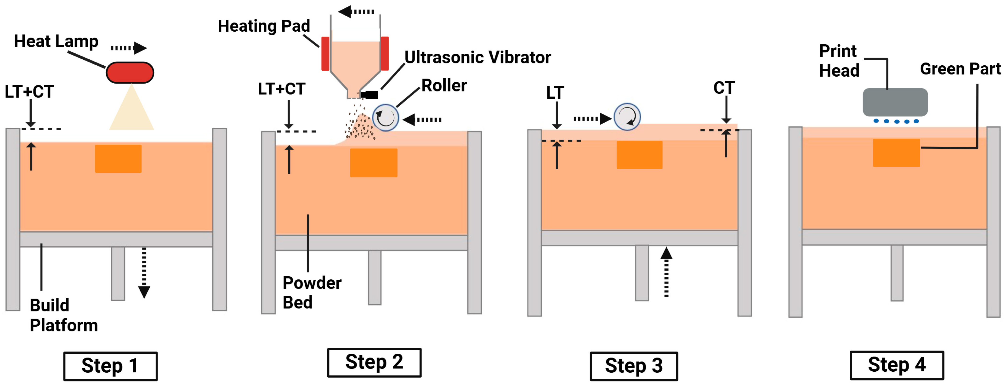
Figure 1. Illustration of four steps in binder jetting using powder bed compaction (layer thickness is represented by LT, and compaction thickness is represented by CT).
Jmmp 08 00148 g001
Figure 2. Design and labels of printed parts: (a) CAD model; (b) labels and locations on the build box.
Jmmp 08 00148 g002
Figure 3. Main effect of layer thickness on green part density.
Jmmp 08 00148 g003
Figure 4. Main effect of compaction thickness on green part density.
Jmmp 08 00148 g004
Figure 5. Interaction effect of layer thickness and compaction thickness on green part density.
Jmmp 08 00148 g005
Table 1. Relevant reported studies on effects of layer thickness on green part density in binder jetting.
VariablesExperimental DesignMaterialParticle Size (μm)Reference
Layer thickness and binder saturation4 experimental runsStainless steel 316L2.1–7.8[17]
Layer thickness, roller diameter, supply-to-spread ratio, and translational and rotational roller speedsFractional factorial design, 12 experimental runsStainless steel 316L5.1–20.1[18]
Layer thickness, binder saturation, and roller traverse speed14 experimental runsStainless steel 316L24–50[16]
Layer thickness, recoat speed, oscillator speed, roller speed, drying time, and saturation levelFractional factorial design, 18 experimental runsAluminum oxide20–40[20]
Roller actuation, layer thickness, and binder saturation12 experimental runsIron powder<45[31]
Table 2. Values of printing variables that were kept constant.
Printing VariableValue
Ultrasonic intensity (%)100
Roller traverse speed during spreading (mm/s)15
Roller traverse speed during compaction (mm/s)5
Roller rotation speed during spreading (rpm)300
Binder saturation (%)36.6
Binder set time (s)30
Bed temperature (°C)50
Drying time (s)15
Packing rate (%)48
Table 3. Values of variables at each level.
VariableLow Level (−)High Level (+)
Layer thickness (µm)6090
Compaction thickness (µm)3060
Table 4. Matrix of experiments.
Experimental OrderLayer ThicknessCompaction Thickness
3+
2+
1
4++
5
7+
9-
11+
6+
8++
10+
12++
Table 5. ANOVA table for effects of layer thickness and compaction thickness on green part density.
Source of VarianceDegree of FreedomSum of SquaresF-Valuep-Value
Model30.0117564.290.051
Linear20.0117556.430.026
Layer thickness (LT)10.0075648.280.024
Compaction thickness (CT)10.0054755.990.044
LT × CT10.0003030.330.583
Residuals70.006395
Disclaimer/Publisher’s Note: The statements, opinions and data contained in all publications are solely those of the individual author(s) and contributor(s) and not of MDPI and/or the editor(s). MDPI and/or the editor(s) disclaim responsibility for any injury to people or property resulting from any ideas, methods, instructions or products referred to in the content.