Article

Investigation of Metal Powder Blending for PBF-LB/M Using Particle Tracing with Ti-6Al-4V

Fraunhofer Research Institution for Additive Manufacturing Technologies IAPT, 21029 Hamburg, Germany
*
Author to whom correspondence should be addressed.
J. Manuf. Mater. Process. 2024, 8(4), 151; https://doi.org/10.3390/jmmp8040151
Submission received: 23 May 2024 / Revised: 2 July 2024 / Accepted: 13 July 2024 / Published: 16 July 2024
(This article belongs to the Special Issue Industry 4.0: Manufacturing and Materials Processing)

Abstract

:
Laser-based powder bed fusion of metals (PBF-LB/M) is the most used additive manufacturing (AM) technology for metal parts. Nevertheless, challenges persist in effectively managing metal powder, particularly in blending methodologies in the choice of blenders as well as in the verification of blend results. In this study, a bespoke laboratory-scale AM blender is developed, tailored to address these challenges, prioritizing low-impact blending to mitigate powder degradation. As a blending type, a V-shape tumbling geometry meeting the requirements for laboratory AM usage is chosen based on a literature assessment. The implementation of thermal oxidation as a powder marking technique enables particle tracing. Blending validation is achieved using light microscopy for area measurement based on binary image processing. The powder size and shape remain unaffected after marking and blending. Only a small narrowing of the particle size distribution is detected after 180 min of blending. The V-shape tumbling blender efficiently yields a completely random state in under 10 min for rotational speeds of 20, 40, and 60 rounds per minute. In conclusion, this research underscores the critical role of blender selection in AM and advocates for continued exploration to refine powder blending practices, with the aim of advancing the capabilities and competitiveness of AM technologies.

1. Introduction

Additive manufacturing (AM) has emerged as a promising technology for industrialization, with laser-based powder bed fusion of metals (PBF-LB/M) representing one of its most advanced methodologies [1]. In the PBF-LB/M process, metal powder is incrementally melted layer by layer, conforming to the part geometry to solidify into functional metal components [2]. While the PBF-LB/M process is gaining traction, the handling of metal powder, a pivotal element influencing part quality and costs, remains mainly unstandardized. According to VDI 3405 part 2.7, powder handling typically encompasses sieving, machine filling and emptying, and storage, with occasional additional steps such as drying or blending [3].
The blend of two or more powder types is classified as solid–solid blending, aiming for a homogeneous, completely random state [4,5,6]. Powders are blended through particle movement. Neighboring particles may exchange their positions, blending the powder boundaries through a mechanism known as dispersion. Alternatively, groups of particles may exchange positions in a mechanism known as convection. Both blending mechanisms occur simultaneously and overlap [7]. Segregation is a potential opposing movement of the particles, influenced by particle characteristics such as size, shape, and density [6,7,8]. Two common segregation mechanisms are slip-of-slope and percolation. Slip-of-slope refers to the separation of particles when they hit a heap, causing small particles to remain in the center, while large particles accumulate at the edges due to higher impact forces [6]. Percolation, also known as the Brazil nut effect, describes segregation due to vibrations, which create voids that small particles fill, while large particles move to the top [9].
Though principal blending mechanisms are well understood, the blending step in powder handling for PBF-LB/M remains underexplored. This presents opportunities for various applications, including powder refreshing, achieving desired particle size distributions (PSD), or alloy fabrication [10,11].
Investigations into the reuse of metal powder revealed effects such as oxygen uptake and coarsening of the particle size [12,13,14]. The high reactivity of aluminum and titanium with oxygen increases the oxygen pickup during multiple reuses [15]. Raza et al. measured an increase in the oxide layer thickness on the AlSi10Mg particle surface from 5 to 35 nm over 30 months using a closed-loop XLINE 200R machine from Concept Laser GmbH, GE [16]. Quintana et al. reused Ti-6Al-4V ELI powder for 31 cycles, observing an oxygen content increase from 0.09 wt.% to 0.13 wt.% inside a powder capsule and to 0.11 wt.% in the powder sample [14]. Soltani-Tehrani et al. investigated Ti-6Al-4V grade 5 powder with a PSD of 20–53 µm. After eight reuse cycles (eight build jobs), they detected an increase of 1–2 µm in particle size and oxygen pick-up from 0.13 to 0.14 wt.% [17]. Delacroix et al. identified an increase of 2–3 µm over 15 build jobs for 316 L powder with a PSD of 20–45 µm [18]. Investigations into powder refreshing remain relatively scarce. Lutter-Günther et al. described two recycling strategies: refreshing with virgin powder or mixing with powder of the same reuse stage [19]. Refreshing can lead to reducing the overall oxygen content and preserving smaller particle size fractions (≤25 µm), thereby facilitating prolonged reuse and minimizing powder waste [12]. The mixing of powders with the same reuse stage allows for equal degradation [19].
Typical PSDs for PBF-LB/M range from 10–44 µm to 20–63 µm, with potential for cost and resource reduction through the utilization of increased atomization yields [11,20,21,22]. To create further PSDs, Young et al. mixed a 15–25 and a 35–48 µm powder with a Turbula mixer. Details on the blending parameters are not presented [11]. Haferkamp et al. blended 14–27 µm and 50–75 µm powders to investigate the influence of bimodal PSDs on the part density. The blending was performed with a rotating cylindrical drum for 2 h. Neither the choice of blender nor the selection of the blending parameters were further described [23].
The development of new alloys for PBF-LB/M runs through the entire production chain and is therefore elaborate and time-consuming, particularly when pre-alloyed and atomized powders are required for each alloy iteration. Consequently, preliminary tests are frequently conducted using blended alloy compositions, with the final alloy composition refined through melting and solidification during PBF-LB/M. Ensuring homogeneous blends is imperative for reliable alloy testing [24,25,26]. The following studies present insights about the usage of powder blending, particularly for alloy fabrication: Ekaputra et al. used ball milling to blend irregularly shaped pre-alloyed Al-7Ce-10Mg powder with Zr and Sc powders as well as pre-alloyed Al-10Zr and Al-10Sc powders. Neither the choice of blender nor the determination of blending parameters were described [27]. Huang focused on the corrosion behavior of pre-alloyed and mixed powders. Pre-alloyed Ti6Al4V3Cu was compared to a Ti6Al4V (97 wt.%) mixed with Cu (3 wt.%) in a Turbula blender. Blending parameters or choice of blending parameters are not declared [25]. Thamae et al. investigated the blending of irregularly shaped SiC and spherical Ti6Al4V powders with a rotary batch mixer. After blending for 30 min, agglomerates occurred. No further information on rotational speed or the choice of blender was provided [10]. Li et al. blended duplex stainless steel and pure Ni powders in PE bottles for 48 h to analyze remelting effects on the homogeneity of the chemical elements [28]. Handtke et al. used a Turbula mixer for 2 h to blend iron powder with broken ferroalloy particles and elemental particles for alloy fabrication [29]. Parker blended individual elemental powders for 15 min at 250 rpm using a 3D-Turbula-like mixer in a plastic container to fabricate a Ti-6Al-4V alloy [30].
From the investigated studies, it became clear that a tumbling blender is the preferred blending methodology. In the literature considered, blending times ranged from 15 min to 48 h. Meanwhile, despite the significance of powder blending, detailed information on blending methodologies and parameters remains scarce in the existing literature for PBF-LB/M, particularly concerning reuse purposes.
Priyadarshi et al. investigated particle tracking using a high-speed camera and ultrafast synchrotron X-ray imaging to observe ultrasonic atomization. This setup allowed for a detailed in situ observation of individual drops and their evolution into particles [31]. Kohlwes et al. used a high-speed camera for in situ spatter tracking, developing analysis software to count and trace spatter movement [21]. However, setting up a high-speed camera for particle tracing in a rotating blending container is challenging, as particles cannot be traced consistently throughout the rotation. While both methods show promise for in situ particle tracing in atomization and the LPBF process, these advanced methodologies are beyond the scope of this study. Instead, a particle tracing method is employed based on measuring samples taken before and after blending to trace particles and validate the blending results.
The novelty of this work lies in its comprehensive approach to addressing the deficiencies in current powder blending practices for LPBF. This study provides a decision path for blender selection based on specific requirements, demonstrates a statistically based choice of blending parameters, and presents a method to validate the blending results. By developing a specialized laboratory-scale blender and a unique particle tracing method, this study enhances the understanding of effective blending techniques while pioneering solutions for user safety, powder degradation, and segregation challenges. Given the limited availability of powder blenders tailored for laboratory AM use, this research aims to establish requisite blending requirements and assess their fulfilment through the development and implementation of a bespoke powder blending methodology. The novel particle tracing method developed to validate blending efficacy further advances the state of the art in AM powder handling and blending technologies.

2. Materials and Methods

2.1. Blender Development
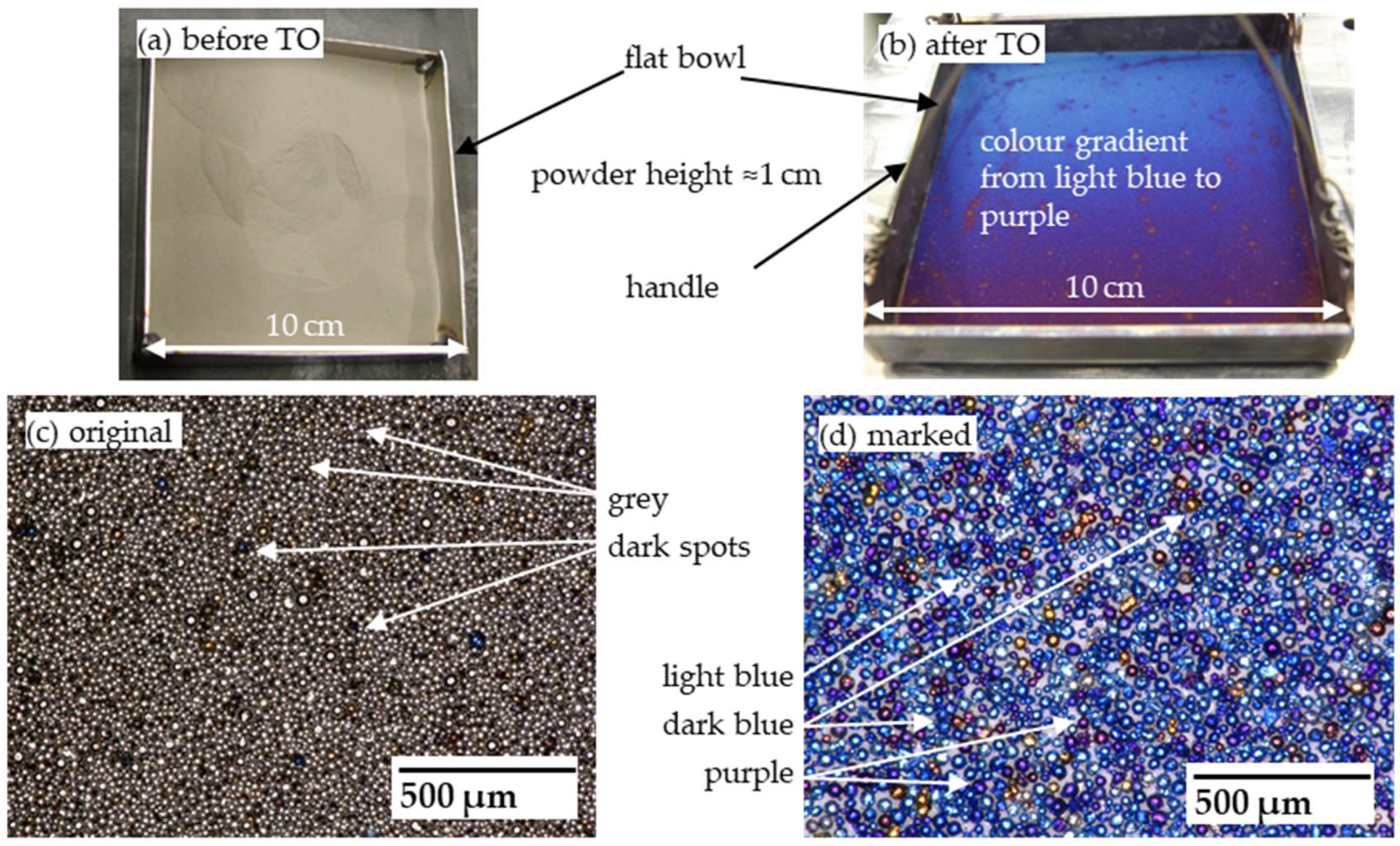
The blending of two powders was classified as solid–solid blending. Blending aims to uniformize the powders in a completely random state [4,6,32]. The requirements for powder blending in AM were selected across various categories, which are listed in Table 1. All requirements represent essential demands for the blender development. Primarily intended for laboratory experimentation, the blender should feature a volume of 3 L for discontinuous blending. The frame should be designed to fit larger blending containers (up to l0 L). A flexible suspension system should allow revisions in container sizing and container geometry.
Notably, a low-impact blending process was prioritized to prevent powder degradation in terms of size and shape. The impact of a blending process is defined with the Froude number Fr in Equation (1) [5,33].
F r = r ω 2 g
The equation is composed of the blending or blending tool radius r, the acceleration due to gravity g, and the angular velocity ω. The Froude number is the dimensionless ratio of centrifugal to gravitational acceleration. The lower the Froude number, the lower the impact and shear stresses on the powder. Different blending types were categorized by Müller according to their Froude number [7].
Subsequently, a suitable blender type was chosen through a structured evaluation process. Principles were defined as suitability, homogenization, lab scale, low-impact blending, complexity, blending time, and cleanability.
The pre-selected blending types—tumbling, convective, and pneumatic—met the requirements of low-impact (Fr < 1) and discontinuous blending. A tumbling blender is characterized by a rotating container to create a powder movement. Convective blenders move powder through blades or paddles, while the container itself is fixed. For pneumatic blending, a gas such as air or Ar is inserted through multiple inlets, which creates powder movement [6,9,34]. The blender types were assessed per each selected principle on a 5-level scale oriented on VDI-2225 part 3 [35]. The assessment was based on literature and qualitative evaluation.
Market research revealed a lack of suitable blenders that meet all demanded requirements. There are some blenders available in sizes such as 3 L that fulfil the safety requirements of earthing and inert gas atmosphere in the container. The flexibility to change the tumbling geometry with a possibility of upscaling for containers up to 10 L is the biggest hurdle.
Given the unavailability of AM laboratory-scale blenders, a bespoke powder blender was developed. Following the guidelines of VDI 2221 “Systematic approach to the development and design of technical systems and products”, the development process adhered to a systematic approach, ensuring consideration of the requirements listed in Table 1 [36].
The requirements for safety were geared to VDI 3405 part 6.1 [37]. The developed blending container was subjected to safety testing, comprising gas-tightness assessments and frame stability. Therefore, the blending container was filled with 2 bar Ar and submerged in a water bath to detect escaping gas. The pressure was tested after 24 h to check for gas tightness. The frame’s stability was tested with 60 min rotation trials with two chamber-filling levels empty and filled with water at increasing rotational speeds of 20, 40, 60, and 80 rounds per minute (rpm). The stability and the vibrations were monitored during the tests by the operator.

2.2. Powder Marking

To assess the blending efficiency, differentiation of the powders based on a specific criterion was imperative. Particle differentiation can be achieved through various characteristics such as size, density, or color. Color was chosen as the distinguishing criterion due to its high discernibility and negligible influence on powder properties and flow characteristics. Thermal oxidation (TO) was employed to impart a distinct color appearance to the metal particles. With this method, the Ti-6Al-4V reacts with the atmosphere to form a TiO2 layer on the particle surface. The exposure time and temperature determine the thickness of the oxide layer [38]. In this study, a Ti-6Al-4V powder was subjected to a furnace at 550 °C for 2 h in the atmosphere.
The generated nanometer-thin layer of oxygen is characterized by unique light refraction properties, resulting in a colorful appearance: 25–40 nm purple, 40–50 nm dark blue, 60 nm light blue. Therefore particles are differentiable by color [39,40,41].
To assess any potential effects of the marking process on blending behavior, powder characterization and comparison were conducted between the original and marked powders. The characteristics were assessed using dynamic image analysis according to ISO 13322-2, comparing the size and shape of the marked versus original particles [42]. The Camsizer X2 from Microtrac Retsch was used for this analysis as shown in Figure 1. Grayscale images of the particles were transformed into binary images, and algorithms were employed to identify and measure the particle outlines, determining their size and shape [43].
Flowability assessments were conducted to ascertain the absence of any marking-induced alterations in flow characteristics using standardized methods. Apparent and tapped density measurements were conducted with a Hall funnel, following protocols outlined in DIN EN ISO 3923-1 and DIN EN ISO 3953 [44,45]. The Hausner ratio was determined as part of this assessment [46]. Additionally, the Hall flowability was measured according to DIN EN ISO 4490 [47].

2.3. Verification of Blending Grade

The Ti-6Al-4V powder was divided into three batches, each blended with 10% marked powder at varying rotational speeds of 20, 40, and 60 rpm. Samples were systematically collected from the top and the bottom of the blending container at predefined intervals ranging from 1 to 10 min to quantify the evolution of the blending grade over time.
The samples were placed on a double metal plate with eight flat holes (0.5 mm depth) on the top layer. With this thin powder layer, the samples were measured in an optical light microscope VHX5000 from Keyence without a third medium in the background. With image analysis software, the images were binarized to cluster-marked and original particles. The percentage of the area of the marked particles was measured per each image and the mean value was compared to the 10% marked particle content. The results were represented in a box plot diagram to present the mean values as well as the distribution of the eight single results.
Additionally, to ensure the prevention of particle degradation, the powders were characterized before and after a prolonged blending duration of 180 min. For comparative analysis, the individual particle shape and size of both the original and marked powders were measured. Subsequently, reference values were computed based on a 90:10 ratio derived from the measured data. These reference values served as benchmarks for evaluating the blending process. The results obtained from blending for 180 min at rotational speeds of 20, 40, and 60 rpm were then juxtaposed with the calculated 90:10 reference particle shape and size, enabling an assessment of blending efficacy [42].
The comparison between the calculated 90:10 values and the actual powder sizes achieved after blending served as a second validation method for assessing the blending result of the powder intended for further processing in the PBF-LB/M.

3. Results

3.1. Development of Powder Blender

3.1.1. Blender Type Assessment

To select a discontinuous, laboratory scale blending type, a pre-selection was made for the three blending types: tumbling, convective, and pneumatic. The advantages of a tumbling system are particularly the low complexity, which reduces the costs and enables thorough cleaning. In addition, tumbling blenders are completely dischargeable [34]. Tumbling blenders with a rotating housing have a higher risk of overall segregation than convective blenders due to the large amount of powder that is moved in one rotation [6,9]. The convective blender features a higher complexity with multiple rotating tools inside the container. The cleanability is more complex and time-consuming. However, the degree of blending is of high homogeneity due to higher shear stresses compared to a tumbling blender. The movement of the blending tools prevents segregation [6]. Convective blenders are more common for continuous usage [6]. The pneumatic system is limited in usability. To reduce explosion and combustion risks, as well as to prevent further oxidation of the particles, an inert gas like argon or nitrogen is recommended. This is a cost lever compared to the other systems, which can be flooded with an inert gas without refilling during operation. Care must be taken to ensure that the sinking speeds of the particles are as similar as possible so that segregation does not occur [6]. Pneumatic blending has a comparatively high energy input [8]. The assessment of the tumbling, convective, and pneumatic blenders is summarized in Table 2.
The highest rating for the set requirements was obtained for the tumbling blender geometry. The tumbling blenders were classified with Fr < 1 by Rumpf. They are characterized by a low centrifugal force to gravity ratio and, therefore, have a low impact on the blend material [7]. Tumbling blenders feature low complexity, easy cleaning, and comparatively low costs. From the two most common tumbling geometries, the double-cone-shape and the V-shape, the V-shape was more promising for higher blending efficiency and simple cleaning [6,48]. This led to a decision for a V-shaped blender.

3.1.2. Development

First, the concept of a V-shaped blending container was developed, as shown in Figure 2a. Second, the V-shaped container was designed in CAD software (Inventor 2021) with all features integrated (Figure 2b). In the third step, the V-shaped container and the test rig were built (Figure 2c). Within the frame built of profiles, a rotation axis was constructed, driven by a brushless DC motor via a coupling mechanism and a planetary gearing system supported by spherical roller bearings. This setup accommodated the attachment of containers with a high degree of flexibility, allowing for variations in size and geometry. The electronic infrastructure, including a power supply unit, was centralized within a control cabinet, which also featured an integrated emergency stop switch for safety. Operational control of the motor was facilitated through a control unit interfaced with the manufacturing software, enabling the precise adjustment of rotational speed.
The sensors for monitoring the oxygen content and the overpressure were installed in the T-connection shown in Figure 2b. The oxygen content was measured when flooding with the inert gas, Ar. During blending, the overpressure was monitored to avoid gas leakage. The container was mounted using two attached wings, which were fixed to the test stand with two screws on each side. Figure 2c provides a visual representation of the blender test rig.
To assess the gas tightness of the container, a water bath test was performed. Minor adjustments to the wing nuts at the flanges on both legs allowed the gas to be trapped inside the container without any visible leakage. The container was kept at a pressure of 2 bar for 24 h. The test rig showed no vibrations or movement with an empty container at the three rotational speeds. When filled with water, slight vibrations were noticed without further movement at 60 rpm. The results met the requirements, which allowed for the blending of metal powders.

3.2. Verification of Blending Grade

3.2.1. Particle Marking

To mark the original powder as shown in Figure 3a,c, the furnace settings of 550 °C for a duration of 2 h led to the formation of an oxide layer approximately 40–50 nm thick, which manifested as a blue hue, as presented in Figure 3b,d. This enabled differentiation from the original gray particles.
To ensure comparability between the marked and original particles, the powder characteristics’ size, shape, and flowability were measured. Figure 4 depicts the frequency distribution of the particle sizes, revealing that the presence of the additional oxide layer did not induce significant coarsening.
The particle shape and the 10, 50, and 90% deciles are presented in Table 3. Notably, the morphology remained largely unaffected by the marking process, with a slight inclination towards increased regularity observed. Regarding the PSD, a minor reduction in fine particles was evident, accompanied by a slight rise in the D90 value.
The influence of the marked particles on the flowability was tested with a Hall funnel. The results for the apparent and tapped density, Hausner ratio, and Hall flowability are presented in Table 4.

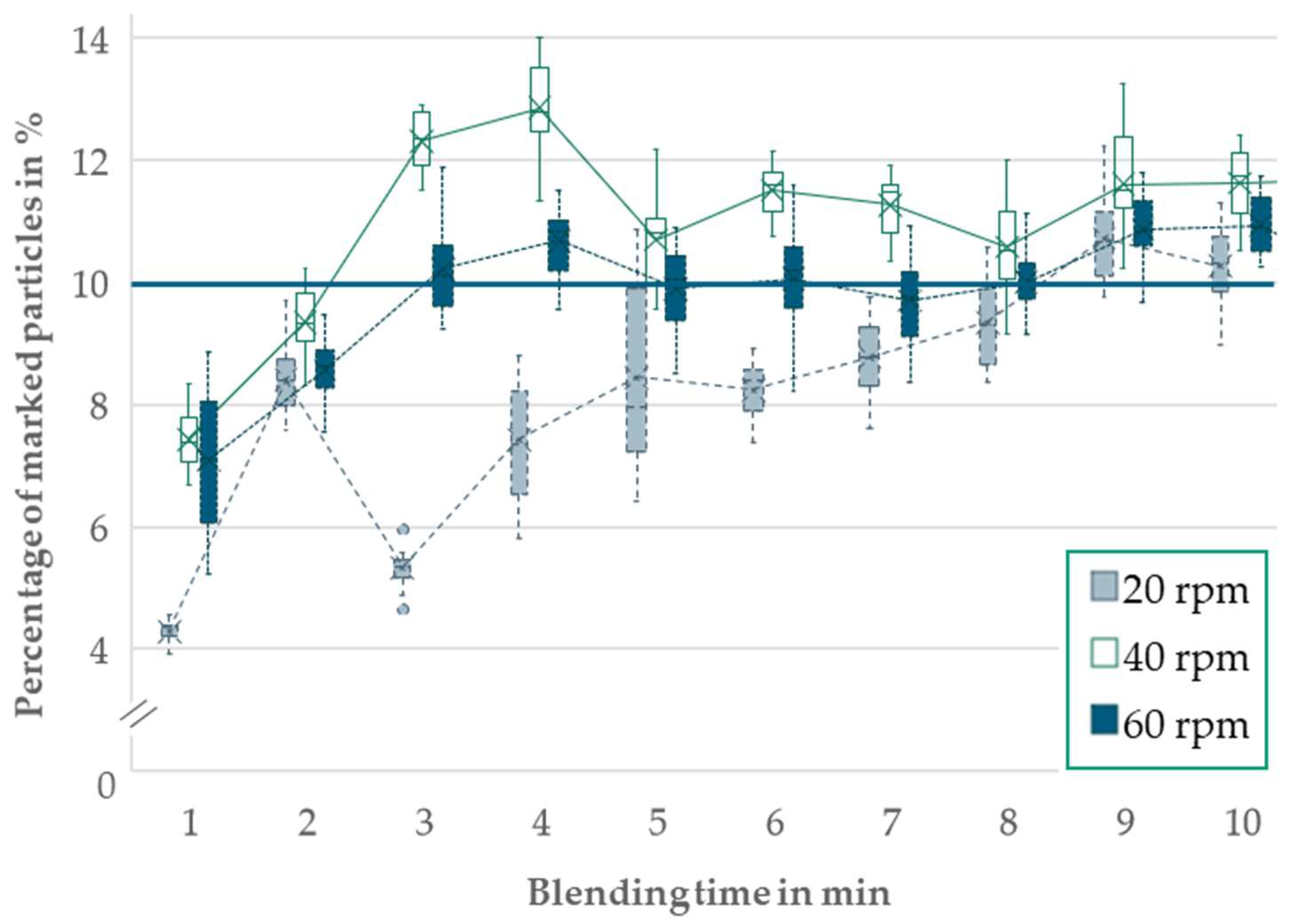
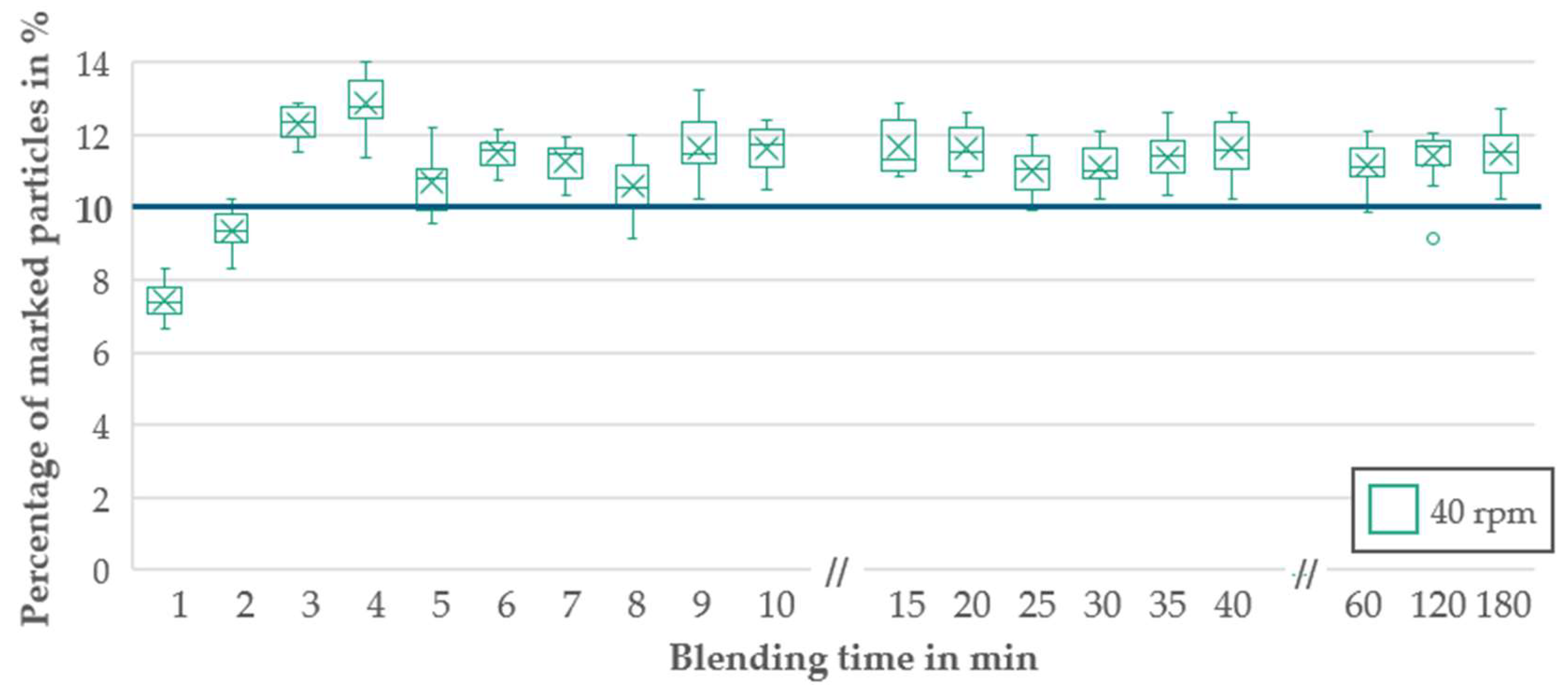
3.2.2. Blending Result

To determine the required blending duration at different rotational speeds, samples were collected every minute until reaching a 10 min interval for 20, 40, and 60 rpm rotational speed. The images taken with the light microscope are shown in Figure 5 for samples taken at the blending times of 1, 5, and 10 min at 20 rpm. The increase in marked particles was visible with increasing time. After 1 min, only a few single marked particles were detected. After 5 min, predominant clusters of the marked particles were detected. After 10 min, the marked particles were evenly distributed in the samples investigated.
In Figure 6, the percentage of marked particles detected in each sample over the blending time is shown. The desired blending result for 10% marked particles is highlighted by a blue bar. Notably, the slowest rotational speed of 20 rpm necessitated the longest duration, taking 9 min to achieve the 10% target. Conversely, at 60 rpm, 10% of marked particles were reached within 3 min. For the rotational speed of 40 rpm, 10% of marked particles consistently appeared after 5 min of blending.
During a prolonged test comprising 90% original and 10% marked particles, the blend was rotated within the blender for 180 min. Any occurrences of abrasion or deformation among the particles were assessed using dynamic image analysis; the results are presented in Table 5.
Following the 180 min blending period, no evidence of degradation or abrasion could be detected. The standard deviation of particle shapes remained below 0.01, indicating no significant change. However, a slight increase in particle size was observed for D10 and D50, while a marginal decrease was noted for D90. The blending results were measured at 1 min intervals for 10 min, and then at 5 min intervals for another 30 min (total blending time 40 min), and subsequently in 1 h intervals. The results for a rotational speed of 40 rpm are presented in Figure 7.

4. Discussion

4.1. Blender Development

The selection of a blender type was based on a literature study aiming for an objective comparison of different blender types. The requirements for discontinuous blending in a test rig with the flexibility to test for multiple blending geometries and an upscaling possibility limited the blending types to the pre-selection of tumbling, convective, and pneumatic blenders.
The tumbling blender features the lowest complexity of the three pre-selected blender types without a pneumatic system or rotating tools. The higher shear stresses from the convective system leading to a higher homogeneity described by Paul et al. do not overcome the overall higher complexity and increased cleaning effort or the greater effort required for the complete emptying of the container [6].
The higher complexity of the pneumatic system increases the complexity of upscaling. Combined with the higher inert gas and energy input, as stated by Schubert, the tumbling geometry reaches a higher score for the overall assessment [8]. Different requirements may lead to different blending geometry choices.
In investigations from Young et al. and Song et al., for example, a Turbula mixer is used for PSD generation or alloy fabrication [11,49]. The choice of blender is not described, but the blending principle is similar to the V-shaped blender used in this study. This can be based on similar requirements for simple complexity and a low-impact blending process.

4.2. Handling of Powder Blender

The handling of the test rig, particularly concerning the flooding process with inert gas to shield the powder from oxygen, necessitates a more user-friendly option. Presently, both oxygen and overpressure sensors are positioned atop the V-container legs (Figure 2b), facilitating their utilization during bottom flooding. Attaining a low oxygen content (<500 ppm) at the container’s top guarantees complete flooding. Argon features a higher molar mass than air. During powder infilling, the V-shaped container must be oriented with both flanges of the V-shape upwards (as oriented in Figure 2) to enable filling by gravity. Tracking overpressure ensures safe operation, mitigating the risks posed by tiny leaks that may compromise the container’s overpressure. The overpressure sensor, selected as the operational sensor, ensures the prompt detection of any oxygen influx resulting from pressure equalization, thereby averting potential hazards. Nonetheless, enhancements in sensor integration within the powder blender could increase operational efficiency. For instance, implementing an adapter accommodating both sensors could streamline operations, thus reducing the number of manual steps and improving automation. Improvements such as simplifying the mounting process through a single clamping movement and reducing manual work warrant consideration for future usage and upscaling endeavors.

4.3. Safety

Equipotential bonding of the test rig was implemented as recommended in VDI 3405 part 6.1 [37]. Gas tightness was determined in the initial tests with increased pressure and during blending by overpressure monitoring. As a result, both the safety of the powder (no additional uptake of oxygen (O2 < 500 ppm)) and the safety of the user can be ensured by preventing explosions. The test rig showed a qualitatively assessed high degree of stability during the initial tests, which was confirmed during operation. No movement of the test rig was detected. The slight vibrations do not represent a safety risk. This shows that the construction and manufacturing of the powder blender test rig met the stability requirements.
To prevent the powder from degeneration, a Froude number Fr <1 was selected based on the blender categorization by Rumpf [33]. While higher centrifugal forces affect particle integrity, empirical evidence is lacking as to what Froude number particle properties are compromised for PBF-LB/M. However, optimal blending with minimal impact within an acceptable timeframe remains paramount.

4.4. Methodology for Blending Grade Verification

Tracing particles for blending validation poses challenges necessitating the careful consideration of characteristics and methodological approaches. The choice of tracing characteristics, including particle alloy, shape, size, and color, influences the selection of suitable validation methodologies.
Variations in the chemical composition of the particles were not considered in the blending task in this study. As stated by Dietrich et al., chemical composition is a major influencing factor for the melting behavior of the powder and the mechanical properties of the printed parts [50]. This is why the verification of the blending result via chemical composition is only suitable for initial operation and alloy fabrication. To allow fabrication, a high homogeneity is crucial for the processing of the powder. The differences in density affect the flowability of the powder, which is why the blending result will be affected by blending with different alloys. Elemental assessment methods such as inductively coupled plasma optical emission spectroscopy (ICP-OES) can help in the evaluation of compositional differences and it can be used as a validation method for alloy fabrication [51].
The shape of the particles has a significant influence on the flowability and blending behavior of the powders, whereby irregularly shaped particles can cause a reduction in blending quality or an increase in blending time [52]. Recognizable differences between particle shapes occur with different atomization technologies [53]. With the same atomization technology, the differences are small. The shape criterion can therefore be used when blending powders with different atomization processes. Strategies for differentiating between spherical and irregular shapes are required for image-analytical tracing, which is currently a major challenge. A qualitative assessment can be performed using SEM images, as described by Young et al. [11].
Particle size plays a critical role in flowability, with smaller particles exhibiting higher interparticle forces and potentially leading to agglomeration [52]. Despite challenges, particle size offers the advantage of convenient measurability through PSD measurement methods like dynamic image analysis, facilitating statistically relevant assessments [42]. The dynamic image analysis method reveals a homogeneous distribution of particle sizes, a crucial observation, especially in applications involving the production of specific particle sizes by blending powders of varying sizes. An essential advantage of this method is that the powder remains viable for the intended PBF-LB/M process.
Thermal oxidation enables differentiation through oxide layer build-up, providing a precise solution for particle tracing. Challenges such as the influence of the oxide layer on powder morphology or flow behavior were addressed through particle size, shape, and flowability analysis, confirming its suitability for blending validation. The negligible influence of the oxide layer on the powder properties ensures that the blending results remain unaffected. Extensive image analysis leads to operational limitations. The additional oxide layer makes the color-anodized powder unsuitable for further use in PBF-LB/M, as the higher oxygen is a risk for brittleness in the parts [54]. The in situ methods developed by Priyadarshi et al. and Kohlwes et al. have the advantage of tracking particles without the need for marking them [21,31]. These methods are therefore more suitable for powder intended for processing in PBF-LB/M. However, these methods have limitations regarding accessibility to the powder during the mixing process.
During the area measurement using binarized microscope images, it was observed that approximately 1–2% pt. more area was counted than what was actually marked. This discrepancy was primarily due to light reflections on the spherical particle shapes and their shiny surfaces. Additionally, higher radiation in the edge areas, caused by the angle of incidence of the light, contributed to the discrepancy. Despite this effect being consistent across all images, the decision was made to evaluate the larger image section. Though analyzing only the image core could have provided a more precise analysis, it would have resulted in a smaller sample size and less comprehensive information about the overall blend. Therefore, opting for the larger image section was selected as a reasonable compromise. A qualitative assessment by the analyst supported this method, acknowledging a consistent exaggeration of the results to capture the essence of the overall outcome.
In a direct comparison of the particle size and color criteria, the dynamic image analysis generally yielded a lower quality value compared to area measurement, but provided higher quantitative accuracy. Therefore, a combination of both methods is recommended to ensure thorough validation of the blending outcome. Additionally, exploring alternative validation methods, such as determining chemical elements, should be considered, particularly for fabricating new alloys, to further enhance the validation process and ensure the integrity of the blended powders.
Overall, despite the complexities involved in particle tracing, the thoughtful consideration of characteristics and methodological approaches enables the effective validation of blending processes in additive manufacturing. This allows hurdles to be overcome to ensure the accurate assessment and optimization of powder blending techniques. Furthermore, this approach expands validation possibilities throughout the entire powder handling process, validating the design of handling components.

4.5. Blending Result

The blending outcome met the requirements, with the desired blending degree achieved swiftly in under 10 min, particularly at higher rotational speeds. At the beginning of the blending process, the two powders (the marked and the original) were completely separated from each other. During blending, accumulations of marked particles were distributed between the original particles, which can be seen in Figure 5, after 5 min. With increasing blending time (10 min at 20 rpm), the blending mechanisms of convection and dispersion moved the particles to a homogeneous random distribution, which is shown in Figure 5. Quality assessments with sampling at several points (on top of both legs and the bottom) in the V-blender ensured that the blend result could be checked over the entire powder. The sampling at several points was inspired by DIN EN ISO 3954, which recommends the use of a powder thief at different positions for representative sampling [55]. It revealed homogeneous particle distribution as described as a completely random state by Daumann and Nirschl [4] and negligible degradation, reaffirming the blend’s integrity. Only a small narrowing of the PSD after 180 min occurred. The removal of smaller particles (<30 µm) due to higher sticking in the V-shaped container because of higher inter-particle forces led to a D10 increase of 1 µm on average. The decrease of an average of 3 µm of the D90 value could have been caused by a break-up of agglomerates. The reliability of the results is reflected in the low standard deviations. Minor particle size deviations are typical in powder handling processes, as described by Tang et al. and Yusuf et al., posing minimal concern for degradation through blending [13,56]. Extensive testing corroborates blend stability and suitability for further usage, notwithstanding potential segregation risks inherent in the V-shaped design. Overall, the blend quality was sufficient, with further considerations of cost implications and operational efficiency warranting attention.

5. Conclusions

In this study, the feasibility of particle marking with thermal oxidation was demonstrated, showcasing minimal impairment of particle characteristics. However, validating the blending results presented challenges, which were addressed using two approaches: area measurement using binarized light microscopy images for initial operation and dynamic image analysis for assessing the blending result of powder intended for further processing in the PBF-LB/M. Metal powder blending with a V-shaped tumbling blender proved satisfactory, achieving the desired blending outcomes efficiently in under 10 min without significant degradation of the particle morphology.
Main findings:
  • The tumbling blender emerged as the preferred option in AM applications, balancing performance, low complexity, and scalability.
  • The implementation of particle tracing using thermal oxidation enabled the effective differentiation of powders for thorough blending validation for initial operation.
  • The impact of the blending process with Fr < 1 was low enough not to affect the particle properties, size, or shape.
  • A blend with a completely random state could be achieved in 3 min at 60 rpm and in under 10 min at 20 rpm.
  • Handling procedures, particularly concerning inert gas flooding, require optimization to enhance operational efficiency and safety.
In conclusion, the choice of blender type in additive manufacturing (AM) is a critical decision, dictated by specific requirements and considerations. While significant progress has been made in understanding and optimizing powder blending processes in AM, there remains room for improvement in terms of handling. Continued research and development efforts focused on addressing these challenges of handling and verification will drive further innovation and efficiency in powder blending practices, ultimately advancing the capabilities and competitiveness of additive manufacturing technologies.

Author Contributions

Conceptualization, I.L.; methodology, I.L.; validation, I.L. and A.G.; formal analysis, I.L.; investigation, I.L. and A.G.; writing—original draft preparation, I.L.; writing—review and editing, P.I. and I.L.; visualization, I.L. and A.G.; project administration, I.L. All authors have read and agreed to the published version of the manuscript.

Funding

This research was funded by the German Federal Ministry of Economic Affairs and Climate Action, grant number 20W1707D.

Data Availability Statement

The data presented in this study are available on request from the corresponding author. The data are not publicly available due to confidentiality.

Conflicts of Interest

The authors declare no conflicts of interest.

References

  1. AMPOWER. Additive Manufacturing Market Report 2024: AMPOWER Market Report; AMPOWER GmbH & Co. KG: Hamburg, Germany, 2024. [Google Scholar]
  2. Ludwig, I.; Kluge, M.; Jutkuhn, D.; Grube, M.; Imgrund, P.; Emmelmann, C. Investigations of air atomized and coarser gas-atomized AlSi12 powders to evaluate cost reduction potentials for additive manufacturing processes. In Proceedings of the 2021 European Powder Metallurgy Congress and Exhibition, Online, 18–22 October 2021. [Google Scholar]
  3. VDI 3405 Part 2.7; Additive Manufacturing Processes—Powder Bed Fusion of Metals Using a Laser Beam (PBF-LB/M):—Periphery and Workflow. VDI—The Association of German Engineers: Düsseldorf, Germany, 2023.
  4. Daumann, B.; Nirschl, H. Bestimmung des Mischgüteverlaufes mit Hilfe der Bildauswertung beim diskontinuierlichen Feststoffmischen. Fraunhofer IRB Verlag. In Proceedings of the 4th Symposium Produktgestaltung in der Partikeltechnologie, Pfinztal, Germany, 12–13 June 2008. [Google Scholar]
  5. Kraume, M. Mischen und Rühren. In Transportvorgänge in der Verfahrenstechnik: Grundlagen und apparative Umsetzungen; Springer: Berlin/Heidelberg, Germany, 2020; pp. 733–798. [Google Scholar] [CrossRef]
  6. Paul, E.L.; Atiemo-Obeng, V.A.; Kresta, S.M. Handbook of Industrial Mixing: Science and Practice; Wiley-Interscience: Hoboken, NJ, USA, 2004. [Google Scholar]
  7. Weinekötter, R.; Gericke, H. Mischen von Feststoffen: Prinzipien, Verfahren, Mischer; Springer: Berlin/Heidelberg, Germany, 1995. [Google Scholar]
  8. Schubert, H. Handbuch der mechanischen Verfahrenstechnik: Partikeleigenschaften, Mikroprozesse, Makroprozesse, Schüttgut; Wiley-VCH: Weinheim, Germany, 2002. [Google Scholar]
  9. Schulze, D. Pulver und Schüttgüter; Springer: Berlin/Heidelberg, Germany, 2014. [Google Scholar]
  10. Thamae, M.; Maringa, M.; Preez, W.B.D. Parameters Affecting the Mixing of Powders and the Results of Mixing SiC and Ti6Al4V (ELI) Powders. In Proceedings of the 22nd Annual International RAPDASA Conference, Pretoria, South Africa, 30 October–2 November 2023. [Google Scholar]
  11. Young, Z.; Qu, M.; Coday, M.M.; Guo, Q.; Hojjatzadeh, S.M.H.; Escano, L.I.; Fezzaa, K.; Chen, L. Effects of Particle Size Distribution with Efficient Packing on Powder Flowability and Selective Laser Melting Process. Materials 2022, 15, 705. [Google Scholar] [CrossRef]
  12. Cordova, L.; Campos, M.; Tinga, T. Revealing the Effects of Powder Reuse for Selective Laser Melting by Powder Characterization. JOM 2019, 71, 1062–1072. [Google Scholar] [CrossRef]
  13. Tang, H.P.; Qian, M.; Liu, N.; Zhang, X.Z.; Yang, G.Y.; Wang, J. Effect of Powder Reuse Times on Additive Manufacturing of Ti-6Al-4V by Selective Electron Beam Melting. JOM 2015, 67, 555–563. [Google Scholar] [CrossRef]
  14. Quintana, O.A.; Alvarez, J.; Mcmillan, R.; Tong, W.; Tomonto, C. Effects of Reusing Ti-6Al-4V Powder in a Selective Laser Melting Additive System Operated in an Industrial Setting. JOM 2018, 70, 1863–1869. [Google Scholar] [CrossRef]
  15. Warner, J.H.; Ringer, S.P.; Proust, G. Strategies for metallic powder reuse in powder bed fusion: A review. J. Manuf. Process. 2024, 110, 263–290. [Google Scholar] [CrossRef]
  16. Raza, A.; Fiegl, T.; Hanif, I.; MarkstrÖm, A.; Franke, M.; Körner, C.; Hryha, E. Degradation of AlSi10Mg powder during laser based powder bed fusion processing. Mater. Des. 2021, 198, 109358. [Google Scholar] [CrossRef]
  17. Soltani-Tehrani, A.; Isaac, J.P.; Tippur, H.V.; Silva, D.F.; Shao, S.; Shamsaei, N. Ti-6Al-4V powder reuse in laser powder bed fusion (L-PBF): The effect on porosity, microstructure, and mechanical behavior. Int. J. Fatigue 2023, 167, 107343. [Google Scholar] [CrossRef]
  18. Delacroix, T.; Lomello, F.; Schuster, F.; Maskrot, H.; Garandet, J.-P. Influence of powder recycling on 316L stainless steel feedstocks and printed parts in laser powder bed fusion. Addit. Manuf. 2022, 50, 102553. [Google Scholar] [CrossRef]
  19. Lutter-Günther, M.; Gebbe, C.; Kamps, T.; Seidel, C.; Reinhart, G. Powder recycling in laser beam melting: Strategies, consumption modeling and influence on resource efficiency. Prod. Eng. Res. Devel. 2018, 12, 377–389. [Google Scholar] [CrossRef]
  20. Kusoglu, I.M.; Gökce, B.; Barcikowski, S. Research trends in laser powder bed fusion of Al alloys within the last decade. Addit. Manuf. 2020, 36, 101489. [Google Scholar] [CrossRef]
  21. Kohlwes, P.; Ludwig, I.; Kouhestani-Farouji, A.; Herzog, D.; Emmelmann, C. Influence Analysis of Individual Powder Properties on L-PBF Process Capability. In Proceedings of the Fraunhofer Direct Digital Manufacturing Conference DDMC, Berlin, Germany, 15–16 March 2023; ISBN 978-3-8396-1895-0. [Google Scholar]
  22. Ludwig, I.; Kluge, M. Investigation of an Increased Particle Size Distribution of Ti-6Al-4V Powders Used for Laser-Based Powder Bed Fusion of Metals. Materials 2024, 17, 2942. [Google Scholar] [CrossRef] [PubMed]
  23. Haferkamp, L.; Liechti, S.; Spierings, A.; Wegener, K. Effect of bimodal powder blends on part density and melt pool fluctuation in laser powder bed fusion. Prog. Addit. Manuf. 2021, 6, 407–416. [Google Scholar] [CrossRef]
  24. Churu, V.A. Homogenisation of Ti6Al4V Powder Blends during Sintering; University of Capetown: Cape Town, South Africa, 2022. [Google Scholar]
  25. Huang, G.; Fan, Z.; Li, L.; Lu, Y.; Lin, J. Corrosion Resistance of Selective Laser Melted Ti6Al4V3Cu Alloy Produced Using Pre-Alloyed and Mixed Powder. Materials 2022, 15, 2487. [Google Scholar] [CrossRef] [PubMed]
  26. Ma, G.; Dong, S.; Song, Y.; Qiu, F.; Savvakin, D.; Ivasishin, O.; Cheng, T. Sustaining an excellent strength–ductility combination for Ti–6Al–4V alloy prepared from elemental powder blends. J. Mater. Res. Technol. 2023, 23, 4965–4975. [Google Scholar] [CrossRef]
  27. Ekaputra, C.N.; Weiss, D.; Mogonye, J.-E.; Dunand, D.C. Eutectic, precipitation-strengthened alloy via laser fusion of blends of Al-7Ce-10Mg (wt.%), Zr, and Sc powders. Acta Mater. 2023, 246, 118676. [Google Scholar] [CrossRef]
  28. Li, H.; Brodie, E.G.; Hutchinson, C. Predicting the chemical homogeneity in laser powder bed fusion (LPBF) of mixed powders after remelting. Addit. Manuf. 2023, 65, 103447. [Google Scholar] [CrossRef]
  29. Hantke, N.; Großwendt, F.; Strauch, A.; Fechte-Heinen, R.; Röttger, A.; Theisen, W.; Weber, S.; Sehrt, J.T. Processability of a Hot Work Tool Steel Powder Mixture in Laser-Based Powder Bed Fusion. Materials 2022, 15, 2658. [Google Scholar] [CrossRef]
  30. Parker, B.S. Blending of Powders for In-Situ Alloying of Ti6Al4V Laser Powder Bed Fusion; Faculty of Engineering, Stellenbosch University: Stellenbosch, South Africa, 2021. [Google Scholar]
  31. Priyadarshi, A.; Shahrani, S.B.; Choma, T.; Zrodowski, L.; Qin, L.; Leung, C.L.A.; Clark, S.J.; Fezzaa, K.; Mi, J.; Lee, P.D.; et al. New insights into the mechanism of ultrasonic atomization for the production of metal powders in additive manufacturing. Addit. Manuf. 2024, 83, 104033. [Google Scholar] [CrossRef]
  32. Daumann, B. Untersuchungen zum Dispersions- und Transportverhalten von Feststoffmischungen Unterschiedlicher Partikelgrößen in Diskontinuierlichen Feststoffmischern, 1. Aufl.; Cuvillier Verlag: Göttingen, Germany, 2010; ISBN-13 9783736935006. [Google Scholar]
  33. Müller, W. Methoden und derzeitiger Kenntnisstand für Auslegungen beim Mischen von Feststoffen. Chem. Ing. Tech. 1981, 53, 831–844. [Google Scholar] [CrossRef]
  34. Langhorn, K. Selecting Appropriate Powder Blender. Available online: https://www.powderbulksolids.com/mixers-blenders/selecting-appropriate-powder-blender (accessed on 19 May 2023).
  35. VDI 2225 Part 3; Design Engineering Methodics—Engineering Design at Optimum Cost—Valuation of Costs. VDI—The Association of German Engineers: Düsseldorf, Germany, 1998.
  36. VDI 2221; Systematic Approach to the Development and Design of Technical Systems and Products. VDI—The Association of German Engineers: Düsseldorf, Germany,, 1993.
  37. VDI 3405 Part 6.1; Additive Manufacturing Processes—User Safety on Operating the Manufacturing Facilities—Laser Beam Melting of Metallic Parts. VDI—The Association of German Engineers: Düsseldorf, Germany, 2018.
  38. Patel, S.B.; Hamlekhan, A.; Royhman, D.; Butt, A.; Yuan, J.; Shokuhfar, T.; Sukotjo, C.; Mathew, M.T.; Jursich, G.; Takoudis, C.G. Enhancing surface characteristics of Ti–6Al–4V for bio-implants using integrated anodization and thermal oxidation. J. Mater. Chem. B 2014, 2, 3597. [Google Scholar] [CrossRef]
  39. Karambakhsh, A.; Afshar, A.; Ghahramani, S.; Malekinejad, P. Pure Commercial Titanium Color Anodizing and Corrosion Resistance. J. Mater. Eng. Perform. 2011, 20, 1690–1696. [Google Scholar] [CrossRef]
  40. Gaul, E. Coloring titanium and related metals by electrochemical oxidation. J. Chem. Educ. 1993, 70, 176. [Google Scholar] [CrossRef]
  41. Diamanti, M.V.; Del Curto, B.; Pedeferri, M. Interference colors of thin oxide layers on titanium. Color. Res. Appl. 2008, 33, 221–228. [Google Scholar] [CrossRef]
  42. ISO 13322-2; Particle Size Analysis—Image Analysis Methods: Part 2: Dynamic Image Analysis Methods. ISO: Geneva, Switzerland, 2006.
  43. Driewer, A. Manual Particle Size Analyser Camsizer X2; Microtrac Retsch GmbH: Haan, Germany, 2020. [Google Scholar]
  44. DIN EN ISO 3923-1; Metallic Powders—Determination of Apparent Density: Part 1: Funnel Method. ISO: Geneva, Switzerland, 2018.
  45. DIN EN ISO 3953; Metallic Powders—Determination of Tap Density. ISO: Geneva, Switzerland, 2011.
  46. Hausner, H.H. Powder Characteristics and their Effect on Powder Processing. Powder Technol. 1981, 30, 3–8. [Google Scholar] [CrossRef]
  47. DIN EN ISO 4490; Metallic Powders—Determination of Flow Rate by Means of a Calibrated Funnel. DIN-Normenausschuss Werkstofftechnologie (NWT): Berlin, Germany, 2009.
  48. Bhattacharya, A. Difference between a Double Cone Blender and A V Blender. Available online: https://www.abilityfab.com/difference-between-double-cone-blender-and-v-blender/#:~:text=A%20double%20cone%20blender%20is,of%201%20to%202%20percent (accessed on 19 May 2023).
  49. Song, T.; Chen, Z.; Cui, X.; Lu, S.; Chen, H.; Wang, H.; Dong, T.; Qin, B.; Chan, K.C.; Brandt, M.; et al. Strong and ductile titanium-oxygen-iron alloys by additive manufacturing. Nature 2023, 618, 63–68. [Google Scholar] [CrossRef]
  50. Dietrich, K.; Diller, J.; Goff, S.D.-L.; Bauer, D.; Witt, P.F.U.G. The influence of oxygen on the chemical composition and mechanical properties of Ti-6Al-4V during laser powder bed fusion (L-PBF). Addit. Manuf. 2020, 32, 100980. [Google Scholar] [CrossRef]
  51. ASTM E2371-21a; Standard Test Method for Analysis of Titanium and Titanium Alloys by Direct Current Plasma and Inductively Coupled Plasma Atomic Emission Spectrometry (Performance-Based Test Methodology). ASTM: West Conshohocken, PN, USA, 2022.
  52. Muthuswamy, P. Influence of powder characteristics on properties of parts manufactured by metal additive manufacturing. Lasers Manuf. Mater. Process. 2022, 9, 312–337. [Google Scholar] [CrossRef]
  53. Wallner, S. Powder Production Technologies. Berg. Huettenmaenn Monatsh 2019, 164, 108–111. [Google Scholar] [CrossRef]
  54. Meier, B.; Warchomicka, F.; Petrusa, J.; Angerer, P.; Wosik, J.; Kaindl, R.; Petrovic, V.; Waldhauser, W. Influence of Powder Production Process and Properties on Material Properties of Ti 6Al 4V Manufactured by L-PBF. Int. J. Adv. Manuf. Technol. 2022, 123, 1577–1588. [Google Scholar] [CrossRef]
  55. DIN EN ISO 3954; Pulver für die Pulvermetallurgie_Probenahme (ISO_3954:2007). Deutsche Fassung EN_ISO_3954:2007. DIN: Berlin, Germany, 2007.
  56. Yusuf, S.M.; Choo, E.; Gao, N. Comparison between Virgin and Recycled 316L SS and AlSi10Mg Powders Used for Laser Powder Bed Fusion Additive Manufacturing. Metals 2020, 10, 1625. [Google Scholar] [CrossRef]
Figure 1. Schematic drawing of the Camsizer X2 setup as originally published in [43].
Jmmp 08 00151 g001
Figure 2. (a) Technical drawing of V-shaped container and cross section; (b) CAD images of V-shaped container with mountings; and (c) image of blender test rig. A means the direction of gas flow.
Jmmp 08 00151 g002
Figure 3. Particle marking before and after (ad).
Jmmp 08 00151 g003
Figure 4. Diagram of the frequency distribution of the original and marked powder.
Jmmp 08 00151 g004
Figure 5. Light microscopy images and processed images of powder samples from the image analysis software after 1, 5, and 10 min blending at 20 rpm.
Jmmp 08 00151 g005
Figure 6. Diagram of the percentage of marked particles over time for 20, 40, and 60 rpm rotational speed.
Jmmp 08 00151 g006
Figure 7. Diagram of the percentage of marked particles over 180 min for 40 rpm rotational speed.
Jmmp 08 00151 g007
Table 1. Excerpt of the requirement list for the powder blender.
No.CategoryRequirement DescriptionTarget
1.1ContainerVolume of the blend container3 L (up to 10 L)
1.2Low surface roughness<1 µm Ra
2.1System ArchitectureFlexible suspension system for interchangeable containers
2.2Discontinuous blending
3.1KinematicsElectric drive with defined rotational speed20, 40, 60 rpm
4.1InterfacesISO-Standard interfacesKF 40
4.2Possibilities for sampling during the process(>1 places)
4.3Adapter unit for inert gas filling from stationary pipeline
5.1MonitoringOxygen content monitoring at filling<500 ppm
5.2Overpressure measurement at operation<4 bar
6.1SafetyEarthing of all components and the entire system
6.2Tightness against solid (powder) and gas<3 bar
6.3Inert gas atmosphere in the blend chamberAr or N
6.4Emergency stop switch
6.5Preservation of particle characteristics (size, shape, chemistry)
Table 2. Blender Type Assessment.
PrincipleTumbling
Blender
Convective
Blender
Pneumatic
Blender
SuitabilityJmmp 08 00151 i001Jmmp 08 00151 i002Jmmp 08 00151 i003
HomogenizationJmmp 08 00151 i002Jmmp 08 00151 i001Jmmp 08 00151 i002
Lab ScaleJmmp 08 00151 i001Jmmp 08 00151 i003Jmmp 08 00151 i002
Low-impact BlendingJmmp 08 00151 i001Jmmp 08 00151 i003Jmmp 08 00151 i001
ComplexityJmmp 08 00151 i001Jmmp 08 00151 i003Jmmp 08 00151 i002
Blending TimeJmmp 08 00151 i002Jmmp 08 00151 i001Jmmp 08 00151 i002
CleanabilityJmmp 08 00151 i001Jmmp 08 00151 i004Jmmp 08 00151 i001
TotalJmmp 08 00151 i001Jmmp 08 00151 i003Jmmp 08 00151 i002
Assessment: Jmmp 08 00151 i001very good , good Jmmp 08 00151 i002, fair Jmmp 08 00151 i003, unsatisfactory Jmmp 08 00151 i004, fail Jmmp 08 00151 i005.
Table 3. Morphology of original and marked powders.
PowderØ SPHTØ SymmØ w/LØ D10
in [µm]
Ø D50
in [µm]
Ø D90
in [µm]
Original0.8780.9290.86336.4 ± 0.251.7 ± 0.196.5 ± 0.0
Marked0.8840.9390.88034.0 ± 0.852.1 ± 0.398.6 ± 2.5
Delta+0.006+0.010+0.017−2.4+0.4+2.1
Table 4. Powder flowability with Hall funnel of standard and marked powders.
PowderApparent Density
in
[g/cm³]
Tapped Density
in
[g/cm³]
Hausner RatioHall Flowability
in
[s/50 g]
Original2.46 ± 0.012.83 ± 0.011.1523.1 ± 0.08
Marked2.45 ± 0.002.80 ± 0.011.1424.3 ± 0.29
Table 5. Powder size degradation after 180 min at different rotational speeds.
Characteristic90:1020 rpm40 rpm60 rpm
Particle shapeØ SPHT0.8790.8750.8770.877
Ø Symm0.9300.9270.9310.929
Ø w/l0.8640.8590.8660.863
Particle sizeØ D1036.137.6 ± 0.736.4 ± 0.937.1 ± 0.8
Ø D5055.456.9 ± 1.154.8 ± 0.755.2 ± 1.0
Ø D90110.4108.4 ± 0.7106.5 ± 0.6106.9 ± 0.9
Disclaimer/Publisher’s Note: The statements, opinions and data contained in all publications are solely those of the individual author(s) and contributor(s) and not of MDPI and/or the editor(s). MDPI and/or the editor(s) disclaim responsibility for any injury to people or property resulting from any ideas, methods, instructions or products referred to in the content.

