Abstract
In milling processes in which material removal is performed periodically from solid material, dynamic effects are generally considered to be responsible for instabilities and subsequent productivity limits. Usually, in such applications, the process-inherent complex dynamic load spectrum on machines, tools and workpieces is considered together with vibration-based relative displacements that can be attributed to the regenerative effect. There are numerous techniques in the literature addressing the suppression of these dynamic effects, but they require a large amount of analysis and implementation effort as well as specific expert knowledge. The approach presented here, however, provides a universally applicable method for suppressing chatter vibrations and deflections. By applying structure elements to the flanks of the minor cutting edges of HSS end mills, it was possible to increase the chatter-free limiting depth of cut ap,crit in the milling processes of the aluminum alloy EN AW-7075. Structured tools were used in ramp milling tests to investigate various effects, such as the influence of certain geometric design features on the stabilization potential compared to a reference tool. Furthermore, the effects of varied process parameter configurations and wear-related effects on the performance of the tool concept were focused on as well. The three key design features of the cutting edge and the structured profiles were identified from the results of the investigation, which, when combined in the most efficient design, in each case led to the development of an optimized structure and process configuration with cumulative potential for increasing the stability limit up to 200%.
1. Introduction
Milling processes are usually subject to stability limits with regard to their achievable metal removal rates and thus also with regard to their productivity. Dynamic effects occur as a result of process specific tool-workpiece interactions that can be attributed to the regenerative effect [1]. If dynamically compliant structures are excited in the force flow of the cutting process, this excitation leads to deflections in the system, which in turn cause a periodic modulation of the chip thickness during successive tooth engagements. The regenerative effect describes the self-excited oscillations of the system that occur as a result of the system excitation by the chip thickness modulation [2,3]. These dynamic effects can lead to unpredictable consequences in production processes. On the one hand, the required part quality may not be maintained, and on the other, it may lead to premature wear or even complete failure of tools, machines and their components. For this reason, it is necessary to apply techniques for suppressing these dynamic effects and prevent their consequences. In this paper, an approach for chatter suppression is presented that is based on the application of structured flank faces of the minor cutting edges of milling tools. The underlying principle aims to improve process stability in aluminum milling processes with the aid of specially designed, micro-milled functional surfaces specifications on HSS end mills.
1.1. Suppression of Dynamic Effects in Machining Processes
The current state of research reveals five basic concepts for the reduction in dynamic effects, which can be applied to optimize milling processes [4,5]. Strategies from the first two categories presented below are in focus within the context of the presented studies:
- Regeneration disturbance
Two basic strategies for disturbing the regenerative effect can be found in the literature [4]. A specially designed tool shape enables the reduction in transient excitations and their periodicity of a dynamic system and the maximum force amplitudes in order to disrupt the occurrence of the regenerative effect [6,7,8]. Common cutter design modifications in this context include constant and variable helix angles [9,10,11,12,13], inequalities [14,15,16], serration [17,18,19], set-back [20] or structured cutting edges [5,21]. The second strategy for disrupting the regenerative effect is based on a perpetual change in the spindle speed and thus varying the excitation frequency in order to modulate the engagement-specific wavelength [22,23,24]. This perturbation technique can also be combined with the use of modified tools [25]. In addition, the cutting edges of cutting tools can be modified with structure elements, resulting in force components that are directed in the opposite direction to the dynamic deflection [5]. Apart from these two strategies, there are studies that focus on an adaptive variation of the system stiffness properties, e.g., of workpieces or tools [25]. If a dynamically critical system is excited at a certain disturbance frequency [26,27,28] or by an active mode control [25,29], the suppression or reduction of the regenerative effect is possible. In addition, chatter suppression techniques that can actively change the natural frequencies were analyzed as they rely on electrorheological fluids [30,31].
- Process damping maximization
Process damping methods aim to influence the direct interaction between tool and workpiece. In this context, the application of chamfers with small clearance angles on the flank face of cutting tools offer potential by counteracting the tool deflections through interaction with the workpiece surface [32]. The use of flank chamfers is a more universally applicable approach for chatter suppression, as no machine tool or process-specific adaptations are required [33]. Such process-related damping effects are implemented, for example, with the aid of specially prepared milling tools [4,5,34], whereby the microscopic shape and surface properties are responsible for the effectiveness of the provoked damping effects [18,21]. In addition, the actively generated elliptical vibrations of the modified milling tools lead to ploughing effects, which also have a positive effect on the damping behavior and thus on the process stability [35]. Furthermore, analogy tests showed that the design of flank chamfers on peripheral cutting edges can have a damping effect on end milling processes by exploiting elastic material behavior [34].
Beyond the context of the present investigations, there are three further basic categories in the literature for limiting dynamic effects in machining processes:
- System stiffness enhancement
In general, the aim is to design machine tools and their components to be light and rigid at the same time [36]. With regard to the tools, short cantilever lengths are advantageous, unless these are restricted, e.g., by the machining of deep cavities [4]. For workpiece-side reinforcement, it is possible, for, e.g., to use a multi-point support head following the milling tool, which leads to a local increase in rigidity and damping [37].
- System damping enhancement
In addition to natural frequencies and modal masses, damping is a key element in describing the modal properties of dynamic systems. Materials with specific properties that improve system damping can therefore be used in machine components. In this context, for example, the use of highly damping polymer concrete and bearing types such as hydrostatic plain bearings make it possible to increase the damping capacity of a production system [4].
- Process parameter selection
If process parameters need to be optimized with regard to dynamic effects, the spindle speed and the infeed are usually the central components in this context. Stability lobe diagrams offer the possibility of configuring both process parameters in such a way that both the infeed and productivity are increased, taking into account the dynamic properties [38,39]. Despite the increase in productivity, the stability of the production system is maintained [40]. In this context, manufacturing processes can be analyzed and optimized based on simulations [18,41,42]. For example, analytical [38] or geometric-physical simulation approaches based on abstract compliance models [43] as well as the zero-order approximation (ZOA) approach are used to limit experimental effort [7].
In terms of process-related damping, it is possible to influence the properties of tribologically stressed functional surfaces using technological structures. In the field of research, there has been increased interest in the tool-side utilization of micro- and nanostructures in recent years [44]. The structured functional surfaces of tools have already been utilized in turning, drilling and milling operations [45,46,47], whereby groove or dimple structures were mainly applied to the flank and cutting surfaces [48,49,50,51]. Dimple structures, for example, enable the absorption of lubricants or foreign particles, as these can act as reservoirs [52,53,54,55]. However, such surface modifications are generally intended to reduce process forces, temperatures and friction in the process [45,49] and furthermore target a higher wear resistance of the cutting tools [46].
In order to achieve process-related damping effects by means of such structure-based surface functionalization of the cutting tools used, a suitable structuring process must be selected depending on the material to be structured and the complexity of the structure. In the field of tool materials such as high-speed steel, carbide or ceramics, micro-spark erosion, laser ablation and micro-cutting are considered to be reliable processes for ensuring defined shapes [56,57,58]. However, with HSS and carbide milling tools, which are usually coated, the high thermal energy input during laser ablation and micro-spark erosion leads to residual tensile stresses in the surface edge zone. As a result, the coating adhesion and consequently the wear resistance of the structured tools deteriorate [59,60]. The application of the micro-milling process, on the other hand, enables the introduction of residual compressive stress during structure production, which favors the layer adhesion [61].
In current research work, various techniques for process damping and disturbing the regenerative effect are used in combination by means of process simulations in order to design stable milling processes. For example, a variation of the spindle speed and the lead angle was used to increase process stability [62]. The same goal was achieved by adding structure elements to the functional surfaces of milling tools [5]. Both the adjustment of the process parameters and the manipulation of the tool cutting edge shape influence the process conditions and the properties of the manufactured workpieces. Furthermore, the position of the axes of the machine tool [63] has an impact on the dynamic properties of the system consisting of a machine and cutting tools. When optimizing the milling process, a conglomerate of time-variant influences has to be taken into account, which complicates the selection of process parameters for complete operations. An increase in process damping and the disturbance of the regenerative effect influence the fundamental cutting operations, whereby this influence often has a negative impact on the machining processes to be optimized or restricts the optimization options with regard to other degrees of freedom of the process. If adjustments are to be made to the system in terms of damping or rigidity, this may require far-reaching structural changes to the machine system, for example, which are not appropriate in terms of the effort involved.
1.2. Structure-Based Tool Concept for Chatter Suppression
While a variety of approaches to the use of structured tools have been described in the literature so far, process dynamics are only rarely addressed in this context [64]. Suzuki et al. developed and analyzed a cutting tool modification based on a flank face texture which decreases the effective clearance angle γe, which enables a reduction in the vibration amplitude in validating face turning experiments from 45 to less than 5 µm at a low cutting velocity [21]. Baumann et al. presented an approach for disturbing the regenerative effect in milling processes, which is based on an optimization of the tool shape. By attaching structure elements to the flank face of the minor cutting edges of a milling tool, the process window could be shifted to higher stability limits compared to a non-optimized milling reference tool [5]. This approach enables a universal use, allowing an increase in the process limits without the need for comprehensive measurements and analyses of dynamic system characteristics. Figure 1 illustrates the underlying working hypothesis of their tool concept. The circularly applied structure elements interact with the workpiece material during the cutting process and constitute a beneficial guidance of the arc-shaped elements along the trajectory of the cutting velocity. In this way, a radial support effect is generated, which counteracts the dynamic deflections of the milling tool. Furthermore, the approach aims to dissipate kinetic energy by means of friction effects and plastic material deformations between the structure elements and uncut workpiece surface material in order to dampen tool vibrations. With the increased roughness values of machined workpiece surfaces, thermal loads and complex tool wear distributions, a number of side effects occur in milling processes as a result of structure element application [5].
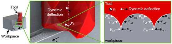
Figure 1.
Working hypothesis of the developed tool stabilization concept [5].
1.3. Distinction from the State of Research
From the previous results, it also remains unclear which specific design characteristics of the functional structures affect the tool stability behavior and within which process parameter configurations the highest potential is enabled. The investigations in this paper therefore initially focus on the question of which geometrical influences have an impact on the efficiency of the structure elements in order to design an optimized structure design. In a second step, the intention is to identify a process parameter range in which the tool concept can be applied efficiently. In consideration of the high adhesion tendency in aluminum cutting, the wear development of the structure elements and their effects on the stabilization potential will be examined at the end of the investigations.
2. Materials and Methods
In the following sections, the experimental setup and methods of these investigations are described in detail. At first, an overview of the experimental setup and the applied measurement tools is given, including the utilized specimens and the experimental procedure. Subsequently, the preparation method of the functional structured tools and their associated machining setup are presented.
2.1. Workpiece Material
EN AW-7075–T651, an aluminum alloy that is considered representative of aluminum machining in the aerospace industry, was used for the test samples. The material has a high strength required in this sector and is easy to machine, which is highly relevant in terms of typical material removal rates of up to 95% [65]. The test specimens are roll-formed sheets measuring 69 × 69 × 20 mm3, which have retained both their high hardness and high corrosion resistance as a result of heat treatment (T651). Table 1 lists mechanical properties and the detailed composition of the material.

Table 1.
Mechanical properties and chemical composition percentage of the material EN AW-7075; T651.
2.2. Experimental Setup
Ramp milling tests were carried out to investigate numerous influences on the stability behavior of the presented tool concept and for its further development. In Figure 2, an overview of the used five axis milling machine DMG MORI DMU 50 evolution II with the installed experimental setup including the measurement technology is given.
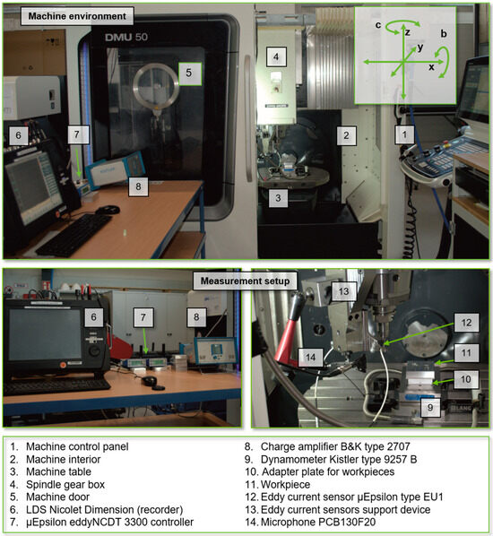
Figure 2.
Experimental setup installed on a DMG MORI DMU evolution milling machine.
A linear successive increase in the cutting depth ap, as practiced in ramp milling experiments, allows the determination of the stability boundary. In an ideal scenario, the workpiece surfaces are affected by chatter marks when instability occurs in the milling process [66]. In addition to the geometric verification of the stability limit using the workpieces, an experimental setup was designed to support a comprehensive process analysis using process measurement technology. Eddy current sensors were installed in the direction of the X and Y axes using a rigid support device attached to the spindle frame. The distance between the sensors and the tool shank could thus be measured during the milling process, which can serve as an indicator of any tool deflections that occur when instability arises. Furthermore, a microphone for audio measurements was installed in the machine interior to detect potential chatter frequencies. The experimental setup was supplemented by a force dynamometer, as shown in Figure 2, to detect the process force components acting in the x-, y- and z-direction of the workpiece coordinate system. The data of the force components were recorded with a sample rate of 100 kHz and were analyzed using the software application NI DIADEM 2021 (v. 21.0.0f8135, National Instruments, Austin, TX, USA). An adapter plate with centering pins was installed on the force dynamometer to clamp the workpieces.
Figure 3 illustrates the used clamping setup and provides a specific view of the engagement situation between tool and workpiece during the milling tests. In order to ensure identical conditions for all ramp milling tests, the test specimens were milled at right angles and to the same dimensions beforehand. In addition, they were provided with a drilling pattern to enable repeatable, centered placement and fastening on the force dynamometer. Thanks to the pinning, all test specimens share the same workpiece origin, meaning that a probing process was only necessary once. This was also a basic requirement for carrying out the large number of ramp milling tests, as changing the tool holder before each milling test would have resulted in a recalibration of the eddy current sensors. Due to the workpiece preparation, it was also possible to carry out ramp milling tests on all four workpiece sides, as suggested below in Figure 3.
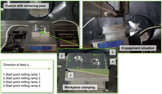
Figure 3.
Fixture, workpiece clamping and engagement situation.
As both geometric and technological influences are to be investigated as part of the milling experiments, milling tools with different structure specifications are used. After each tool change, therefore, it must be ensured that the tool cantilever length remains identical. The length changes resulting from the micro-structuring are assumed to be negligible with regard to the dynamic tool behavior. A hydraulic chuck made by Schunk with an adjustment screw was therefore used to precisely align the tool length. This enables a precise cantilever length alignment. In addition, the experimental setup used allows the HSS tools to be clamped and unclamped without affecting the calibration of the eddy current sensors.
2.3. Preparation of the Structured Flanks of the Milling Tools
HSS end mills with a diameter of 8 mm were used in these investigations to simplify the application of functional microstructures on the flanks of the minor cutting edges. In comparison to the investigations by Baumann et al., milling tools with a higher cutting edge length of 19 mm were used in order to facilitate and investigate unstable process behavior (Table 2).
Table 2.
Tool holder and dimension of HSS milling tools.
The three most suitable methods for inserting functional microstructures on cutting tools are electrical discharge machining, microlaser ablation and micro-milling [56]. Micro-milling was selected as the structuring method in these investigations with regard to the structure and tool shapes to be varied. In addition to its high flexibility, this method also proves to be more efficient than the other two methods in terms of the high ablation rate that can be achieved.
A Kern HSPC 2522 micro-milling machine (Kern Microtechnik GmbH, Eschenlohe, Germany), maximum spindle speed of 50,000 rev/min and positioning accuracy of ±0.001 mm, was used. Micro-ball end milling tools, with diameters of 0.2 mm, were used at a cutting speed of approx. 28 m/min. As shown in Figure 4, the clamping of the HSS-milling tools was realized using a hydraulic chuck.
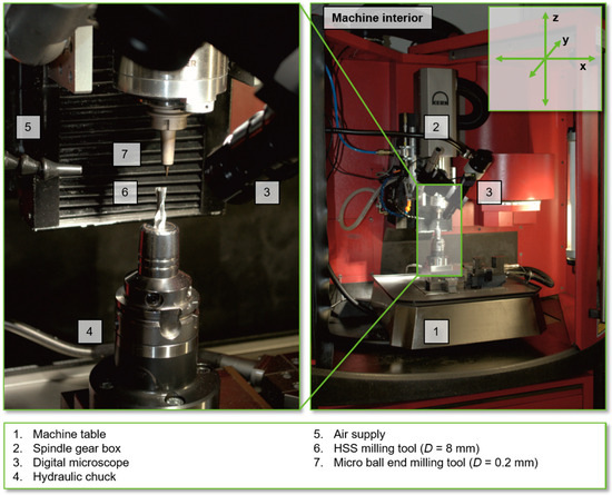
Figure 4.
Setup for the micro-structuring process of HSS milling tools.
Figure 5 illustrates the evolution of HSS tools from the manufacturer’s state to the fully prepared structured tool. The angle between the main and minor cutting edges of the HSS tools is less than 90° in the factory state. As a result, the minor cutting edges of the tools to be structured have a radial incline to the cutter center. Before the circular arc structures were produced, a chamfer was therefore applied to the flanks of the minor cutting edges in order to subsequently ensure the identical depths of the structure elements.
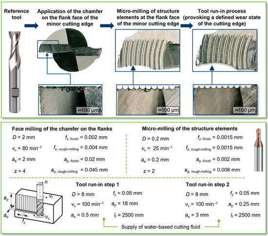
Figure 5.
Evolution of the HSS tools with applied structure elements.
In order to reduce the risk of chip locking between micro-milling tools and HSS tool surfaces, a compressed air supply was used during the structuring process. This was also intended to ensure cooling of the micro-milling tools to minimize wear. In order to achieve comparable depths of the structure elements on the HSS tools, the structuring process was divided into a roughing and a finishing section. These were implemented with separate micro-milling tools in order to minimize the influence of tool wear during the production of the final structure dimension.
Potential wear on the HSS tools has to be taken into account with regard to possible influences on the test results. In order to exclude wear-dependent variations in the engagement conditions in the ramp milling tests as far as possible, the HSS test tools were subjected to a running-in process after the structures were applied. As shown schematically in Figure 5, a defined, respectively leveled wear condition of the cutting edges was applied in two separate sub-running-in processes for the circumferential cutting edges and the structured flank faces. A water-cutting fluid based on ECOCOOL TN 2530 oil (FUCHS) was used during these processes. Based on Baumann’s investigations on wear development with regard to this tool concept, a defined feed path length of lf to be covered was determined. The milling path of lf = 2500 mm for each sub-run-in process was based on Baumann’s investigations for comparability. These showed that a running-in process of the structured HSS milling tools is important in order to ensure constant test conditions [5].
The length of the applied structure elements basically depends on the shape of the chamfer on the flank face of the HSS milling cutter, as the length of the structure elements correlates with the length of the chamfer. The deeper the chamfer is attached to the corresponding milling tool, the longer it is. In this context, the term “chamfer depth”, dch, was introduced as part of the present investigations. This characterizes the depth dimension at which a fictive sectional plane intersects the unmodified HSS milling tools in order to produce the resulting chamfer on the flank face of the minor cutting edge (Figure 6).
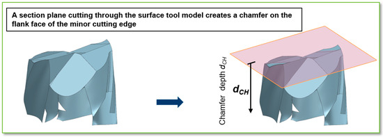
Figure 6.
Emergence principle of the chamfer of the flank face on the minor cutting edge.
3. Results
3.1. Optimization of the Structured Flank Face Shape of the Minor Cutting Edge
In order to optimize the cutting edge shape of the structured milling tools, three major geometric properties of the structure elements were varied and investigated. In the first step, the influence of the structure elements length on the stability limit was focused. It was also examined whether the radial position of the outer structure element had an impact on the tool stability behavior. Finally, this part of the investigation was complemented by varying the number of structure elements.
3.1.1. Variation in the Applied Structure Element Length
Due to the shape of the tool, with the minor cutting edge descending towards the milling cutter center and the existing helix angle of λ = 30 °, there is no linear relationship between the chamfer length and the chamfer depth dch. This also leads to the fact that the present structure elements of a cutting tool differ in length across the radius. For this reason, a chamfer depth dch was determined for each structured tool in this first series of tests as a function of the arithmetic average length of the structure elements, in accordance with Table 3.
Table 3.
Tool specification in terms of the length of structure elements dependent on the depth of the applied chamfer.
By means of a stability lobe diagram and accompanying experimental milling tests, a reference process at a stable spindle speed and the milling parameters listed below in Figure 7 were defined in preliminary investigations. With this process parameter configuration, a stability limit of ap,crit = 4.59 mm for the reference process with an unstructured HSS milling cutter was achieved. For the structured tool SL5 with the highest depth of the chamfer dch, this frequency even seems to disappear completely in the process area before the stability limit ap,crit is reached. This may indicate that externally excited vibrations can be damped as a direct result of the applied structure elements. It is clearly evident from the results of this test series shown in Figure 7 that a successive increase in the stability limit for this type of tool can be achieved with an increasing structure length.
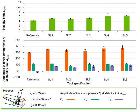
Figure 7.
Stability limits and amplitudes of force componentns due to the varied chamfer depth.
For the SL5 tool with the largest chamfer depth of dch = 0.4 mm, there is a maximum stability limit of ap,crit = 6.59 mm, which corresponds to an increase of 44% compared to the reference process and 30% compared to the process with the SL2 tool (ap,crit = 5.08 mm). Contrary to this trend, the stability limit for the SL1 tool is slightly higher at ap,crit = 5.32 mm, despite the lower depth of the chamfer dch. In this context, however, it should be mentioned that all 10 structure elements are first fully developed at the chamfer depth of the second tool SL2 at dch = 0.1 mm. At smaller chamfer depths, the chamfer is not wide enough. Therefore, the deviation of the trend for tool SL1 is only of limited significance in this context. In the comparison (Figure 7) of the stability limits achieved and the amplitudes of the process force components, it can be seen that cutting forces occur predominantly in the Fx and Fy directions, which shows a strong correlation to the trend of the achieved stability limits.
Compared to the reference process, there is a reversal trend with regard to the force amplitudes in the Fz direction. The larger contact surfaces that occur as a result of the applied structures could be a reason for the higher normal forces, meaning that higher frictional forces may occur as a result. These in turn could be an indicator of potentially higher process damping.
3.1.2. Influence of the Radial Position of the Initial Structure Element of the Flank Face on the Stability Limit
As depicted in Figure 5, it is obvious that a specific cutting edge shape is created on the outer tool radius as a result of the micro-milling preparation process. Based on this background, the investigations in this section focus on the objective of using a radial change in the position of the outermost structure elements to achieve a constructive stabilization and thus also a process-stabilizing effect.
For this investigation, all structured tools were provided with a chamfer depth of dch = 0.23 mm, as shown in Figure 8 and Table 4, based on the tool specification SL3 of the previous test series. The structure radius of rs = 100 µm was used as a measure of the radial displacement. The basic idea of the SL3 – rs/4 tool is to create a flat section on the outer flank by radially displacing it inwards. The other two structured tools take the opposite approach. In this case, an opening of the flanks of the outermost structure element shall be realized by an outward radial displacement in order to obtain a defined corner of the cutting edge.
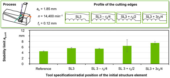
Figure 8.
Stability limits due to the varied radial position of the initial engaging structure elements.
Table 4.
Tool specification in terms of the radial position of the initially engaging structure element.
The resulting force components and the stability limits achieved in ramp milling tests with the tool modified according to the first approach (flat profile on the outer flank) show a significant reduction in the achievable process limits. In contrast, the second approach shows clear potential for improvement. In the case of the more performant structured tool, a maximum arithmetic mean value of ap,crit_SL3+3 rs/4 = 7.47 mm was achieved in the ramp milling tests. This corresponds to an increase in the limit cut depth compared to the structured tool SL3 of Δap,crit = 1.89 mm or an increase in stability of 34%. It should be noted, however, that the high standard deviation that occurs in the ramp milling tests with the tool of the lower radial element displacement (SL3 + rs/2), cannot be explained. In this context, due to the small number of two repetitions per ramp milling test, it is not obvious which of the two approaches is the more efficient one. As a result of the low standard deviations occurring in the ramp milling tests, the greatest stabilization potential in terms of the radial position of the initially engaging structure element is assumed for the structured tool SL3 + 3rs/4 in the following considerations.
3.1.3. Influence of the Number of Applied Structure Elements on the Stability Limit
The experimental investigations in this section are based on previous studies by Jaquet et al., which were carried out on the basis of theoretical considerations for the orthogonal cutting process [67]. They considered material removal and the resulting workpiece surface depending on the tooth feed-related overcuts during the interaction between the structured cutting wedge and the workpiece. These considerations were continued in experimental investigations in the orthogonal cutting process and then transferred to the rotational milling process in simulative milling investigations. According to the results, after a certain number of overcuts on the workpiece surface, there was no more workpiece material left in the milling process that could interact with the functional structures on the flanks of the minor cutting edges. For the milling process and the design of the tool concept, it can be deduced that only a number of four structure elements are necessary for a process stabilizing support effect, since no further support effect is generated from the fifth structure element onwards. Within the framework of this series of investigations, it is therefore necessary to verify whether the results assumed for a highly idealized milling process can be transferred to a real milling process. This means that, starting from the outer radius, no significant further increase in stability can be achieved from a certain increase in the number of elements to the tool center point.
As shown in Figure 9, the results of the present physical ramp milling experiments deviate from the conclusions of the previously mentioned theoretical investigations. There is a clear systematic for the stability limits achieved and the amplitudes of the Fx cutting force components, which, contrary to assumptions, do not follow a trend but reveal a complex periodic correlation. Starting with a tool of one structure element per cutting edge (SL1), there is a local maximum of the stability limit. Subsequently, the stability limit in the ramp milling tests decreases successively with an increasing number of functional elements down to a local minimum of ap,crit_SE5 = 5.54 mm, which nearly represents the stability limit of the reference process. With a further increase in the number of elements, the stability limit initially increases slightly in the milling experiments and then rises rapidly from the tool configuration with seven structure elements before the absolute maximum of the test series of ap,crit_SE9 = 8.19 mm occurs using nine structure elements (SE9). With the last structured tool (SE10), which corresponds to the tool configuration SE3 from the previous test series, the process limit decreases abruptly to a local minimum of ap,crit_SE10 = 5.77 mm. In this test series, the conclusion of the first test series on the analysis of the chamfer depth dch is confirmed by the fact that the cutting force component Fx, which mainly acts in the feed direction, correlates predominantly with the development of the stability limit.
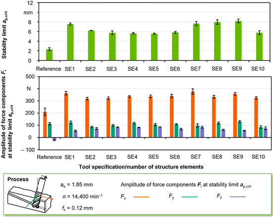
Figure 9.
Stability limits and amplitude of the force components due to the varied number of structure elements.
Despite the available results, the assumptions of the preliminary investigations seem reasonable, indicating that interaction volume is only present up to a certain number of overlaps, which contributes to process stabilization. However, on the basis of the explained results, it can be stated with certainty that in the case of an existing threshold value, where no further increase in stability takes place, this would be above nine structure elements.
In preliminary tests to the experimental investigations on the influence of the chamfer depth dch, plateau tools were used which possess equivalent flank chamfers to the test tools SL1–SL5. After a short period of utilization in ramp milling tests, these were affected by such massive wear that a further application is not considered reasonable from a technological point of view. However, the preliminary investigations have shown that an increase in stability in the milling process can be achieved simply by increasing the chamfer surface of the flanks. Thus, the decreasing stability limit with an increasing number of structure elements can possibly be explained by the fact that both the surface of the chamfer and the stabilization potential decrease successively up to tool configuration SE5. This therefore indicates that increasing the number of structure elements has two opposing effects on the process stability behavior. On the one hand, the increase in the number of acting elements itself appears to have a process-stabilizing effect, whereas the corresponding reduction in the unstructured chamfer surface of the flanks could reduce the stabilization potential. Starting from the tool configuration with six structure elements SE6, the positive effect of the increased number of elements appears to predominate due to the trend reversal of the stability limits achieved.
The analysis of the development of cutting force components in the ramp milling process supports the basic assumption that the increase in structure elements has a stabilizing effect on the process. Two effects can be seen from the results in Figure 10 with regard to the FX cutting force components. On the one hand, there is a flatter and almost linear gradient until the unstable process part is reached in the case of structured tools compared to the reference process. On the other hand, the corresponding gradient in the reference process has a more degressive gradient. The slower increase in force could be an indicator that lateral forces are actually absorbed by the functional elements by using the structured tools, thus enabling a shift in the stability limit to higher cutting depths. A second effect that could be identified relates to the fact that the signals of the FX cutting force components in the unstable part of the reference process are strongly superimposed by vibrations. This effect of vibration superimposition decreases significantly with an increase in the number of structure elements and almost disappears with the SE10 tool specification. Therefore, the stability limit of this tool configuration may be estimated to be higher than the results achieved in the ramp milling tests suggest.
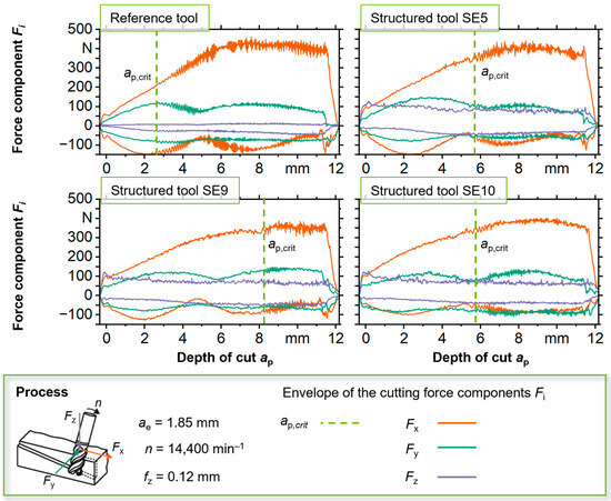
Figure 10.
Development of forces due to a varied number of structure elements.
The decrease in the performance of Δap,crit = −2.42 mm compared to the tool specification of SE9 is probably a result of the fact that the lateral engagement width of ae = 1.85 mm in the milling process of the internal structure element, as illustrated in Figure 11, results in a one-sided load on the structure arc. As a result, a lower lateral support effect can be assumed. Based on this information, it can be concluded that in order to optimize the structure tool concept, not only should the design of the cutting edge shape but also the lateral engagement width ae be matched to the number and total width of the structure elements.
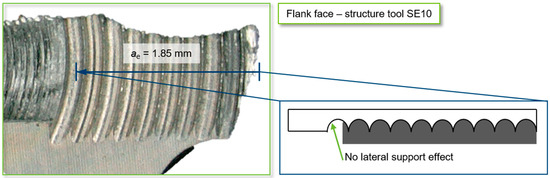
Figure 11.
Theoretical contact of the structure elements with the surface material depending on the selected lateral engagement ae and the number and width of the structure elements.
3.2. Function of the Structure Tool Concept under Varied Process Parameters
A constant operating point was selected in the experimental studies to achieve comparable process conditions and a focused investigation of the influence of the tool modification. In order to further characterize the influence of varying process parameters on the tool concept, investigations were carried out in accordance with the parameter range scheme shown in Figure 12. Following the scheme in Figure 12, four different spindle speeds were combined with the selected range of tooth feeds in the ramp milling tests of the present investigation. By doing so, each possible parameter combination was repeated four times, with regard to the statistical certainty of the experimental results. Thus, by using two tool configurations, 160 ramp milling tests were carried out in total.
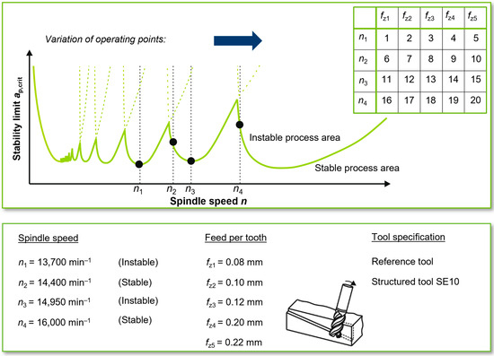
Figure 12.
Scheme of the process stability lobe diagram and process parameter variation.
Besides testing various stable and unstable spindle speeds, different tooth feeds are of particular interest. In the theoretical and simulative investigations by Jaquet et al. [67], it turned out that at tooth feeds of 120% of the structure arc width, optima occur with regard to process stabilization potential. In relation to the existing structure widths of ws = 200 μm, the optimum tooth feed would therefore be a value of fz = 0.24 mm. However, preliminary tests with the reference tool showed that stable processes can only be realized in ramp milling tests with a radial engagement width of ae = 1.85 mm up to a tooth feed of fz = 0.22 mm, as otherwise the cutting force components are too high. Therefore, no optimum stabilization potential could be demonstrated for a tooth feed of fz = 0.24 mm.
Figure 13 provides an overview of the stability limits achieved in the present investigations. A technologically relevant range and a technologically irrelevant process range can be identified for the selected tooth feed rates. The second-mentioned tooth feed range for both tool specifications used (SE10 and reference) is characterized by stability limits achieved in the ramp milling tests, which are between 30 and 40 percent of the technologically relevant tooth feed range. Within the relevant tooth feed range, at a constant engagement width of ae = 1.85 mm, amplitudes of between 300 and 400 N occurred for the process-dominating force component in the Fx direction, when the stability limit was reached. In contrast, these force amplitudes occur in the milling processes in the technologically irrelevant tooth feed range with a factor of 2–2.5 or with maximum forces of approx. 830 N. This implies the conclusion that only a very limited lateral support effect is provided by the functional structure elements due to the excessive process forces.
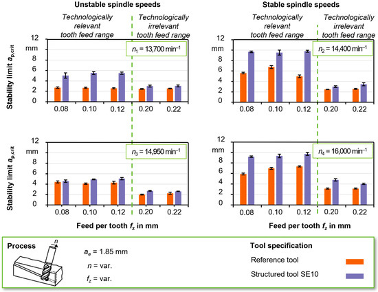
Figure 13.
Stability limits due to varying process parameters.
In preliminary studies for these experimental investigations, a parameter range of stable and unstable spindle speeds was determined, using a stability diagram based on the tool natural frequencies and additional milling tests with a reference tool. In all ramp milling tests an increase in stability could always be detected on an arithmetical average by utilizing the structure tool configurations compared to the reference tool used.
However, when differentiating between stable and unstable speeds, it can be seen that when using the structured tools in the stable speed range (n2, n4), the stability limits tend to be higher compared to the reference tools. In addition, the stability limits achieved by the structured tools in the ramp milling tests with the unstable speed n3, even in the technologically relevant tooth feed range (fz = 0.08–0.12 mm), are approximately the same as those of the reference process. This indicates that the stabilization effect of the structure tool concept tends to be higher the more stable the operating point is selected. Furthermore, certain unstable operating speeds appear to create process conditions at which the stabilization potential is almost completely eliminated.
Stability limits with similar levels occurred at all applied spindle speeds over the range of the three technologically relevant tooth feeds. Despite the similar levels, the maximum stability limit could be verified for the tooth feed of fz = 0.12 mm for all selected spindle speeds. The maxima of ap,crit_max_n2 = 9.68 mm and ap,crit_max_n2 = 9.74 mm occurred for these two stable spindle speeds. Thus, the maxima of the stability limit was detected for exactly half of the supposed tooth feed optimum of fz = 0.24 mm. This corresponds exactly to an integer divisor of 120% of the applied structure arc width of bs = 200 μm. According to the simulation-based experiments of Jaquet et al. [67], this confirms the assumption that the stabilization potential of the presented tool concept can be maximized with certain size relations between tooth feed and applied structure width of:
3.3. Wear Development of Structured Milling Tools in the Cutting of Aluminum
Baumann’s investigations have already shown that the stability behavior of structured HSS tools depends on the development of wear. Adhesive wear mechanisms in particular appear to exert a major influence [5]. The results show that after a certain process time, the stability limits can decrease before the structured tools are subject to a kind of recovery effect after a further process time. This wear-related positive effect on the achievable process limit and its time variant dependency is characteristic for aluminum milling processes with HSS tools [68]. Particularly in the case of the reference tools used without structure elements, this not only led to an increase in the stability limit but also to an increase to a higher stability level. However, the tools used remained at this level until the experimental investigations were discontinued. For the structure specification, also used in the present investigations, instead, a constantly stable process was present, so that in this specific case, no statements could be made about the influence of tool wear. Consequently, no wear-related process limit of the milling tools could be determined regardless of the tool specification used.
The present tool wear investigations therefore focused on two questions. On the one hand, the extent to which the tool run-in behavior should be taken into account should be investigated and, on the other hand, a wear-related process limit for the tool concept used should be determined. In addition to a reference tool, two structured milling tools of different types were used (Table 5). The tool specification SL3 is very close in design to the structured tool used in the wear investigations of Baumann et al. [5]. The second tool specification (SL5 + 3rs/4), on the other hand, represents an attempt to combine the most optimal design features in one tool for the geometric influencing features investigated so far (structure length, position of the initial structure element, number of structure elements). In order to take into account the tool run-in behavior with respect to the recovery effect, a tool run-in process was dispensed before the previous ramp milling tests of the present investigations were carried out. In order to be able to detect the aforementioned recovery effect, short wear intervals with a feed path length of lf = 2000 mm were selected at the beginning of the wear tests, as can be seen in Figure 14, which were then successively doubled to an interval size of lf = 64,000 mm. After a feed path length of lf = 128,000 mm, the size of the further milling intervals remained constant until the end of the test. Following the defined feed path length intervals, one ramp milling test was carried out for each tool type.
Table 5.
Applied tool specifications in the experiments on the tool wear behavior.
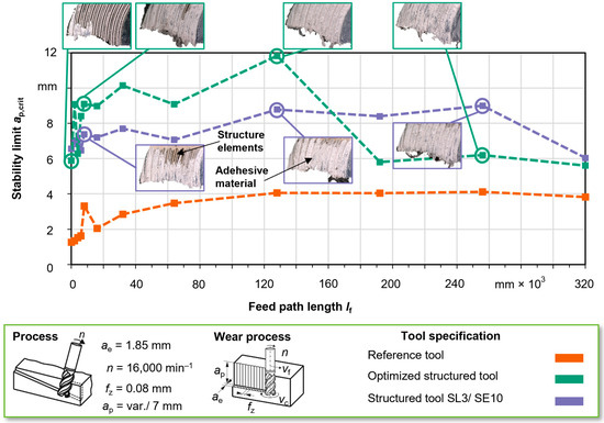
Figure 14.
Wear-related development of the stability limit depending on the tool specification.
3.3.1. Wear-Related Process Limits of the Tool Concept
For the reference tool used, small successive increases in the stability limit initially occurred before these rose rapidly to a value of ap,crit_8000 = 3.7 mm at a feed path length of lf = 8000 mm compared to the starting value of ap,crit_0 = 1.67 mm. After the next wear interval, a sudden decrease in the stability limit was again recorded. Subsequently, after the following wear intervals, a gradual increase in the stability limit up to a feed path length of lf = 128,000 mm was observed. This wear level with a stability limit of approx. ap,crit = 4 mm remained constant in the ramp milling tests as a result of the subsequent wear intervals until the end of the test.
For the first wear intervals, a characteristic of the wear-dependent stability limit, which is characterized by increases and decreases, also occurred with the two structured tools. However, in contrast to the reference tool, the development of the stability limit is subject to several jump-like rise and fall cycles up to the feed path length of lf = 8000 mm. Afterwards, the wear-related development of the stability potential of the structured tools continues to be subject to alternately increasing and decreasing characteristics. Both tool specifications reach their maximum stability after a feed path of lf = 128,000 mm. Their levels of ap,crit_max_SL5+3rs/4 = 11.82 mm and ap,crit_max_SL3 = 8.78 mm, on the one hand, illustrate the potential of the tool concept to increase stability compared to the reference tool used. On the other hand, the results confirm that the combination of the optimized structure design features can achieve a further increase in performance compared to the originally used structured tool specification.
The optimized structured tool shows an increase in the stability of between 25% and 34% compared to the initially used structured tool SL3 up to a feed path length of lf = 128,000 mm. While the stability limits occurring in the processes of the SL3 tool remain within the maximum range up to a feed path length of lf = 256,000 mm, the stability limit for the optimized structured tool decreased after a feed path length of lf = 128,000 mm. After the next interval, a relative stability minimum of ap,crit_min_SL5+3rs/4 = 5.8 mm occurs, which the stability limit levels out around until the end of the experimental wear test. This wear-induced loss of stability can be interpreted as the end of the tool operating life due to the high decrease in performance. For the tool specification SL3, this effect does not occur until after the tool life of lf = 320,000 mm.
The observation of optical images from the wear investigation presented (Figure 14) supports the impression that adhesion processes are to a large extent responsible for the end of the service life of the structured tools investigated. From the moment the stability limit is reached, the structure channels of both tool specifications are completely covered with workpiece material from the cutting edges to the flanks. In addition, the structure elements of both structured tools already exhibit clearly visible adhesions after the first interval. In order for the underlying hypothesis of the tool concept to occur, workpiece material must be able to slide through the structure elements in order to achieve a stabilizing effect as a result of friction and lateral support. Following this guiding principle, it can therefore be assumed that the deposits adhering to the structured surfaces could be displaced by subsequent workpiece material up to a certain stage of wear. Conversely, this could mean that the wear-related application limit occurs in the state of the structured cutting edges in which displacement by subsequent workpiece material is no longer possible. As a result of the high adhesion tendency, the structure elements are almost completely covered by adhering workpiece material.
With the wear-related tool life limit occurring considerably later with the SL3 tool specification compared to the optimized structured tool, the question of a correlation between the tool life and the structure length arises. On the one hand, it was demonstrated in the presented first series of tests that an increase in the length of the structure elements results in an increase in the stabilization potential. With regard to wear, however, the results of the present wear investigation indicate a performance-reducing influence of the structure element extension. It is possible that the detachment of the adhering workpiece material on the structure elements is favored by a shorter structure element length. In this context, a qualitative optical analysis of the tool surfaces shows that the tool structures of the optimized structured tools are completely covered at a lower wear stage. As a result, it can be deduced that the displacement of the adhesive deposits by subsequent workpiece material is possible over a longer service life for the structured tools with shorter structure elements than for the optimized structured tool. This would explain why the SL3 tool has a lower possibility of increasing the stability limit compared to the optimized structured tool but is applicable over a longer process window in the peak of its own stabilization optimum.
3.3.2. Potential of Preconditioning of the Structure Tool Concept
Based on the results of the wear tests, an optimal, wear-dependent process window crystallized for the tool concept, in addition to the limit of the tool life, for both structured tool specifications. In this respect, it is unclear where exactly the stability limits occur, as the wear intervals were chosen too high in order to be able to precisely determine the optimum process window. However, this can at least be narrowed down to a rough approximation. The start of the optimum process range for both structured tool specifications is estimated to begin after a feed path length lf = 64,000 mm. The optimum process window for the optimized structured tool reaches approximately up to a tool life in the range of lf = 128,000 mm, whereas for the structured tool specification SL3 there is an optimum application range up to a tool life of approximately lf = 256,000 mm.
Within these process windows, the stability limit can be increased by up to 200% compared to the reference tool used. This is an important indication that the tool run-in behavior is a decisive factor for the performance of the investigated tool concept. It therefore appears that the running-in process, which preceded the majority of the investigations presented here, in order to produce defined and comparable wear conditions, resulted in an optimization of the cutting edges. First of all, the positive effect can be seen in the removed burr that remains on the structure elements in the initial tool state as a result of micro-milling (Figure 5). In this regard, it should be noted that the manufacturing process of the structure elements by micro-milling is unsuitable for industrial application due to time constraints and the high burr formation. In the present case, however, it was highly suitable in terms of the variety of structures to be produced and the associated demands on process flexibility.
In addition to the positive effect of the removed burr, it can be assumed that wear related effects like an increased rounding of the cutting edges, increasing the width of flank wear marks and the resulting flank chamfers behind the cutting edges cause a change in the contact conditions between the tool and the workpiece surface. These changes usually result in increased damping behavior and thus increase the stabilization potential. In future work, it is therefore of interest to determine which explicit geometric attributes such an optimized cutting edge shape should have [69,70]. Furthermore, the question arises which manufacturing process can be used to achieve an optimum cutting edge shape for industrial applications. In this respect, it would be expedient to integrate a method for cutting edge preparation into the manufacturing process of the structured tools, which substitutes the complex procedure of the tool run-in process. Cutting edge preparation methods are considered to be efficient for eliminating burr formation as a result of tool manufacturing processes. They are also suitable for increasing cutting edge stability with regard to the previously addressed adhesion behavior. Furthermore, it would also make sense to use such preconditioning as a basis for suitable coating technologies in order to increase its wear resistance in addition to optimizing the cutting edge shape [71].
4. Conclusions
In these investigations, the potential of milling tools with structure elements on the flanks of the minor cutting edge to reduce tool deflection in aluminum milling processes was demonstrated. Based on the original structure tool concept of Baumann et al. [5], an optimized structured tool with regard to the structure shape could be developed in order to maximize the process stability.
4.1. Key Design Features and Optimized Structured Milling Tool
In this respect, the direct influence of the following three specific geometric features of the structure element shape on the height of the stability limit ap,crit was demonstrated in ramp milling tests with aluminum alloy EN AW-7075-T651:
- The length of the applied structure elements has an increasing effect on the stability limits ap,crit. The maximum possible structure length that could be applied to the HSS milling tools enabled an increase in the stability limit ap,crit of 44% compared to the reference tool.
- The radial position of the structure elements of the flank faces on the outer tool radius influences not only the process stability but also the integrity of the cutting edge shape. The investigations have shown that the outer tool radius of an HSS milling tool should not start with the profile peak of a structure element in order to prevent its premature break-out. On the other hand, the authors recommend an open characteristic of the outer structure element when using the structure tool concept. Compared to the originally developed structure tool concept, this also enables an increase in the stability limit ap,crit by up to 34%.
- The number of applied structure elements on the flanks of the minor cutting edges has an effect on the process stability to the extent that an increase in this number should be accompanied by an increase in stability. In addition, the test results indicate that the structured cutting edge width resulting from the number of elements applied should correspond exactly to the radial engagement ae in order to exploit the maximum potential for increasing stability.
With regard to the number of applied structure elements, it should be critically noted that the possibility of increasing the process stability is limited by the fact that the process-stabilizing effect does not occur linearly as the number of elements increases. Due to the geometric changes in the shape of the cutting edge as a result of the increased number of structure elements, the ramp milling tests revealed an anticyclical progression of the stability limits achieved, which is based on opposing influences. Local minima and maxima of the achieved stability limit ap,crit occurred. From six structure elements onwards, the ramp milling tests showed a successive increase in the stability limit ap,crit, which culminated in an absolute maximum of the test series at nine used structure elements. In this context, the hypothesis from previous research work that there is no further increase in stability above a number of four structure elements has not been confirmed. Future research should clarify whether this effect occurs above the maximum number of ten structure elements used here.
4.2. Technological Relevant and Suitable Process Parameter Range
Furthermore a specific process parameter configuration for the presented tool specifications to optimize the stabilization potential in terms of the reachable stability limit ap,crit was identified. Therefore, a high number of ramp milling tests was carried out to cover a process parameter range between five different feeds per tooth fz combined with four different operation points representing two stable and two instable spindle speeds. For the utilization of the presented structure tool concept in milling processes with aluminum alloy EN AW-7075, the following recommendations could be made:
- Regardless of the spindle speed used, tooth feeds of fz = 0.2 mm and higher can be assumed to be technologically irrelevant. In this tooth feed range, no significant increase in stability can be expected from the tool concept presented.
- In contrast, a significant stabilization potential was demonstrated in a technologically relevant tooth feed range (fz = 0.08 mm–0.12 mm). The optimum stabilization potential occurs at a tooth feed of fz = 0.12 mm. In this respect, the occurrence of the optimum coincides with the assumption from previous studies, which predicts optimum stability in the event that the value of the tooth feed fz corresponds to 120% of the structure element width bS used or an integer divisor of this value
- Although a stabilization potential could be demonstrated at an operating point with an unstable speed, it should be noted that a stabilization effect of the structure tool concept may be completely absent if unfavorable unstable operating speeds are used.
4.3. Wear-Dependent Cutting Edge Shape in Terms of Stability Optimum
In addition to geometric and process parameter-based effects, the wear-related influence on the effectiveness of the tool concept presented was also considered. Within the scope of the wear tests, a structured tool with an optimized cutting edge shape was used, among other tools. In this context, it was demonstrated that an increase in the stability limit of up to 200% can be achieved compared to the reference tools used, taking into account all geometric influencing factors of the cutting edge shape.
In this context, it should be noted that this optimum increase in stabilization is highly dependent on the wear development of the structured cutting edges. The test results show that the maximum performance of the structured tools can only be achieved at certain stages of wear. This fact indicates that the tool run-in practiced in majority of the presented studies is essential in order to exploit the potential of the structure tool concept.
The investigations have confirmed that adhesive processes represent the main cause of the wear-related tool life for the structured tools, particularly in the context of machining aluminum. In this respect, future research work should focus on a suitable method for cutting edge preparation, which on the one hand enables the time-consuming tool running-in process to be substituted and on the other hand provides a more adhesion-resistant functional surface compared to micro-milled structure elements. With regard to the wear-related end of tool life and, in particular, the issue of adhesive effects, future work should focus on the utilization of coatings. Assuming that the process-stabilizing effect in the sense of the initial hypothesis of the structure tool concept is maintained, coating technologies might enable an additional increase in stability as well as the transfer of the concept to solid carbide tools for industrial applications.
Author Contributions
Conceptualization, R.I.E.S., J.B., R.G.C. and D.B.; methodology, R.I.E.S., J.B., R.G.C. and D.B.; validation, R.I.E.S., J.B. and D.B.; formal analysis, R.I.E.S.; investigation, R.I.E.S. and R.G.C.; resources, D.B.; data curation, R.I.E.S.; writing—original draft preparation, R.I.E.S. and J.B.; writing—review and editing, J.B. and D.B.; visualization, R.I.E.S.; supervision, D.B.; project administration, D.B.; funding acquisition, D.B. All authors have read and agreed to the published version of the manuscript.
Funding
This research was funded by the German Research Foundation (DFG, Deutsche Forschungsgemeinschaft)—project number 426468684.
Data Availability Statement
The data presented in this study are available on request from the corresponding author.
Conflicts of Interest
The authors declare no conflicts of interest.
References
- Quintana, G.; Ciurana, J. Chatter in machining processes: A review. Int. J. Mach. Tools Manuf. 2011, 51, 363–376. [Google Scholar] [CrossRef]
- Weck, M.; Brecher, C. Werkzeugmaschinen 5, 7th ed.; Springer: Berlin/Heidelberg, Germany, 2006; ISBN 978-3-642-38748-7. [Google Scholar]
- Altintas, Y. Manufacturing Automation: Metal. Cutting Mechanics, Machine Tool Vibrations, and CNC Design, 2nd ed.; Cambridge University Press: New York, NY, USA, 2012; ISBN 978-1-107-00148-0. [Google Scholar] [CrossRef]
- Munoa, J.; Beudaert, X.; Dombovari, Z.; Altintas, Y.; Budak, E.; Brecher, C.; Stépán, G. Chatter suppression techniques in metal cutting. CIRP Ann. Manuf. Technol. 2016, 65, 785–808. [Google Scholar] [CrossRef]
- Baumann, J.; Krebs, E.; Biermann, D. Chatter avoidance in milling by using advanced cutting tools with structured functional surfaces. MM Sci. J. 2019, 4, 3019–3026. [Google Scholar] [CrossRef]
- Sellmeier, V. Über den Einfluss der Werkzeuggestalt auf die Dynamische Stabilität des Fräsprozesses. Ph.D. Thesis, Gottfried Wilhelm Leibniz Universität, Hannover, Germany, 26 June 2012. [Google Scholar] [CrossRef]
- Stone, B. Chatter and Machine Tools; Springer: Cham, Switzerland, 2014; ISBN 978-3-319-05236-6. [Google Scholar]
- Grabowski, R.; Denkena, B.; Köhler, J. Prediction of process forces and stability of end mills with complex geometries. Procedia CIRP 2014, 14, 119–124. [Google Scholar] [CrossRef][Green Version]
- Guo, Q.; Jiang, Y.; Zhao, B.; Ming, P. Chatter modeling and stability lobes predicting for non-uniform helix tools. Int. J. Adv. Manuf. Technol. 2016, 87, 251–266. [Google Scholar] [CrossRef]
- Comak, A.; Budak, E. Modeling dynamics and stability of variable pitch and helix milling tools for development of a design method to maximize chatter stability. Precis. Eng. 2017, 47, 459–468. [Google Scholar] [CrossRef]
- Niu, J.; Ding, Y.; Zhu, L.; Ding, H. Mechanics and multi-regenerative stability of variable pitch and variable helix milling tools considering runout. Int. J. Mach. Tools Manuf. 2017, 123, 129–145. [Google Scholar] [CrossRef]
- Otto, A.; Rauh, S.; Ihlenfeldt, S.; Radons, G. Stability of milling with non-uniform pitch and variable helix tools. Int. J. Adv. Manuf. Technol. 2017, 89, 2613–2625. [Google Scholar] [CrossRef]
- Iglesias, A.; Dombovari, Z.; Gonzalez, G.; Munoa, J.; Stepan, G. Optimum selection of variable pitch for chatter suppression in face milling operations. Materials 2019, 12, 112. [Google Scholar] [CrossRef] [PubMed]
- Sellmeier, V.; Denkena, B. Stable islands in the stability chart of milling processes due to unequal tooth pitch. Int. J. Mach. Tools Manuf. 2011, 51, 152–164. [Google Scholar] [CrossRef]
- Zhang, X.; Xiong, C.; Ding, Y.; Xiong, Y. Variable-step integration method for milling chatter stability prediction with multiple delays. Sci. China Technol. Sci. 2011, 54, 3137–3154. [Google Scholar] [CrossRef]
- Volokh, V.; Boulakhov, S.; Sharivker, L.; Zeidner, S.; Galipko, V. Chatter-Resistant End Mill. U.S. Patent 8,221,036, 17 July 2012. [Google Scholar]
- Merdol, S.D.; Altintas, Y. Mechanics and dynamics of serrated cylindrical and tapered end mills. J. Manuf. Sci. Eng. 2004, 126, 317–326. [Google Scholar] [CrossRef]
- Dombovari, Z.; Altintas, Y.; Stepan, G. The effect of serration on mechanics and stability of milling cutters. Int. J. Mach. Tools Manuf. 2010, 50, 511–520. [Google Scholar] [CrossRef]
- Denkena, B.; Léon, L.; Grove, T. Prozessstabilität eines kordelierten Schaftfräsers. Z. Wirtsch. Fabr. 2010, 105, 37–41. [Google Scholar] [CrossRef]
- Denkena, B.; Grabowski, R.; Krödel, A.; Ellersieh, L. Process stability of a novel roughing-finishing end mill. Prod. Eng. Res. Dev. 2020, 14, 395–405. [Google Scholar] [CrossRef]
- Suzuki, N.; Takahashi, W.; Igeta, H.; Nakanomiya, T. Flank face texture design to suppress chatter vibration in cutting. CIRP Ann. Manuf. Technol. 2020, 69, 93–96. [Google Scholar] [CrossRef]
- Seguy, S.; Insperger, T.; Arnaud, L.; Dessein, G.; Peigné, G. On the stability of high-speed milling with spindle speed variation. Int. J. Adv. Manuf. Technol. 2010, 48, 883–895. [Google Scholar] [CrossRef]
- Seguy, S.; Insperger, T.; Arnaud, L.; Dessein, G.; Peigné, G. Suppression of period doubling chatter in high-speed milling by spindle speed variation. Mach. Sci. Technol. 2011, 15, 153–171. [Google Scholar] [CrossRef]
- Zhang, H.; Ni, J. Internal energy based analysis on mechanism of spindle speed variation for regenerative chatter control. J. Vib. Control 2010, 16, 281–301. [Google Scholar] [CrossRef]
- Sahu, G.N.; Vashisht, S.; Wahi, P.; Law, M. Validation of a hardware-in-the-loop simulator for investigating and actively damping regenerative chatter in orthogonal cutting. CIRP J. Manuf. Sci. Technol. 2020, 29 Pt A, 115–129. [Google Scholar] [CrossRef]
- Möhring, H.-C.; Wiederkehr, P.; Lerez, C.; Siebrecht, T.; Schmitz, H. Case study 1.1: Identification and active damping of critical workpiece vibrations in milling of thin walled workpieces. In Intelligent Fixtures for the Manufacturing of Low Rigidity Components, 53rd ed.; Möhring, H.-C., Wiederkehr, P., Gonzalo, O., Kolar, P., Eds.; Lecture Notes in Production Engineering; Springer: Berlin/Heidelberg, Germany, 2018; pp. 3–23. ISBN 978-3-319-45290-6. [Google Scholar]
- Abele, E.; Dohnal, F.; Feulner, M.; Sielaff, T.; Daume, C. Numerical investigation of chatter suppression via parametric anti-resonance in a motorized spindle unit during milling. Prod. Eng. 2018, 12, 309–317. [Google Scholar] [CrossRef]
- Peng, Z.; Zhang, D.; Zhang, X. Chatter stability and precision during high-speed ultrasonic vibration cutting of a thin-walled titanium cylinder. Chin. J. Aeronaut. 2020, 33, 3535–3549. [Google Scholar] [CrossRef]
- Wan, S.; Li, X.; Su, W.; Yuan, J.; Hong, J. Active chatter suppression for milling process with sliding mode control and electromagnetic actuator. Mech. Syst. Signal Process. 2020, 136, 106528. [Google Scholar] [CrossRef]
- Wang, M.; Fei, R. Improvement of machining stability using a tunable-stiffness boring bar containing an electrorheological fluid. Smart Mater. Struct. 1999, 8, 511–514. [Google Scholar] [CrossRef]
- Ma, J.; Zhang, D.; Wu, B.; Luo, M.; Liu, Y. Stability improvement and vibration suppression of the thin-walled workpiece in milling process via magnetorheological fluid flexible fixture. Int. J. Adv. Manuf. Technol. 2017, 88, 1231–1242. [Google Scholar] [CrossRef]
- Sellmeier, V.; Denkena, B. High speed process damping in milling. CIRP J. Manuf. Sci. Technol. 2012, 5, 8–19. [Google Scholar] [CrossRef]
- Wöste, F.; Baumann, J.; Wiederkehr, P.; Surmann, T. Analysis and simulation of process damping in HPC milling. Prod. Eng. Res. Devel. 2019, 13, 607–616. [Google Scholar] [CrossRef]
- Wöste, F.; Platt, T.; Baumann, J.; Biermann, D.; Wiederkehr, P. Fundamental investigation on process damping potentials of cutting tools with flank face chamfers. CIRP J. Manuf. Sci. Technol. 2023, 47, 7–17. [Google Scholar] [CrossRef]
- Gao, J.; Altintas, Y. Chatter stability of synchronized elliptical vibration assisted milling. CIRP J. Manuf. Sci. Technol. 2020, 28, 76–86. [Google Scholar] [CrossRef]
- Hirsch, A. Werkzeugmaschinen: Grundlagen, Auslegung, Ausführungsbeispiele, 2nd ed.; Springer: Hannover, Germany, 2012; ISBN 978-3-8348-2364-9. [Google Scholar] [CrossRef]
- Xiao, J.; Zhang, Q.; Liu, H.; Huang, T.; Shan, X. Research on vibration suppression by a multi-point flexible following support head in thin-walled parts mirror milling. Int. J. Adv. Manuf. Technol. 2020, 106, 3335–3344. [Google Scholar] [CrossRef]
- Altintas, Y.; Budak, E. Analytical prediction of stability lobes in milling. CIRP Ann. Manuf. Technol. 1995, 44, 357–362. [Google Scholar] [CrossRef]
- Budak, E.; Altintaş, Y. Analytical prediction of chatter stability in milling—Part I: General formulation. J. Dyn. Syst. Meas. Control 1998, 120, 358–362. [Google Scholar] [CrossRef]
- Brecher, C.; Esser, M. Stability prediction: Advances and current restrictions, Bd. 21. In Proceedings of the 6th International Conference on High Speed Machining, San Sebastian, Spain, 21–22 March 2007. [Google Scholar]
- Insperger, T.; Gradisek, J.; Kalveram, M.; Stépán, G.; Weinert, K.; Govekar, E. Machine tool chatter and surface quality in milling processes. In Proceedings of the Manufacturing Engineering and Materials Handling—2004, Presented at the 2004 ASME International Mechanical Engineering Congress, Anaheim, CA, USA, 13–19 November 2004; ASME: New York, NY, USA, 2004; pp. 971–983, ISBN 0-7918-4713-6. [Google Scholar]
- Altintas, Y.; Kersting, P.; Biermann, D.; Budak, E.; Denkena, B.; Lazoglu, I. Virtual process systems for part machining operations. CIRP Ann. Manuf. Technol. 2014, 63, 585–605. [Google Scholar] [CrossRef]
- Wiederkehr, P.; Siebrecht, T. Virtual machining: Capabilities and challenges of process simulations in the aerospace industry. Procedia Manuf. 2016, 6, 80–87. [Google Scholar] [CrossRef]
- Kang, Z.; Fu, Y.; Kim, D.M.; Joe, H.E.; Fu, X.; Gabor, T.; Park, H.W.; Jun, M.B.-G. From macro to micro, evolution of surface structures on cutting tools: A review. JMST Adv. 2019, 1, 89–106. [Google Scholar] [CrossRef]
- Enomoto, T.; Sugihara, T.; Yukinaga, S.; Hirose, K.; Satake, U. Highly wear-resistant cutting tools with textured surfaces in steel cutting. CIRP. Ann. 2012, 61, 571–574. [Google Scholar] [CrossRef]
- Kümmel, J.; Braun, D.; Gibmeier, J.; Schneider, J.; Greiner, C.; Schulze, V.; Wanner, A. Study on micro texturing of uncoated cemented carbide cutting tools for wear improvement and built-up edge stabilisation. J. Mater. Process. Technol. 2015, 215, 62–70. [Google Scholar] [CrossRef]
- Niketh, S.; Samuel, G.L. Drilling performance of micro textured tools under dry, wet and MQL condition. J. Manuf. Process. 2018, 32, 254–268. [Google Scholar] [CrossRef]
- Beer, N.; Özkaya, E.; Biermann, D. Drilling of Inconel 718 with Geometry-modified Twist Drills. Procedia CIRP 2014, 24, 49–55. [Google Scholar] [CrossRef]
- Chang, W.; Sun, J.; Luo, X.; Ritchie, J.M.; Mack, C. Investigation of microstructured milling tool for deferring tool wear. Wear 2011, 271, 2433–2437. [Google Scholar] [CrossRef]
- Fatima, A.; Mativenga, P.T. Performance of flank face structured cutting tools in machining of AISI/SAE 4140 over a range of cutting speeds. Proc. Inst. Mech. Eng. Part B J. Eng. Manuf. 2016, 230, 3–18. [Google Scholar] [CrossRef]
- Shen, X.; Guo, X.; Deng, D.; Lu, L.; Chen, Y. Study on cutting performance and tool wear of micro-textured tool for milling Ti6Al4V. Funct. Mater. 2017, 24, 501–508. [Google Scholar] [CrossRef]
- Wang, X.; Liu, W.; Fei, Z.; Zhu, D. Preliminary investigation of the effect of dimple size on friction in line contacts. Tribol. Int. 2009, 42, 1118–1123. [Google Scholar] [CrossRef]
- Kovalchenko, A.; Ajayi, O.; Erdemir, A.; Fenske, G. Friction and wear behavior of laser textured surface under lubricated initial point contact. Wear 2011, 271, 1719–1725. [Google Scholar] [CrossRef]
- Ramesh, A.; Akram, W.; Mishra, S.P.; Cannon, A.H.; Polycarpou, A.A.; King, W.P. Friction characteristics of microtextured surfaces under mixed and hydrodynamic lubrication. Tribol. Int. 2013, 57, 170–176. [Google Scholar] [CrossRef]
- Ohue, Y.; Tanaka, H. Effect of Surface Texturing on Lubricating Condition under Point Contact Using Numerical Analysis. Engineering 2013, 5, 379–385. [Google Scholar] [CrossRef]
- Etsion, I. State of the Art in Laser Surface Texturing. J. Tribol. 2005, 127, 248–254. [Google Scholar] [CrossRef]
- Kovalchenko, A.M. State of Investigations of surface texturing for tribological characteristics improvement of the friction units (A Review). Probl. Frict. Wear 2011, 55, 13–26. [Google Scholar] [CrossRef]
- Coelho, F.; Koshy, P. Vibration damping capability of electrical discharge machined surfaces: Characteristics, mechanism and application. Int. J. Mach. Tools Manuf. 2022, 177, 103888. [Google Scholar] [CrossRef]
- Haferkamp, H.; Paschko, S.; Alvensleben, F.v.; Lindemann, K. New laser material processing techniques for shape memory alloys. In Proceedings of the MICRO.tec 2000, Applications—Trends—Visions, VDE World Microtechnologies Congress (2000), Hannover, Germany, 25–27 September 2000; Volume 177, pp. 13–17. [Google Scholar]
- Kruth, J.-P.; Stevens, L.; Froyen, L.; Lauwers, B. Study of the White Layer of a Surface Machined by Die-Sinking Electro-Discharge Machining. CIRP Ann. 1995, 44, 169–172. [Google Scholar] [CrossRef]
- Nespor, D. Randzonenbeeinflussung Durch Die Rekonturierung Komplexer Investitionsgüter Aus Ti-6Al-4V; Leibniz Universität Hannover: Hannover, Gemany, 2015; ISBN 9783959000567. [Google Scholar]
- Ozkirimli, O.; Tunc, L.T.; Budak, E. Generalized model for dynamics and stability of multi-axis milling with complex tool geometries. J. Mater. Process. Technol. 2016, 238, 446–458. [Google Scholar] [CrossRef]
- Semm, T.; Nierlich, M.B.; Zaeh, M.F. Substructure coupling of a machine tool in arbitrary axis positions considering local linear damping models. ASME J. Manuf. Sci. Eng. 2019, 141, 071014. [Google Scholar] [CrossRef]
- Özel, T.; Biermann, D.; Enomoto, T.; Mativenga, P. Structured and textured cutting tool surfaces for machining applications. CIRP Ann. 2021, 70, 495–518. [Google Scholar] [CrossRef]
- Denkena, B.; KG, M.D.K.; Fleischer, A. Höchste Wirtschaftlichkeit bei der Aluminiumbearbeitung. Maschinenbau–Das Schweiz. Ind. 2016, 5, 18–22. [Google Scholar]
- Dornfeld, D.; Lee, D.E. Sensors for precision manufacturing. In Precision Manufacturing; Springer: New York, NY, USA, 2008; pp. 295–423. ISBN 0387324674. [Google Scholar]
- Jaquet, S.; Baumann, J.; Garcia, R.; Biermann, D. Fundamental analysis on the dynamic behavior of tools with structured functional surfaces in cutting operations. MM Sci. J. 2023, 4, 6872–6880. [Google Scholar] [CrossRef]
- Jaquet, S.; Meijer, A.; Baumann, J.; Biermann, D. Fundamental investigation on the time-variance of process stability. Prod. Eng. Res. Devel. 2024, 1–7. [Google Scholar] [CrossRef]
- Altintas, Y.; Eynian, M.; Onozuka, H. Identification of dynamic cutting force coefficients and chatter stability with process damping. CIRP Ann. 2008, 57, 371–374. [Google Scholar] [CrossRef]
- Tunç, L.T.; Budak, E. Effect of cutting conditions and tool geometry on process damping in machining. Int. J. Adv. Manuf. Technol. 2012, 57, 10–19. [Google Scholar] [CrossRef]
- Denkena, B.; Biermann, D. Cutting edge geometries. CIRP Ann. 2014, 63, 631–653. [Google Scholar] [CrossRef]


Disclaimer/Publisher’s Note: The statements, opinions and data contained in all publications are solely those of the individual author(s) and contributor(s) and not of MDPI and/or the editor(s). MDPI and/or the editor(s) disclaim responsibility for any injury to people or property resulting from any ideas, methods, instructions or products referred to in the content. |
© 2024 by the authors. Licensee MDPI, Basel, Switzerland. This article is an open access article distributed under the terms and conditions of the Creative Commons Attribution (CC BY) license (https://creativecommons.org/licenses/by/4.0/).