Article

Application of Pattern Search and Genetic Algorithms to Optimize HDPE Pipe Joint Profiles and Strength in the Butt Fusion Welding Process

by
Mahdi Saleh Mathkoor
,
Raad Jamal Jassim
and
Raheem Al-Sabur
*
Mechanical Department, Engineering College, University of Basrah, Basrah 61004, Iraq
*
Author to whom correspondence should be addressed.
J. Manuf. Mater. Process. 2024, 8(5), 187; https://doi.org/10.3390/jmmp8050187
Submission received: 23 July 2024 / Revised: 19 August 2024 / Accepted: 23 August 2024 / Published: 25 August 2024
(This article belongs to the Special Issue Advances in Welding Technology)

Abstract

:
The rapid spread of the use of high-density polyethylene (HDPE) pipes is due to the wide variety of methods for connecting them. This study keeps pace with the developments of butt fusion welding of HDPE pipes by exploring the relationship between the performance of the weld joints by studying ultimate tensile strength and exploring the joint welding profiles by studying the shape of the joint at the outer surface of the pipe (height and width of the joint cap) and the shape of the joint at the internal surface (height and width of the joint root). Welding pressure, heater temperature, stocking time, and cooling time were the parameters for the welding process. Regression was analyzed using ANOVA, and an ANN was used to analyze the experimental results and predict the outputs. Two optimization techniques (pattern search and genetic algorithm) were applied to obtain the ideal operating conditions and compare their performance. The results showed that pattern search and genetic algorithms can determine the optimal output results and corresponding welding parameters. In comparison between the two methods, pattern search has a limited relative advantage. The optimal values for the obtained outputs revolved around a tensile strength of 35 MPa (3.45 and 4.5 mm for the cap and root heights, and 8 and 6.98 mm for the cap and root widths, respectively). When comparing the effects of welding parameters on the results, welding pressure had the best effect on tensile strength, and plate surface temperature had the most significant effect on the welding profile geometries.

1. Introduction

Urban and industrial expansion has made transporting liquids and gases over long distances extremely important. The development of polymers has significantly reduced the difficulties of this task. High-density polyethylene (HDPE) has been an important polymer since its production began in 1933, but its actual use in the pipe industry dates to 1975 [1]. In addition to being lightweight compared to carbon steel, copper, and other metal pipes, HDPE has a low production cost and minimal manufacturing requirements [2]. HDPE pipe, produced by combining raw materials of different densities, has a strong structure that is resistant to high pressure. Since it produces resistance to high pressure, the rate at which it is affected by external forces is very low. HDPE is a solid element that absorbs little liquid. It is durable and has dimensional stability. It is a very good gas preventer. It can be very transparent and colorless. When made thicker, it becomes more opaque and whiter. Moreover, these pipes are characterized by high corrosion and ductility resistance, relatively high strength and thermal resistance, and the possibility of welding with high efficiency [3].
Many connection methods have contributed to the rapid spread of HDPE pipes, including bolting, extrusion, rubber gasket latching, flange, thermal bushing, and butt fusion. Butt fusion welding has increased in recent years, becoming the most widely used method [4,5]. The significant development of butt fusion welding machines for welding HDPE pipes, their ease of use, and the fact that they do not require highly qualified operators are considered to be the main reasons for this spread. Specialists agree that the butt fusion welding process goes through four distinct, successive stages [6,7], as shown in Figure 1.
The first phase, known as the bead-up phase, or sometimes as equalization [8], involves precisely aligning the two ends of the pipe and bringing the parts into contact with the heating plate under sufficient pressure to achieve sufficient deformations and equal thermal penetration. During the second phase, also known as the heat soak phase [9], the pipe’s two ends maintain direct contact with the heater plate, thereby lowering the pressure and facilitating the absorption of the necessary heat. The thickness of the melt layer increases over time, depending on the size and type of pipe material. After achieving the desired melting thickness, the heater plate must be swiftly removed and briefly exposed on both ends of the pipes, known as the “dwelling time”, which signifies the third phase. In this phase, the pressure and temperature at both ends of the pipe drop, and it is crucial to avoid extending this stage to prevent the unintentional cooling of the two heated ends of the pipe, resulting in the development of solid skin on both ends. After this brief period, the fourth stage begins. Pressure brings the ends of the hot pipes together for welding. During this stage, a part of the molten material flows outward along the perimeter of the contact area, and the two ends of the tube remain in contact until the weld area solidifies. This stage is sometimes called the cooling stage [10].
Figure 2 shows the sequential stages in the butt fusion welding process. Grips are used to secure the two ends of the pipe (usually polyethylene pipes) to both ends of the carriage. Then, a trimmer is positioned between the pairs of carriages and brought up to speed. The function of the carriage is to constantly push both ends of the pipe forward and trim until the strip is removed from both ends of the polyethylene pipe. Removing the strip separates the two ends of the tube, and the trimmer is removed. Here, the technician must perform a visual inspection to ensure that both ends of the tube are flat and aligned in preparation for inserting the heater plate. The tube tip is pressed against the heater plate with initial bead-up pressure to remove remaining asperities. In the meantime, a thin bead forms on both ends of the polyethylene pipe and remains in contact with the heater plate until the end of the heat soak time is reached, at which point the dwelling stage begins. At this stage, the two ends of the polyethylene tube are separated from the heater plate, followed by the two ends of the tube being brought together under fusion pressure. The dwell time should be as short as possible to avoid excessive cooling affecting the welding quality.
Interest in butt fusion welding in polymers, especially the study of welding parameters (welding pressure, heater temperature, stocking time, and cooling time), has become more exciting in recent years. This welding process was previously called hot plate welding. However, it gradually developed until it became more specialized and was called butt fusion welding, especially when the welding is linked to polymers [11]. S. Pathak and S. K. Pradhan [12] used grey relational analysis to optimize the heating plate temperature, welding pressure, and drag pressure of HDPE pipes with 8 mm wall thickness during butt welding. They found that the optimal parameters were 215 °C, 20 bar, and 18 bar, respectively. Muhammad Shaheer [13] conducted an extensive study using the finite element method (FEM), based on experimental tests, to find the relationship between heat input and break values during general tensile testing of a batch of butt-fusion-welded SDR 11 HDPE pipe. The study demonstrated a stress increase of approximately 30% at the outer weld notch, indicating that the weld bead geometry significantly influences the quality of the joint results. Under the specific conditions of fatigue loading, Lai et al. [14] found that a defect size of less than 15% of the MDPE pipe’s wall thickness did not affect the failure of joints welded by butt fusion. Faraz et al. [15] studied how changing process parameters (soaking time and heater temperature) affected the strength of the weld joint in tensile testing, and they compared it with non-welded samples of extruded HDPE pipes and elbows in an effort to gain a more thorough understanding of HDPE pipe fusion welding. Wang et al. [16] attempted to learn more about pressure by looking at high pressure, low pressure, and dual low pressure separately. They also looked at how these pressures affected the effectiveness of the welding joint for 74 mm HDPE pipes in places that require the highest level of safety, such as nuclear plants. They discovered that the tensile strength in the outer and inner parts of the joint was higher than that in the middle part, and that dual low pressure improved the joint’s extensibility. S. S. Alkaki and M. O. Kaman [17] compared butt fusion and electrofusion for HDPE pipes by experimentally and numerically examining the hydrostatic pressure and tensile strength. They found that butt fusion welding had better behavior in the hydrostatic test, while electrofusion gave a higher maximum average load in the tensile test. Xingmin et al. [18] tried to enhance the joint tensile strength by removing the outer and inner crimps of polymer pipes during butt fusion welding. They discovered a relationship between the strain rate and welding process parameters, and there were no obvious differences in elastic modulus values in the welding area.
The joint profile refers to the height and width of the outer and inner surfaces of joints resulting from the welding process of HDPE pipes, as shown in Figure 3. When considering other types of welding (fusion or solid-state), the joint profile is considered to be a critical factor affecting the weld quality, tensile strength, and joint efficiency. Joint profile studies have been widely discussed in various types of arc welding [19,20]. This has not stopped at arc welding but has also been extended to include laser welding [21,22]. It has recently also been expanded to include solid-state welding, such as friction stir welding [23,24]. These in-depth studies related to joint profiles open the door to exploring their importance in butt fusion welding of different types of polymers, especially the joints of HDPE pipes. Thus, this study seeks to fill the research gap related to joint profiles in HDPE pipe welding. However, there is a lack of research on how to evaluate butt fusion welding for polymers. This study aims to investigate the relationship between the welding joint profile and the butt fusion welding parameters. Experimental monitoring of the generated head and bead height and width on the upper and lower surfaces of the joints of HDPE pipes was carried out, and the corresponding joint tensile strength was analyzed using regression and an ANN. Then, genetic algorithms and pattern search approaches were applied to predict the optimal welding parameters.

2. Materials and Methods

The HDPE pipe used in this study had a nominal diameter of 101.6 mm, a 7 mm thickness, and a standard dimension ratio (SDR) of 17. The HDPE pipe was compliant with ASTM F714 [25]. In this study, a hydraulic semi-automatic butt fusion welding machine for HDPE pipe joining was used (Hangzhou Welding Machinery Equipment Co., Ltd., Hangzhou, China). As indicated in Figure 4, the machine consists of four main parts (main frame, heating plate, trimmer, and hydraulic power station). The basic frame includes four sets of couplings to help the operator prepare the machine better before and after welding, and it uses an integral shaft to ensure chassis strength. The heating plate has a cast aluminum body with an anti-stick PEFT coating. It has qualified, built-in heating elements that swiftly and steadily raise the temperature. It is standard and has an aviation plug and heavy-duty cable, ensuring operation safety. The temperature range of the heating plate surface is 170 °C–250 °C (±5 °C). The trimmer was prepared to prevent loss and sticking during operation. It has a powerful copper-wiring motor, a durable, double-edged HSS blade, and the required connected wires. The hydraulic power station features an enclosure design that shields it from splashes and dirt and comes with wheels for easy transportation. It includes a control panel centralized in the hydraulic unit, which enables operators to set welding parameters and execute welding procedures conveniently. The operation pressure is up to 6.3 MPa, and air is used as a cooling system.
For the purpose of exploring the optimal values of the butt fusion welding process of HDPE pipes, through which the best values of welding profiles that achieve maximum tensile strength can be achieved, we adopted a research path based primarily on a series of experiments. Four welding parameters (welding pressure, heater temperature, and soaking and cooling times) were investigated, as indicated in Table 1.
We conducted 36 experimental sets, and three experiments were conducted for each set, taking their average measurements for both the width and height of the joint’s cap and root. Regarding joint performance, the tensile strength of all samples was measured according to ASTM D638 [26], which is approved in many studies related to welding HDPE pipes [16,27,28]. A universal tensile machine (Lonroy LR-WAW-600B, Dongguan, China) was used to investigate the tensile strength of HDPE specimens. The main tensile machine and specimens used during the tensile tests are indicated in Figure 5. The welding parameters and the corresponding joint profile and tensile strength outputs are indicated in Table 2.

3. Results and Discussion

The regression technique was then applied to model the relationship between the four input parameters and the outputs. The outputs studied were tensile strength and welding profile, represented by the height and width of the joint’s cap and root. An analysis of variance (ANOVA) was used to determine the significant factors affecting the response. In order to develop the complex non-linear relationship between inputs and outputs, an ANN was applied, and then two different paths were used to find the optimal conditions (GA and pattern search).

3.1. Regression Analysis and ANOVA

Regression analysis is a powerful and conceptually simple technique for exploring historical data on welding parameters in welding processes [29,30]. The regression model employs the stepwise regression method, while the response function includes linear, second-order, and interaction terms. Regression analysis yielded five equations that, as shown in Table 3, describe the cap height (Ch), cap width (Cw), root height (Rh), root width (Rw), and tensile strength (TS).
In regression analysis, R-sq (coefficient of determination) represents an important factor in explaining the variance in the dependent variable. A higher R-sq value indicates a stronger relationship between the independent variables and the dependent variable, and vice versa [31]. The obtained values of R-sq were not at the level of expectations for all outputs, as they were 70.65% (cap height), 81.23% (cap width), 65.16% (root height), and 69.88% (root width), while it was 51.64% for the tensile strength, which was the worst value between the outputs. ANOVA often indicates the most influential welding process parameters on the output through the F-value and p-value. Whenever the p-value is ≤0.05, it means that this welding process parameter has a significant impact on the results [32,33]. On the other hand, a higher F-value indicates that this parameter has a more significant influence on the welding process’s results.
Table 4 and Table 5 show the F-values and p-values for the ANOVA analysis for welding profile and tensile strength. The maximum F-values for the joint cap height were 6.91, 2.25, 4.9, and 3.48, indicating that heater temperature is the most influential factor in the weld joint profile. The tensile strength analysis was somewhat different. At 0.86 bar, the welding pressure showed a greater effect than the other welding parameters. Overall, the analysis results show that the welding parameters affect the welding process outputs for HDPE pipes differently. A thorough examination of the p-value results indicates that most values exceeded 0.05. This suggests that further analysis is necessary to determine the optimal welding parameters for achieving the desired outputs, which will be addressed in the following ANN section.

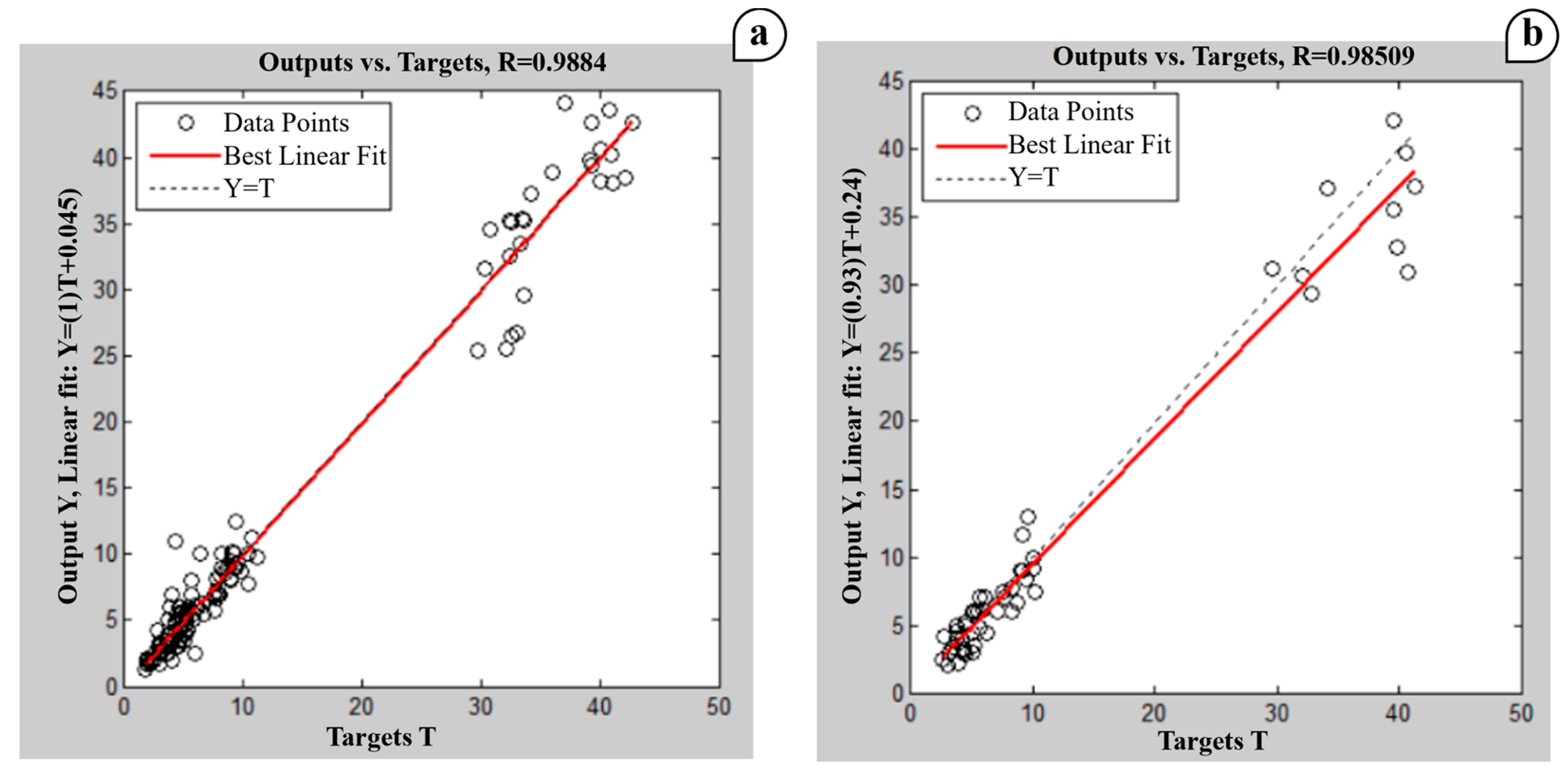
3.2. Artificial Neural Network (ANN)

ANN models are potent statistical tools that have been increasingly employed to model complex welding process systems in the last decade [34,35]. Typically, the ANN model performs better than regression analysis [36]. This study tried to develop a systematic, robust approach for interpreting the ANN model to investigate the butt fusion welding process of HDPE pipes. Unlike traditional regression, an ANN can capture subtle interactions between variables for finding accurate joint geometries in HDPE pipes. Moreover, ANNs can model complex, non-linear relationships between welding parameters and find the best joint profile for both cap and width, leading to more accurate predictions of optimal conditions.
The ANN model, using the dataset in Table 2, was divided into 70% training and 30% testing groups and designed for four input parameters (welding pressure, water temperature, soaking time, and cooling time), one hidden layer of 15 neurons, and five targets. The targets included tensile strength and welding profiles, which included both the height and width of the cap and the height of the welding joint. Moreover, sequential-order incremental training with learning functions was used. The tansig function activated the input/hidden layers, while the purelin function used hidden/output layers. Figure 6 shows the regression behavior throughout the training and testing stages of the ANN model training process. The maximum and minimum R-sq for training and testing were 0.9884 and 0.9851, respectively.
For the ANN model results, Figure 7 illustrates the impact of varying pressure on the welding profile of the HDPE joint. It should be noted that a gradual increase in joint cap height (upper surface) can be achieved when the welding pressure is varied, until we reach 0.78 bar, where the joint cap height begins to decrease. On the other hand, the joint cap width behaves differently, as it increases significantly after reaching 0.78 bar. When the pressure exceeds a certain threshold, the material starts to over-compress. As the pressure increases, the molten material is squeezed and flows towards the sides and upward, reducing the joint cap height and increasing the cap width. The joint root height and width of the tube’s lower surface do not differ much from the behavior of the upper surface, except that the values of cap height are relatively higher than the root height. The Earth’s gravity, the method of fixing the pipes, and the location from which the samples are selected may impact this.
Figure 8 shows that the gradual increase in welding pressure was insufficient to cause a noticeable change in the tensile strength until reaching 0.7 bar, where a significant change in the joint’s behavior began and its strength increased. This behavior can be explained by the fact that the bulk of the molten material was spreading only on the upper and lower edges of the joint, but increasing the welding pressure further led to the molten material beginning to soften more and flow better on the interface surface of the joint, forming a suitable heat-affected zone (HAZ) [4]. In general, better contact with the HDPE surface promoted more thorough melting and intermingling of the polymer chains.
Figure 9 shows a smooth increasing trend in the joint tensile strength, as well as the profile height and width of the upper surface (cap) and lower surface (root), as the plate temperature increases. Increasing the temperature can enhance the flow of the molten HDPE pipe material in the welding area, enabling it to reach all overlapping parts [37]. Additionally, it can expand the dimensions of the welding profiles on the upper and lower surfaces of the pipe, thereby enhancing the tensile strength [38]. The increase in plate temperature leads to more molten and less viscous material, thereby increasing the weld bead size.
Figure 10 demonstrates that a heating temperature of 240 °C for a P of 0.6 bar, ST of 2 min, and CT of 10 min yields the maximum strength of weld joints. Higher heating temperatures ensure that the HDPE material at the weld interface melts thoroughly and uniformly. This thorough melting allows for better interdiffusion of polymer chains across the weld interface, leading to a stronger, more cohesive bond.

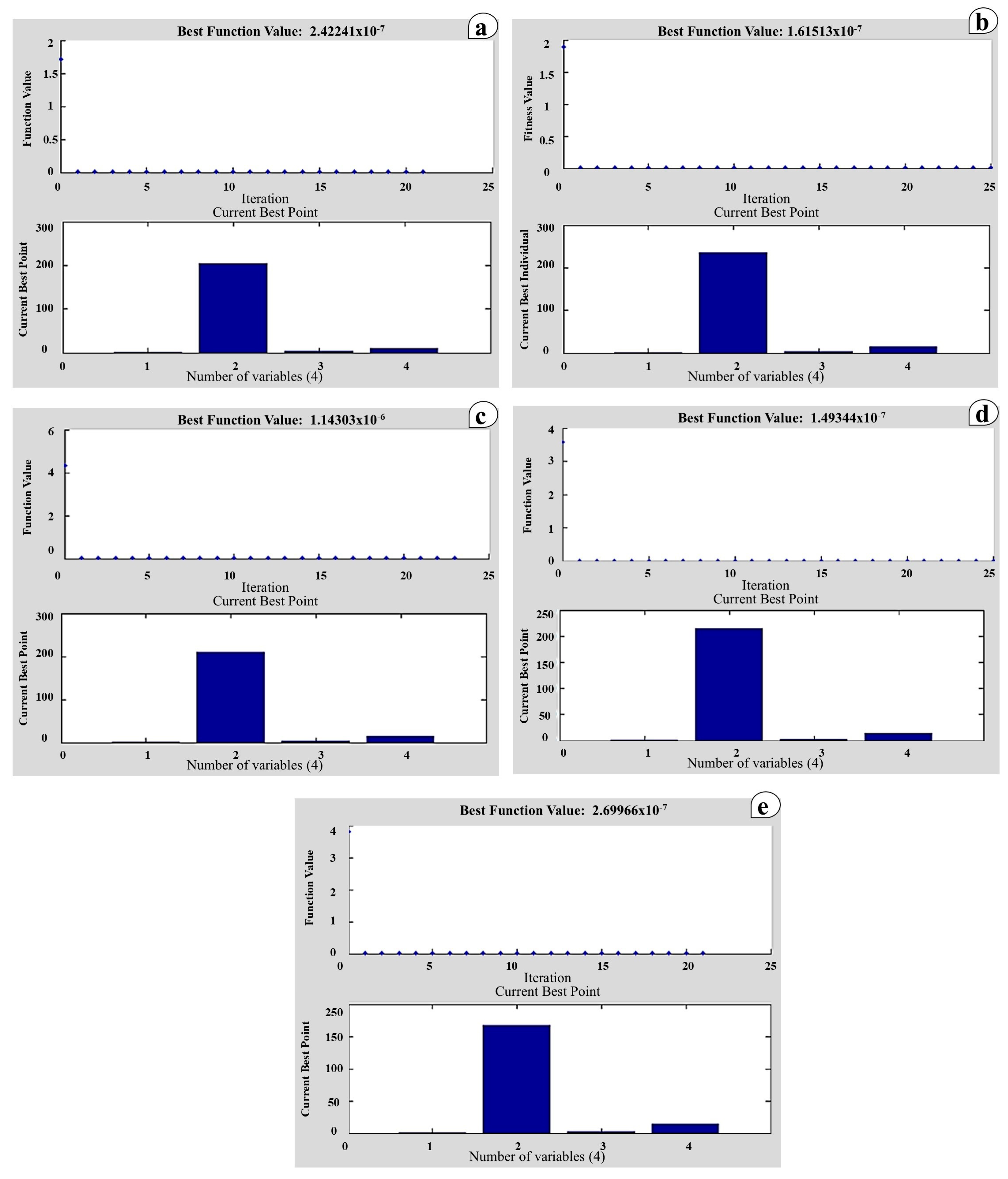
3.3. Genetic Algorithm Optimization

By mimicking the process of natural selection, the genetic algorithm (GA) is a computational method that finds optimal solutions to complex, constrained optimization problems [39]. The optimization of welding process parameters, including the minimum weld deposition rate and the maximum tensile strength and hardness, is a common application of the GA [40]. The MATLAB (R2010a) genetic algorithm toolbox was used to optimize the welding profile and tensile strength.
A single-point crossover was used, and each individual was constructed with a fitness function (obtained from the regression analysis model). An initial population of 50 and a crossover fraction of 0.8 were selected. The four input parameter range bounds were taken as follows: welding pressure 0.2–1 bar, plate temperature 160–240 °C, soaking time 2–6 min, and cooling time 10–15 min.
In optimization methods, especially genetic algorithms, the average of the output values is often taken as the objective threshold to minimize the objective function in dealing with HDPE processes [41]. So, the output goals of the butt-welding process parameters were considered as follows: cap height of 3.5 mm, cap width of 8 mm, root height of 4.5 mm, root width of 7 mm, and tensile strength of 35 MPa. Table 6 displays the optimal values of the process parameters, as well as the best possible welding profiles and tensile strength. Figure 11a–e show the fitness values and current best individuals for cap and root weld height, cap and root weld width, and tensile strength, respectively.

3.4. Pattern Search Optimization

Pattern search is an optimization method that does not require a gradient [42]. It is also known by other names, but this name has been spreading since Hooke and Jeeves launched it [43]. This method’s main principle is to search for values with the fewest errors. In many welding processes, including arc welding [44], friction stir welding [45], laser welding [46], etc., pattern search has become more and more popular in recent years. The objective function and welding parameter limits used in the pattern search analysis were the same as those used in the genetic algorithm. MATLAB R2010a was used, and the functions considered in the pattern search analysis are shown in Table 7. Figure 12 displays the fitness values, as well as the current best individuals for welding joint profiles and tensile strength.
It is known that the objective function value represents the measure of performance or error that the algorithm seeks to minimize (or maximize) in pattern search optimization. The mean value of the objective function provides a good impression of the algorithm’s stability and convergence evaluation. The optimal conditions of pressure, temperature, soak time, and cooling time (see Table 8) were selected to achieve the mean value of the objective function over multiple iterations. Table 8 displays the mean value of the objective function over the iterations for the following parameters: cap height (3.5 mm), cap width (8 mm), root height (4.5 mm), root width (7 mm), and tensile strength (35 MPa).
Comparing the genetic algorithm and pattern search algorithm can lead to investigating which approach is most suitable for optimizing the process parameters of butt fusion welding for the HDPE pipes. The comparison is based on the main equations of the joint profiles and tensile strength, as indicated in Table 3. The best results for both the genetic algorithm and pattern search approaches are indicated in Table 9. The results show the optimal response values corresponding to the optimal parameters obtained from the optimization technique. The values obtained from the pattern search algorithm are much closer to the desired values than those obtained from the genetic algorithm.

4. Conclusions

In this study, optimal butt fusion welding parameters that achieve ultimate tensile strength and welding profile geometries during HDPE pipe joining were explored. In addition to the heater plate temperature and welding pressure, both soaking and cooling times were investigated as welding process parameters. For welding profiles, the height and width of the joint cap were used to describe the profile of the upper surface joint of the HDPE pipe, while the height and width of the joint root were used to describe the profile of the lower surface joint of the HDPE pipe. Regression analysis based on ANOVA and an ANN was used to model the experimental sets. Then, genetic algorithm and pattern search approaches were used to optimize the butt fusion welding parameters and predict the corresponding tensile strength and welding profiles. The main points that can be concluded from this study are as follows:
  • The heater plate temperature is most significant for the welding joint profile, while the welding pressure is most significant for the joint’s tensile strength.
  • The results of the trained ANN model were more closely related to the experimental results than those of the regression analysis model based on ANOVA.
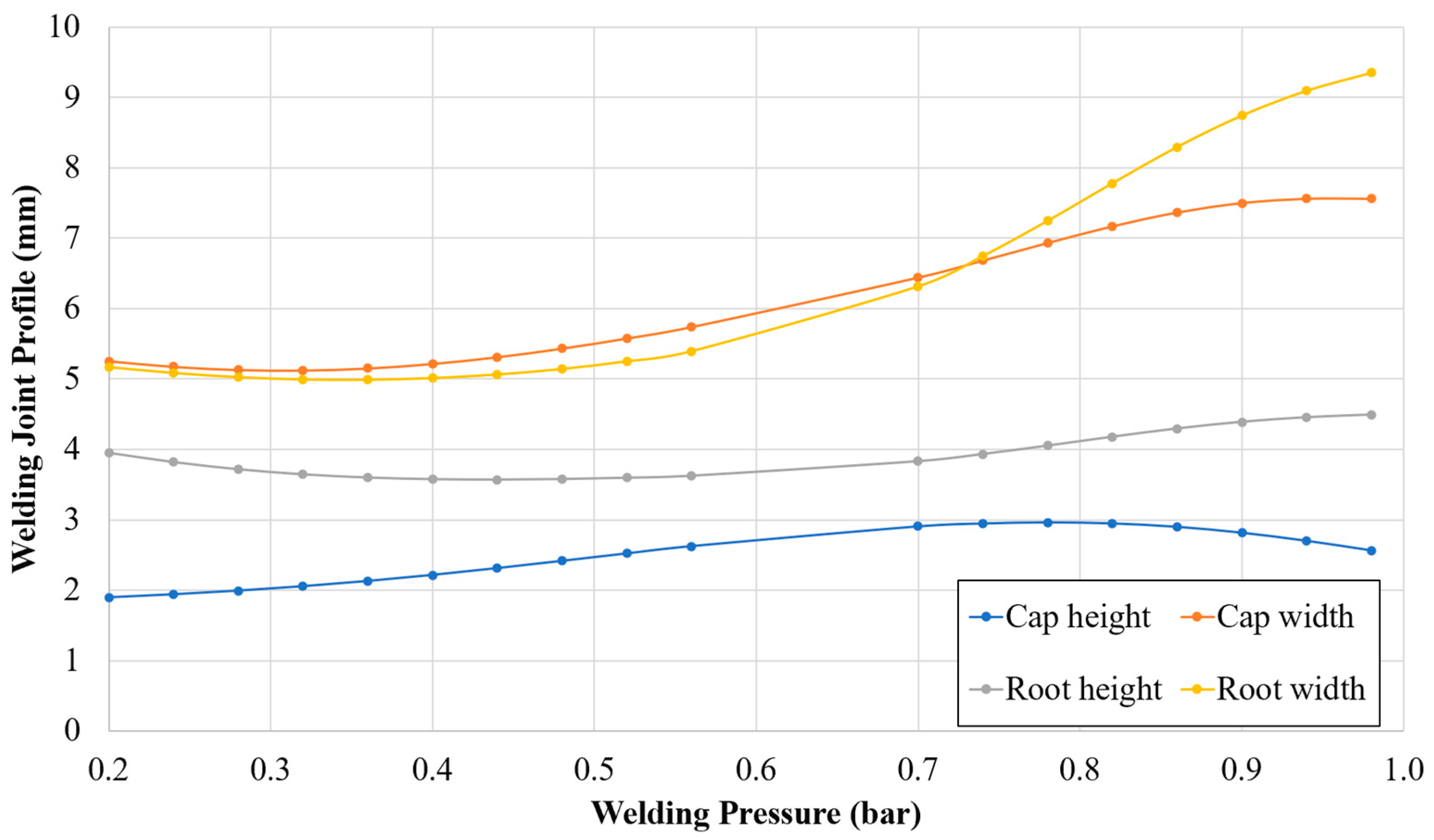
  • Within certain limits, the combined increase in heater plate temperature and welding pressure leads to a significant increase in tensile strength and weld profiles for both upper and lower surfaces.
  • For HDPE pipe joining, both pattern search and genetic algorithms can be considered suitable approaches for optimizing butt fusion welding parameters, with pattern search having a relative preference.

Author Contributions

Conceptualization, M.S.M. and R.J.J.; methodology, M.S.M. and R.J.J.; software, R.A.-S.; validation, R.A.-S., M.S.M. and R.J.J.; formal analysis, R.A.-S.; investigation, M.S.M. and R.J.J.; resources, R.J.J.; data curation, R.A.-S.; writing—original draft preparation, R.A.-S. and R.J.J.; writing—review and editing, M.S.M.; visualization, R.A.-S. and M.S.M.; supervision, R.J.J.; project administration, R.J.J. and M.S.M. All authors have read and agreed to the published version of the manuscript.

Funding

This research received no external funding.

Data Availability Statement

The data presented in this study are available on request.

Conflicts of Interest

The authors declare no conflicts of interest.

References

  1. Albertsson, A.C. Long-Term Properties of Polyolefins: Preface; Springer Science & Business Media: Berlin, Germany, 2004. [Google Scholar]
  2. Khajouei, M.; Khamani, S.; Adavi, K. Hybrid pipes for high performance and reliability. In Polymer Composite Systems in Pipeline Repair: Design, Manufacture, Application, and Environmental Impacts; Gulf Professional Publishing: Houston, TX, USA, 2023. [Google Scholar] [CrossRef]
  3. Ren, Y.; Sun, X.; Chen, L.; Li, Y.; Sun, M.; Duan, X.; Liang, W. Structures and impact strength variation of chemically crosslinked high-density polyethylene: Effect of crosslinking density. RSC Adv. 2021, 11, 6791–6797. [Google Scholar] [CrossRef] [PubMed]
  4. Tariq, F.; Naz, N.; Khan, M.A.; Baloch, R.A. Failure analysis of high density polyethylene butt weld joint. J. Fail. Anal. Prev. 2012, 12, 168–180. [Google Scholar] [CrossRef]
  5. Bai, C.; Lin, R.; Lai, H.S. Investigation of Creep Behavior of HDPE Pipe Butt Fusion Welded Joints Using a Stepped Isostress Method. Polymers 2024, 16, 1803. [Google Scholar] [CrossRef] [PubMed]
  6. Riahi, M.; Kooshayan, K.; Ghanati, M.F. Analysis of effect of pressure and heat on mechanical characteristics of butt fusion welding of polyethylene pipes. Polym.-Plast. Technol. Eng. 2011, 50, 907–915. [Google Scholar] [CrossRef]
  7. Lee, B.Y.; Kim, J.S.; Lee, S.Y.; Kim, Y.K. Butt-welding technology for double walled Polyethylene pipe. Mater. Des. 2012, 35, 626–632. [Google Scholar] [CrossRef]
  8. Tao, Y.; Guo, W.; Shi, Y.; Miao, C.; Tang, P. Study on Molten Zone of Butt Fusion Welding Process With Phased Array Ultrasonic Technology for Polyethylene Pipe. In Proceedings of the ASME 2023 Pressure Vessels & Piping Conference, Atlanta, GA, USA, 16–21 July 2023. V001T01A011. [Google Scholar] [CrossRef]
  9. Wang, Z.; Xu, L.; You, Q.; Peng, Y.; Zhang, Q. Design of an Intelligent Butt-Fusing Welding Machine for HDPE Pipes. In Proceedings of the ASME 2022 Pressure Vessels & Piping Conference, Volume 1: Codes and Standards, Las Vegas, NV, USA, 17–22 July 2022. V001T01A005. [Google Scholar] [CrossRef]
  10. Shapheek, M.; Shrivastava, N. Optimization of cooling time for polyethylene fusion joints. Mater. Today Proc. 2019, 28, 1267–1272. [Google Scholar] [CrossRef]
  11. Bucknall, C.B.; Drinkwater, I.C.; Smith, G.R. Hot plate welding of plastics: Factors affecting weld strength. Polym. Eng. Sci. 1980, 20, 432–440. [Google Scholar] [CrossRef]
  12. Pathak, S.; Pradhan, S.K. Experimentation and optimization of HDPE pipe electro fusion and butt fusion welding processes. Mater. Today Proc. 2019, 27, 2925–2929. [Google Scholar] [CrossRef]
  13. Shaheer, M. Effects of Welding Parameters on the Integrity and Structure of Hdpe Pipe Butt Fusion Welds. Ph.D. Thesis, Brunel University London, London, UK, 2017. [Google Scholar]
  14. Lai, H.S.; Tun, N.N.; Yoon, K.B.; Kil, S.H. Effects of defects on failure of butt fusion welded polyethylene pipe. Int. J. Press. Vessel. Pip. 2016, 139–140. [Google Scholar] [CrossRef]
  15. Faraz, A.; Zai, B.A.; Nisar, S.; Mansoor, A.; Ali, R. Measurement of structural performance of fusion weld with change of welding parameters in high-density polyethylene. J. Test. Eval. 2021, 49, 4364–4377. [Google Scholar] [CrossRef]
  16. Wang, Z.; Wang, B.; Xiang, A.; Jiao, D.; Yu, F.; Zhang, Q.; Zhao, X. Comparative study on the performance of butt fusion-welding processes for nuclear safety class large-diameter thick-walled PE pipes. Nucl. Eng. Technol. 2024, 139–140, 117–122. [Google Scholar] [CrossRef]
  17. Alkaki, S.S.; Kaman, M.O. Mechanical properties of electro and butt fusion welded high-density polyethylene pipes. Mater. Test. 2019, 61, 337–343. [Google Scholar] [CrossRef]
  18. Xingmin, Z.; Zhao, J.; Yan, J. Study on Constitutive Model for Butt Fusion Welded Joint of High density Polyethylene Pipe. China Plast. 2021, 35, 65–71. [Google Scholar] [CrossRef]
  19. Wan, Z.; Meng, D.; Zhao, Y.; Zhang, D.; Wang, Q.; Shan, J.; Song, J.; Wang, G.; Wu, A. Improvement on the tensile properties of 2219-T8 aluminum alloy TIG welding joint with weld geometry optimization. J. Manuf. Process. 2021, 67, 275–285. [Google Scholar] [CrossRef]
  20. Jassim, R.J.; Lieth, H.M.; Al-Sabur, R.; Alsahlani, A. Influence of welding parameters on optimization of the tensile strength and peak temperature in AISI 1020 alloy joints welded by SAW. In AIP Conference Proceedings; AIP Publishing: College Park, MD, USA, 2022; p. 020042. [Google Scholar] [CrossRef]
  21. Unt, A.; Salminen, A. Effect of welding parameters and the heat input on weld bead profile of laser welded T-joint in structural steel. J. Laser Appl. 2015, 27, S29002. [Google Scholar] [CrossRef]
  22. Riofrío, P.G.; Ferreira, J.A.; Capela, C.A. Imperfections and modelling of the weld bead profile of laser butt joints in hsla steel thin plate. Metals 2021, 11, 151. [Google Scholar] [CrossRef]
  23. Khalaf, H.I.; Al-Sabur, R.; Demiral, M.; Tomków, J.; Łabanowski, J.; Abdullah, M.E.; Aghajani Derazkola, H. The Effects of Pin Profile on HDPE Thermomechanical Phenomena during FSW. Polymers 2022, 14, 4632. [Google Scholar] [CrossRef]
  24. Zhao, H.; Shen, Z.; Booth, M.; Wen, J.; Fu, L.; Gerlich, A.P. Calculation of welding tool pin width for friction stir welding of thin overlapping sheets. Int. J. Adv. Manuf. Technol. 2018, 98, 1721–1731. [Google Scholar] [CrossRef]
  25. ASTM D 3035: 2008; Standard Specification for Polyethylene (PE) Plastic Pipe (DR-PR) Based on Controlled Outside Diameter. ASMT: West Conshohocken, PA, USA, 2008.
  26. ASTM D638; Standard Test Method for Tensile Properties of Plastics. Book of ASTM Standards. ASMT: West Conshohocken, PA, USA, 2022.
  27. Belaziz, A.; Mohamed, M. Experimental Study of the Weld Bead Zones of a High-Density Polyethylene Pipe (HDPE). J. Fail. Anal. Prev. 2018, 18, 667–676. [Google Scholar] [CrossRef]
  28. Djebli, A.; Aid, A.; Bendouba, M.; Talha, A.; Benseddiq, N.; Benguediab, M.; Zengah, S. Uniaxial Fatigue of HDPE-100 Pipe. Experimental Analysis. Eng. Technol. Appl. Sci. Res. 2014, 4, 600–604. [Google Scholar] [CrossRef]
  29. Velarde, G.; Binroth, C. Regression analysis: A good practice for parameter exploration and optimisation in laser welding process. Weld. Cut. 2011, 10, 322–328. [Google Scholar]
  30. Chikh, A.; Serier, M.; Al-Sabur, R.; Siddiquee, A.N.; Gangil, N. Thermal Modeling of Tool-Work Interface during Friction Stir Welding Process. Russ. J. Non-Ferr. Met. 2022, 63, 690–700. [Google Scholar] [CrossRef]
  31. Chicco, D.; Warrens, M.J.; Jurman, G. The coefficient of determination R-squared is more informative than SMAPE, MAE, MAPE, MSE and RMSE in regression analysis evaluation. PeerJ Comput. Sci. 2021, 7, e623. [Google Scholar] [CrossRef] [PubMed]
  32. Ahmad, M.A.; Sheikh, A.K.; Nazir, K. Design of experiment based statistical approaches to optimize submerged arc welding process parameters. ISA Trans. 2019, 94, 307–315. [Google Scholar] [CrossRef] [PubMed]
  33. Al-Sabur, R. Tensile strength prediction of aluminium alloys welded by FSW using response surface methodology—Comparative review. Mater. Today Proc. 2021, 45, 4504–4510. [Google Scholar] [CrossRef]
  34. Zhao, D.; Wang, Y.; Liang, D.; Ivanov, M. Performances of regression model and artificial neural network in monitoring welding quality based on power signal. J. Mater. Res. Technol. 2020, 9, 1231–1240. [Google Scholar] [CrossRef]
  35. Al-Sabur, R.; Slobodyan, M.; Chhalotre, S.; Verma, M. Contact resistance prediction of zirconium joints welded by small scale resistance spot welding using ANN and RSM models. Mater. Today Proc. 2021, 47, 5907–5911. [Google Scholar] [CrossRef]
  36. Kumar, R.; Aggarwal, R.K.; Sharma, J.D. Comparison of regression and artificial neural network models for estimation of global solar radiations. Renew. Sustain. Energy Rev. 2015, 52, 1294–1299. [Google Scholar] [CrossRef]
  37. Faraz, A.; Nisar, S.; Khan, M.A. Effect of welding parameters on the structural performance of fusion welded extruded and injection molded HDPE joints. J. Space Technol. 2014, 1, 114–119. [Google Scholar]
  38. Dai, H.; Peng, J. The effects of welded joint characteristics on its properties in HDPE thermal fusion welding. Mod. Phys. Lett. B 2017, 31, 1750185. [Google Scholar] [CrossRef]
  39. Brown, E.C.; Sumichrast, R.T. Evaluating performance advantages of grouping genetic algorithms. Eng. Appl. Artif. Intell. 2005, 18, 1–12. [Google Scholar] [CrossRef]
  40. Ahire, P.G.; Patil, U.S.; Kadam, M.S. Genetic Algorithm Based Optimization of the Process Parameters for Manual Metal Arc Welding of Dissimilar Metal Joint. Procedia Manuf. 2018, 20, 106–112. [Google Scholar] [CrossRef]
  41. Kang, J.; Chen, X.; Shao, Z. Optimization of High-Density Polyethylene Process Based on Molecular Weight Distribution and Chemical Composition Distribution under Uncertainty. In Computer Aided Chemical Engineering; Elsevier: Amsterdam, The Netherlands, 2015; Volume 37, pp. 881–886. [Google Scholar] [CrossRef]
  42. Alzantot, M.; Zhang, H.; Sharma, Y.; Hsieh, C.J.; Chakraborty, S.; Srivastava, M.B. GenatTack: Practical black-box attacks with gradient-free optimization. In Proceedings of the GECCO 2019—Proceedings of the 2019 Genetic and Evolutionary Computation Conference, Prague, Czech Republic, 13–17 July 2019. [Google Scholar] [CrossRef]
  43. Wang, S.; Da, X.; Li, M.; Han, T. Adaptive backtracking search optimization algorithm with pattern search for numerical optimization. J. Syst. Eng. Electron. 2016, 27, 395–406. [Google Scholar] [CrossRef]
  44. Prakash, C.; Singh, S.; Singh, M.; Gupta, M.K.; Mia, M.; Dhanda, A. Multi-objective parametric appraisal of pulsed current gas tungsten arc welding process by using hybrid optimization algorithms. Int. J. Adv. Manuf. Technol. 2019, 101, 1107–1123. [Google Scholar] [CrossRef]
  45. Simoncini, M.; Costa, A.; Fichera, S.; Forcellese, A. Experimental analysis and optimization to maximize ultimate tensile strength and ultimate elongation of friction stir welded aa6082 aluminum alloy. Metals 2021, 11, 69. [Google Scholar] [CrossRef]
  46. Guo, Z.; Jiang, H.; He, L.; Lei, Z.; Bai, R. CNN-empowered identification of heat source parameters from the cross-section profile of laser-welded zone. Int. J. Adv. Manuf. Technol. 2024, 130, 5441–5455. [Google Scholar] [CrossRef]
Figure 1. Phases developing during butt fusion welding according to pressure with time variation.
Jmmp 08 00187 g001
Figure 2. Sequential stages in the butt fusion welding process.
Jmmp 08 00187 g002
Figure 3. Joint profile for HDPE in the butt fusion welding process.
Jmmp 08 00187 g003
Figure 4. Main parts of the butt fusion welding machine.
Jmmp 08 00187 g004
Figure 5. HDPE specimens tensile test: (a) universal tensile machine, (b) specimen preparation according to ASTM D638, (c) specimen fixation, and (d) specimen during failure.
Jmmp 08 00187 g005
Figure 6. Regression analysis plotting of welding parameters used to train the algorithm: (a) training; (b) testing.
Jmmp 08 00187 g006
Figure 7. Influence of welding pressure on joint welding profile at T = 160 °C, ST = 2 min, and CT = 10 min.
Jmmp 08 00187 g007
Figure 8. Influence of welding pressure on joint tensile strength at T = 160 °C, ST = 2 min, and CT = 10 min.
Jmmp 08 00187 g008
Figure 9. Influence of heating plate temperature on joint welding profile at P = 0.6 bar, ST = 2 min, and CT = 10 min.
Jmmp 08 00187 g009
Figure 10. Influence of heating plate temperature on joint tensile strength at P = 0.6 bar, ST = 2 min, and CT = 10 min.
Jmmp 08 00187 g010
Figure 11. Genetic algorithm fitness values and current best individuals from the genetic algorithm results for (a) cap height, (b) root height, (c) cap width, (d) root width, and (e) tensile strength.
Jmmp 08 00187 g011
Figure 12. Pattern search fitness values and current best individuals from the genetic algorithm results for (a) cap height, (b) root height, (c) cap width, (d) root width, and (e) tensile strength.
Jmmp 08 00187 g012
Table 1. Welding process parameter levels.
Input ParametersUnitCode Level Value
−101
Welding Pressure Bar0.20.61
Heater Temperature °C160200240
Soaking Time Minute2 6
Cooling Time Minute10 15
Table 2. Process parameters and corresponding welding profile and tensile strength.
RunP
(bar)
T
(°C)
ST
(min)
CT
(min)
CapRootTensile
Stress
(MPa)
Height
(mm)
Width
(mm)
Height
(mm)
Width
(mm)
10.21602102.04.32.53.035.13
20.21602151.35.33.14.032.48
30.21606101.85.63.35.026.75
40.21606152.26.04.05.231.23
50.22002102.15.73.55.229.54
60.22002156.010.04.011.034.59
70.22006103.07.04.47.029.46
80.22006152.08.44.95.735.21
90.22402102.66.03.25.030.58
100.22402152.55.44.05.626.43
110.22406103.28.26.79.825.42
120.22406154.011.66.07.535.65
130.61602101.74.03.03.535.42
140.61602151.74.01.73.435.18
150.61606102.06.07.02.544.18
160.61606152.67.02.57.031.56
170.62002104.26.15.07.037.23
180.62002153.05.03.44.433.45
190.62006103.29.24.86.032.87
200.62006154.610.04.88.738.17
210.62402102.58.14.37.239.37
220.62402153.06.73.07.742.22
230.62406104.311.36.210.238.93
240.62406154.29.06.09.443.61
2511602102.05.52.66.025.57
2611602152.04.43.43.530.77
2711606103.38.24.07.042.59
2811606152.78.03.07.742.59
2912002102.47.52.88.337.36
3012002154.09.06.010.039.75
3112006106.010.08.09.040.58
3212006154.59.06.010.031.03
3312402103.28.54.09.538.49
3412402154.08.04.09.038.03
3512406105.013.06.09.039.75
3612406155.510.06.012.540.25
Table 3. Regression analysis equations for the welding profiles and tensile strength.
TermsRegression Analysis Equation
Cap Height
(Ch)
C h = 18.59 2.58 x 1 + 0.206 x 2 0.276 x 3 0.015 x 4 + 0.85 x 1 2 0.0005 x 2 2 + 0.0104 x 1 x 2 + 0.503 x 1 x 3 0.102 x 1 x 4 + 0.002 x 2 x 3 + 0.001 x 2 x 4 0.0236 x 3 x 4
Cap Width
(Cw)
C w = 28.8 + 1.8 x 1 + 0.25 x 2 0.186 x 3 0.878 x 4 + 3.07 x 1 2 0.0005 x 2 2 + 0.0133 x 1 x 2 + 0.271 x 1 x 3 0.592 x 1 x 4 + 0.003 x 2 x 3 + 0.002 x 2 x 4 0.0089 x 3 x 4
Root Height
(Rh)
R h = 13.3 + 0.58 x 1 + 0.153 x 2 + 0.2696 x 3 0.098 x 4 + 0.51 x 1 2 0.0004 x 2 2 + 0.0002 x 1 x 2 + 0.065 x 1 x 3 + 0.06 x 1 x 4 + 0.003 x 2 x 3 + 0.001 x 2 x 4 0.0492 x 3 x 4
Root Width
(Rw)
R w = 28.1 + 8.31 x 1 + 0.296 x 2 0.37 x 3 + 0.275 x 4 + 5.6 x 1 2 0.0006 x 2 2 + 0.0199 x 1 x 2 + 0.130 x 1 x 3 0.004 x 1 x 4 + 0.0018 x 2 x 3 0.0011 x 2 x 4 + 0.0239 x 3 x 4
Tensile Strength
(TS)
T S = 53.4 + 20.9 x 1 0.238 x 2 + 0.73 x 3 1.07 x 4 22.2 x 1 2 + 0.00036 x 2 2 + 0.0879 x 1 x 2 + 1.66 x 1 x 3 0.858 x 1 x 4 0.0083 x 2 x 3 0.00812 x 2 x 4 + 0.025 x 3 x 4
x 1 : welding pressure, x 2 : heater temperature, x 3 : soaking time, x 4 : cooling time.
Table 4. ANOVA for joint cap height and width.
SourceDFJoint Cap HeightJoint Cap Width
F-Valuep-ValueF-Valuep-Value
Regression124.610.0013.580.004
P (bar)10.380.5430.010.916
T (°C)16.910.0152.250.147
ST (min)10.230.6340.130.721
CT (min)10.000.9690.040.844
P (bar) * P (bar)10.210.6530.040.835
T (°C) * T (°C)18.460.0082.880.103
P (bar) * T (°C)10.620.4390.000.991
P (bar) * ST (min)15.490.0280.050.818
P (bar) * CT (min)10.350.5580.070.789
T (°C) * ST (min)11.170.2911.680.207
T (°C) * CT (min)10.450.5110.370.550
ST (min) * CT (min)10.710.4081.820.190
Error23
Total35
Table 5. ANOVA for joint root’s height and width and tensile strength.
SourceDFJoint Root HeightJoint Root WidthTensile Strength
F-Valuep-ValueF-Valuep-ValueF-Valuep-Value
Regression128.300.0004.450.0012.050.068
P (bar)10.090.7670.970.3360.860.363
T (°C)14.900.0373.480.0750.320.579
ST (min)10.050.8300.100.7520.060.815
CT (min)12.570.1230.130.7240.270.608
P (bar) * P (bar)11.310.2632.210.1514.900.037
T (°C) * T (°C)13.660.0682.850.1050.130.725
P (bar) * T (°C)10.490.4900.560.4621.540.227
P (bar) * ST (min)10.770.3910.090.7672.050.165
P (bar) * CT (min)15.710.0250.000.9910.860.363
T (°C) * ST (min)11.430.2440.170.6880.510.483
T (°C) * CT (min)10.860.3640.110.7400.770.390
ST (min) * CT (min)10.050.8280.180.6780.030.869
Error23
Total35
Table 6. Optimal genetic algorithm values of welding process parameters of HDPE pipes.
OutputsMean
Values
P
(bar)
T
(°C)
ST
(min)
CT
(min)
Cap Height (mm)3.5 mm0.952012.111.5
Cap Width (mm)8 mm0.932023.414.5
Root Height (mm)4.5 mm0.872242.4814.1
Root Width (mm)7 mm0.542182.3314.2
Tensile Strength (MPa)35 MPa0.451792.614.5
Table 7. Functions considered for pattern search optimization.
ParametersFunction
Poll MethodGPS positive basis 2 N
Complete PollOff
Polling OrderConsecutive
Mesh Size1
Expansion Factor2
Contraction Factor0.5
Table 8. Optimal pattern search values of welding process parameters of HDPE pipes.
OutputsMean
Values
P
(bar)
T
(°C)
ST
(min)
CT
(min)
Cap Height (mm)3.5 mm0.9332042.2410.5
Cap Width (mm)8 mm0.651994.313.2
Root Height (mm)4.5 mm0.9112352.5814.23
Root Width (mm)7 mm0.4832152.913.5
Tensile Strength (MPa)35 MPa0.451672.7414.6
Table 9. Comparison between the genetic algorithm and pattern search approaches.
ParametersMethodMean
Values
P
(bar)
T
(°C)
ST
(min)
CT
(min)
Best
Value
Cap Height (mm)GA3.5 mm0.952012.111.53.4859 mm
PS0.9332042.2410.53.4978 mm
Cap Width (mm)GA8 mm0.932023.414.57.9831 mm
PS0.906210.73.0213.958.0026 mm
Root Height (mm)GA4.5 mm0.872242.4814.14.4954 mm
PS0.9112352.5814.234.4989 mm
Root Width (mm)GA7 mm0.542182.3314.26.9822 mm
PS0.4832152.913.56.9852 mm
Tensile Strength (MPa)GA35 MPa0.451792.614.535.2044 MPa
PS0.451672.7414.634.9975 MPa
Disclaimer/Publisher’s Note: The statements, opinions and data contained in all publications are solely those of the individual author(s) and contributor(s) and not of MDPI and/or the editor(s). MDPI and/or the editor(s) disclaim responsibility for any injury to people or property resulting from any ideas, methods, instructions or products referred to in the content.

