Abstract
As the metal additive manufacturing (AM) field evolves with an increasing demand for highly complex and customizable products, there is a critical need to close the gap in productivity between metal AM and traditional manufacturing (TM) processes such as continuous casting, machining, etc., designed for mass production. This paper presents the development of the scalable and expeditious additive manufacturing (SEAM) process, which hybridizes binder jet printing and stereolithography principles, and capitalizes on their advantages to improve productivity. The proposed SEAM process was applied to stainless steel 420 (SS420) and the processing conditions (green part printing, debinding, and sintering) were optimized. Finally, an SS420 turbine fabricated using these conditions successfully reached a relative density of 99.7%. The SEAM process is not only suitable for a high-volume production environment but is also capable of fabricating components with excellent accuracy and resolution. Once fully developed, the process is well-suited to bridge the productivity gap between metal AM and TM processes, making it an attractive candidate for further development and future commercialization as a feasible solution to high-volume production AM.
1. Introduction
For the past 40 years, metal additive manufacturing (AM) technology with the capability of fabricating highly complex metal components with virtually no geometrical limitations has enabled new opportunities in product design and performance while reducing lead time, improving material efficiency, and creating more sustainable products [1]. A significant attention and interest of AM lies with the manufacturing industry to identify the possible mechanical systems that can be fabricated with metal AM techniques with reduced production cost over traditional manufacturing (TM) [2]. Currently, the inherent difference in process principles between metal AM and TM leads to two distinct manufacturing principles: (1) metal AM is best suited for producing complex, customized parts in small quantities and (2) TM dominates high-volume production [3]. While metal AM processes are capable of providing individually designed products with a high level of detail, TM processes with their fast and efficient production with great precision, in combination with their long-established, quality-assured, and widely implemented manufacturing techniques, make the competition incredibly difficult for AM to be implemented in high-volume production [4].
As metal AM technology evolves with an increasing demand for highly complex and customizable products [5], there is a critical need to fill the gap in terms of production speed between metal AM and TM processes. This paper presents the development of the scalable and expeditious additive manufacturing (SEAM) process, which capitalizes on the advantages of binder jet printing and stereolithography technologies to produce a new metal AM processing route in a more efficient manner. The SEAM process is not only expected to be suitable for a high-volume production environment but also to be capable of fabricating functional components with competitive quality in dimensional accuracy, resolution, and surface roughness. Once fully developed, the process is well-suited to bridge the productivity gap between metal AM and TM processes, making it an attractive candidate for future development and commercialization as a solution for a high-volume production AM technology.
In the subsections below, we provide a brief overview of the working principles of the relevant AM technologies (binder jet printing and stereolithography) and how they were leveraged in the design and technical development of the SEAM process.
1.1. Binder Jet Printing
Binder jet printing (BJP) is a metal AM technique that forms three-dimensional (3D) green parts by stacking two-dimensional (2D) slices by selectively dispensing liquid binding agents on a thin layer of metal powder. The workflow of BJP is depicted in Figure 1. After printing, thermal treatments, including debinding and high-temperature sintering, are carried out on the green parts to achieve the final metal objects [6].
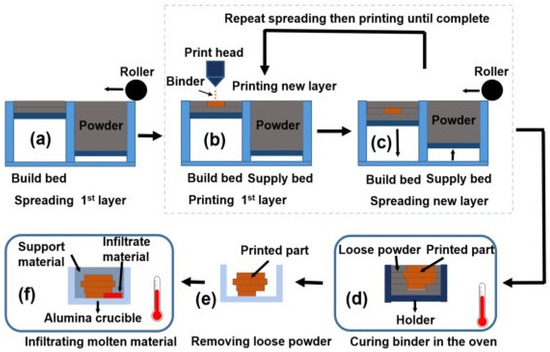
Figure 1.
Binder jet printing schematic diagram [6]. (a) Spreading 1st layer (b) Printing 1st layer (c) Spreading a new layer (d) Curing binder in the oven (e) Removing looase powder (f) Infiltrating molten material.
In comparison to other metal AM technologies, one of the most important advantages of BJP is the ability the fabricate components with isotropic microstructures. BJP is also able to fabricate green parts with virtually no limitation on the powder material [7]. Moreover, BJP can leverage the mature knowledge based on debinding and sintering of powder metallurgy (PM) and metal injection molding (MIM) technologies, directly applicable to BJP [8].
1.2. Stereolithography
Stereolithography (SLA) is an AM technology that involves the irradiation of ultraviolet (UV) light, typically by a laser or digital light projection (DLP) module, on the surface of a photosensitive liquid resin in a 2D pattern. Similar to most AM techniques, the patterns are extracted from a computer-aided design (CAD) model, or from scanned data from physical parts using imaging technologies such as magnetic resonance imaging (MRI) or computed tomography (CT). Upon UV irradiation, photoinitiator molecules in the resin are excited, forming free radicals and other reactive species, which initiates the cross-linking or photopolymerization of the resin [9]. As a result, the resin solidifies to a defined depth, causing it to adhere to the build substrate or the previous printed layer. The printing substrate then moves vertically by a layer thickness increment, and the process repeats until the solid 3D object is completed (Figure 2).
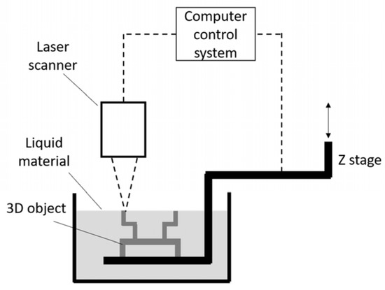
Figure 2.
Schematic diagram of stereolithography process [9].
SLA has been known as the fastest rapid prototyping technology available, due to the unique ability to generate 2D layer geometry in a single exposure using DLP projection [10]. Regarding accuracy and resolution, SLA is superior to all other AM techniques. Commercially available SLA machines are capable of generating extremely fine features with an accuracy of 20 µm, while the smallest details that other AM technologies can achieve typically fall between 50–200 µm in size [11]. Furthermore, the use of two-photon polymerization has recently enabled the ability to fabricate nano-sized features using SLA [12].
1.3. SEAM Process Overview
The SEAM process introduced in this paper capitalizes on the advantages of the aforementioned processes and the following three major steps as shown in Figure 3 are needed.
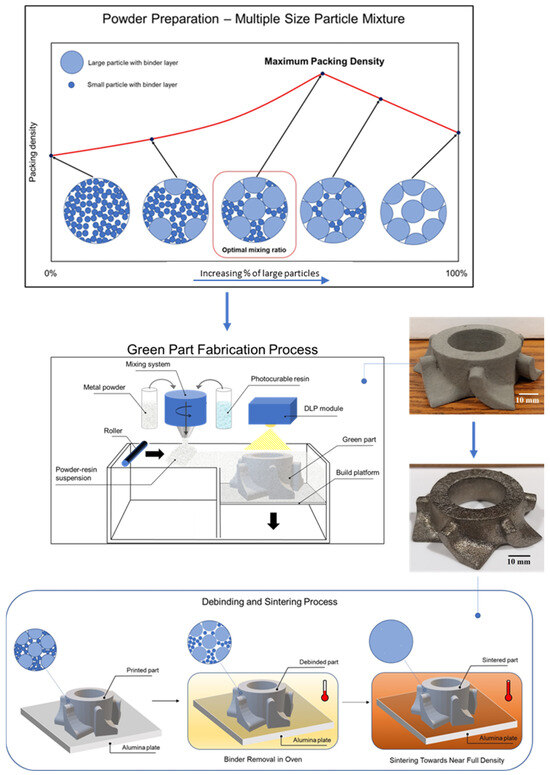
Figure 3.
SEAM process basic workflow.
- Step 1: A photosensitive suspension, which consists of metal powder and photopolymer resin, is formulated. The suspension properties must satisfy several criteria: high powder volume loading and appropriate viscosity to be processable in a layer-by-layer fashion using SLA techniques.
- Step 2: The suspension is shaped into three-dimensional (3D) green parts using the basic SLA technique. In a layer-by-layer fashion, ultraviolet (UV) light is selectively irradiated onto the suspension surface, which induces photopolymerization of the resin. The cured resin acts as a binder, holding the metal particles together, forming the desired 2D layer geometry. The irradiation patterns are extracted from the 3D CAD models, similar to other AM techniques.
- Step 3: The formed 3D geometry or green part is then subjected to appropriate thermal treatments for binder removal and high-temperature sintering in the same manner as the BJP process to achieve the final solid metal object.
Similarities can be drawn between the working principles of the SEAM process and currently available ceramic stereolithography systems, e.g., ADMATEC and Lithoz [13,14]. However, this paper will demonstrate that the SEAM process is designed specifically to show the potential to scale up to a higher production rate, while other ceramic SLA systems are typically employed on smaller build volumes for prototyping purposes [15,16]. Moreover, while some SLA system providers have claimed the capability of producing metal components, no academic literature has been published on this topic and no information regarding quality of the final part including density is available.
2. Development of the SEAM Printing System
2.1. Design Challenges and Considerations
One of the most critical challenges in the development of the SEAM process is the difficulty of maintaining the suspension’s stability during the printing process. The sedimentation velocity of a spherical metal particle in a liquid photopolymer can be derived from Stokes’ law [17] as:
where v is the sedimentation velocity, ρp is the density of the particle, ρf is the density of the fluid, g is the gravitational field strength, R is the radius of the spherical particle, and μ is the fluid viscosity, respectively.
Since the density of a typical metal powder material is many times higher than that of a photopolymer resin, the sedimentation behavior of the metal particles in the suspensions is inevitable. This undesirable behavior altering the composition of the metal suspension over time is detrimental to the printing process, which requires consistent and homogeneous suspension for every layer. Both the powder bed system and all the design iterations of SLA processes cannot accommodate this behavior, as they require the feedstock to be pre-filled either in the supply piston or material vat, and stay idle throughout the printing process. Figure 4 demonstrates the sedimentation behavior over time of a metal suspension consisting of 90 wt.% SS420 powder (Oerlikon Metco—Plymouth, MI, USA) and 10 wt.% CPS 3010 photopolymer (Colorado Photopolymer Solution—Boulder, CO, USA), which corresponds to a 56% volume percentage of powder. The densities of the metal powder and photopolymer resin are 8.05 g/cm3 and 1.12 g/cm3, respectively.
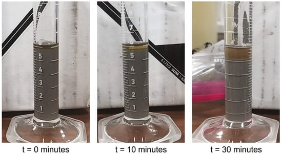
Figure 4.
Sedimentation behavior of SS420 suspension over time. In the graduated cylinder: grey region—SS420 powder; transparent green region—photopolymer resin. Reading unit is mL.
The second challenge in the processing of metal suspensions lies in the inherently weaker inter-layer bonding strength of suspensions in comparison to the pure resin used in traditional SLA processes [18]. The bottom-up SLA system design is especially susceptible to this behavior. As the part is gradually printed while being pulled upwards out of the material tank, the gravitational force exerted on every layer also gradually increases, which can eventually result in inter-layer cracking and part delamination [19]. The high density of metal powder further intensifies this effect, which can significantly limit the part fabrication capacity. Therefore, SEAM has adopted a top-down system design, as gravitational force does not oppose the inter-layer bonding.
The third challenge in the development of SEAM process hardware arises from the selection of a suitable curing system for metal suspensions. Since the mixture is densely filled with metal particles, the resulting light scattering causes difficulty in achieving an adequate cure depth for each layer and inter-layer bonding, which can be overcome by choosing a combination of high UV exposure intensity as well as extended exposure time [20]. A laser system must have a sufficient curing power density and a high enough resolution. However, the use of a laser is inferior to an image projection module in terms of processing speed on a production-scale system with a large build platform. Moreover, the nature of the point-by-point layer creation of laser scanning and the constant segregation of powder and resin in the print bed will result in non-uniformity even on each layer. This effect will be further intensified on a large print bed due to the extended time required to scan the geometry, as well as the inherent deterioration of beam quality in the outer area of the print bed [21]. The use of multiple lasers is a possible solution, but at the cost of a highly complex and expensive system design. As the development of the SEAM process is aimed towards a scalable system with high production speed and capacity, a dynamic mask curing system with its low cost and the ability to generate a complete 2D geometry quickly with a single exposure is more suitable.
In summary, the key design considerations for the development a SEAM printing system for the processing of metal suspensions are:
- The suspension must be kept homogeneous during the printing process. A mixing system capable of dispensing the suspension onto the printing platform layer by layer should be utilized;
- A top-down system design is preferred due to the weaker inter-layer bonding strength of the suspension layer. Moreover, the gravitational force acting on the printed part is against the printing direction in the bottom-up design, which can lead to layer delamination with a significant part size and weight;
- A dynamic mask curing system is desirable to ensure high printing speed as well as layer uniformity. However, the curing system must be carefully chosen to ensure adequate UV light intensity for initiating photopolymerization of the suspension.
2.2. Proof-of-Concept Experiments
2.2.1. Materials and Methods
A series of experiments were carried out to determine the feasibility of processing metal suspensions using three distinct patterning techniques: a physical mask, an LCD (liquid-crystal display) digital mask, and a DMD (digital micromirror device) digital mask. All experiments were carried out using the top-down projection setup. Specifications on the UV curing systems and experimental setup will be provided in the next sections.
Metal suspensions with a volume percentage of 56% metal powder loading were formulated and used for all experiments. The metal powder used was SS420, with a particle size of −55/+22 µm. CPS3010 (Colorado Polymer Solutions, Denver, CO, USA) was chosen as the photopolymer resin, due to its relatively low viscosity, commercial availability, as well as curing wavelength compatibility with existing lab equipment. The recommended curing wavelength of CPS3010 is 320–500 nm, and the available UV light source has a wavelength of 405 nm which is typical in 3D printing. Detailed information on CPS3010 is provided in Table 1.

Table 1.
CPS3010 photopolymer resin properties.
For each experiment, the metal suspension was first spread into a thin layer on a flat printing platform by a doctor blade, which was subsequently exposed to UV irradiation using the aforementioned patterning techniques to fabricate the part having a specific geometry for the irradiation time duration of 30, 60, and 90 s. The uncured materials were then removed and the photopolymerization behavior of the suspension was investigated for each experiment. In the cases where photopolymerization of the suspensions occurred and layer patterns were formed, additional thin layers of metal suspension were spread on top of the cured layer and again irradiated by UV light. This process was repeated up to a total of 10 layers having 150 µm thickness.
2.2.2. Physical Mask Experiment
This experiment evaluates the processability of metal suspensions by directly exposing a high-intensity UV light source.
- Experimental Setup
The physical mask used in this experiment was an aluminum sheet with dug-out holes of 5 cm in diameter, which allows light to pass through and form circular exposure patterns on the printing platform placed 1 cm below it. The thin layers of the formulated SS420 suspension were spread onto the printing platform manually using a doctor blade. A 25 W UV LED light (Shenzhen Chanzon Technology—Guangdong, China) was employed as the UV curing component, which directly irradiates 405 nm UV light through the physical mask onto the printing platform. Figure 5 shows the experimental setup.
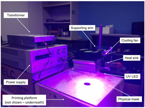
Figure 5.
Physical mask experimental setup, showing the UV irradiation from the LED light source through the dug-out hole on the mask.
- Result and Discussion
For all the experiments carried out with different layer irradiation times, photopolymerization was observed and circular patterns of 5.8 cm in diameter were formed. The difference in diameter between the dug-out hole on the physical mask and the pattern formed was due to the 1 cm gap between the mask and the printing platform. Additional layers were fabricated for each experiment up to a total of 10 layers. Figure 6 shows a sample fabricated with a layer irradiation time of 30 s.
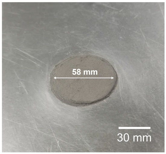
Figure 6.
Disk fabricated using physical mask setup. A total of 10 layers were fabricated with an irradiation time of 30 s for each layer.
2.2.3. Modified SLA System Experiment
This experiment evaluates the processability of metal suspension using a modified commercially available SLA system with an LCD digital mask.
- Experimental Setup
The Anycubic Photon S (Figure 7 (left)), a commercialized SLA LCD-based bottom-up 3D printer (Anycubic—Shenzen, China), was disassembled and reconstructed into a top-down projection setup (Figure 7 (right)). The original UV LED (5 W power, 405 nm wavelength) of the printer was replaced with higher-powered units of 25 W and 50 W (Shenzhen Chanzon Technology—Guangdong, China) for this experiment. The protective funnel was manufactured and used in the setup to prevent unwanted natural light exposure to the LCD screen and the printing platform underneath.
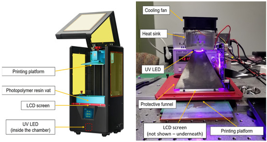
Figure 7.
Left: original LCD-based bottom-up Anycubic SLA 3D printer; right: modified SLA system setup, showing the top-down projection through an LCD mask; the original LED chip has been replaced with a higher power unit.
- Result and Discussion
For the experiments using the 25 W UV LED unit, no photopolymerization was observed for all irradiation times. A follow-up experiment was carried out with an extended irradiation time of 5 min, which resulted in a very weak photopolymerized layer. The 25 W LED unit was subsequently replaced with a 50 W unit. After 30 s of irradiation time, no photopolymerization was observed. Additionally, a dead zone on the LCD was observed, indicating that the 50 W LED had damaged the liquid crystal cells in the LCD screen.
In order to explain the results of the experiments, it is necessary to understand the working principles as well as the components of an LCD screen panel. Unpolarized light from a backlight unit travels through the first polarizing filter, which only allows vertically oriented light to pass through. Without the liquid crystal layer, the emitted light will be completely blocked by the second (crossed) polarizing filter. However, the arrangement of the molecules in the liquid crystal layer can be controlled electrically. In their natural state, the molecules position themselves in a helical or twisted structure, which rotates the incident light by 90°. The rotated light wave now aligned with the second polarizing filter can travel to the color filter to form a colored pixel. On the other hand, if a sufficient voltage is applied between the negative and positive electrodes, the liquid crystal molecules untwist, and the incident light’s orientation remains unchanged, and the emitted light is blocked by the second polarizing filter, which results in a dark pixel [22]. The LCD screens used in SLA processes in general and the Anycubic 3D printer in particular are monochromatic, i.e., they only generate black and white pixels since the color filter has been removed [23].
Liquid crystal molecules have been found to be extremely susceptible to damage from UV (<400 nm) and IR (>750 nm) light. Therefore, the polarizing films are usually selected so that their transmission wavelength range falls into the visible light region [24]. Typical film polarizers for visible light have an average transmission of 38%, with under 20% transmission in the near-UV region [25]. Monochromatic LCD screens used in SLA processes typically transmit only 6–10% of light at the 405 nm wavelength [26]. This extremely low transmissivity, in combination with the light scattering phenomena of metal suspensions, makes it extremely difficult to provide sufficient energy through an LCD screen to initiate photopolymerization. The 25 W LED unit could not overcome these issues, resulting in photopolymerization of the metal suspension only after an extended time of irradiation. The 50 W LED unit provided a higher light intensity, and therefore, a higher energy dosage. However, its usage even for a short time resulted in damage to the LCD screen. High-intensity light exposure has been found to be detrimental to the life and functionalities of the liquid crystal molecules [27].
In conclusion, LCD digital masking is not a suitable technique to process metal suspensions due to its limited near-UV light transmission. A different masking technique must be explored for the development of the SEAM process.
2.2.4. Modified DLP Projector Experiment
This experiment evaluates the processability of metal suspension using a modified DLP projector with a DMD digital mask.
- Experimental Setup
A commercialized DLP projector (S343, Optoma—New Taipei City, Taiwan) was positioned facing downwards towards the printing platform (Figure 8). The unit is equipped with a 203 W metal halide lamp as the light source. More detailed information on the projector can be found in Table 2. A holder frame was manufactured to place the projector at its minimum working distance of 25 cm. Two sets of experiments were carried out. First, the as-received DLP projector was used. Subsequently, the projector’s color wheel was replaced with an FSQ-KG5 heat-absorbing bandpass filter (Newport—Irvine, CA, USA), which prevented deep UV light transmission to the DMD chip. UV light with a wavelength under 325 nm has been found to be detrimental to DMD mirrors’ life and functionalities, as it is highly absorbable by DMD mirrors [28]. The transmissible wavelength range of the filter is shown in Figure 9.
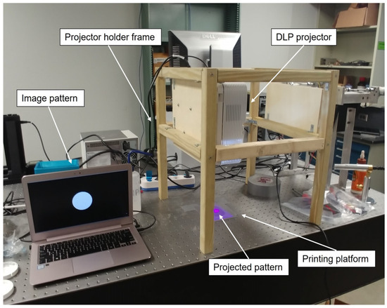
Figure 8.
Modified DLP projector experimental setup showing a circular pattern projected onto the printing platform. The color wheel has been replaced with the bandpass filter in this image.
Table 2.
Optoma S343 DLP projector specification.
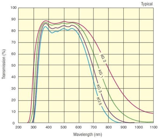
Figure 9.
Transmissible wavelength range of the FSQ-KG5 heat-absorbing bandpass filter (light blue line). Data are from [29].
- Results and Discussion
In the experiments carried out using the unmodified projector, no photopolymerization was observed independent of the irradiation time. After the color wheel was removed and replaced with the bandpass filter, photopolymerization of the metal suspension was observed after 90 s of irradiation time. Circular disk- and tensile bar-shaped samples were successfully fabricated with a total of 10 layers (Figure 10).
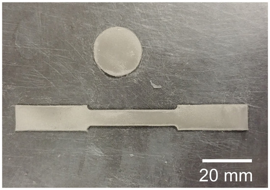
Figure 10.
Disk and tensile bar fabricated by the modified DLP projector. The color wheel in the projector has been replaced by a bandpass filter.
A follow-up experiment was carried out using the modified projector, to fabricate a 4 × 3 matrix of blocks with 1 × 1 cm cross section (Figure 11). A total of 20 layers were manually spread and cured with 90 s irradiation time per layer, resulting in parts of 1 mm in height. However, the two bottom right parts could not be fabricated as shown in Figure 11. DLP projectors utilize DMD chips to project and display patterns and images. A DMD chip consists of millions of highly reflective, individually controlled micromirrors. The mirrors can be tilted at an angle of ±12° and as often as 16,000 cycles per second to direct incident light towards (ON mode) or away from (OFF mode) the projector lens, which creates a greyscale projection image [30]. The shade or brightness of each pixel on the image depends on the frequency of the mirror in ON mode. The DMD chip is synchronized with a spinning color wheel, which splits the original light source into red (R), green (G), and blue (B), creating individual RGB colored images. As the human eye continuously averages the incident light on the retina every 1/50th of a second, full-spectrum color images can be achieved by controlling the display rate of individual RBG images [31].
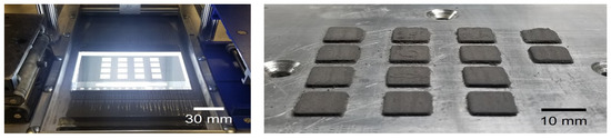
Figure 11.
Left: pattern projected by the modified DLP projector. Right: corresponding fabricated parts from the projected patterns. The bottom two parts failed to fabricate due to the low light uniformity of the projector.
In essence, the color wheel is a set of dichroic mirrors, which allows visible light to pass through and either absorbs or reflects away UV and IR light [32], resulting in a reduction in energy output from the original light source. Moreover, a portion of the output irradiation typically falls outside of the absorbing wavelength of the photopolymer resin (320–500 nm) [33]. Therefore, photopolymerization could not be obtained in the experiments with the unmodified projector.
Removal of the color wheel allows the full spectrum of the original light source to pass through, which has been a known technique since the early development of SLA technologies [34]. Typical metal halide lamps used in DLP projectors output a wide range of radiation wavelength, from deep UV to the far IR region [35]. The addition of the heat-absorbing bandpass filter in this experiment was aimed at reducing possible heating and optical damage to the DMD mirrors, while still allowing the projector to produce an effective radiation output in the 300–700 nm wavelength range, which encompasses the curing region of the photopolymer resin. After replacing the color wheel with the bandpass filter, sufficient energy was provided for photopolymerization of the suspension, resulting in successful fabrication of the samples. The failed fabrication of the bottom two samples was due to the low uniformity of the projector at 80% as shown in Table 2, i.e., the outer area of the projection plane receives 80% of the irradiation intensity in comparison to the center area.
The proof-of-concept experiments carried out using different lighting techniques have demonstrate the feasibility of processing metal suspensions using DMD digital mask technology. Multiple samples have been successfully fabricated in a layer-by-layer fashion using a DLP projector with modified optics. The selection of the curing system has proven to be critical in the metal suspension processing. Sufficient radiation power for photopolymerization, with a wavelength compatible with the photopolymer resin, and high projection uniformity are the important criteria that should be taken into consideration for a suitable curing system in the development of the SEAM process.
2.3. First-Generation Prototype of SEAM
The previous experiments have demonstrated the feasibility of processing metal suspensions using DMD digital masking and a top-down projection setup. Additionally, a mixing module must also be employed to maintain the metal suspension’s homogeneity throughout the printing process. Based on these findings, the printing system of the SEAM process was designed with the schematic working principles shown in Figure 12. The system adopts the powder bed design with a print bed, which is lowered by one layer thickness until the part is completely printed. The conventional supply bed is replaced by a top-down deposition system, which also serves as a mixing module. The system functions as follows: (a) the mixing module deposits a sufficient amount of the suspension for one layer while constantly mixing the suspension homogeneously, (b) a roller pushes the suspension from the deposition area to the print bed, (c) the DLP module projects the desired pattern on each layer of the print bed, (d) the print bed moves down by a layer thickness, and (e) the process repeats until the 3D part is completed. A first-generation fully functional SEAM system was designed and constructed (Figure 13).
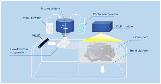
Figure 12.
Schematic diagram of the green part fabrication working principles of the SEAM process.
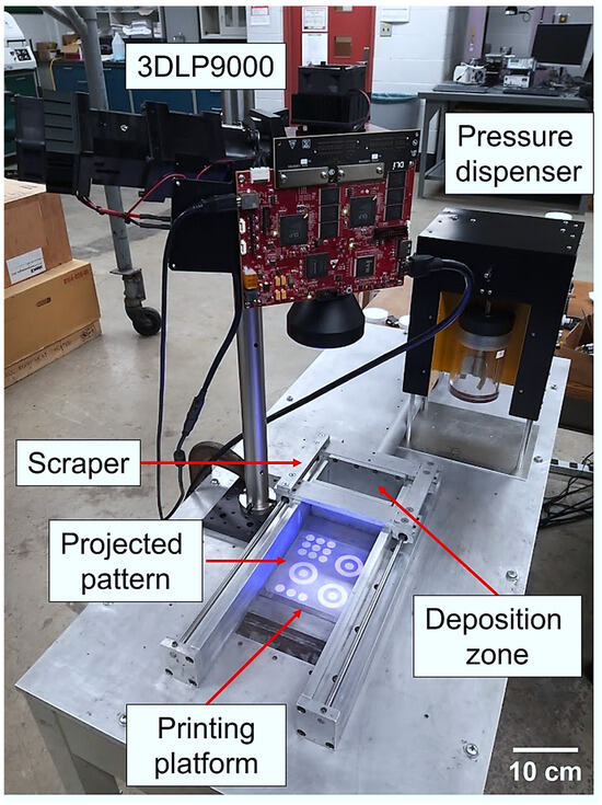
Figure 13.
First-generation SEAM system prototype showing its main components.
A printing platform with dimensions of 125 × 125 mm is connected to an ETH032 high-force screw drive electric cylinder (Parker Hannifin—Cleveland, OH, USA), which allows for a minimum moving distance of 50 µm. The mixing and dispensing module for the system is the 5-RPD-D1B Pressure Slurry Dispenser (Crist Instrument—Hagerstown, MD, USA), which includes a stirrer to provide a constant mixing of the media and deliver a consistent amount of suspension at a controlled pressure. Based on our findings from the previous section, the 3DLP9000 (Digital Light Innovations—Austin, TX, USA) is selected for the UV curing module. The 3DLP9000 is specifically designed for 3D-printing purposes, providing high uniformity and low distortion to help maximize the power delivered to the resin. The unit utilizes an LED as the light source with a wavelength of 405 nm, which is appropriate for many other commercially available resins on the market including the selected resin. The resolution of the unit is 100 µm pixel size with a maximum projection size of 192 mm × 320 mm. The scraper is connected to an HDA12-2 linear actuator (Servocity—Winfield, KS, USA) with a maximum moving speed of 50.8 mm/s. The double-bladed scraper design was employed to ensure layer flatness of both forward and backwards movements. NanoDLP, an open-source SLA slicer and controller software, was used to control and display the layer image pattern.
3. Green Part Fabrication
3.1. Suspension Formulation
One way to improve green density and consequently the density of the sintered part is to increase the packing density of the initial powder feedstock using bimodal or multi-modal powder sizes [36]. In a mixture of multi-modal powder sizes, the smaller powders fill interstitially among the larger particles and hence increase the overall packing density. The benefits of having a better-packed powder are to improve not only the final sintered density but also surface quality while minimizing the final shrinkage. Studies have shown that the green density of the printed part was improved by mixing two or more powder sizes and the optimal mixing ratios of multiple powder mixtures can be predicted using a linear packing model [37]. The predicted green packing density, γ, of powder constituents where each constituent is i is calculated by:
where ai,j and bi,j are the loosening and wall effect parameters, respectively, and can be calculated by:
In-house Python code was developed to utilize the equations above which take the tapped powder densities of two or more powder sizes as the inputs to calculate the optimal mixing ratio.
Given two or more powder sizes, a procedure to determine the optimal packing density can be carried out as follows:
- An amount of 100 g of each powder size is tapped for 20 min at 150 rpm up to five times in a graduated cylinder using a powder tapping device. The tapped packing density of the powder is taken as the average of all measurements;
- The calculated tapped density of each powder is used as input to the code to determine the optimal packing ratio;
- The different powder sizes combined based on the obtained packing ratio can be mixed using a high-speed mixer or a benchtop ball mill.
The powder-tapped density for the available powder sizes was experimentally determined, and the optimal size composition of their powder mixture was calculated. Consequently, an optimal powder mixture was produced, using a benchtop high-speed mixer (DAC 150.1 FVZ, FlackTek SpeedMixer—Greenville County, SC, USA) operating at 1500 rpm for 90 s. The powder mixture was subsequently combined with the photopolymer resin, CPS3010, to create the optimal suspension with a metal volume fraction of 0.56.
3.2. Printing Strategy
As discussed in the previous sections, due to the higher density of metallic powder in comparison to the photopolymer, the metal suspension is constantly segregating, with the metal powder settling out of the suspension (Figure 14a). While this issue can be solved initially by the constant mixing of the suspension in the dispenser, its effect is detrimental on the print bed. At the uncured area where the suspension is not solidified, a thin layer of pure photopolymer initially forms on top as the metal powder settles down. As the printing process continues, more powder particles from more layers of suspension settle to the bottom, which develop into a thicker layer of pure photopolymer. The thick liquid layer of photopolymer formed on top of the print bed cannot provide sufficient support for the next layer of suspension to be recoated (Figure 14b).
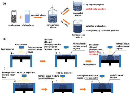
Figure 14.
Schematic diagram of (a) sedimentation of metal powder in the suspension, (b) printing challenges due to the gradual separation of metal and photopolymer resin in the print bed, and (c) the proposed two-step curing strategy.
In order to overcome the segregation of the suspension on the print bed, a two-step curing strategy was devised and employed for the SEAM process (Figure 14c). Before the layer geometry is projected by the DLP projector for a complete photopolymerization, the whole print area is exposed to UV light for a very short amount of time. The given low dosage of UV light partially photopolymerizes, or “soft-cures”, the suspension, converting it to a quasi-liquid state, which not only prevents the metal powder from settling out but also provides sufficient strength for the layer to support subsequently recoated layers, enabling the printing process to proceed. Finally, UV light is irradiated selectively for an extended time corresponding to the desired geometry to fully photopolymerize or “geometry cure”. After all the layers are fabricated, the soft-cured regions can be easily removed to retrieve the printed parts.
3.3. Processing Parameters
The relationship among particle sizes, critical energy dosage, and cure depth has previously been determined in our previous work [38]. The results indicated that an appropriate energy dosage to produce a cure depth of above 100 µm for the single-sized powder suspension is between 125 and 187.5 mJ/cm2, which corresponds to a curing time between 40 and 60 s. Experimentally, it has been determined that a curing time of 40 s was sufficient to produce good interlayer bonding. Therefore, the processing parameters used for the single-sized −53/+22 µm powder suspension were 40 s of geometry curing time and 100 µm layer thickness.
For the two-size powder mixture suspension, the presence of larger powder particles resulted in a lower energy dosage being required to produce sufficient curing depth. The processing parameters were determined to be 30 s of geometry curing time and 150 µm layer thickness. In order to determine the appropriate soft-curing time, single layers of metal suspension were spread on the printing platform at a controlled layer thickness. For each layer, the two-step curing strategy was carried out, with a soft-curing time of 1, 2, or 3 s, while holding the geometry cure time constant. The post-curing layer geometry was retrieved and inspected to determine the optimal curing time for metal suspensions of each metal. It was observed that a curing time of more than 3 s reduced the resolution of the layer geometry (Figure 15). On the other hand, good-quality layer geometry was produced with the soft-curing time of 1 or 2 s. The soft-curing time used to process the SS420 suspensions produced was determined to be 2 s.
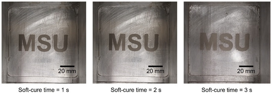
Figure 15.
Single layer geometry after different soft-curing times of 1, 2, and 3 s. Visible resolution loss is observed with 3 s of soft-curing time.
3.4. Fabricated Green Parts
Multiple sample sets which consist of cylindrical coupons, square blocks, and long bars were produced using the two-size powder mixture suspension. Figure 16 shows typical test coupons fabricated in a single build. A green turbine was finally fabricated to demonstrate the process’s capability of producing 3D structures (Figure 17). The turbine wings with overhang geometries were fabricated without any support structures with the soft-cured area providing sufficient strength to hold up the overhang structures. The two-step curing strategy has not only solved the suspension segregation issue in the print bed but also enabled the capability to fabricate overhang geometries without the need of additional support structures.
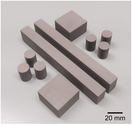
Figure 16.
SS420 green sample set fabricated from a single build using a two-size powder mixture suspension by the SEAM process.
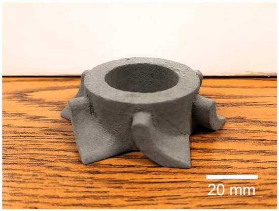
Figure 17.
SS420 green turbine fabricated by the SEAM process.
4. Sintering SEAM-Printed SS420 Parts to Full Density
4.1. Previous Related Work
The sintering of printed SS420 parts is a well-studied topic. Studies were first carried out to densify binder jet-printed parts by infiltrating molten bronze [39,40]. Parts were pre-sintered at different holding temperatures, and subsequently placed in contact with molten bronze at 1120 °C for infiltration. Pre-sintering at 1400 °C resulted in the lowest open porosity level of 5%. Activated sintering by the addition of sintering aids has also proven to be an effective method to achieve higher part relative density. Elements such as silicon (Si), nitrogen (N), and boron (B) have been known to lower the eutectic point of iron, which can be added to the initial powder feedstock to generate a consistent liquid phase during high-temperature sintering (Figure 18) [41].
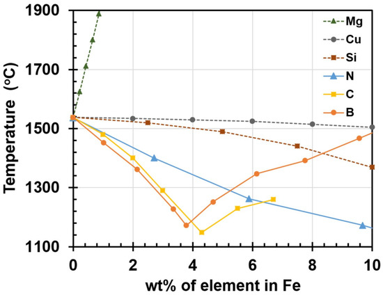
Figure 18.
Liquidus lines for various elements at different concentrations in iron [41].
The presence of liquid phase at the particle surface greatly enhances the densification process by enabling particle rearrangement and increasing mass transport rate through the liquid phase, which is typically multiple orders of magnitude higher than solid state diffusion [41,42,43,44]. SS420 parts printed by BJP, which also include 12.5 wt.% addition of Si3N4, can be sintered at 1225 °C to achieve a 95% dense part [45]. Do et al. [41] carried out an extensive study on the effect of boron additives (B, boron nitride (BN), boron carbide (BC)) and sintering temperature on the densification of BJP-printed parts. Notably, samples with above 99.5% relative density with no geometrical distortion were successfully fabricated by using a multi-size powder mixture feedstock with 0.5 wt.% BN addition, followed by vacuum sintering. The work carried out in this section extends Do et al.’s work to develop appropriate sintering conditions for SEAM-printed SS420 parts to achieve high density while maintaining part dimensional accuracy.
4.2. Experimental Setup
- From a compositional perspective, the SEAM and BJP parts should be identical after a complete removal of the binder except for two main differences:
- Initial powder packing density: the powder used in BJP is typically composed of multiple sizes with a high small/large particle radius ratio to achieve a higher packing density. By combining three different powder sizes with the average diameters of 82, 14, and 4 µm, a powder mixture with a packing density of 63.87% was produced for BJP. Several other studies also indicate the possibility of attaining a powder packing density of above 70% for BJP parts by including small powder particles of 5 µm and below [36,41]. On the other hand, the addition of the smallest powder particles significantly limits the curing depth of the suspension;
- Actual powder packing density in the feedstock: the powder feedstock used in BJP is the as-produced multi-sized powder mixture. As the material is spread on the printing platform, the particles are loosely packed but in contact with each other. In contrast, the feedstock used for the SEAM process is a mixture of metal powder and liquid photopolymer, typically at a 50–60 vol% of metal particles. Therefore, the interstitial spaces among the metal powder particles are filled with liquid photopolymer, resulting in an increase in inter-particle spacing. While the initial powder packing density is conserved as the green body densifies and shrinks during the sintering process, the initial inter-particle gap is inevitably higher in SEAM-printed parts in comparison to BJP-printed parts.
Therefore, the sintering conditions can be further optimized for SEAM SS420 parts in order to attain final parts with high relative density while ensuring shape retention. First, an analysis of variance was carried out on the published sintering data of SS420 [41] to gain further insight into the impact of sintering additive amount as well as sintering temperature on the final part density. The null hypothesis and alternate hypotheses are as follows:
Null hypothesis: Sintering additive and sintering temperature does not affect the final part density.
Alternate hypothesis: Sintering additive and sintering temperature have a statistically significant impact on the final part density at the alpha level.
Alpha level: 0.05.
Secondly, the previously determined optimal sintering conditions for BJP SS420 parts were applied to a debinded SEAM-printed coupon for a baseline relative density comparison. The optimal debinding cycle for fabricated green samples using CPS3010 has previously been determined [46] in an air environment: a ramp rate of 10 °C/min to 150 °C, a ramp rate of 1 °C/min to 430 °C, and a dwell time of 6 h followed by natural cooling to room temperature. All the samples fabricated in this study were debinded under the aforementioned heating cycle.
Subsequently, based on the measured density and previous analysis of variance results, an optimization matrix varying the wt.% of sintering additive and sintering temperature was designed to identify the optimal sintering conditions for SEAM-printed SS420 coupons. The matrix’s parameters are shown in Table 3. Each unit cell in the matrix corresponds to a different combination of the wt.% of BN (Sigma-Aldrich—St. Louis, MO, USA) and sintering temperature.
Table 3.
Optimization matrix for the sintering of SS420 samples printed with the SEAM process.
4.3. Results and Discussion
The analysis of variance of the literature data concerning the sintering of BJP SS420 parts revealed that for all three cases with different sintering additives, both sintering temperature and amount of addition have significant impacts on the final part relative density at the 0.05 alpha level. The main effect plots demonstrate that an increase in sintering temperature and amount of sintering additives increases the final part relative density (Figure 19, Figure 20 and Figure 21). As seen on the pareto charts, the effect of the amount of sintering additive is also more significant than holding temperature, at least in the cases of BC and BN addition.
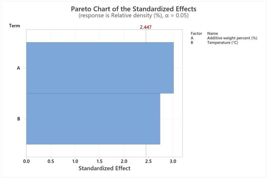
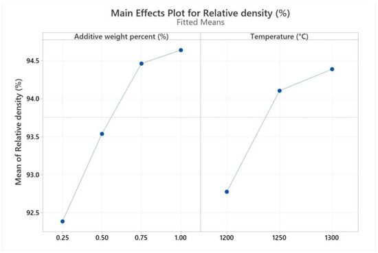
Figure 19.
Pareto charts and main effect plots of sintering temperature and additive wt.% addition on final part relative density for boron as sintering additive.
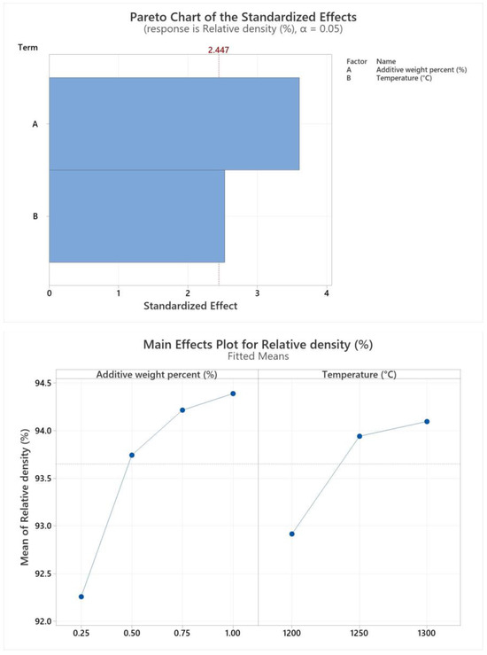
Figure 20.
Pareto charts and main effect plots of sintering temperature and additive wt.% addition on final part relative density for boron carbide as sintering additive.
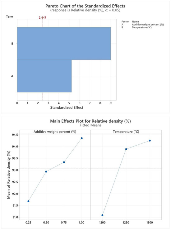
Figure 21.
Pareto charts and main effect plots of sintering temperature and additive wt.% addition on final part relative density for boron nitride as sintering additive.
The optimal processing conditions for SS420 fabricated by BJP have been determined to be a sintering temperature of 1250 °C with 0.5 wt.% of BN, resulting in a final relative density of 99.63%. The same processing conditions were applied to SEAM-printed samples, and the part density measured was 99.04%, which was averaged from three samples. The difference in final part density between SEAM- and BJP-printed parts can be attributed to the initial powder packing ratio. Due to the limitations on powder sizes, the experimental packing ratio of SEAM powder feedstock was 61.8%. However, the powder mixture combined with photopolymer resin reduced the packing ratio to 55.6 vol % due to the presence of interstitial spaces among the powder particles occupied by the resin. The initial green packing density has been linked to the final sintered density [36,41,45,47].
As both the sintering temperature and sintering additive have significant impacts on the final part density, the optimization matrix for SEAM-printed SS420 parts was designed with a sintering temperature between 1240 and 1260 °C and a weight of BN addition between 0.45 and 0.6 wt.%, which expanded on the optimal condition values from the literature. Figure 22 shows the SEAM sintered cylindrical coupons corresponding to the designed matrix. The measured relative densities of all the coupons are presented in Table 4.
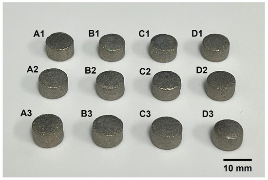
Figure 22.
SEAM-sintered SS420 coupons corresponding to the designed optimization matrix. Samples in column D exhibited “barreling” deformation.
Table 4.
SEAM-fabricated SS420 coupons relative density results.
From the results, samples C2, B3, and C3 all achieved a relative density of above 99.5%. Samples in column D of the optimization matrix also exhibited good relative density. However, the intended geometry was not maintained with those samples, indicating a combination of excessive liquid phase presence and/or unnecessarily high sintering temperature [48]. The obtained data also indicated that other possible combinations of sintering temperature and additive addition wt.% (higher additive addition with lower sintering temperature and vice versa) exist to achieve samples with good density and complete shape retention of the part. As these processing conditions directly affect the microstructure and mechanical properties of the fabricated components (grain size, hardness, chemical composition) [48,49,50], sintering conditions can be further tailored to suit the intended use and applications of the fabricated parts. A SS420 turbine which has a relative density of 99.7% was successfully sintered using the conditions developed in this section (Figure 23). EDS mappings showing the grain structure and chemical composition of a sample of the turbine are also included (Figure 24).
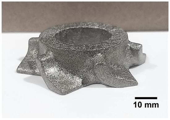
Figure 23.
SS420 turbine fabricated by the SEAM process.
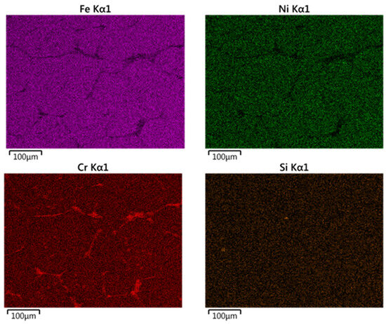
Figure 24.
EDS mappings of a sample from the sintered turbine.
5. Potential of the SEAM Process as a High-Volume Production AM Technology
One of the major advantages of the SEAM process over any other AM processes is its ability to generate large geometries efficiently. This can be achieved by layer projection using a DLP module to generate a whole-layer geometry by a single UV light exposure, which can be capitalized on to significantly increase the fabrication speed, surpassing any point-by-point layer creation methods. Fabrication time in BJP and other beam-based powder bed fusion (PBF) processes is directly related to layer geometry, i.e., large and complex geometry will take more time to be produced [21]. In contrast, DLP projection enables the printing time of each layer to be constant for every layer, regardless of layer geometry or size. For a large-scale fabrication system with complex layer geometry or multiple geometries, the use of DLP projection is even more advantageous. PBF systems are also difficult to employ on a large build area due to beam quality deterioration in the outer area of the print bed [51,52]. An additional laser or electron beam to increase build size results in an overly complex and expensive system [53,54].
The second advantage of the SEAM process in fabricating metal parts lies in the nature of the process which allows decoupling of the printing process and powder consolidation process. In the same manner as the BJP process, the SEAM-printed parts are consolidated isothermally, which results in residual stress-free parts with homogeneous microstructure and mechanical properties. In contrast, the quality of the final parts made from beam-based PBF processes is difficult to predict due to the complex microstructural evolution and variation throughout the fabrication cycle [54].
Lastly, once fully developed into a practical AM technology, the SEAM process offers a significant reduction in cost per part, unattainable with any other currently available AM technologies. The total manufacturing cost of AM processes in general can be categorized into three main areas: initial capital cost (printing system, sintering, and/or heat treatment furnaces), fabrication cost (labor, energy consumption), and post-processing cost (stress relief, surface finishing to practical standard).
- In terms of the initial capital cost, both PBF and SEAM processes require high-temperature furnaces to attain stress relief for PBF processes [55] or to enable sintering for SEAM. However, PBF printing systems themselves are well-known to be extremely costly due to their complexity in design as well as the use of an expensive laser or electron beam melting system which also requires accurate position control [21]. On the other hand, with its design simplicity and the utilization of an affordable DLP projection curing module, the SEAM printing system can be constructed for a fraction of the cost of PBF systems;
- For fabrication cost, PBF processes follow a linear cost model with respect to fabrication time as part quantity or volume increases, i.e., the more parts or the larger the part geometry, the longer the time required for fabrication, which translates to higher energy consumption and cost. The SEAM process offers a significant reduction in fabrication time, as its layer generation time is independent of the number of parts and layer geometry complexity or size. Moreover, the SEAM process offers a significant cost advantage in fabricating multiple parts simultaneously, due to the ability of debinding and sintering multiple parts in the same heating cycle, which can significantly reduce the energy consumption. Additionally, in situations where the target components require joining of multiple sub-components, the SEAM process also offers the unique ability to co-debind and co-sinter multiple green parts together in a single heating cycle to achieve the final joined and assembled components [46]. Producing the same assembled components using PBF processes requires not only the fabrication of sub-components, followed by necessary post-processing steps, but also a final mechanical joining and sealing, which further increases both the total time and cost of the manufacturing process;
- For post-processing operations, as-built parts fabricated by laser beam powder bed fusion (PBF-LB) require heat treatment for residual stress relief and several following surface finishing steps to attain a desirable surface quality [52]. On the other hand, due to the isothermal consolidation environment, as-built parts fabricated by the SEAM process are residual stress-free without additional heat treatment to relieve residual stress or microstructure homogenization. While a few studies have recommended a subsequent step of isostatic hot pressing after the sintering process to further eliminate residual pores, this research will demonstrate the feasibility of achieving fully dense parts with a single sintering cycle. With regard to surface finish, parts produced by furnace sintering and especially sintering in the presence of liquid phase are superior to laser-printed parts [56,57]. As the initial surface roughness plays a critical role in determining the required number of subsequent surface finishing steps of the parts [58,59,60], the SEAM process offers time and cost reductions in attaining the desired final surface quality.
If the SEAM process can be fully realized as a practical metal AM technique, it has the potential to provide a substantial reduction in production time and cost, while being capable of high-volume production. A comprehensive comparison on throughput between SEAM process and other prominent AM technologies has previously been presented [34]. Moreover, the advantages in part surface quality, along with uniform microstructure and freedom from residual stress, can put the SEAM process significantly ahead of other competing metal AM technologies.
6. Conclusions
This paper presents the development of the scalable and expeditious additive manufacturing (SEAM) process. After several proof-of-concepts, a fully functional prototype was designed and constructed. A series of experiments was subsequently carried out to optimize the processing conditions including printing, debinding, and sintering with SS420 and sintering additives, which successfully fabricated parts with above 99.7% relative density and no geometrical distortion. Despite major developmental efforts, the development of the SEAM process is still in its infancy. For further development towards an eventual industrial adoption, many fundamental challenges must be resolved: segregation of metal suspension, undesirable composition change during debinding, and precision and tolerance of the sintered parts. Once the SEAM process can be fully realized as a practical metal AM technique by solving these challenges, it has the potential to provide a substantial reduction in production time and cost, while being capable of high-volume production. Moreover, the advantages in part surface quality, along with uniform microstructure and freedom from residual stress, can put the SEAM process significantly ahead of other competing metal AM technologies.
Author Contributions
Conceptualization, H.X.N., P.K. and H.C.; methodology, H.X.N., P.K. and H.C.; investigation, H.X.N., B.P. and Z.Q.; data curation, H.X.N.; writing—original draft preparation, H.X.N.; writing—review and editing, P.K. and H.C.; supervision, P.K. and H.C.; project administration, H.C.; funding acquisition, H.C. All authors have read and agreed to the published version of the manuscript.
Funding
This research was funded by NSF CMMI 2236894.
Data Availability Statement
The data presented in this study are available on request from the corresponding author. The data are not publicly available due to privacy policy.
Conflicts of Interest
The authors declare no conflict of interest.
References
- Pereira, T.; Kennedy, V.; Patgieter, J. A comparison of traditional manufacturing vs additive manufacturing, the best method for the job. Procedia Manuf. 2019, 30, 11–18. [Google Scholar] [CrossRef]
- Beaman, J.J.; Bourell, D.L.; Seepersad, C.C.; Kovar, D. Additive Manufacturing review: Early Past to Current Practice. J. Manuf. Sci. Eng. 2020, 142, 110812. [Google Scholar] [CrossRef]
- Da Silveira, G.; Borenstein, D.; Fogliatto, F.S. Literature review and research directions. Int. J. Prod. Econ. 2001, 72, 1–13. [Google Scholar] [CrossRef]
- Tseng, M.M.; Jiao, J.; Merchant, M.E. Design for Mass Customization. CIRP Ann. 1996, 45, 153–156. [Google Scholar] [CrossRef]
- Gao, W.; Zhang, Y.; Ramanujan, D.; Ramani, K.; Chen, Y.; Williams, C.B.; Wang, C.C.L.; Shin, Y.C.; Zhang, S.; Zavattieri, P.D. The status, challenges, and future of additive manufacturing in engineering. Comput.-Aided Des. 2015, 69, 65–89. [Google Scholar] [CrossRef]
- Ziaee, M.; Crane, N.B. Binder jetting: A review of process, materials, and methods. Addit. Manuf. 2019, 28, 781–801. [Google Scholar] [CrossRef]
- Mostafaei, A.; Elliott, A.M.; Barnes, J.E.; Li, F.; Tan, W.; Cramer, C.L.; Nandwana, P.; Chmielus, M. Binder jet 3D printing—Process parameters, materials, properties, modeling, and challenges. Prog. Mater. Sci. 2021, 119, 100707. [Google Scholar] [CrossRef]
- Dini, F.; Ghaffari, S.A.; Jafar, J.; Hamidreza, R.; Marjan, S. A review of binder jet process parameters; powder, binder, printing and sintering condition. Met. Powder Rep. 2020, 75, 95–100. [Google Scholar] [CrossRef]
- Skoog, S.A.; Goering, P.L.; Narayan, R.J. Stereolithography in tissue engineering. J. Mater. Sci. Mater. Med. 2014, 25, 845–856. [Google Scholar] [CrossRef]
- Huang, J.; Qin, Q.; Wang, J. A Review of Stereolithography: Processes and Systems. Processes 2020, 8, 1138. [Google Scholar] [CrossRef]
- Melchels, F.P.W.; Feijen, J.; Grijpma, D.W. A review on stereolithography and its applications in biomedical engineering. Biomaterials 2021, 31, 6121–6130. [Google Scholar] [CrossRef] [PubMed]
- Park, S.-H.; Yang, D.-Y.; Lee, K.-S. Two-photon stereolithography for realizing ultraprecise three-dimensional nano/microdevices. Laser Photonics Rev. 2009, 3, 1–11. [Google Scholar] [CrossRef]
- Schwentenwein, M.; Schneider, P.; Homa, J. Lithography-Based Ceramic Manufacturing: A Novel Technique for Additive Manufacturing of High-Performance Ceramics. Adv. Sci. Technol. 2014, 88, 60–64. [Google Scholar]
- Cramer, C.L.; Wilt, J.K.; Campbell, Q.A.; Han, L.; Saito, T.; Nelson, A.T. Accuracy of Stereolithography Printed Alumina with Digital Light Processing. Open Ceram. 2021, 8, 100194. [Google Scholar] [CrossRef]
- ADMATEC—Admaflex 130 Evolution Ceramic and Metal 3D Printer for Additive Manufacturing of Sinterable Ceramics and Metals. Available online: https://admateceurope.com/admaflex130 (accessed on 22 August 2024).
- CeraFab S65|Industrial Ceramic 3D Printer. Lithoz: 3D Printing for Ceramics. Available online: https://lithoz.com/en/3d-printer/cerafab-s65/ (accessed on 22 August 2024).
- Cheng, P.Y.; Schachman, H.K. Studies on the validity of the Einstein viscosity law and Stokes’ law of sedimentation. J. Polym. Sci. 1955, 16, 19–30. [Google Scholar] [CrossRef]
- Bae, C.-J.; Ramachandran, A.; Chung, K.; Park, S. Ceramic Stereolithography: Additive Manufacturing for 3D Complex Ceramic Structures. J. Korean Ceram. Soc. 2017, 54, 470–477. [Google Scholar] [CrossRef]
- Zakeri, S.; Vippola, M.; Levänen, E. A comprehensive review of the photopolymerization of ceramic resins used in stereolithography. Addit. Manuf. 2020, 35, 101177. [Google Scholar] [CrossRef]
- Lee, J.W.; Lee, I.H.; Cho, D.-W. Development of micro-stereolithography technology using metal powder. Microelectron. Eng. 2006, 83, 1253–1256. [Google Scholar] [CrossRef]
- Chen, S.; Tao, F.; Jia, C.; Yang, J. Status and Progress of Selective Laser Melting Forming Technology. In Proceedings of the 2015 3rd International Conference on Machinery, Materials and Information Technology Applications, Qingdao, China, 28–29 November 2015; Atlantis Press: Amsterdam, The Netherlands, 2015; pp. 1295–1298, ISSN 2352-538X. [Google Scholar]
- Yang, D.-K.; Wu, S.-T. Fundamentals of Liquid Crystal Devices; John Wiley & Sons Inc.: Chichester, West Sussex, UK, 2014. [Google Scholar]
- Liqcreate. Monochrome vs. RGB LCD Screen in Resin 3D-Printing. Available online: https://www.liqcreate.com/supportarticles/monochrome-rgb-lcd-screen-resin/ (accessed on 28 January 2024).
- Liquid Crystal Displays. Available online: https://web.media.mit.edu/~stefan/liquid-crystals/node3.html (accessed on 26 August 2024).
- Muravsky, A.; Murauski, A.; Li, X.; Chigrinov, V.G.; Kwok, H.S. Optical Rewritable Liquid-Crystal-Alignment Technology. J. Soc. Inf. Disp. 2007, 15, 267–273. [Google Scholar] [CrossRef]
- Quan, H.; Zhang, T.; Xu, H.; Luo, S.; Nie, J.; Zhu, X. Photo-Curing 3D Printing Technique and Its Challenges. Bioact. Mater. 2020, 5, 110–115. [Google Scholar] [CrossRef]
- Kosc, T.Z.; Kozlov, A.A.; Papernov, S.; Kafka, K.R.P.; Marshall, K.L.; Demos, S.G. Investigation of parameters governing damage resistance of nematic liquid crystals for highpower or peak-intensity laser applications. Sci. Rep. 2019, 9, 16435. [Google Scholar] [CrossRef] [PubMed]
- Quijada, M.A.; Travinsky, A.; Vorobiev, D.; Ninkov, Z.; Raisanen, A.; Robberto, M.; Heap, S. Optical Evaluation of Digital Micromirror Devices (DMDs) with UV-Grade Fused Silica, Sapphire, and Magnesium Fluoride Windows and Long-Term Reflectance of Bare Devices. In Proceedings of the SPIE, the International Society for Optical Engineering/Proceedings of SPIE 2016, Edinburgh, UK, 26 June–1 July 2016. [Google Scholar] [CrossRef]
- FSQ-KG5 Heat Absorbing Glass Filter. Available online: https://www.newport.com/p/FSQ-KG5 (accessed on 28 January 2024).
- Ryoo, H.; Kang, D.W.; Hahn, J.W. Analysis of the effective reflectance of digital micromirror devices and process parameters for maskless photolithography. Microelectron. Eng. 2011, 88, 235–239. [Google Scholar] [CrossRef]
- Alvarez, J.; Richuso, J. Getting Started with TI DLP® Display Technology. Available online: https://www.ti.com/lit/an/dlpa059h/dlpa059h.pdf?ts=1720970366712&ref_url=https%253A%252F%252Fwww.google.com%252F (accessed on 14 July 2024).
- DrTune. English: Color Wheel from a DLP Projector. Wheel Has 6 Segments. Wikimedia Commons. Available online: https://commons.wikimedia.org/wiki/File:Dichroic_filter_from_a_DLP_projector_color_wheel.jpg (accessed on 18 April 2018).
- Sigma-Aldrich. UV Curable Resin Low Viscosity. Available online: https://www.sigmaaldrich.com/US/en/product/aldrich/900149 (accessed on 26 August 2024).
- Suryatal, B.K.; Sarawade, S.S.; Deshmukh, S.P. Fabrication of Medium Scale 3D Components Using a Stereolithography System for Rapid Prototyping. Journal of King Saud University. Eng. Sci. 2023, 35, 40–52. [Google Scholar] [CrossRef]
- Cohen, I.; Dubinsky, Z.; Erez, J. Light Enhanced Calcification in Hermatypic Corals: New Insights from Light Spectral Responses. Front. Mar. Sci. 2016, 2, 122. [Google Scholar] [CrossRef]
- Do, T.; Bauder, T.J.; Suen, H.; Rego, K.; Yeom, J.; Kwon, P. Additively Manufactured Full-Density Stainless Steel 316L with Binder Jet Printing. In Proceedings of the ASME 2018 13th International Manufacturing Science and Engineering Conference, College Station, TX, USA, 18–22 June 2018. [Google Scholar] [CrossRef]
- Du, W.; Ren, X.; Chen, Y.; Ma, C.; Radovic, M.; Pei, Z. Model Guided Mixing of Ceramic Powders with Graded Particle Sizes in Binder Jetting Additive Manufacturing. Volume 1: Additive Manufacturing; Bio and Sustainable Manufacturing. In Proceedings of the ASME 2018 13th International Manufacturing Science and Engineering Conference, College Station, TX, USA, 18–22 June 2018. [Google Scholar] [CrossRef]
- Nguyen, H.X.; Suen, H.; Poudel, B.; Kwon, P.; Chung, H. Development of an Innovative, High Speed, Large-Scaled, and Affordable Metal Additive Manufacturing Process. CIRP Ann. 2020, 69, 177–180. [Google Scholar] [CrossRef]
- Lu, S.L.; Meenashisundaram, G.K.; Wang, P.; Nai, S.M.L.; Wei, J. The combined influence of elevated pre-sintering and subsequent bronze infiltration on the microstructures and mechanical properties of 420 stainless steel additively manufactured via binder jet printing. Addit. Manuf. 2020, 34, 101266. [Google Scholar] [CrossRef]
- Cui, S.; Lu, S.; Tieu, K.; Meenashisundaram, G.K.; Wang, L.; Li, X.; Wei, J.; Li, W. Detailed assessments of tribological properties of binder jetting printed stainless steel and tungsten carbide infiltrated with bronze. Wear 2021, 477, 203788. [Google Scholar] [CrossRef]
- Do, T.; Kwon, P.; Shin, C.S. Process development toward full-density stainless steel parts with binder jetting printing. Int. J. Mach. Tools Manuf. 2017, 121, 50–60. [Google Scholar] [CrossRef]
- German, R.M.; Suri, P.; Park, S.J. Review: Liquid phase sintering. J. Mater. Sci. 2009, 44, 1–39. [Google Scholar] [CrossRef]
- German, R.M. Supersolidus Liquid Phase Sintering, Part II: Densification Theory. Int. J. Powder Metall. 2000, 26, 35–43. Available online: https://sid.ir/paper/593263/en (accessed on 26 August 2024).
- German, R.M. Supersolidus Liquid Phase Sintering, Part I: Process Review. Int. J. Powder Metall. 1990, 26, 23–33. Available online: https://sid.ir/paper/591874/en (accessed on 26 August 2024).
- Sun, L.; Kim, Y.-H.; Kim, D.D.-W.; Kwon, P. Densification and Properties of 420 Stainless Steel Produced by Three-Dimensional Printing with Addition of Si3N4 Powder. J. Manuf. Sci. Eng. 2009, 131, 061001. [Google Scholar] [CrossRef]
- Nguyen, H.X.; Suen, H.; Poudel, B.; Qu, Z.; Ahmad, M.U.; Kwon, P.; Bénard, A.; Chung, H. From Photopolymerization of Metal Suspension to Practical and Economical Additive Manufacturing of Haynes 214 Alloy for High Temperature Application. In Proceedings of the 2022 International Additive Manufacturing Conference, Lisbon, Portugal, 19–20 October 2022. [Google Scholar] [CrossRef]
- German, R. Sintering: From Empirical Observations to Scientific Principles; Butterworth-Heinemann: Oxford, UK, 2014. [Google Scholar]
- Liu, J.; Lal, A.; German, R.M. Densification and shape retention in supersolidus liquid phase sintering. Acta Mater. 1999, 47, 4615–4626. [Google Scholar] [CrossRef]
- Johnson, J.L.; Brezovsky, J.J.; German, R.M. Effect of liquid content on distortion and rearrangement densification of liquid-phase-sintered W-Cu. Metall. Mater. Trans. A 2005, 36, 1557–1565. [Google Scholar] [CrossRef]
- Johnson, J.L.; Upadhyaya, A.; German, R.M. Microstructural effects on distortion and solid-liquid segregation during liquid phase sintering under microgravity conditions. Metall. Mater. Trans. B 1998, 29, 857–866. [Google Scholar] [CrossRef]
- Yap, C.Y.; Chua, C.K.; Dong, Z.L.; Liu, Z.H.; Zhang, D.Q.; Loh, L.E.; Sing, S.L. Review of selective laser melting: Materials and applications. Appl. Phys. Rev. 2015, 2, 041101. [Google Scholar] [CrossRef]
- Li, S.; Yang, J.; Wang, Z. Multi-Laser Powder Bed Fusion of Ti-6.5Al-2Zr-Mo-V Alloy Powder: Defect Formation Mechanism and Microstructural Evolution. Powder Technol. 2021, 384, 100–111. [Google Scholar] [CrossRef]
- Poudel, B.; Nguyen, H.X.; O’Neil, A.; Ahmad, M.U.; Qu, Z.; Kwon, P.; Chung, H. Selective Laser Melting and Mechanical Properties of Oxide Dispersion Strengthened Haynes 214 Alloy. In Proceedings of the ASME 2022 17th International Manufacturing Science and Engineering Conference, West Lafayette, IN, USA, 27 June–1 July 2022. [Google Scholar] [CrossRef]
- Liu, S.; Zhu, H.; Peng, G.; Yin, J.; Zeng, X. Microstructure prediction of selective Laser melting AlSi10Mg using finite element analysis. Mater. Des. 2018, 142, 319–328. [Google Scholar] [CrossRef]
- Kruth, J.-P.; Deckers, J.; Yasa, E.; Wauthlé, R. Assessing and comparing influencing factors of residual stresses in selective laser melting using a novel analysis method. Proc. Inst. Mech. Eng. Part B J. Eng. Manuf. 2012, 226, 980–991. [Google Scholar] [CrossRef]
- Poudel, B.; Nguyen, H.X.; Kwon, P.; Chung, H. Selective laser melting of oxide dispersion strengthened MA956 alloy and its surface finishing by magnetic field assisted finishing. J. Manuf. Process. 2023, 97, 220–234. [Google Scholar] [CrossRef]
- Nguyen, H.X. Development of Scalable and Expeditious Additive Manufacturing Process: A Solution to High Production Additive Manufacturing—ProQuest. Available online: https://www.proquest.com/openview/74afed29c039bd77b58240da014095c3/1?pq-origsite=gscholar&cbl=18750&diss=y (accessed on 26 August 2024).
- Vasudevarao, B.; Natarajan, D.P.; Henderson, M.; Razdan, A. Sensitivity of RP Surface Finish to Process Parameter Variation 251. Available online: https://doi.org/10.26153/tsw/3045 (accessed on 26 August 2024).
- Poudel, B.; Nguyen, H.X.; Song, G.; Kwon, P.; Chung, H. Novel Process Modeling of Magnetic-Field Assisted Finishing (MAF) with Rheological Properties. Lubricants 2023, 11, 239. [Google Scholar] [CrossRef]
- Poudel, B.; Lee, P.H.; Song, G.; Nguyen, H.; Kim, K.; Jung, K.; Shao, C.; Kwon, P.; Chung, H. Innovative Magnetic-Field Assisted Finishing (MAF) using Nano-Scale solid lubricant: A case study on mold steel. Int. J. Precis. Eng. Manuf.-Green Technol. 2021, 9, 1411–1426. [Google Scholar] [CrossRef]
Disclaimer/Publisher’s Note: The statements, opinions and data contained in all publications are solely those of the individual author(s) and contributor(s) and not of MDPI and/or the editor(s). MDPI and/or the editor(s) disclaim responsibility for any injury to people or property resulting from any ideas, methods, instructions or products referred to in the content. |
© 2024 by the authors. Licensee MDPI, Basel, Switzerland. This article is an open access article distributed under the terms and conditions of the Creative Commons Attribution (CC BY) license (https://creativecommons.org/licenses/by/4.0/).