Article

Effect of Drilling Parameters on Surface Roughness and Delamination of Ramie–Bamboo-Reinforced Natural Hybrid Composites

1
Department of Mechanical & Industrial Engineering, Manipal Institute of Technology, Manipal Academy of Higher Education (MAHE), Manipal 576104, Karnataka, India
2
Department of MCA, NMAM Institute of Technology (NMAMIT), NITTE (Deemed to be University), Nitte, Karkala 574110, Karnataka, India
*
Authors to whom correspondence should be addressed.
J. Manuf. Mater. Process. 2024, 8(5), 195; https://doi.org/10.3390/jmmp8050195
Submission received: 28 July 2024 / Revised: 31 August 2024 / Accepted: 3 September 2024 / Published: 5 September 2024

Abstract

:
Plastics reinforced with glass fiber have a significant likelihood of being replaced by natural fiber hybrid composites (NFHCs). Making holes helps in part assembly, which is a crucial activity in the machining of composite constructions. As a result, choosing the right drill bit and cutting parameters is crucial to creating a precise and high-quality hole in composite materials. The present study employs the Taguchi approach to examine the delamination behavior and hole quality of ramie–bamboo composite laminates consisting of epoxy and nano-fillers (SiC, Al2O3) with feed, spindle speed, and three distinct drill bit types. Surface roughness and delamination are significantly influenced by feed and spindle speed, as indicated by the results of the analysis of variance. It was found that the spindle speed had a major impact on the delamination factor and surface roughness, while the feed and drill bit type had a minor influence. The surface roughness (76.5%) and delamination factor (66.7%) are significantly affected by the spindle speed.

1. Introduction

Natural fiber composites (NFCs) are materials made by combining at least one key element derived from a natural source. Structures reinforced with natural fibers have demonstrated significant potential to substitute synthetic fiber composites like carbon fiber-reinforced plastics (CFRP). They are cheap, biodegradable, lightweight, and less expensive compared to synthetic fibers. Replacing synthetic fibers with NFCs will reduce carbon emissions and help in controlling global warming. Natural fibers are derived from leaves, animals, seeds, minerals, etc. [1]. Among all these, ramie [2] and bamboo [3] fibers show exceptional physical properties that make them suitable replacements for synthetic materials. The performance of NFCs can be enhanced by adding nanofillers into the resin. Some such nanofillers are aluminum oxide (Al2O3), silicon carbide (SiC) [4], walnut powder [5], titanium dioxide (TiO2) [6], etc. Even after adding nanofillers, some factors like agglomeration might cause a reduction in the composite strength [7].
Drilling is a process of making precise holes in materials using tools that are rotating at high speeds. Holes are made to assemble components. The drilling of composites is a little different when compared to the drilling of metals as they are anisotropic and non-uniform. While machining composites, various factors such as delamination, surface roughness, and thrust force may affect the physical properties of the same [8,9]. Many researchers have been investigating different methods to reduce damage like fiber pullout and debonding caused by drilling and to maintain the structural integrity of NFCs. This damage can be observed using various imaging techniques, for instance, optical microscopes and x-ray-based imaging techniques [10]. While the drill bit is rotating at higher speeds, the area in contact may become uneven and lead to fiber pullout. This irregularity can be reduced by selecting the right factors like feed rate, spindle speed, drill type, drill diameter, etc. [11,12]. It was observed that with a larger diameter of the drill bit and at a higher feed rate, the delamination factor was minimal on various natural fiber composites made of epoxy resin [13]. Similar results were observed by Xu et al. [14] where feed rate became the dominant factor. It was concluded that a low feed rate resulted in reduced delamination. In another study [15], it was found that with a decrease in feed rate, there is a decrease in thrust force for all types of drill bits. This study was carried out on sisal-reinforced natural fiber composites with epoxy and polypropylene as matrices. The presence of irregularities like burrs is not only a sign of improper structural integrity but also increases machining cost as the irregularities need to be removed [16]. Molded holes showed better performance than drilled holes in the case of jute/epoxy composites. Variable results were observed using 4 mm and 8 mm drill bits [17]. This again proved that drill diameter is one of the critical factors.
It was found that the combination of low feed and high speed gave the best results for the parabolic drill bit, which minimized torque and thrust force [18]. During the drilling process, due to rough surface interactions and dissipation of friction energy in the form of heat, debonding within the composite may be caused. In particular, some NFCs may burn due to their low fire resistance. This causes degradation of physical properties and hence, wet drilling conditions are used [19]. After investigating the drilling behavior of hemp/glass hybrid composites, it was observed that plexi point and parabolic drills showed lower delamination size and low thrust force [20]. Recent studies on drilling glass–bamboo hybrid composites have revealed that utilizing a center drill with increased spindle speeds and reduced feed rates significantly minimizes delamination [21]. Similarly, studies on drilling ramie fiber woven composite showed that there is close correlation between thrust force value and delamination damage [22]. Experimental studies on natural fiber-based composites showed that there is a direct correlation between delamination factor and feed rate [23,24].
From the above literature, it can be concluded that drilling-induced damage in fiber-reinforced composites, such as delamination and burr formation, can be significantly reduced by optimizing machining parameters and tool geometry. Proper selection of these factors is crucial in minimizing defects and improving the quality of the drilled holes. By carefully adjusting these variables, CFRP components’ structural integrity and performance can be enhanced. Therefore, this study investigates the impact of cutting parameters such as feed rate, spindle speed, and the type of drill bit on the drilling performance of woven ramie–bamboo hybrid natural fiber composites. The primary output variables analyzed in this research are the delamination factor and surface roughness. The Taguchi technique is used to develop a design of experiments with different parameters.

2. Materials and Methods

Composites were manufactured using woven ramie, bamboo fibers as reinforcements, LY-556 epoxy as resin (Diglycidyl ether of bisphenol-A), and HY-991 as the polymer matrix. To check fiber strength, single-fiber tensile tests for both ramie and bamboo were conducted at Konkan Specialty Poly Products Pvt Ltd., in Mangalore, the results of which are included in Table 1, along with the other physical properties of the materials used in Table 1 and Table 2. Five composites were made with different fiber stacking sequences namely TS1, TS2, TS3, TS4, and TS5, the compositions of which are given in Table 3. Each composite specimen consisted of eight layers stacked using the hand layup technique with a thickness of 5 ± 0.5 mm and underwent compression molding for 24 h. The TS1 composite consists of only ramie fibers alternatively stacked in perpendicular directions while TS2 composite consists of only bamboo fibers stacked in a similar manner. TS3 composite consists of ramie and bamboo fibers alternatively stacked in perpendicular directions. TS4 and TS5 composites are composed of nano fillers, namely Al2O3 and SiC, respectively added to ramie and bamboo fibers alternatively stacked in perpendicular directions. Drilling was performed using a computer numerical control vertical machining center for all composites, with a maximum spindle speed of 6000 rpm. All the drilling experiments were carried out under dry conditions.
The specimen was fixed steadily with a plate on the top which is illustrated in Figure 1. For the drilling of ramie–bamboo-reinforced hybrid composites, three different types of drill bits were used, which are: twist drill, step drill, and core drill. All the drill bits are of a constant diameter of 8 mm and are shown in Figure 2. The machining parameters used for drilling are shown in Table 4. These parameters were used to develop a Taguchi design in Minitab V15 software. The L27 orthogonal array for delamination factor and surface roughness are shown in Table 5 and Table 6 respectively. The composite strips were cut into 250 × 25 mm using an abrasive water jet cutting machine. A total of 135 holes were drilled, with 27 holes on each composite. The measured output variables were the delamination and surface roughness. To calculate the delamination factor, Equation (1) was used [28].
Delamination   factor = D m a x / D n o m
where D m a x is the maximum diameter (mm), D n o m is the nominal hole diameter (mm).
The image of the drilled holes was captured and then imported into ImageJ V 1.8.0 software and output variables were measured by setting the right threshold frequency. Main effect plots and optimization plots were obtained using Minitab V15 software.
Nikon Stereo Zoom microscope (SMZ74T series) as shown in Figure 3 was used to obtain the magnified image of the damage caused by drilling. The surface roughness of the hole was measured using a Mitutoyo SJ-210 contact surface profilometer, featuring a 2.4 mm traversing length and a 0.8 mm cutoff value. The average roughness was determined from four measurements taken at different positions parallel to the hole’s axis. Figure 4 illustrates the surface roughness measuring instrument.

3. Results and Discussion

3.1. Surface Roughness Analysis

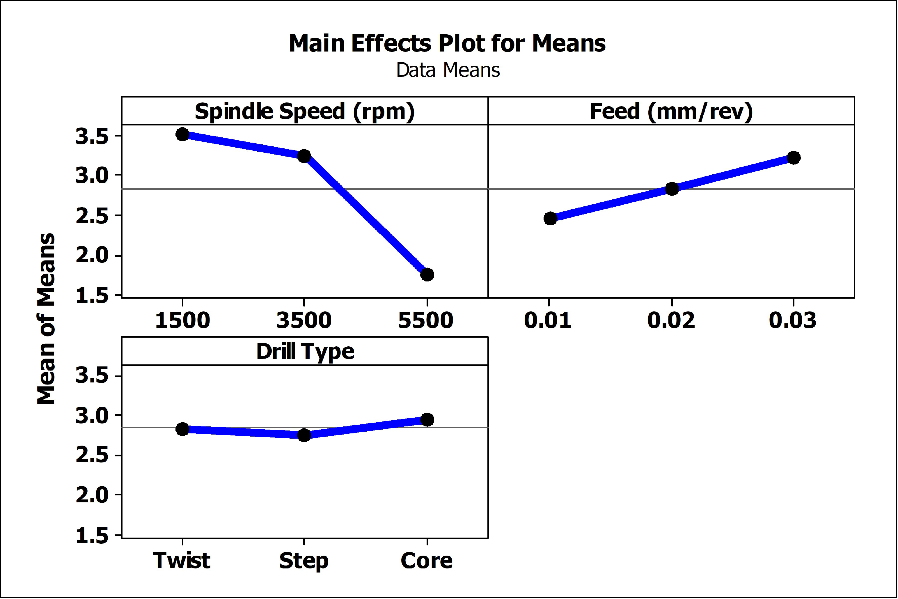
Surface roughness is an important factor in predicting the quality of the hole. It depends on several factors like cutting speed, feed rate, drill type, point angle, etc. The Main Effects Plot for Means (Figure 5 and Figure 6) sheds important light on the effects of spindle speed, feed rate, and drill type in the examination of surface roughness during drilling. A decrease in the mean surface roughness is observed as the spindle speed is increased from 1500 to 5500 rpm. This is due to built-up edge (BUE) which forms at low speeds and disappears [29], and roughness reduces, demonstrating the advantageous effect of higher speeds on producing smoother finishes. On the other hand, different feed rates show that lower values, especially at 0.01 mm/rev, significantly reduce surface roughness, highlighting the critical role that feed rate plays in maximizing surface quality [30]. Regarding drill bit performance, the step drill bit consistently shows the lowest mean roughness when compared to twist and core drill bits.
In the case of bamboo composite (TS2), lowest surface roughness was noted at a spindle speed of 5500 rpm and a feed rate of 0.01 mm/rev. On the other hand, for hybrid composite (TS3), maximum surface roughness was obtained at a spindle speed of 1500 rpm and a feed rate of 0.03 mm/rev. Though both maximum and minimum were seen in the case of a core drill bit, the step drill showed noticeable results in this drilling process.
In the current experiment, the goal was to reduce surface roughness and delamination factor; the “smaller is better” setting was used [31]. The S/N ratio is given by Equation (2).
S N = 10 l o g [ 1 n i = 1 n y i 2 ]
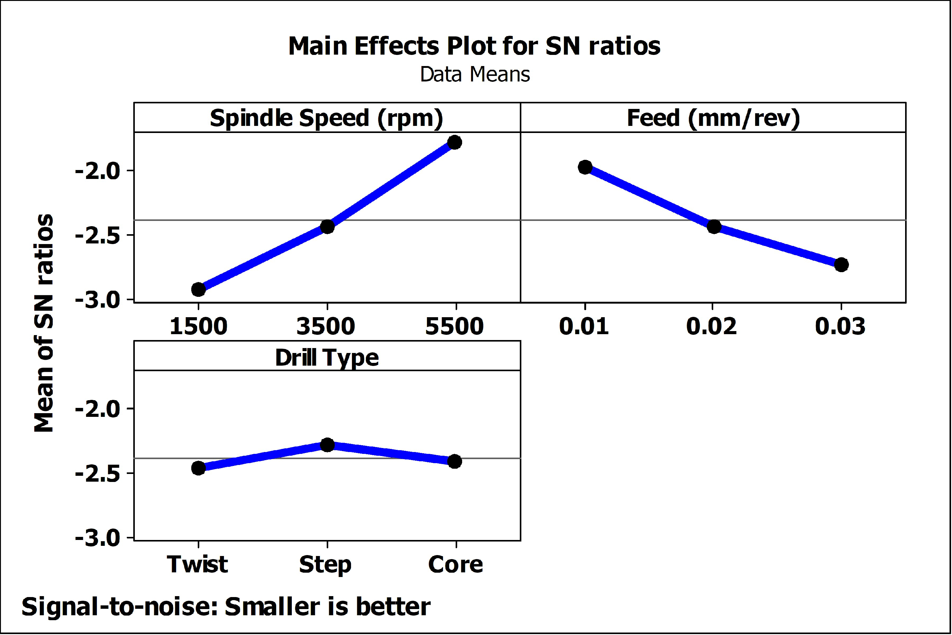
where, y = responses for the given factor level combination and n = number of responses. Generally, the greater the S/N ratio, the better it is. According to the main effects plot for S/N ratios, a higher spindle speed of 5500 rpm leads to better results in the surface finish. The lower feed rates of 0.01 mm/rev and core drills are the most important conditions for getting a smoother surface finish. This is because the S/N ratio, which normally exhibits lower values for rougher surfaces, clearly favors step drills over twist and core drills when the feed rate increases. A minor rise in the S/N ratio suggests that there may be less roughness at higher speeds (5500 rpm), but the effect seems less substantial.
From Table 7, one can observe that the spindle speed has more effect on the surface roughness in this experiment and is ranked 1, followed by feed and drill type. A step drill consists of two different diameters from the start to end; in this case, the primary drill is 4 mm and the secondary drill is 8 mm in diameter. The primary one has a low chisel edge and makes a pilot hole initially, and then the secondary drill enters the already drilled hole, reducing workpiece interaction and helping in heat dissipation. Hence, the damage is reduced, which has been proven in several studies [32,33].
S/N ratios are at three different levels for drill type, feed rate, and spindle speed. The difference between the maximum and minimum S/N ratios for each component is represented by the delta values, which are as follows: spindle speed has the highest delta value (6.399), suggesting a significant effect on the response, followed by feed rate (Delta = 2.885), while drill type has the least impact (Delta = 0.383). The ranking demonstrates that spindle speed is the most important factor followed by feed rate and drill type.
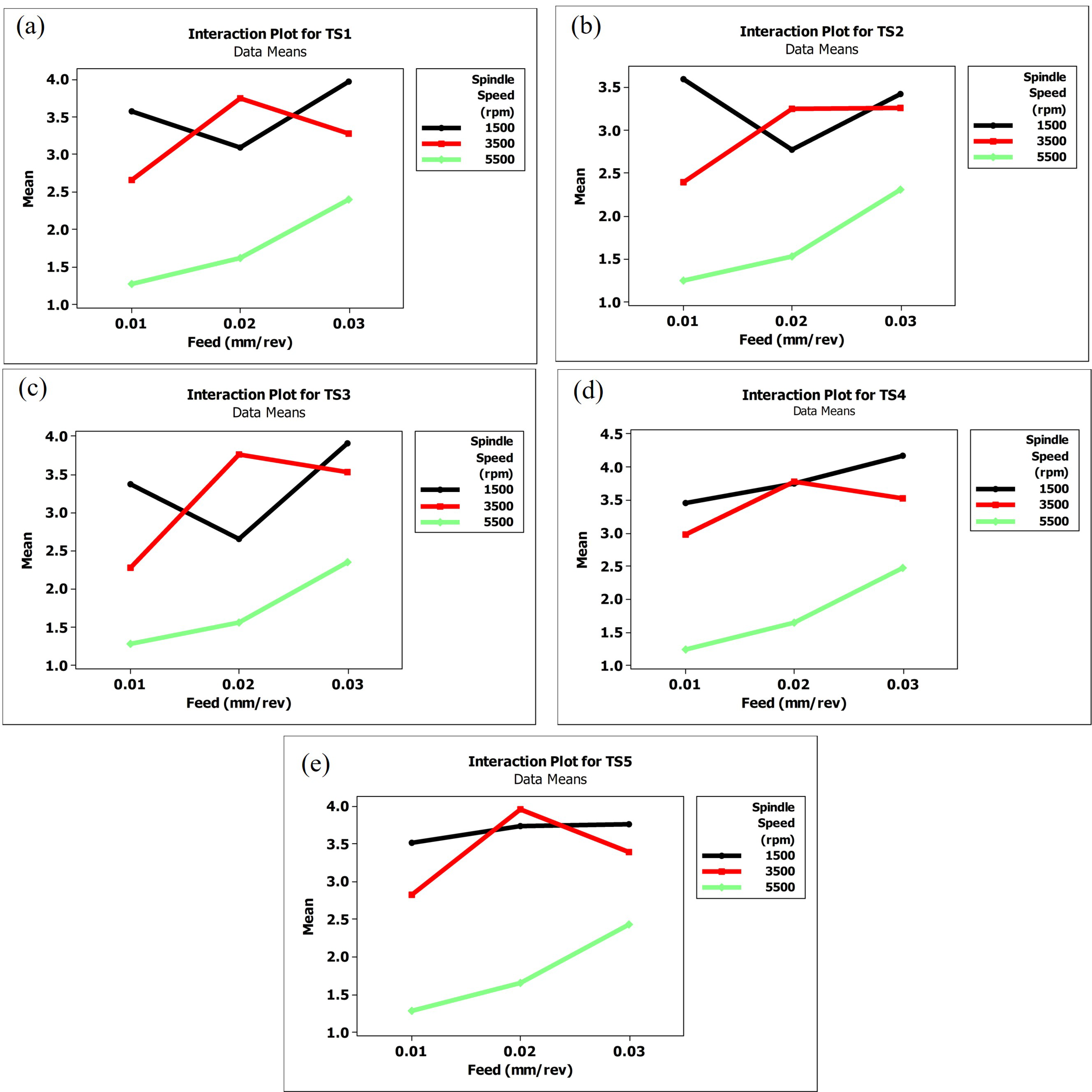
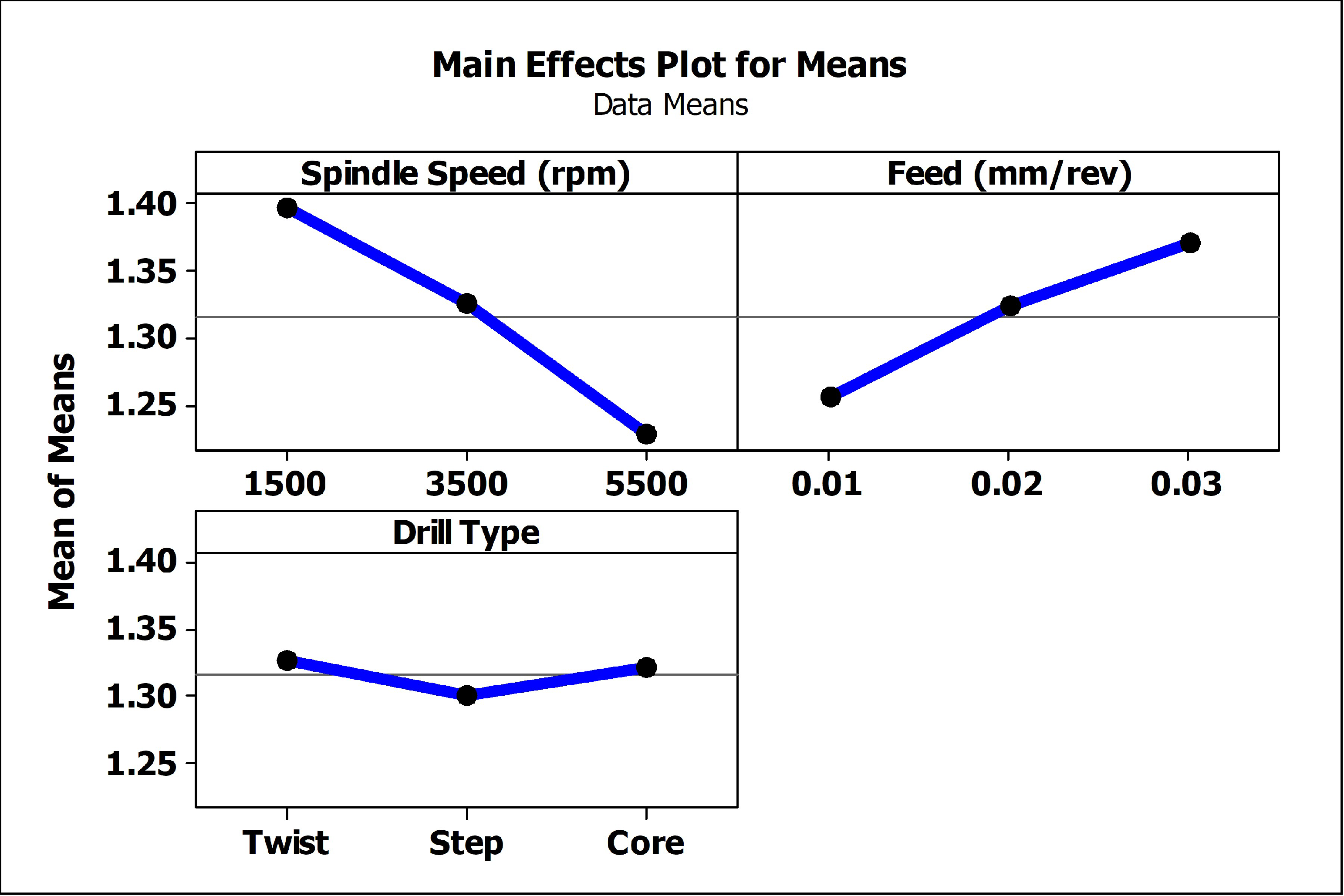
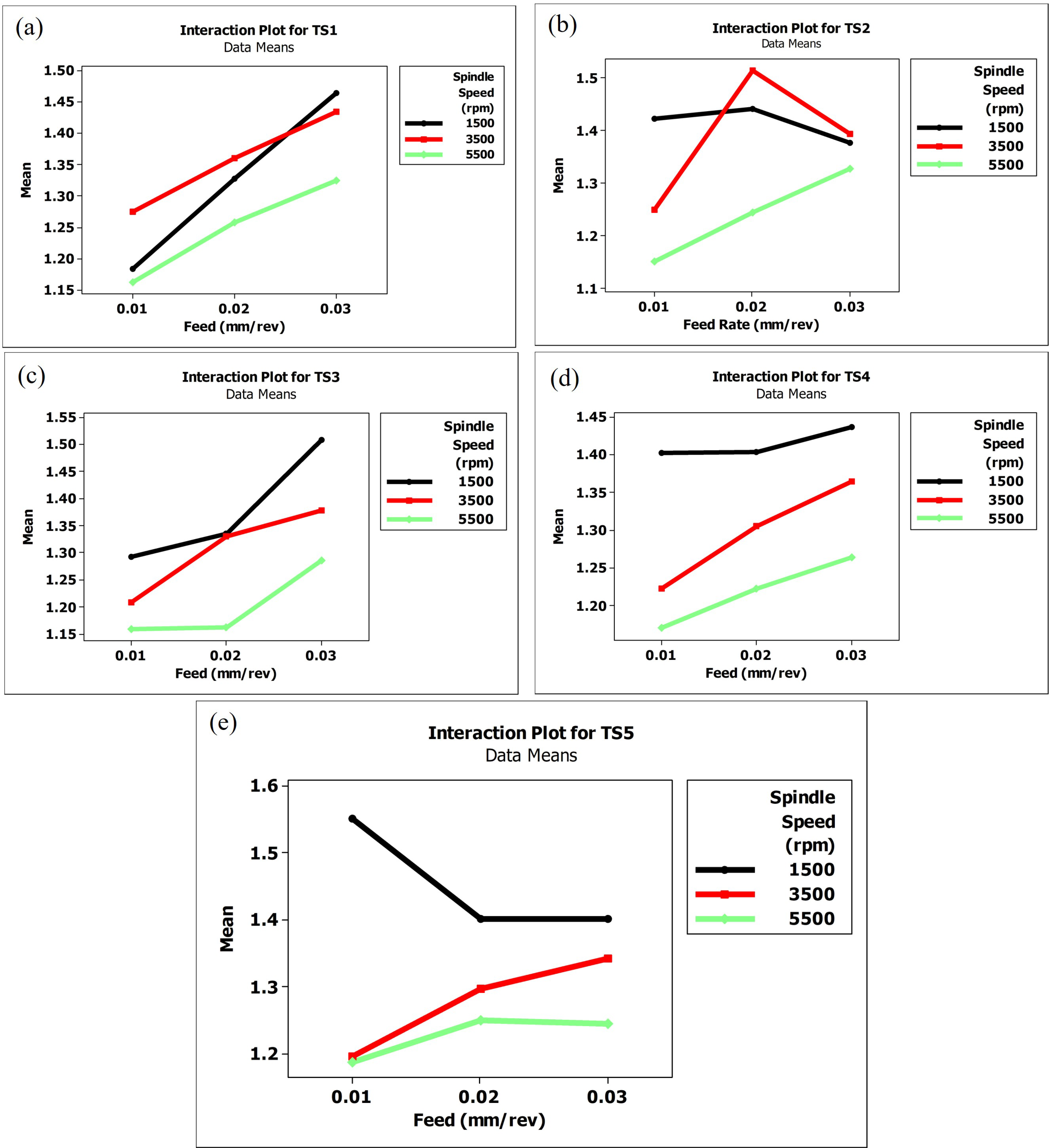
The ANOVA results, which show how much each factor contributed to the variation in the results, are shown in Table 8. The overall variability explained by each factor is shown by the adjusted sum of squares (Adj SS) and the sequential sum of squares (Seq SS). The spindle speed appears to account for the most variation, as seen by its highest Seq SS (72.9587) and Adj SS (72.9587). Figure 7 shows the effect of spindle speed and feed rate on surface roughness. They illustrate that higher spindle speed and lower feed rate result in decreased surface roughness.

3.2. Delamination Analysis

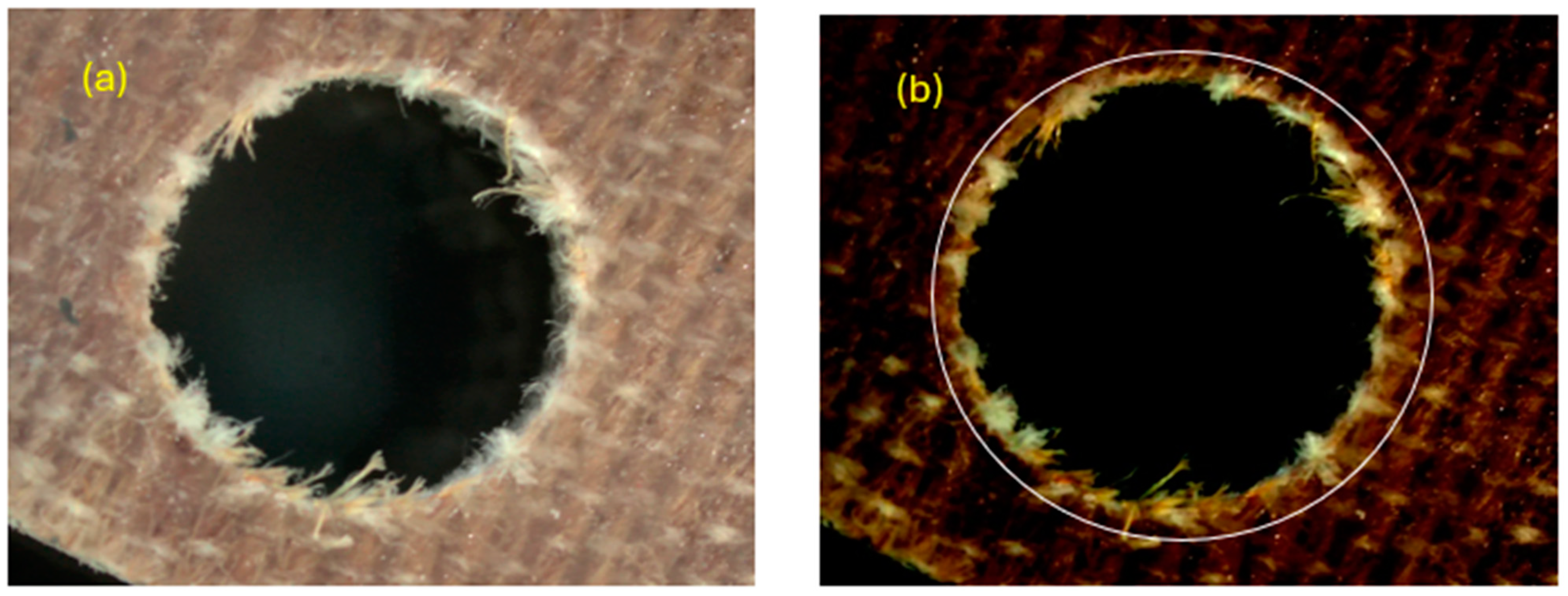
During the drilling of composites, delamination typically occurs at the entry and exit points of the drill. The entry delamination is caused by the initial contact of the drill bit with the composite surface, while exit delamination occurs as the drill bit exits the material. Both types of delamination can lead to an increase in the diameter of the hole and potential weakening of the composite structure [34]. In this study, exit delamination was measured and the results are shown in Figure 8a,b. The main effects plots are shown in Figure 9 and Figure 10. The spindle speed, feed rate, and drill type have a major impact on the quality of drilled holes in natural fiber hybrid composites according to the main effects plots for delamination. By increasing the spindle speed from 1500 rpm to 5500 rpm, the mean delamination factor decreased significantly from around 1.45 to 1.20. Higher spindle speeds may reduce cutting pressures and heat output, which could protect the composite material from damage, according to this trend. On the other hand, when the feed rate increased from 0.01 mm/rev to 0.03 mm/rev, the mean delamination factor increased from around 1.275 to 1.325. At higher feeds, inter-layer crack propagation increases, promoting more delamination [35]. This suggests that higher feed rates cause more forces and vibrations, which in turn causes greater delamination.
In terms of drill type, the step drill outperforms twist and core drills. The twist and core drills have mean delamination factors of approximately 1.32, while the step drill has a lower mean delamination factor, suggesting that it is more effective in reducing delamination. This can be explained by the geometry of the step drill, which probably generates less stress. The S/N ratios also support these conclusions, demonstrating better performance at higher spindle speeds and lower feed rates, and identifying the step drill as the more advantageous option.
Minimum delamination factor of 1.11 was observed in bamboo composite (TS2) at a speed of 5500 rpm and feed rate of 0.01 mm/rev, which also aligns with the minimum value of surface roughness. The maximum delamination factor of 1.597 was in Al2O3 composite (TS5) at 1500 rpm spindle speed and 0.01 mm/rev feed. This result aligns with various studies [36,37].
S/N ratios at various spindle speeds, feed rates, and drill type levels are shown in Table 9, which is the S/N ratio response table. The range of S/N ratios for each factor throughout the levels is represented by the Delta numbers. With the largest Delta (1.268), spindle speed is the factor that affects S/N ratios the most, suggesting its importance. The drill type has the least effect (Delta = 0.152), followed by the feed rate (Delta = 0.837). The spindle speed is confirmed as the most important factor based on the ranking depending on the Delta values, followed by the feed rate and drill type. Quantifying each factor’s statistical significance is demonstrated in Table 10. The variance attributable to each factor is given by the sequential sum of squares (Seq SS) and adjusted sum of squares (Adj SS). The highest Seq SS (2.41203) and Adj SS (2.41203) are found for spindle speed, indicating that it is mainly responsible for the variation in the S/N ratios. Figure 11 shows the interaction between spindle speed and feed rate in the case of delamination.

4. Conclusions

In this study, the delamination and surface roughness of five different ramie–bamboo-based natural fiber composite laminates incorporating epoxy and/or nano-fillers (SiC, Al2O3) for different machining parameters such as feed rate, spindle speed, and drill bit types were investigated. The following are the conclusions drawn from the current experimental study.
  • Surface roughness is mostly affected by spindle speed, followed by feed rate and drill type. Low chisel edge and progressive multi-step cutting action of step drill bits decrease burr formation, all of which contribute to smoother surfaces.
  • It is observed that as spindle speed increases, the delamination decreases and also step drills cause less delamination than twist and core drills among drill types.
  • Step drill bits are ideal for natural fiber hybrid composites due to their softness and non-abrasiveness, which result in less tool wear and smoother finishes. Synthetic composites, being abrasive, cause rapid tool wear, making them less suitable for step drill bits.
  • From observations, to achieve minimum delamination size and good surface roughness when drilling ramie–bamboo-based hybrid laminates, the optimal combination is using a step drill bit, a spindle speed of 5500 rpm, and a feed rate of 0.01 mm/rev.

Author Contributions

Conceptualization, K.K.P., S.A. and N.S.; Methodology, G.L., C.U.K.R., A.J. and N.S.; Software, S.S. and N.S.; Formal analysis, K.K.P., S.S., S.A. and N.S.; Investigation, G.L., C.U.K.R., A.J., S.A. and N.S.; Data curation, G.L., C.U.K.R. and A.J.; Writing—original draft, N.S.; Writing—review & editing, S.A. and N.S.; Visualization, S.S.; Supervision, K.K.P. and N.S. All authors have read and agreed to the published version of the manuscript.

Funding

This research received no external funding.

Data Availability Statement

Data are contained within the article.

Conflicts of Interest

The authors declare no conflict of interest.

References

  1. Syduzzaman, M.; Al Faruque, M.A.; Bilisik, K.; Naebe, M. Plant-based natural fibre reinforced composites: A review on fabrication, properties and applications. Coatings 2020, 10, 973. [Google Scholar] [CrossRef]
  2. Teja, T.R.; VenkataRao, D.; Naidu, A.L.; Bahubalendruni, M.V.A.R. Mechanical and chemical Properties of Ramie reinforced composites and manufacturing techniques: A Review. Int. J. Res. Dev. Technol. 2017, 8, 21–29. Available online: https://www.researchgate.net/publication/324058516 (accessed on 18 January 2024).
  3. Rehman, K.; Mohammad, H.; Umer, R. Biomass and Bioenergy Processing and Properties; Springer: Berlin/Heidelberg, Germany, 2014. [Google Scholar] [CrossRef]
  4. Zare, Y.; Rhee, K.Y.; Hui, D. Influences of nanoparticles aggregation/agglomeration on the interfacial/interphase and tensile properties of nanocomposites. Compos. B Eng. 2017, 122, 41–46. [Google Scholar] [CrossRef]
  5. Kumar, L.R.; Madhu, S.; Mothilal, T.; Singh, D.P.; Ali, H.M.; Kamal, M.D.R. Effect of walnut powder reinforcement on the mechanical properties of biodegradable natural flax/hemp fibre-based composites. Mater. Today Proc. 2022, 69, 1387–1393. [Google Scholar] [CrossRef]
  6. Datta, J.; Kosiorek, P.; Włoch, M. Effect of high loading of titanium dioxide particles on the morphology, mechanical and thermo-mechanical properties of the natural rubber-based composites. Iran. Polym. J. 2016, 25, 1021–1035. [Google Scholar] [CrossRef]
  7. Ashraf, M.A.; Peng, W.; Zare, Y.; Rhee, K.Y. Effects of Size and Aggregation/Agglomeration of Nanoparticles on the Interfacial/Interphase Properties and Tensile Strength of Polymer Nanocomposites. Nanoscale Res. Lett. 2018, 13, 214. [Google Scholar] [CrossRef]
  8. Prasad, K.S.; Chaitanya, G. Optimization of process parameters on surface roughness during drilling of GFRP composites using taguchi technique. Mater. Today Proc. 2020, 39, 1553–1558. [Google Scholar] [CrossRef]
  9. Prasad, K.S.; Chaitanya, G. Analysis of delamination in drilling of GFRP composites using Taguchi Technique. Mater. Today Proc. 2019, 18, 3252–3261. [Google Scholar] [CrossRef]
  10. Davim, J.P.; Rubio, J.C.; Abrao, A.M. A novel approach based on digital image analysis to evaluate the delamination factor after drilling composite laminates. Compos. Sci. Technol. 2007, 67, 1939–1945. [Google Scholar] [CrossRef]
  11. Tan, C.L.; Azmi, A.I.; Muhammad, N. Delamination and Surface Roughness Analyses in Drilling Hybrid Carbon/Glass Composite. Mater. Manuf. Process. 2016, 31, 1366–1376. [Google Scholar] [CrossRef]
  12. Zhang, H.; Chen, W.; Chen, D.; Zhang, L. Assessment of the exit defects in carbon fibre-reinforced plastic plates caused by drilling. Key Eng. Mater. 2001, 196, 43–52. [Google Scholar] [CrossRef]
  13. Nassar, M.M.A.; Arunachalam, R.; Alzebdeh, K.I. Machinability of natural fiber reinforced composites: A review. Int. J. Adv. Manuf. Technol. 2017, 88, 2985–3004. [Google Scholar] [CrossRef]
  14. Xu, J.; An, Q.; Cai, X.; Chen, M. Drilling machinability evaluation on new developed high-strength T800S/250F CFRP laminates. Int. J. Precis. Eng. Manuf. 2013, 14, 1687–1696. [Google Scholar] [CrossRef]
  15. Debnath, K.; Singh, I.; Dvivedi, A. Drilling characteristics of sisal fiber-reinforced epoxy and polypropylene composites. Mater. Manuf. Process. 2014, 29, 1401–1409. [Google Scholar] [CrossRef]
  16. Geier, N.; Póka, G.; Jacsó, Á.; Pereszlai, C. A method to predict drilling-induced burr occurrence in chopped carbon fibre reinforced polymer (CFRP) composites based on digital image processing. Compos. B Eng. 2022, 242, 110054. [Google Scholar] [CrossRef]
  17. Kumar, J.; Singh, Y.; Rakesh, P.K.; Singh, I.; Davim, J.P. The Impact of Hole Diameter on the Molded and Drilled Holes in Jute-Fiber-Reinforced Epoxy Composites. J. Compos. Sci. 2023, 7, 376. [Google Scholar] [CrossRef]
  18. Debnath, K.; Singh, I.; Dvivedi, A. On the analysis of force during secondary processing of natural fiber-reinforced composite laminates. Polym. Compos. 2017, 38, 164–174. [Google Scholar] [CrossRef]
  19. Kerrigan, K.; Scaife, R.J. Wet vs dry CFRP drilling: Influence of cutting fluid on tool performance. Procedia CIRP 2018, 77, 315–319. [Google Scholar] [CrossRef]
  20. Patel, K.; Gohil, P.P.; Chaudhary, V. Investigations on drilling of hemp/glass hybrid composites. Mater. Manuf. Process. 2018, 33, 1714–1725. [Google Scholar] [CrossRef]
  21. Brahmbhatt, K.; Patel, K.; Bhargav, H. Investigations on Drilling Characteristics of Glass-Bamboo Reinforced Hybrid Composites. Educ. Adm. Theory Pract. 2024, 30, 3122–3127. [Google Scholar] [CrossRef]
  22. Chandrabakty, S.; Renreng, I.; Djafar, Z.; Arsyad, H. Experimental study and investigation of thrust force and delamination damage of drilled ramie woven reinforced composites. Int. J. Automot. Mech. Eng. 2020, 17, 7618–7628. [Google Scholar] [CrossRef]
  23. Ahmed, K.S.; Kumar, A.S. An Experimental Study on Drilling of Jute/Epoxy Composites with Ceramic Fillers. J. Eng. Res. Appl. 2018, 59–67. [Google Scholar]
  24. Nasir, A.A.A.; Azmi, A.I.; Lih, T.C.; Shuaib, N.A. Experimental study towards determination of critical feed for minimization of delamination damage in drilling flax natural fibre composites. Procedia CIRP 2018, 77, 191–194. [Google Scholar] [CrossRef]
  25. Ramesh, V.; Karthik, K.; Cep, R.; Elangovan, M. Influence of Stacking Sequence on Mechanical Properties of Basalt/Ramie Biodegradable Hybrid Polymer Composites. Polymers 2023, 15, 985. [Google Scholar] [CrossRef]
  26. Kumar, R.; Ganguly, A.; Purohit, R. Optimization of mechanical properties of bamboo fiber reinforced epoxy hybrid nano composites by response surface methodology. Int. J. Interact. Des. Manuf. 2023, 1–14. [Google Scholar] [CrossRef]
  27. Shahabaz, S.M.; Mehrotra, P.; Kalita, H.; Sharma, S.; Naik, N.; Noronha, D.J.; Shetty, N. Effect of Al2O3 and SiC Nano-Fillers on the Mechanical Properties of Carbon Fiber-Reinforced Epoxy Hybrid Composites. J. Compos. Sci. 2023, 7, 133. [Google Scholar] [CrossRef]
  28. Geier, N.; Davim, J.P.; Szalay, T. Advanced cutting tools and technologies for drilling carbon fibre reinforced polymer (CFRP) composites: A review. Compos. Part A Appl. Sci. Manuf. 2019, 125, 105552. [Google Scholar] [CrossRef]
  29. Ahmed, Y.S.; Fox-Rabinovich, G.; Paiva, J.M.; Wagg, T.; Veldhuis, S.C. Effect of built-up edge formation during stable state of wear in AISI 304 stainless steel on machining performance and surface integrity of the machined part. Materials 2017, 10, 1230. [Google Scholar] [CrossRef] [PubMed]
  30. Shahabaz, S.M.; Shetty, N.; Sharma, S.; Jayashree, P.K.; Shetty, S.D.; Naik, N. Optimization of drilling parameters on delamination and burr formation in drilling of neat CFRP and hybrid CFRP nano-composites. Mater. Res. Express 2024, 11, 035006. [Google Scholar] [CrossRef]
  31. Rashid, K.M.J. Optimize the Taguchi method, the signal-to-noise ratio, and the sensitivity. Int. J. Stat. Appl. Math. 2023, 8, 64–70. [Google Scholar] [CrossRef]
  32. Xu, J.; Lin, T.; Davim, J.P.; Chen, M.; El Mansori, M. Wear behavior of special tools in the drilling of CFRP composite laminates. Wear 2021, 476, 203738. [Google Scholar] [CrossRef]
  33. Wang, C.; Cheng, K.; Rakowski, R.; Greenwood, D.; Wale, J. Comparative studies on the effect of pilot drillings with application to high-speed drilling of carbon fibre reinforced plastic (CFRP) composites. Int. J. Adv. Manuf. Technol. 2017, 89, 3243–3255. [Google Scholar] [CrossRef]
  34. Singh, A.P.; Sharma, M.; Singh, I. A review of modeling and control during drilling of fiber reinforced plastic composites. Compos. B Eng. 2013, 47, 118–125. [Google Scholar] [CrossRef]
  35. Heidary, H.; Karimi, N.Z.; Minak, G. Investigation on delamination and flexural properties in drilling of carbon nanotube/polymer composites. Compos. Struct. 2018, 201, 112–120. [Google Scholar] [CrossRef]
  36. Shadrach, A.; Sekaran, J.; Kumar, K.P. Study on Drilling of Woven Sisal and Aloevera Natural Fibre Polymer Composite. Mater. Today Proc. 2019, 16, 640–646. Available online: www.sciencedirect.com (accessed on 2 February 2024). [CrossRef]
  37. Pankaj; Jawalkar, C.; Kant, S. Study on Mechanical Properties and Delamination Factor Evaluation of Chemically Treated Nettle Fiber Reinforced Polymer Composites. J. Nat. Fibers 2023, 20, 2135053. [Google Scholar] [CrossRef]
Figure 1. Drilling experimental setup.
Jmmp 08 00195 g001
Figure 2. Different types of drill bits: (a) twist drill, (b) step drill, and (c) core drill.
Jmmp 08 00195 g002
Figure 3. Optical microscope for capturing images to measure delamination.
Jmmp 08 00195 g003
Figure 4. Surface roughness measuring instrument.
Jmmp 08 00195 g004
Figure 5. Main effects plot for mean surface roughness.
Jmmp 08 00195 g005
Figure 6. Main effects plot for S/N ratios for surface roughness.
Jmmp 08 00195 g006
Figure 7. Surface roughness vs. feed at various speeds: (a) interaction plot of TS1, (b) interaction plot of TS2, (c) interaction plot of TS3, (d) interaction plot of TS4, and (e) interaction plot of TS5.
Jmmp 08 00195 g007
Figure 8. (a) Original image. (b) Image after decreasing brightness.
Jmmp 08 00195 g008
Figure 9. Main effects plot for S/N ratios for delamination factor.
Jmmp 08 00195 g009
Figure 10. Main effects plot for means for delamination factor.
Jmmp 08 00195 g010
Figure 11. Delamination vs. feed at various speeds: (a) interaction plot of TS1, (b) interaction plot of TS2, (c) interaction plot of TS3, (d) interaction plot of TS4, and (e) interaction plot of TS5.
Jmmp 08 00195 g011
Table 1. General properties of fiber mats [25,26].
MaterialTensile Strength (MPa)Young’s Modulus (GPa) Density
(g/cm3)
Diameter
(mm)
Cellulose (%)Lignin (%)Type
Ramie180–2101.31.50.2868.60.6Woven
Bamboo18014.20.3–0.50.3473.810Woven
Table 2. Properties of materials used in laminates [27].
MaterialDensity
(g/cm3)
Size
(nm)
Color
Epoxy Resin1.2-Transparent
Al2O33.920–30White
SiC3.250Grey
Table 3. Composition of laminates.
Test Specimen
Configuration
Laminate
Configuration
Fiber (wt%)Epoxy (wt%)Nano Filler
(wt%)
TS1RRRRRRRR3070-
TS2BBBBBBBB3070-
TS3RBRBBRBR3070-
TS4RBRBBRBR + Al2O330682
TS5RBRBBRBR + SiC30682
R: Ramie; B: Bamboo.
Table 4. Machining parameters for drilling.
Sl. No. Parameters
Spindle Speed (rpm)Feed
(mm rev−1)
Drill Type
115000.01Twist
235000.02Step
355000.03Core
Table 5. L27 orthogonal array for delamination factor.
Spindle Speed
(rpm)
Feed
(mm rev−1)
Drill TypeTS1TS2TS3TS4TS5
15000.01Twist1.1731.5641.3121.3841.534
15000.01Twist1.2151.3341.2651.3251.524
15000.01Twist1.1641.3671.2981.4971.597
15000.02Step1.2741.5141.3431.3981.454
15000.02Step1.3061.4371.3651.4641.398
15000.02Step1.4011.3701.2981.3471.354
15000.03Core1.4741.2171.5561.5201.435
15000.03Core1.4561.5001.4651.3651.354
15000.03Core1.4651.4101.5081.4241.414
35000.01Step1.2531.2451.1651.2681.217
35000.01Step1.3021.2671.2051.2451.204
35000.01Step1.2681.2341.2541.1541.165
35000.02Core1.3451.4971.2401.3251.198
35000.02Core1.3481.5041.3451.2681.335
35000.02Core1.3881.5401.4041.3241.354
35000.03Twist1.4091.4001.3801.4051.314
35000.03Twist1.4851.3501.4001.3851.334
35000.03Twist1.4121.4271.3541.3041.375
55000.01Core1.1541.1101.1701.1371.145
55000.01Core1.1631.1901.1141.1781.198
55000.01Core1.1681.15001.1901.1941.214
55000.02Twist1.2031.2451.1351.1971.235
55000.02Twist1.2631.2261.1651.2671.227
55000.02Twist1.3081.2601.1841.2041.287
55000.03Step1.2651.3241.2741.2981.254
55000.03Step1.3031.2981.2851.2471.264
55000.03Step1.4081.3561.2981.2451.214
Table 6. L27 orthogonal array for surface roughness (µm).
Spindle Speed
(rpm)
Feed
(mm rev−1)
Drill TypeTS1TS2TS3TS4TS5
15000.01Twist3.853.553.423.413.82
15000.01Twist3.593.763.513.323.6
15000.01Twist3.313.493.193.633.14
15000.02Step3.112.782.843.943.63
15000.02Step3.282.972.683.513.84
15000.02Step2.912.572.463.83.75
15000.03Core3.763.313.474.423.57
15000.03Core3.983.423.634.253.77
15000.03Core4.193.544.633.843.95
35000.01Step2.682.582.243.12.91
35000.01Step2.482.192.132.792.85
35000.01Step2.822.432.473.032.72
35000.02Core3.563.163.643.623.89
35000.02Core3.793.243.773.714.05
35000.02Core3.923.363.883.973.95
35000.03Twist3.183.123.463.423.66
35000.03Twist3.243.293.533.613.42
35000.03Twist3.413.393.623.553.12
55000.01Core1.211.121.231.171.19
55000.01Core1.241.281.261.231.29
55000.01Core1.351.351.341.311.35
55000.02Twist1.511.411.451.541.56
55000.02Twist1.621.521.561.671.63
55000.02Twist1.731.641.671.721.76
55000.03Step2.272.172.212.332.31
55000.03Step2.362.272.322.432.42
55000.03Step2.582.492.532.662.57
Table 7. Response table for S/N ratios for surface roughness.
LevelSpindle Speed (rpm)Feed
(mm rev−1)
Drill Type
1−10.957−7.112−8.550
2−10.159−8.566−8.753
3−4.558−9.991−8.370
Delta6.3992.8850.383
Rank123
Table 8. Analysis of variance for S/N ratios for surface roughness.
SourceDFSeq SSAdj SSAdj MSFp Value
Spindle speed (rpm)272.958772.958736.47937.870.113
Feed
(mm rev−1)
212.483912.48396.24201.350.426
Drill type20.22030.22030.11020.020.977
Residual Error29.27239.27234.6361
Total894.9352
Table 9. Response table for S/N ratios for delamination factor.
LevelSpindle Speed
(rpm)
Feed
(mm rev−1)
Drill Type
1−3.042−1.970−2.460
2−2.438−2.478−2.321
3−1.774−2.807−2.473
Delta1.2680.8370.152
Rank123
Table 10. Analysis of variance for S/N ratios for delamination factor.
SourceDfSeq SSAdj SSAdj MSFp Value
Spindle speed22.412032.412031.2060225.190.038
Feed21.065691.065690.5328411.130.082
Drill type20.042470.042470.021230.440.693
Residual
error
20.095740.095740.04787
Total83.61593
Disclaimer/Publisher’s Note: The statements, opinions and data contained in all publications are solely those of the individual author(s) and contributor(s) and not of MDPI and/or the editor(s). MDPI and/or the editor(s) disclaim responsibility for any injury to people or property resulting from any ideas, methods, instructions or products referred to in the content.