Article

Study on Extraordinarily High-Speed Cutting Mechanics and Its Application to Dry Cutting of Aluminum Alloys with Non-Coated Carbide Tools

1
Graduate School of Engineering, Nagoya University, Furo-cho, Chikusa-ku, Nagoya 464-8603, Aichi, Japan
2
Boeing Research and Technology, The Boeing Company, MC 5A-08, Seattle, WA 98124-2207, USA
*
Author to whom correspondence should be addressed.
J. Manuf. Mater. Process. 2024, 8(5), 198; https://doi.org/10.3390/jmmp8050198
Submission received: 12 August 2024 / Revised: 31 August 2024 / Accepted: 2 September 2024 / Published: 13 September 2024

Abstract

:
The friction/adhesion between the tool and chip is generally large in metal cutting, and it causes many problems such as high cutting energy/rough surface finish. To suppress this, cutting fluid and tool coating are used in practice, but they are high in energy/cost and environmentally unfriendly. Therefore, this paper investigates the extraordinarily high-speed cutting (EHS cutting) mechanics of mainly soft and highly heat-conductive materials and proposes their application to solve the friction/adhesion problem in an environmentally friendly manner. In order to clarify the EHS cutting mechanics, a simple analytical model is constructed and experiments are conducted with measurement of the cutting temperature and forces. As a result, the following points are clarified/found: (1) heat softening at the secondary plastic deformation zone rather than the primary plastic deformation zone, (2) friction coefficient drop to 0.170 in EHS cutting, and (3) gradually increasing trend of cutting temperature in EHS cutting. Finally, EHS cutting is applied to dry cutting of aluminum alloys with a non-coated carbide tool and compared to conventional wet cutting with a DLC-coated carbide tool, and it is shown that a coating/coolant can be omitted in this region to achieve environmentally friendly cutting.

1. Introduction

In the cutting of metallic materials such as aluminum alloys, copper alloys, and ferrous materials, friction between the tool and chip is generally large, and the workpiece material adheres easily to the cutting edge [1], which can cause various issues. For example, the adhered workpiece material, i.e., built-up edge, can deteriorate the machined surface due to its growth and drop. In addition, the friction force increases the resultant force and energy and decreases the machining accuracy. This high friction force is caused by the high compressive force and high friction coefficient between the rake face and the chip. The reason for the high compressive force is that a large force is required for the generation of the chip by plastic deformation of the workpiece in the primary plastic deformation zone, as shown in Figure 1 [2]. On the other hand, the reason for the high friction coefficient is that the rake face contacts the newly formed material surface, which is chemically active and adhesive. Regarding heat softening due to the cutting temperature, studies in the literature have focused on the primary plastic deformation zone, i.e., shear zone, based on the Johnson–Cook model [3,4]. However, as shown in the representative temperature distribution in Figure 1, the shear zone does not become that hot, whereas the tool–chip interface, especially above the secondary plastic deformation zone, is much hotter than the shear zone. This is because most of the shear heat generated in the shear zone and the frictional heat generated in the tool–chip interface flow into the chip together with the material flow at relatively high cutting speeds [2]. To the authors’ understanding, it is difficult to reduce the compressive force significantly because of this fact. As shown in Figure 1, the shear heat generated in the shear zone increases the chip temperature almost uniformly after the shear zone, and the friction heat generated in the tool–chip interface further increases the temperature locally at the interface.
Contrarily, many methods to reduce the friction coefficient were proposed/developed in the literature. Examples of conventional methods to suppress the adhesion and reduce the friction coefficient are providing cutting fluid, applying low-friction coating on the tool surface, and using diamond-based tools such as polycrystalline diamond (PCD) tools. Especially in aluminum alloy machining, adhesion is a major issue, and cutting fluid and low-friction coating are usually used simultaneously [5]. However, supplying cutting fluid not only increases the machining cost including the surrounding equipment, but also the energy consumption [6,7]; additionally, the post-treatment of the used fluid imposes an environmental burden. Minimum-quantity lubrication (MQL) was proposed to reduce the amount of cutting fluid [8], but there are still concerns that the mist produced by MQL affects the human body and environment. Another research is cryogenic cutting using liquified CO2 or N2 [9], but there are practical issues. Tool coating and PCD tools provide some lubricating effect on the rake face, but they increase tool cost and have practical issues such as delamination of the coating and chipping of the PCD tool.
Other advanced cutting technologies such as high-pressure coolant systems and laser-assisted machining to improve the cutting performance exist in the literature, but the energy consumption is extremely large for them, e.g., over ten kilo-Watts for the former technology [10] and several hundreds of Watts to over ten kilo-Watts for the latter technology [11]. Although effects such as extreme cooling and enhanced chip disposability for the former technology and heat softening for the latter technology may be achieved, the obtained improvements force too much environmental load.
Meanwhile, as shown in Figure 1, a high-temperature region is generated in the tool–chip interface by the friction at the interface in addition to the shear in the shear zone. The friction heat can be increased, for example, by increasing the cutting speed, and it should also affect the friction coefficient. In fact, the drop in the friction coefficient was found through experiments in some studies [12,13,14]. However, the mechanism of this drop is still somewhat unclear in the literature. Recht claimed that the reason for this drop is the melting of the asperities of the workpiece at the tool–chip interface [15]. From a different point of view, Wang et al. argue that workpiece embrittlement and/or decreasing adhesion at this surface may be responsible for the drop [16]. On the other hand, the authors have a slightly different perspective: the occurrence of melting should depend mainly on the material even at extremely high speed, and heat softening in the secondary plastic deformation zone should be responsible for the friction coefficient drop in those cases where melting does not occur. Note that the term “melting” is used to refer to partial melting where part of the alloy begins to melt at the solidus temperature of that alloy. The drop also indicates that the compressive force on the rake face does not drop so much, which corresponds to the above-mentioned fact, i.e., the tool–chip interface becomes much hotter than the shear zone. For example, it was confirmed through experiments that the tool–chip interface temperature of difficult-to-cut materials, e.g., Ti-6Al-4V and Inconel 718 alloy, almost reached their melting points at high cutting speeds [17]. On the other hand, aluminum alloys are relatively soft and highly heat-conductive, and melting should be difficult; in fact, the melting point was not reached [17]. Note that a ceramic tool (Al2O3) with a relatively dull cutting edge and low heat conductivity was used in these experiments. Other studies conducted cutting of aluminum alloys at cutting speeds of over 4750 m/min [4,18], but they did not collect the data of the cutting temperature at the tool–chip interface and did not confirm/discuss the drop of the friction coefficient. In summary, the authors believe that the following points have not been clarified yet in the literature: (1) the fact that heat softening must be considered in the secondary plastic deformation zone rather than the primary plastic deformation zone, (2) reason and supporting data for the friction coefficient drop in relatively soft and highly heat-conductive materials such as aluminum alloy, and (3) characteristics of the temperature rise at the tool–chip interface at high speeds in those materials. They all contribute to the clarification of the cutting mechanics at high cutting speeds.
In this paper, the mechanics of extraordinarily high-speed cutting (EHS cutting), in which the tool–chip interface temperature is high enough to reach the softening/melting point of the workpiece material, are investigated. To better understand the mechanics and affecting parameters of EHS cutting, a simple analytical model is constructed to estimate the cutting temperature in the EHS cutting region, and experiments are conducted against aluminum alloy along with the measurement of the average cutting temperature and forces. In the experiments, the effects of the cutting speed, feed per revolution, and rake angle are evaluated, and a friction coefficient drop to 0.170 is confirmed in the EHS cutting region. The measured cutting temperature shows a gradually increasing trend in this region, which agrees with the estimated one, and it is confirmed that the heat softening occurs in the secondary plastic deformation region rather than the primary plastic deformation region. Furthermore, it is applied to dry cutting utilizing non-coated carbide tools; the cutting fluid and tool coating have no meaning in EHS cutting and can be eliminated, realizing environmentally friendly cutting.

2. Mechanics/Application of Extraordinarily High-Speed Cutting and Analysis of Cutting Temperature in EHS Cutting

2.1. Understanding of Mechanics and Application to Dry Cutting of Aluminum Alloy with Non-Coated Tool

To begin with, experimental results from the literature and results from the present paper are further examined here. Figure 2 shows the relationship between the cutting speed and the cutting temperature at the tool–chip interface when machining various materials by a ceramic tool with a rake angle of −8 deg, which was summarized by Ueda et al. [19]. The cutting temperature is measured by a two-color pyrometer in which the sensing surface of the optical fiber is directed towards the rake face near the cutting edge, that is, the temperature close to the highest temperature is detected according to its measurement principle [20]. The solid lines indicate the predicted results of the cutting temperature with the assumption that it is proportional to the 0.5-th power of the cutting speed. Note that this exponent was derived by dimensional analysis [19]. As shown in the figure, the behavior of the cutting temperature differs depending on the type of the material. Ti-6Al-4V exhibits two trends: at a cutting speed below 400 m/min, the temperature has a power function trend and rapidly rises close to the melting point of the material as shown by the solid line, and then it saturates slightly below the melting point as shown by the broken line. In contrast, aluminum alloy and steel exhibit a similar former trend, but the latter trend differs greatly; their melting points are not reached and a dull rising behavior can be exhibited.
Correlated to these results, the relationship between the specific cutting energy k s = F p / b f , which is the energy necessary to cut a unit volume of the material, and the specific melt-beginning energy q c = ρ c θ m , which is the energy needed to heat the material per unit volume to its melting point, is shown in Figure 3. Here, F p is the principal cutting force, b is the cutting width, f is the feed per revolution (uncut chip thickness), ρ is the density of the workpiece material, c is the specific heat capacity of the workpiece material, and θ m is the melting point of the material. k s of aluminum alloy (7050-T7451) with a carbide tool is identified from the experiments in this paper, and those of Ti-6Al-4V with an alumina tool [21], C45 with a carbide tool [22], and Inconel 718 with a SiAlON tool [23] are cited from the literature. Note that the term “melt-beginning energy” refers to the energy needed to raise the temperature of the material to the solidus temperature where partial melting of the alloy begins. For simplicity, the term “melting point” will be used instead of “solidus temperature” to understand the image. From Figure 3, it can be observed that k s and q c are close values for each case, but the behavior during cutting differs from the relationship between them; the authors believe that this relationship is important to categorize the high-speed cutting according to their behaviors mainly depending on the workpiece material and to investigate its effect on the machining regime. Note that the behavior is also dependent on tool properties such as heat conductivity and geometry.
In the cutting in the region of k s > q c , e.g., Ti-6Al-V with a dull alumina tool, the cutting temperature rises to the melting point and saturates along with the increase in the cutting speed, as shown in Figure 2. Even if more cutting energy is input by increasing the cutting speed, the temperature cannot be increased further since melting has been achieved, which requires incremental energy. This melting was the idea that Recht mentioned [15].
On the other hand, the cutting temperature of materials in the region of k s < q c , e.g., aluminum alloy with a sharp carbide tool, does not rise to the melting point, which is also shown in Figure 2. This is because the chip temperature cannot reach the melting point since the specific cutting energy is not sufficient even if 100% of it flows into the chip, and the temperature gradient cannot be large enough due to high heat conductivity. However, it needs to be pointed out that the temperature of the shear zone is not that high; even if more cutting energy is input, the shear zone temperature does not increase since almost all of the shear heat and friction heat flow into the chip at high speeds. In such a situation, the heat softening at the tool–chip interface needs to be considered rather than softening in the shear zone for correct consideration of the cutting mechanics at these speeds. For this reason, the compressive force should not decrease much, whereas the friction force should decrease largely; the friction coefficient decreases. Note that the tool–chip interface temperature in the region of k s < q c does not saturate but increases gradually with the increase in the cutting speed; see the aluminum alloy with a carbide tool in Figure 2. This is because the chip flow or friction speed increases, and the temperature gradient increases gradually.
In this research, the region of k s > q c is called the melt-lubricating region, and that of k s < q c is called the heat-softening region; see Figure 3. In addition, the cutting at which the tool–chip interface temperature saturates to the melting point or the power function trend becomes a gradual increase is called extraordinarily high-speed cutting (EHS cutting). Note that the boundary between the two regions can move depending on the pressure, heat conductivity, speed, and low-melting-point inclusions. High pressure generally increases the melting point [24], and high heat conductivity decreases the temperature gradient in the chip; both decrease the occurrence of melting and the heat-softening region spreads. On the other hand, high speed increases the temperature gradient, and low-melting-point inclusions, e.g., Pb, Bi, and CaO, begin melting under the melting point of the alloy and cause lubrication; the melt-lubricating region spreads. As mentioned repetitively, the melting or heat softening of the material, especially in the tool–chip interface, has a great effect on the EHS cutting mechanics. Note that parameters other than the cutting speed affect the cutting temperature, e.g., feed per revolution (uncut chip thickness), rake angle of the tool, and thermal characteristics of the tool/workpiece (thermal conductivity for continuous cutting and thermal diffusivity for intermittent cutting). However, the cutting speed has the largest effect, and hence, the categorization naming is based on the term “speed”.
Meanwhile, the degree of heat softening is another point of interest. To discuss this point, the temperature dependency of the ultimate tensile strength of Al-Zn-Mg (7000 series) aluminum alloys is shown in Figure 4 [25,26]. These alloys are commonly used in aircraft structural parts, in which their hardness is increased by age-hardening at room temperature. As shown in the figure, the strength decreases against the temperature, and above 350 °C, the strength drops to less than 10% of that of the room temperature. For reference, the solidus temperature of this alloy is 490 °C [27], and its strength is less than 5% of that of the room temperature. To simply evaluate the degree of heat softening, the average cutting temperature is estimated under the assumption that all of the cutting energy is used for heating the chip in EHS cutting, that is, this temperature can be calculated by dividing the specific cutting force in the cutting-speed direction K p by the product of the density ρ and specific heat capacity c of the targeted alloy in this paper (7050-T7451). The parameters shown in Table 1 are utilized where the specific cutting force is obtained in the experiments in this paper and properties of the material are obtained from the literature [28,29]. The calculated average cutting temperature rise is 262.48 °C; the strength of the material at the tool–chip interface reduces greatly according to Figure 4, resulting in a great decrease in the friction force. Note that it is expected for the temperature of the tool–chip interface to be much hotter than this temperature because of the large temperature gradient at high speed, and the shear zone temperature is expected to be smaller than this temperature because of the heat flow into the chip together with the material flow. A more accurate temperature estimation in EHS cutting is conducted in the next chapter. If such a large decrease in the friction force is successively achieved in the EHS cutting of aluminum alloys, there is a possibility that the cutting fluid and coating can be eliminated. This should greatly contribute to carbon-neutral manufacturing, and its feasibility will be investigated in the experiments of this paper.

2.2. Analysis of Cutting Temperature in EHS Cutting of Heat-Softening Region

In order to investigate the EHS cutting phenomenon in the heat-softening region more deeply, the measured cutting temperature is compared with a simplified theoretical value using the measured force, chip thickness, and chip contact length. For simplicity, it is assumed here that during EHS cutting, 100% of the shear heat and friction heat flow into the chip, which is a reasonable assumption at high cutting speeds [30]. Another assumption is that the chip thickness is large enough to apply Jaeger’s solution (34) for a moving heat source (friction heat) on a semi-infinite body (chip) [31] since the friction heat hardly reaches the free surface of the chip at high speed, as shown in Figure 1. Under these assumptions, the average cutting temperature θ ¯ at the tool–chip interface can be calculated by the following equation:
θ ¯ θ 0 + θ ¯ s + θ ¯ f = θ 0 + U s ρ c V c f b + 1.064 U f λ a b K a 2 V f = θ 0 + F r cos ϕ + β α cos α ρ c f b cos ϕ α + 1.064 F r sin β K V c sin ϕ cos ϕ α λ b 2 a
Here, θ 0 is the ambient temperature, Δ θ ¯ s is the temperature increase by the shear deformation in the shear zone, Δ θ ¯ f is the temperature increase by the friction in the tool–chip interface, U s is the shear energy per unit time, U f is the friction energy per unit time, V c is the cutting speed, V f is the speed of chip flow, f is the feed per revolution, b is the cutting width, a is the chip contact length, ρ is the density of the workpiece, c is the specific heat capacity of the workpiece, λ is the thermal conductivity of the workpiece, K is the thermal diffusivity of the workpiece, F r is the resultant cutting force, ϕ is the shear angle, β is the friction angle, and α is the rake angle. The resultant cutting force and friction angle are calculated from the measured cutting forces (principal force F p and thrust force F t ), i.e., F r = F p 2 + F t 2 , β = tan 1 F t / F r + α in which the latter one also uses the rake angle α = 10   d e g . The shear angle is calculated from the measured chip thickness t and uncut chip thickness f using the rake angle, i.e., ϕ = tan 1 γ cos α 1 γ sin α in which the cutting ratio γ = f / t , and the chip contact length is measured from direct observation of the rubbed mark on the rake face after cutting, which is 0.43 mm. The ambient temperature is set to 20 °C (room temperature). The analyzed results will be compared and discussed with the experimental results. Note that Equation (1) can be obtained by transforming the model proposed by Loewen and Shaw [32] with the same assumptions.

3. Experimental Method

Turning experiments are conducted to investigate the mechanics of EHS cutting and the possibility of its application to dry cutting of aluminum alloys. In these experiments, the average cutting temperature is measured by the tool–workpiece thermocouple method, and the cutting forces are measured to mainly evaluate the friction coefficient. A precise explanation of the components of the experiments follows in the rest of this chapter.

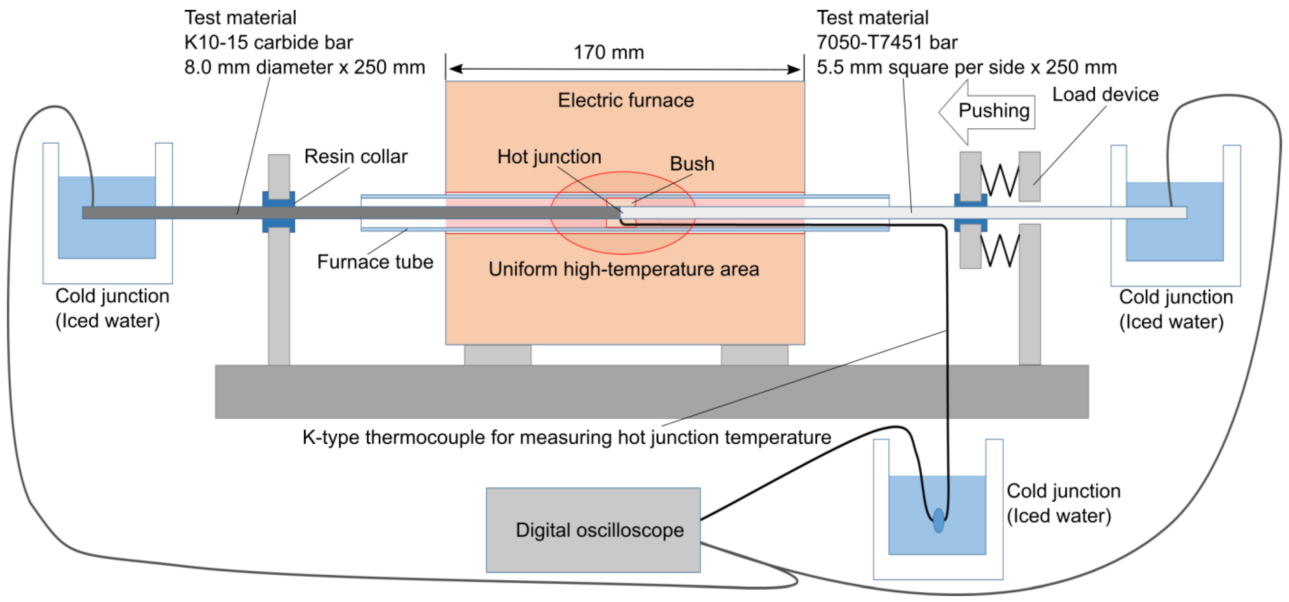
3.1. Thermoelectromotive Force Calibration

The classical tool–workpiece thermocouple method is employed to measure the cutting temperature [33], and the thermoelectromotive force (TEMF) generated between the tool and workpiece is measured. The test material of the workpiece side is the same as that used in the cutting experiment. The test material of the tool side is K10-15-type alloy (MD10, Tungaloy Corp., Iwaki, Japan) with approximately the same cobalt content rate and tungsten carbide grain size as that used in the cutting experiment. The experimental setup is shown in Figure 5. The test material of the tool side is fixed and pressed by the load device from the workpiece side. To measure the true temperature at the hot junction, a K-type thermocouple is placed near that junction in the center of the electric furnace. The measured calibration curve is shown in Figure 6, and the approximated second-order polynomial is used in the experiments.

3.2. Experimental Setup and Conditions

Intermittent end-face turning experiments, which imitates the practical milling process, are conducted to investigate into the EHS cutting mechanics. Figure 7 and Figure 8 show a photograph and schematic of the experimental setup, respectively, where a CNC turning center (LB3000 EX, OKUMA Corp., Oguchi, Japan) is used in a spindle speed range of 6 to 5000 min−1.
The workpiece is 7050-T7451 aluminum alloy, whose thickness (equal to the cutting width) is 6.4 mm and chord length is 80 mm. Two ends of the workpiece are cut in one revolution, and the workpiece is sufficiently rigid in the cutting and depth-of-cut directions and fixed to the lathe chuck via a fixture. Two types of fixtures shown in Table 2 are designed depending on the cutting/rotational speed. The fixtures are specially manufactured for extraordinarily high-speed cutting; the balance quality grades are less than G2.5 at 5000 min−1 with balance-adjustable bolts. The cutting angle range shown in Table 2 is the angle range at which one end of the workpiece is machined in one revolution, and it is used later on to calculate the average force/temperature in one revolution. Note that the smaller value corresponds to the larger workpiece diameter, e.g., the cutting angle range of 26.1 deg of the large fixture corresponds to the workpiece diameter of 354 mm.
The insert material is K05-type super micro-grain cemented carbide (KS05F, Tungaloy Corp.), which is commonly used for the cutting of aluminum alloys. The cutting tool is also sufficiently rigid and fixed to the turret via a dynamometer (9257B, Kistler Holding AG, Winterthur, Switzerland). Four types of tools with different rake angles and coatings shown in Table 3 are designed for the experiments combining three types of holders (Tungaloy Corp.) and four types of inserts. Note that the clearance angle is made constant by the combination of the inserts and holders. There are no chip breakers on the rake face, and the non-coated tool is lapped to be a mirror surface to have a sharp cutting edge. The coating is a diamond-like carbon (DLC) type (AC-X∙W, ONWARD GIKEN Co., ltd, Nomi, Japan), and the coating thickness is set as 1 µm. To exclude the individual differences in the roundness of the cutting edge, only a single insert is used for each tool. Note that tool wear can be ignored in the experiments since aluminum alloy causes only small wear.
The cutting temperature and cutting forces are measured/evaluated, and values such as the average friction coefficient and average shear stress at the shear plane are calculated. The cutting temperature is achieved by the measured TEMF between the tool and workpiece; see Figure 7 and Figure 8, and the calibration curve shown in Figure 6. A brass shaft mounted on the workpiece contacts a fixed brass plate mounted on a steel plate attached to the tailstock. The shunt resistor is placed at room temperature and surrounded by aluminum foil to suppress the effect of peripheral electromagnetic radiation. The internal resistance between the tool side and workpiece side is r  = 4.3   Ω , and the shunt resistance is R = 100 Ω. The measured voltage data V are converted to the TEMF by considering both resistance values, i.e., T E M F = 1 + r R V . To eliminate the motor-relevant noise on the measured TEMF, the workpiece/tool is insulated from the spindle/turret by sandwiching bakelite sheets on their contact surfaces, and the turret is grounded. Contact of different metals other than between the tool-and-workpiece combination occurs between the carbide insert and steel holder, steel holder and brass cable, aluminum workpiece and brass shaft, and brass plate and steel plate, but the effect of the temperature rise at these contact surfaces is suppressed as much as possible by using only the first few revolutions of the cutting data, where only the vicinity of the cutting point is heated up. Note that the distribution of the heat/temperature and shear stress at the shear plane and tool–chip interface affect the cutting process, but their averaged values are still valuable to understand the mechanics from a broad perspective.
The experimental conditions shown in Table 4 are used in the experiments. Four types of experiments are conducted to investigate EHS cutting. Firstly, the cutting speed is varied using tool T1 to verify the behavior in the EHS cutting of aluminum alloys. The cutting speed is varied from 70 to 5184 m/min, where the upper limit is based on the maximum spindle speed (33,000 min−1) of the latest high-speed machine tools for aircraft aluminum parts and a large-diameter cutter (e.g., 50 mm) practically used in such machines. Secondly, the feed per revolution is varied using tool T1 with the cutting speed set as 1465 m/min. The feed per revolution is varied from 0.005 to 0.2 mm/rev. Thirdly, the rake angle is varied using tools T1, T2, and T3, where the rake angles are +10, 0, and −10 deg, respectively, and the cutting speed is varied as in the first experiment. The latter two experiments are conducted to investigate the effect of cutting parameters other than the cutting speed. In addition to these experiments, an experiment to confirm the proposed dry cutting using a non-coated tool (tool T1) is conducted in comparison with wet cutting using a DLC-coated tool (tool T4), and the cutting speed is varied as in the first experiment. For the wet cutting, emulsion-type cutting fluid is supplied externally through a nozzle.
Figure 9 shows an example of the measured data of one spindle revolution. As shown, the cutting temperature and cutting force fluctuate, and the latter one especially fluctuates largely due to the dynamic response of the dynamometer at high speed. Hence, the cutting temperature/force is calculated/evaluated by dividing the average values of one revolution by the duty ratio, i.e., the ratio of the cutting angle ranges (shown in Table 2) of both ends of the workpiece to 360 deg.

4. Results and Discussion

4.1. Effect of Cutting Speed and Comparison between Measured and Analyzed Cutting Temperatures

Figure 10 shows the results against the cutting speed. The top-left graph of this figure shows the cutting temperature, and a power-function curve fitting the data below 2000 m/min is also shown where the best-fit exponent of this curve is 0.24. The rate of temperature rise decreases significantly above V c = 2000 m/min (cutting temperature of θ = 500 °C). This temperature is close to the melting point (solidus temperature) of 7050-T7451 aluminum alloy at atmospheric pressure, but considering that this temperature is the average temperature, the temperature in the sticking zone, which dominantly affects the friction force, is much lower as shown in Figure 1, and this zone may not reach heat softening. In addition, the melting point generally increases under extremely high pressure, e.g., increases to 867 °C at 2.2 GPa [24]. Above 2000 m/min, which is considered to be the EHS cutting region, the analyzed cutting temperatures (see Equation (1)) are plotted as cross marks in Figure 10. Additionally, the ambient temperature θ 0 , the temperature rise by the shear heat Δ θ ¯ s , and the temperature rise by the friction heat Δ θ ¯ f are plotted in Figure 10. It can be observed that the experimental and analyzed results agree well, considering the simplicity of the analytical model. Note that the increased friction speed and intensifying heat/temperature gradient in the thickness direction of the chip by the increased cutting speed cause the cutting temperature to rise gradually, and it should rise in this trend until it reaches the melting point at high pressure.
This indicates that the dull temperature rise in the EHS cutting in the heat-softening region can be explained by Jaeger’s theory with assumptions that 100% of the shear and friction heat flow into the chip and that the chip thickness is large enough. In this situation, the calculated temperature θ 0 + Δ θ ¯ s right after the shear deformation is not that high, e.g., 235.7 °C for a cutting speed of 2143 m/min; the temperature at the shear zone is further smaller. This implies that extreme heat softening occurs only in the vicinity of the rake face and not at the shear zone. In fact, this can be observed in the calculated shear/friction energies, measured forces, average friction coefficient μ = tan atan F t / F p + α , average shear stress at shear plane τ s = F r cos ϕ + β α sin ϕ / f b , and specific cutting energy shown in the rest of the figure. Note that the cutting forces include the edge force by the plowing process, but it is small and negligible because a sharp cutting edge is used. Note also that the friction coefficient and shear stress have a distribution depending on the position in their zones, but their average values are sufficient to discuss the possible changes in the cutting process. It can be observed that the average shear stress at the shear plane does not reduce at high speed, though it reduces by 11.4% at low speed, and because of this characteristic, the shear energy increases linearly against the cutting speed; the shear plane does not heat up much. On the other hand, the average friction coefficient in the heat-softening region is μ = 0.170, which is extremely small compared to that of the lowest cutting speed, i.e., μ = 0.569, and because of this characteristic, the friction energy does not increase linearly against the cutting speed. These results indicate that the heat softening occurs significantly only at the tool–chip interface and not much in the shear zone. Note that the temperature rise by the friction heat is larger than that of the shear heat even though the shear energy is larger. This is because the shear heat increases the temperature of the entire chip, whereas the friction heat only increases the vicinity of the chip surface on the rake-face side.
For further investigation, the average friction coefficient is compared with the heat-softening characteristic of the aluminum alloy, as shown in Figure 11. Figure 4 and the friction coefficient are combined into one figure, and the vertical axes are scaled so that the highest values are the same because they should correspond to each other without heat-softening. As can be observed, both trends agree well, meaning that the friction coefficient drop can be explained by the heat-softening phenomenon. Note that the trend shifts to the high-temperature side in the cutting experiment. This is because the temperature in the sticking zone is much lower than the average one (measured one), and heat softening in the sticking zone may not be reached. However, this zone predominantly affects the friction force and hence the shift may have occurred. Another possibility is that the heat-softening characteristic itself may have shifted to the high-temperature side in the extremely high-pressure environment, as can be inferred from the pressure-dependent state diagram [24].
In summary, the following three points have been clarified through these experiments and analysis: (1) heat softening must be considered in the secondary plastic deformation zone rather than the primary plastic deformation zone, (2) this heat softening is responsible for the friction coefficient drop in relatively soft and highly heat-conductive materials, and (3) a gradually rising trend of the cutting temperature is observed in the heat-softening region due to the increased friction speed and heat.

4.2. Effect of Feed Per Revolution

Figure 12 shows the experimental results against the feed per revolution, and a power function curve is fit against the cutting temperature using all of the measured points. In general, the feed per revolution has less effect on the cutting temperature than the cutting speed, which can be observed in the difference in the best-fit exponent of the power function, i.e., it is 0.14 for the feed per revolution and 0.24 for the cutting speed under the present conditions. According to this experiment, by increasing the feed per revolution to 0.2 mm/rev, a cutting temperature of around 500 °C can be reached; the same heat softening observed in the results in Figure 10 (at a cutting speed of V c = 2000 m/min) can be achieved even at a cutting speed of V c = 1465 m/min. Regarding the forces, the principal force increases according to the increase in the cross-sectional area of the uncut chip. On the other hand, the thrust force increases to a feed per revolution of 0.05 mm/rev by this effect, but the heat-softening effect at the tool–chip interface becomes large, and the thrust force shows a decreasing trend over a feed per revolution of 0.05 mm/rev.

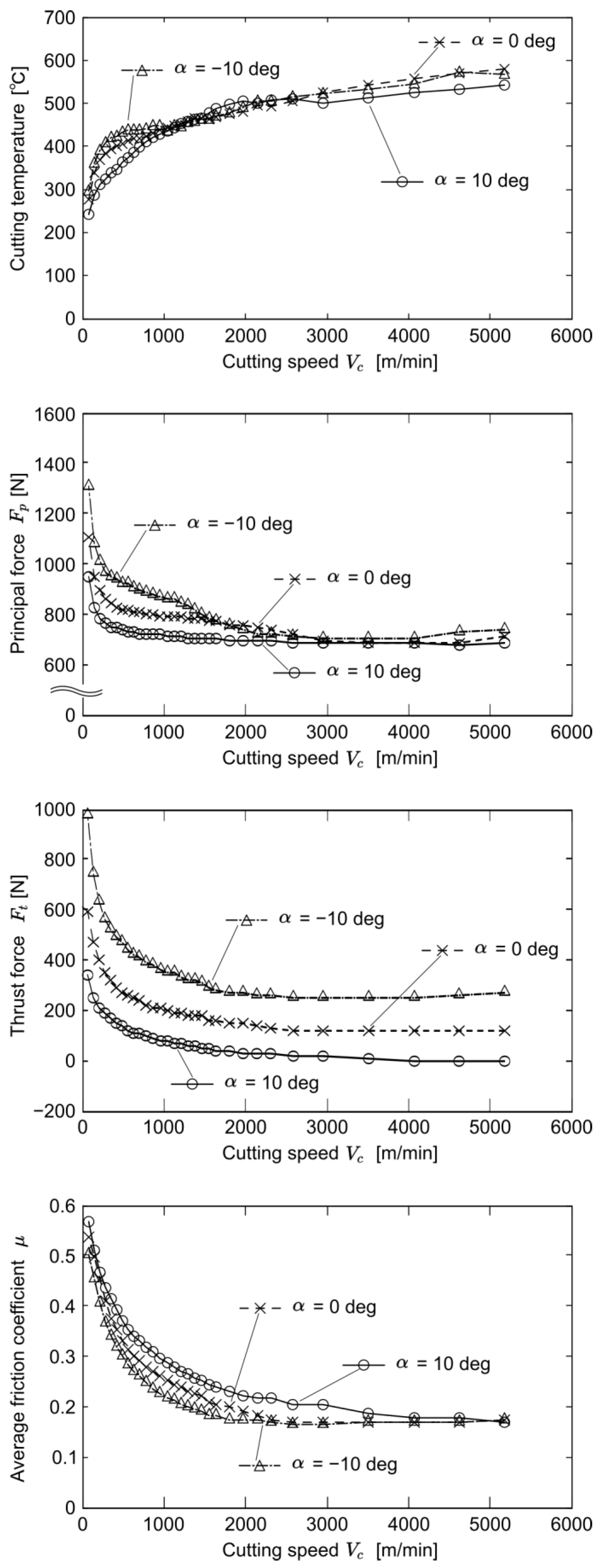
4.3. Effect of Rake Angle

Figure 13 shows the experimental results against the cutting speed and rake angle. In general, the machinability decreases as the rake angle decreases, i.e., the cutting edge becomes dull, and the cutting temperature increases. This trend can be observed from the measured cutting temperature and forces. Hence, the large friction coefficient drop in EHS cutting can be realized at a relatively lower cutting speed with a smaller rake angle. Specifically, EHS cutting can be realized around the cutting speed of V c = 1294 m/min with a rake angle of α = 0 deg and around the cutting speed of V c = 954 m/min with a rake angle of α = 10 deg. Note that the sticking zone in the vicinity of the cutting edge generally increases with a decrease in the rake angle, and the average friction coefficient at the tool–chip interface decreases [34]; this effect mixes with the temperature increase effect.

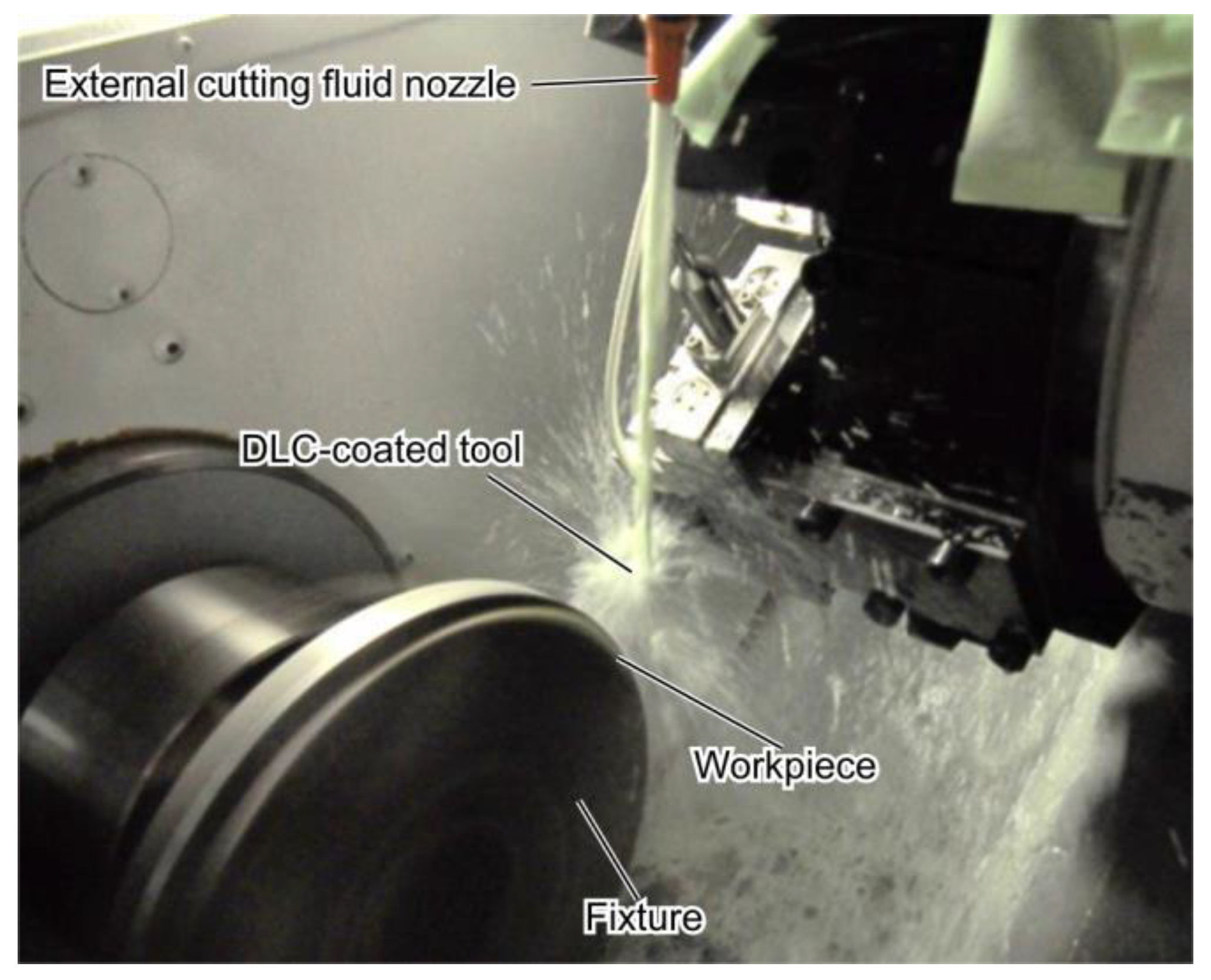
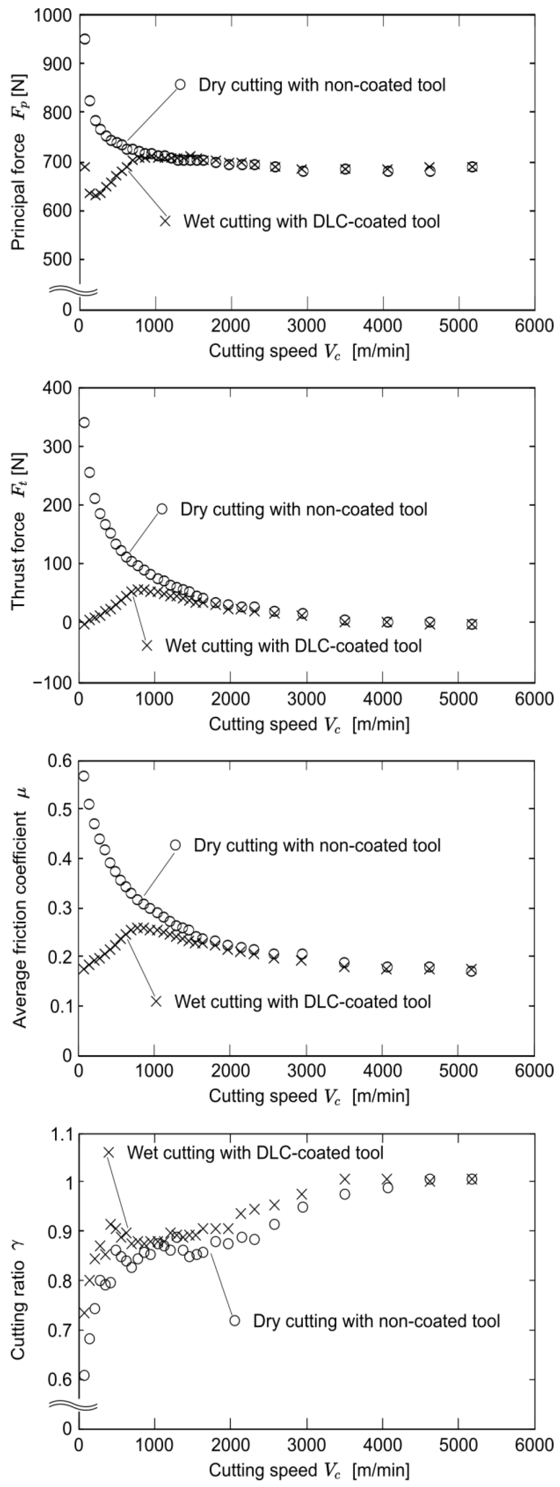
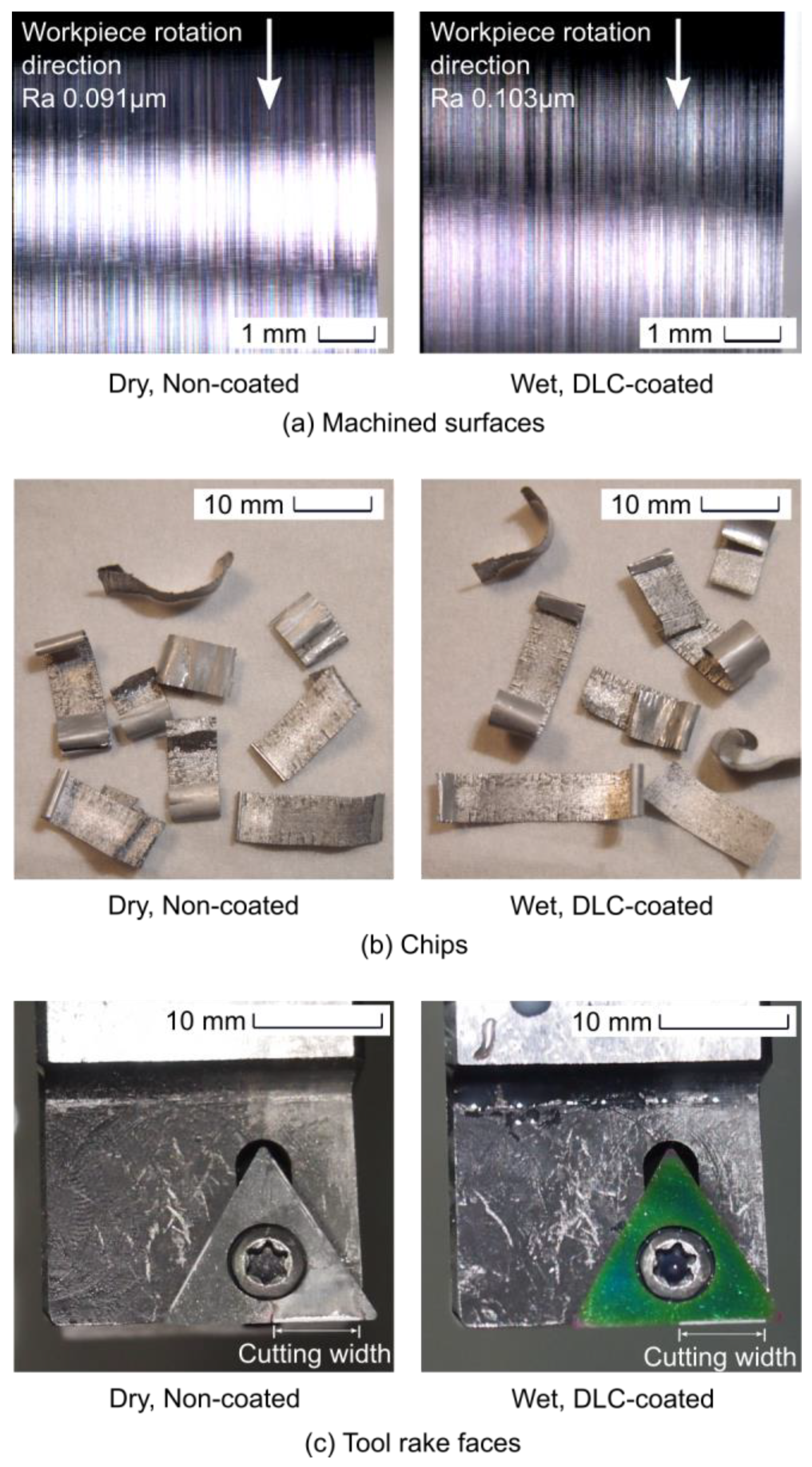
4.4. Comparison between Dry Cutting with Non-Coated Tool and Wet Cutting with Coated Tool

From the results shown in Figure 10, Figure 11, Figure 12 and Figure 13, it can be said that an extremely low friction coefficient can be achieved in the EHS cutting region. In this region, cutting fluid and coating, which reduce friction, should be unnecessary. Hence, friction/adhesion-less dry cutting with a non-coated tool can be realized by EHS cutting. To confirm this concept, dry cutting with a non-coated tool, i.e., the proposed application, and wet cutting with a DLC-coated tool, i.e., conventional cutting, are compared by experiments. Figure 14 shows the wet cutting process with external cutting fluid applied through a nozzle.
Figure 15 shows the cutting forces, average friction coefficient, and cutting ratio, where the cutting ratio is the ratio of the uncut chip thickness to the chip thickness. In the cutting-speed region of V c 2000 m/min, the thrust force and average friction coefficient in wet cutting with the DLC-coated tool are smaller than those in dry cutting with the non-coated tool, which means that the cutting fluid and coating are effective. In contrast, those in dry cutting with a non-coated tool are relatively large in this region since the workpiece tends to adhere to the rake face and cutting edge. Therefore, it can be said that the cutting fluid and coating are essential for the cutting of aluminum alloys by cemented carbide tools in this speed region. However, in the EHS cutting region of V c > 2000 m/min, there is almost no difference in the cutting forces and the average friction coefficient of the two situations, that is, the DLC coating and coolant have no effect in this region. This means that heat softening at the tool–chip interface in the EHS cutting of aluminum alloys can completely replace the coating and cutting fluid. Note that this fact can also be observed in the measured cutting ratio since the values are nearly the same in the EHS cutting region for both conditions.
Figure 16 shows the machined surfaces, disposed chips, and rake faces after cutting at a cutting speed of V c = 5184 m/min with/without cutting fluid and coating. The roughness of the machined surfaces is measured by a surface-measuring machine (FORMTRACER Avant S3000, Mitutoyo Corp., Kawasaki, Japan), and it is confirmed that both situations have nearly the same surface roughness. Both chips are short in length with almost no curl, and there is no difference between them. In addition, there is only a small difference in the rubbed mark left on the rake face, and no wear can be observed in either condition. In addition, there is no existence of a built-up edge on the cutting edges, which can also be assumed from the smooth rake-face side of the chips and the continuity of the lines in the cutting direction on the finished surfaces. Hence, these results show that friction and adhesion in dry cutting with a non-coated tool can be suppressed successfully by EHS cutting, and cutting fluid and coating can be eliminated for carbon-neutral manufacturing. This also means that the tool requirement level should become lower since coating is unnecessary. Note that chipping of the carbide tool during long-run cutting at high speeds may be a future task, as reported in the literature [35], though no chipping is observed at least in the experiments of the present paper.

5. Conclusions

Extraordinarily high-speed cutting mechanics were investigated in this research. Based on the investigated mechanics, dry cutting of aluminum alloys with non-coated carbide tools was proposed as an application. The investigated/achieved results are summarized as follows:
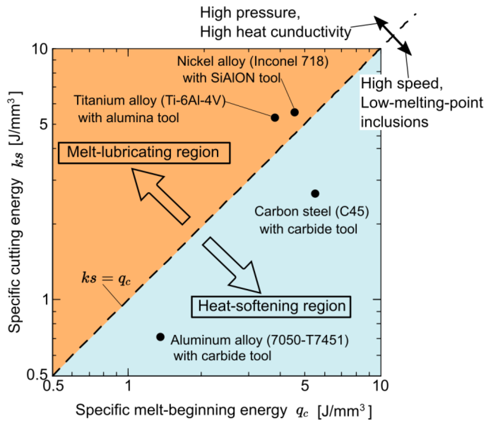
  • EHS cutting was categorized into two regions focusing on the specific cutting energy k s and specific melt-beginning energy q c : (1) melt-lubricating region ( k s > q c ) in which partial melting occurs and (2) heat-softening region ( k s < q c ) in which heat softening occurs. This research mainly focused on the latter region, and it was determined that a sufficiently high cutting temperature causes heat softening at the secondary plastic deformation zone rather than at the primary plastic deformation zone.
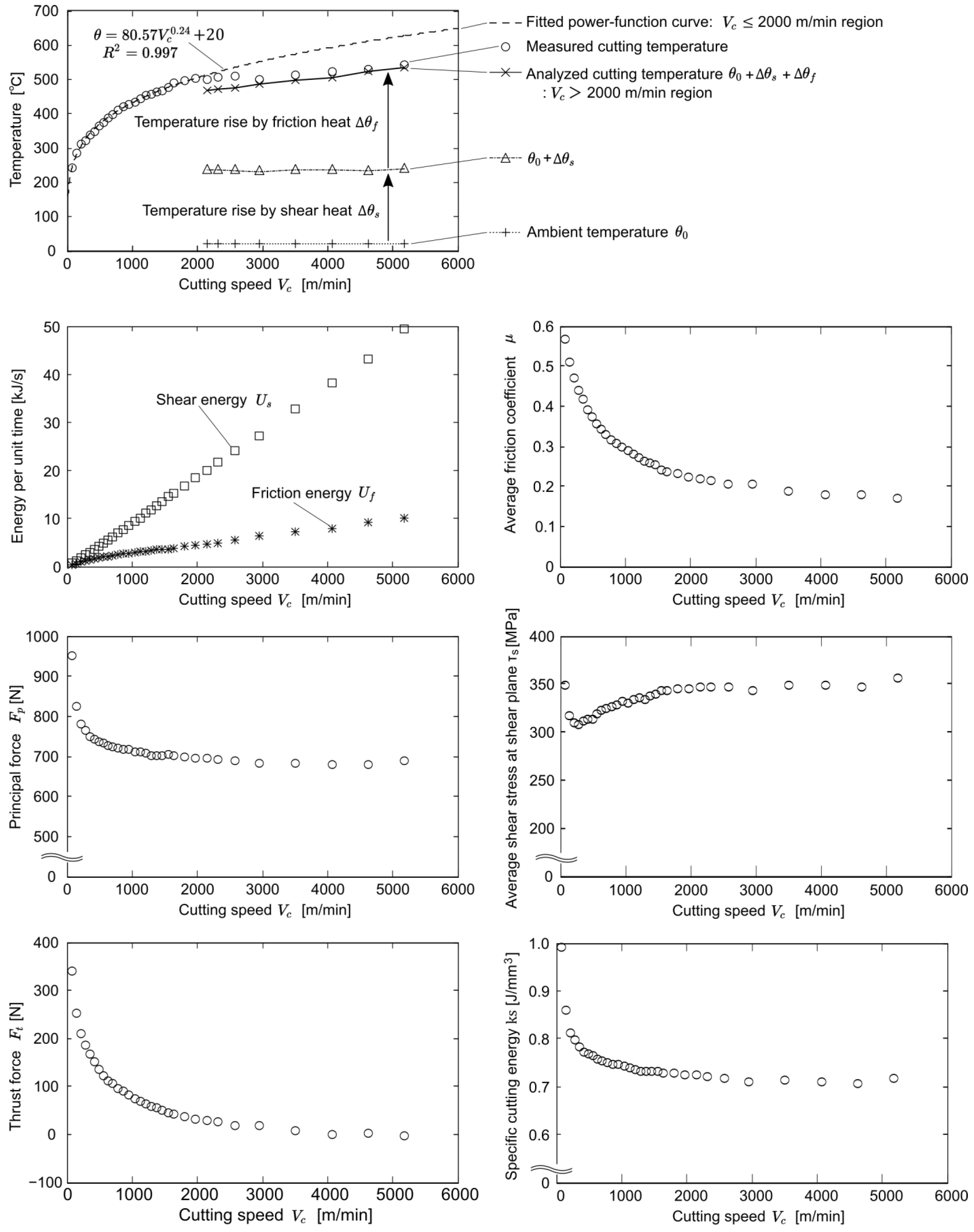
  • A simple analysis of the cutting temperature and experiments on soft and highly heat-conductive aluminum alloy were conducted to observe the mechanics. In the experiments, the cutting temperature and cutting forces were measured with varied cutting speed, feed per revolution, and rake angle. In the cutting-speed region of V c 2000 m/min, the cutting temperature showed a power function-like trend, and at the region of V c > 2000 , it changed to a gradually increasing trend.
  • The trend of gradual increase in cutting temperature agreed well with the analytical one based on Jaeger’s theory with assumptions that 100% of the shear and friction heat flow into the chip and that the chip thickness is large enough, and the increased friction speed and the intensifying heat/temperature gradient in the thickness direction of the chip were responsible for the gradual increase.
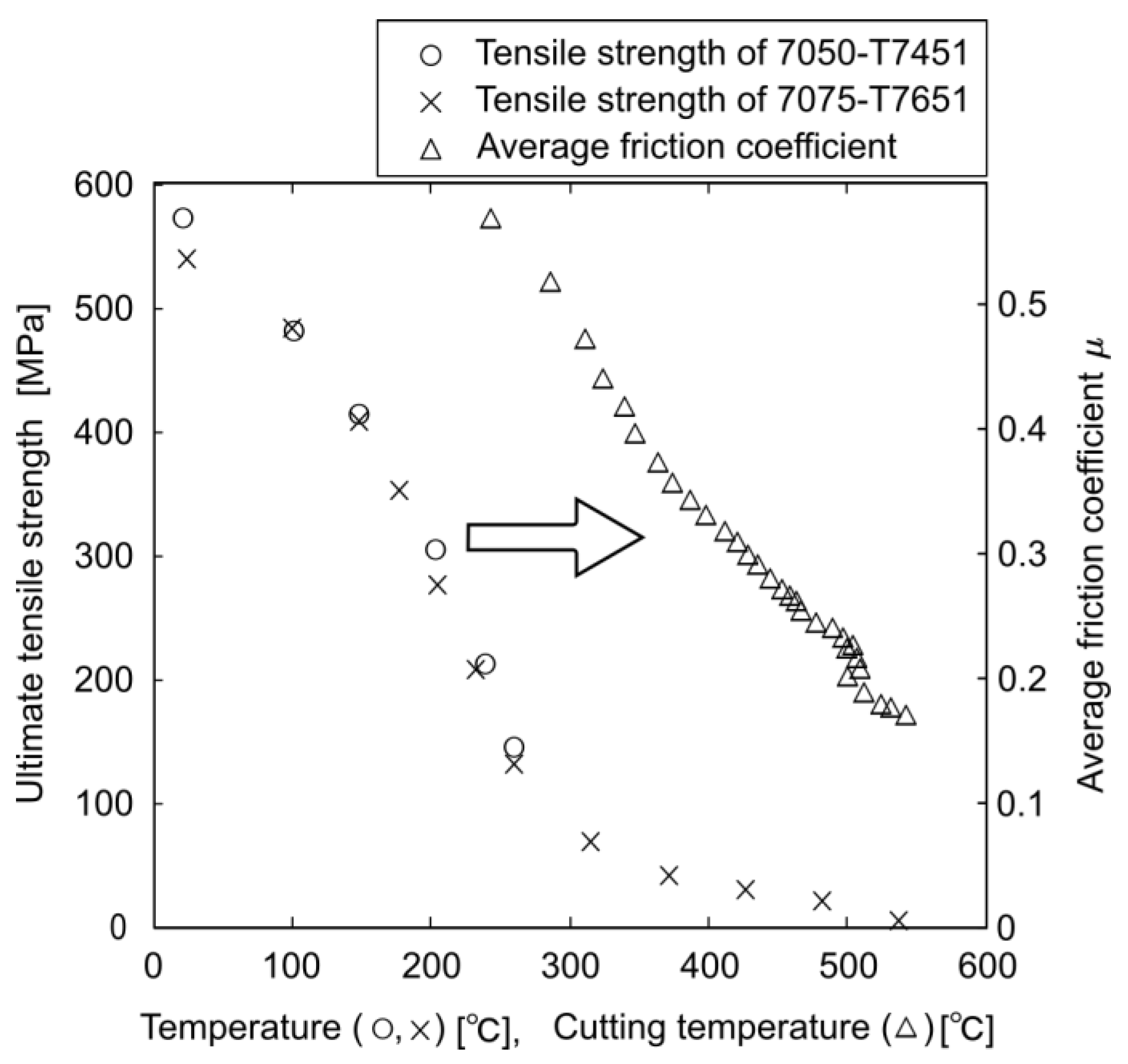
  • The average friction coefficient dropped from 0.569 at the lowest cutting speed to 0.170 in the EHS cutting region, whereas the average shear stress at the shear plane did not change much. Due to these facts, it was confirmed that heat softening in the tool–chip interface was responsible for the friction coefficient decrease. It was also shown that a larger feed per revolution and smaller rake angle increased the cutting temperature and reachability of EHS cutting.
  • Application to dry cutting of aluminum alloys with non-coated carbide tools was proposed, focusing on the low friction coefficient in EHS cutting. Experiments were conducted to compare dry cutting with a non-coated carbide tool and wet cutting with a DLC-coated carbide tool, and it was confirmed that the cutting fluid and coating had an effect in the relatively low-cutting-speed region of V c 2000 m/min. However, it was also shown that in the EHS cutting region of V c > 2000 m/min, there was almost no difference between the two conditions; the cutting fluid and coating could be eliminated. Although other advanced methods in the literature, e.g., high-pressure coolant systems and laser-assisted machining, can improve the cutting process, they require enormous additional energy compared to conventional wet cutting using coated tools. On the other hand, EHS cutting improves the cutting process greatly in an energy-friendly manner owing to the eliminated cutting fluid and coating. Hence, the proposed application can contribute to carbon-neutral manufacturing. Note that chipping of the carbide tool during long-run cutting in high speeds may be a future task as reported in the literature.
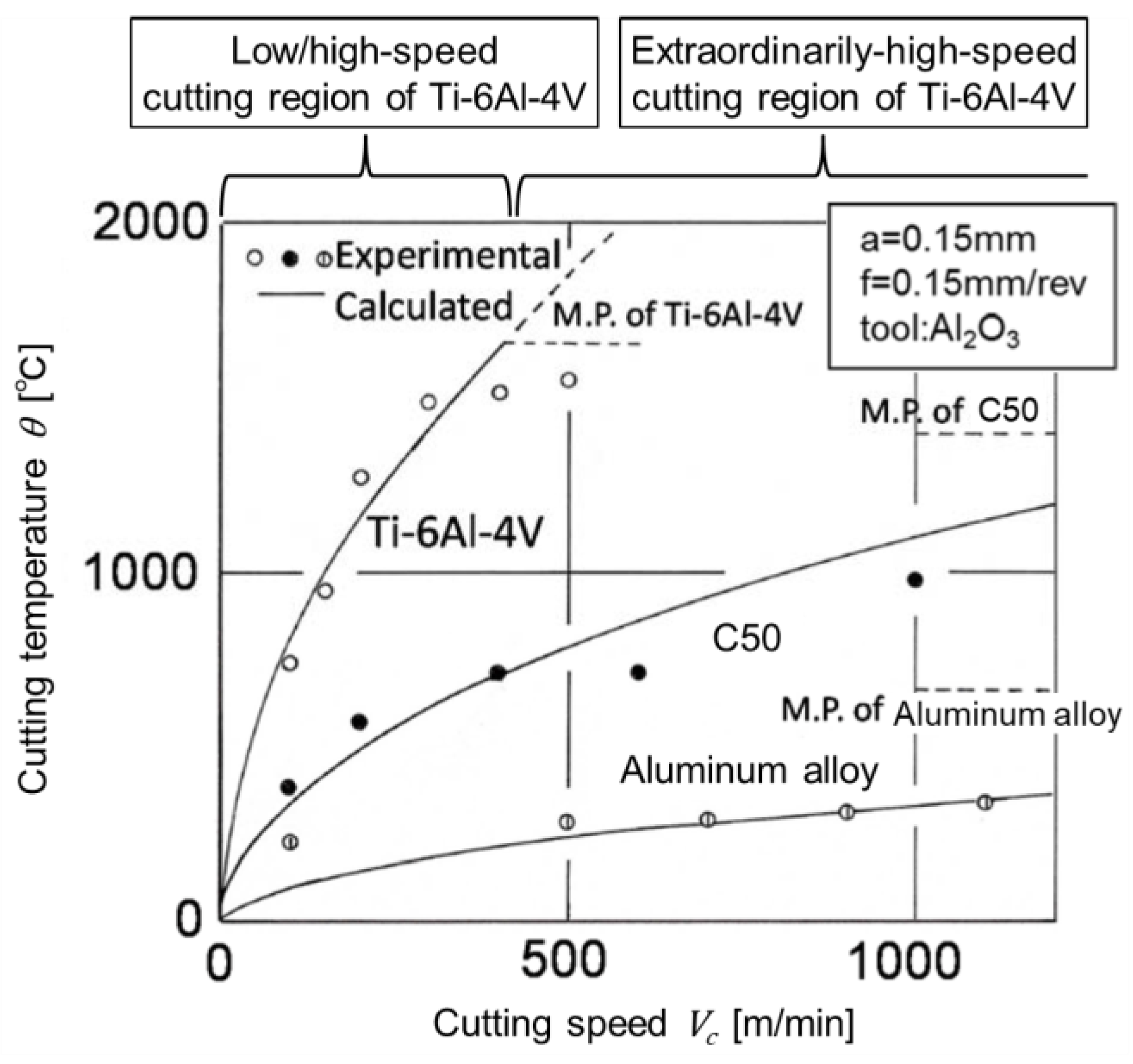
  • In this research, EHS cutting was applied to aluminum alloys. As for other soft and highly heat-conductive materials, e.g., copper alloy and magnesium alloy, EHS cutting should be able to be realized as it was for aluminum alloy. As for hard and lowly heat-conductive materials, e.g., titanium alloys and high-strength steels, the heat-softening points of these are usually large, e.g., around 600 °C for titanium alloy [36] and around 700 °C for (stainless) steel [37]. Although EHS cutting should be realized for these materials, tool wear may become a problem at such high temperatures. In those situations, utilizing highly heat-resistant tool materials such as ceramic and cBN may be one solution, where tool properties such as sharpness of the cutting edge and thermal conductivity should also be considered since they affect the reachability of EHS cutting.

Author Contributions

Conceptualization, E.S.; methodology, E.S.; software, J.E.; validation, T.H.; formal analysis, J.E.; investigation, J.E., T.H., E.S., and L.X.; resources, T.H.; data curation, J.E.; writing—original draft preparation, J.E. and T.H.; writing—review and editing, T.H., E.S., and L.X.; visualization, T.H.; supervision, T.H. and E.S.; project administration, T.H. and E.S.; funding acquisition, T.H. and E.S. All authors have read and agreed to the published version of the manuscript.

Funding

This research was partially supported by The Boeing Company and the “Knowledge Hub Aichi”, Priority Research Project (4th term) from Aichi Prefectural Government.

Data Availability Statement

The original contributions presented in the study are included in the article; further inquiries can be directed to the corresponding author.

Acknowledgments

The authors would like to express their sincere thanks to Mitsubishi Heavy Industries, Ltd. (Tokyo, Japan) for their help to conduct the present research.

Conflicts of Interest

Author Liangji Xu is employed by The Boeing Company. The authors declare that the research was conducted without any commercial or financial relationships that could be construed as a potential conflict of interest.

References

  1. Grzesik, W. Experimental investigation of the influence of adhesion on the frictional conditions in the cutting process. Tribol. Int. 1999, 32, 15–23. [Google Scholar] [CrossRef]
  2. Xia, Q.; Gillespie, D.R. Quasi-static finite element modelling of thermal distribution and heat partitioning for the multi-component system of high speed metal cutting. J. Mater. Process. Technol. 2020, 275, 116389. [Google Scholar] [CrossRef]
  3. Zemzemi, F.; Rech, J.; Salem, W.B.; Dogui, A.; Kapsa, P. Identification of a friction model at tool/chip/workpiece interfaces in dry machining of AISI4142 treated steels. J. Mater. Process. Technol. 2009, 209, 3978–3990. [Google Scholar] [CrossRef]
  4. Wang, B.; Liu, Z.; Song, Q.; Wan, Y.; Shi, Z. Proper selection of cutting parameters and cutting tool angle to lower the specific cutting energy during high speed machining of 7050-T7451 aluminum alloy. J. Clean. Prod. 2016, 129, 292–304. [Google Scholar] [CrossRef]
  5. Santos, M.C.; Machado, A.R.; Sales, W.F.; Barrozo, M.A.; Ezugwu, E.O. Machining of aluminum alloys: A review. Int. J. Adv. Manuf. Technol. 2016, 86, 3067–3080. [Google Scholar] [CrossRef]
  6. Abele, E.; Sielaff, T.; Schiffler, A.; Rothenbücher, S. Analyzing energy consumption of machine tool spindle units and identification of potential for improvements of efficiency. In Glocalized Solutions for Sustainability in Manufacturing: Proceedings of the 18th CIRP International Conference on Life Cycle Engineering, Technische Universität Braunschweig, Braunschweig, Germany, 2–4 May 2011; Springer: Berlin/Heidelberg, Germany, 2011; pp. 280–285. [Google Scholar]
  7. Gontarz, A.; Züst, S.; Weiss, L.; Wegener, K. Energetic machine tool modeling approach for energy consumption prediction. In Proceedings of the GCSM 2012 10th Global Conference on Sustainable Manufacturing, Istanbul, Turkey, 31 October–2 November 2012; Institute of Machine Tools and Manufacturing (IWF), Swiss Federal Institute of Technology: Zürich, Switzerland, 2012. [Google Scholar] [CrossRef]
  8. Kouam, J.; Songmene, V.; Balazinski, M.; Hendrick, P. Effects of minimum quantity lubricating (MQL) conditions on machining of 7075-T6 aluminum alloy. Int. J. Adv. Manuf. Technol. 2015, 79, 1325–1334. [Google Scholar] [CrossRef]
  9. Denkena, B.; Dittrich, M.A.; Jacob, S. Energy efficiency in machining of aircraft components. Procedia CIRP 2016, 48, 479–482. [Google Scholar] [CrossRef]
  10. Naves, V.T.G.; Da Silva, M.B.; Da Silva, F.J. Evaluation of the effect of application of cutting fluid at high pressure on tool wear during turning operation of AISI 316 austenitic stainless steel. Wear 2013, 302, 1201–1208. [Google Scholar] [CrossRef]
  11. Anderson, M.; Patwa, R.; Shin, Y.C. Laser-assisted machining of Inconel 718 with an economic analysis. Int. J. Mach. Tools Manuf. 2006, 46, 1879–1891. [Google Scholar] [CrossRef]
  12. Sutter, G.; Molinari, A. Analysis of the cutting force components and friction in high speed machining. J. Manuf. Sci. Eng. 2005, 127, 245–250. [Google Scholar] [CrossRef]
  13. Philippon, S.; Sutter, G.; Molinari, A. An experimental study of friction at high sliding velocities. Wear 2004, 257, 777–784. [Google Scholar] [CrossRef]
  14. Ozlu, E.; Budak, E.; Molinari, A. Analytical and experimental investigation of rake contact and friction behavior in metal cutting. Int. J. Mach. Tools Manuf. 2009, 49, 865–875. [Google Scholar] [CrossRef]
  15. Recht, R.F. A Dynamic Analysis of High Speed, Machining. ASME J. Eng. Ind. 1985, 107, 309–315. [Google Scholar] [CrossRef]
  16. Wang, B.; Liu, Z.; Cai, Y.; Luo, X.; Ma, H.; Song, Q.; Xiong, Z. Advancements in material removal mechanism and surface integrity of high speed metal cutting: A review. Int. J. Mach. Tools Manuf. 2021, 166, 103744. [Google Scholar] [CrossRef]
  17. Ueda, T.; Hirai, Y.; Shamoto, E. Experimental studies on cutting temperature and its effect in high speed turning of difficult-to-cut materials with ceramic tool. Trans. JSME 2017, 83, 17-00344. (In Japanese) [Google Scholar] [CrossRef]
  18. Richardson, D.J.; Keavey, M.A.; Dailami, F. Modelling of cutting induced workpiece temperatures for dry milling. Int. J. Mach. Tools Manuf. 2006, 46, 1139–1145. [Google Scholar] [CrossRef]
  19. Ueda, T.; Hirai, Y.; Uto, S.; Shamoto, E. Studies on cutting temperature by dimensional analysis (Influence of cutting conditions in turning with Al2O3 cutting tool). Trans. JSME 2019, 85, 18-00284. (In Japanese) [Google Scholar] [CrossRef]
  20. Ueda, T.; Sato, M.; Nakayama, K. The temperature of a single crystal diamond tool in turning. CIRP Ann. 1998, 47, 41–44. [Google Scholar] [CrossRef]
  21. Ueda, T.; Uto, S.; Hirai, Y.; Shamoto, E. Studies on cutting temperature by dimensional analysis (2nd report: Influence of thermal properties of workpiece and tool materials). Trans. JSME 2020, 86, 20-00100. (In Japanese) [Google Scholar] [CrossRef]
  22. Hayasaka, T.; Jung, H.; Azuma, K.; Shamoto, E. Consolidated chatter stability prediction model considering material removing and ploughing processes. Precis. Eng. 2019, 59, 120–133. [Google Scholar] [CrossRef]
  23. Suzuki, N.; Enmei, R.; Hashimoto, Y.; Shamoto, E.; Hatano, Y. Tool failure mechanism in high-speed milling of Inconel 718 by use of ceramic tools. Int. J. Autom. Technol. 2014, 8, 837–846. [Google Scholar] [CrossRef]
  24. Minamino, Y.; Yamane, T.; Miyake, T.; Koizumi, M.; Miyamoto, Y. Effect of high pressure on diffusion reactions and phase diagram in Al–Mg system. Mater. Sci. Technol. 1986, 2, 777–783. [Google Scholar] [CrossRef]
  25. Deel, O.L.; Ruff, P.E.; Mindlin, H. Engineering Data on New Aerospace Structural Materials; AFML-TR-73-114; Battelle’s Columbus Laboratories: Columbus, OH, USA, 1973. [Google Scholar]
  26. Kaufman, J.G. (Ed.) Properties of Aluminum Alloys: Tensile, Creep, and Fatigue at High and Low Temperatures; ASM International: Almere, The Netherlands, 1999; pp. 206–217. [Google Scholar]
  27. Subroto, T.; Miroux, A.G.; Eskin, D.G.; Katgerman, L. Tensile mechanical properties, constitutive parameters and fracture characteristics of an as-cast AA7050 alloy in the near-solidus temperature regime. Mater. Sci. Eng. A 2017, 679, 28–35. [Google Scholar] [CrossRef]
  28. Battelle Memorial Institute; William J. Hughes Technical Center (U.S.). Metallic Materials Properties Development and Standardization—MMPDS-14; Federal Aviation Administration: Washington, DC, USA, 2019.
  29. Aluminum Standards and Data Metric SI; The Aluminum Association: Arlington, VA, USA, 2017; Available online: https://www.aluminum.org/aluminum-standards-and-data (accessed on 11 August 2024).
  30. Chao, B.T.; Trigger, K.J. The Significance of the Thermal Number in Metal Machining. Trans. ASME 1953, 75, 109–115. [Google Scholar] [CrossRef]
  31. Jaeger, J.C. Moving sources of heat and the temperature of sliding contacts. Proc. R. Soc. New South Wales 1942, 76, 203–224. [Google Scholar] [CrossRef]
  32. Loewen, E.G.; Shaw, M.C. On the analysis of cutting-tool temperatures. Trans. ASME 1954, 76, 217–225. [Google Scholar] [CrossRef]
  33. Herbert, E.G. The Measurement of Cutting Temperatures. Proc. Inst. Mech. Eng. 1926, 110, 289–329. [Google Scholar] [CrossRef]
  34. Kato, S.; Yamaguchi, K.; Yamada, M. Stress Distribution at the Interface Between Tool and Chip in Machining. ASME J. Eng. Ind. 1972, 94, 683–689. [Google Scholar] [CrossRef]
  35. Calatoru, V.D.; Balazinski, M.; Mayer, J.R.R.; Paris, H.; L’Esperance, G. Diffusion wear mechanism during high-speed machining of 7475-T7351 aluminum alloy with carbide end mills. Wear 2008, 265, 1793–1800. [Google Scholar] [CrossRef]
  36. Boyer, R.; Welsch, G.; Collings, E.W. Materials Properties Handbook: Titanium Alloys; ASM International: Almere, The Netherlands, 1994; Volume 76. [Google Scholar]
  37. Chen, J.; Young, B. Stress-strain curves for stainless steel at elevated temperatures. Eng. Struct. 2006, 28, 229–239. [Google Scholar] [CrossRef]
Figure 1. Schematic of cutting process and cutting temperature distribution [2].
Jmmp 08 00198 g001
Figure 2. Influence of cutting speed on cutting temperature in dry cutting with Al2O3 ceramic tool [19].
Jmmp 08 00198 g002
Figure 3. Relation between specific cutting energy k s and specific melt-beginning energy q c .
Jmmp 08 00198 g003
Figure 4. Tensile property of aluminum alloys against temperature [25,26].
Jmmp 08 00198 g004
Figure 5. Schematic illustration of calibration system of thermoelectromotive force.
Jmmp 08 00198 g005
Figure 6. Result of TEMF calibration curve between 7050-T7451 alloy and cemented carbide.
Jmmp 08 00198 g006
Figure 7. Photographs of experimental setup for milling-like turning experiments.
Jmmp 08 00198 g007
Figure 8. Schematic of experimental setup.
Jmmp 08 00198 g008
Figure 9. Example of thermoelectromotive force and cutting forces in one spindle revolution at cutting speed Vc = 5184 m/min, feed per revolution f = 0.15 mm/rev, and dry cutting with non-coated carbide tool.
Jmmp 08 00198 g009
Figure 10. Effects of cutting speed V c on temperatures, cutting forces, average friction coefficient, average shear stress at shear plane, and specific cutting energy at feed per revolution f = 0.15 mm/rev, dry environment, and non-coated tool.
Jmmp 08 00198 g010
Figure 11. Comparison of ultimate tensile strength against temperature and average friction coefficient μ against cutting temperature in dry environment and with non-coated tool.
Jmmp 08 00198 g011
Figure 12. Effects of feed per revolution f on cutting temperature and cutting forces at cutting speed V c = 1465 m/min, dry environment, and non-coated tool.
Jmmp 08 00198 g012
Figure 13. Effects of rake angle α and cutting speed V c on cutting temperature, cutting forces, and average friction coefficient at feed per revolution f = 0.15 mm/rev, dry environment, non-coated tool.
Jmmp 08 00198 g013
Figure 14. Photograph of conventional cutting process with external cutting fluid.
Jmmp 08 00198 g014
Figure 15. Comparison of cutting forces, average friction coefficient, and cutting ratio between dry cutting with non-coated tool and wet cutting with DLC-coated tool.
Jmmp 08 00198 g015
Figure 16. Photographs of (a) machined surfaces, (b) chips, and (c) rake faces after cutting at cutting speed V c = 5184 m/min.
Jmmp 08 00198 g016
Table 1. Parameters used for prediction of cutting temperature [28,29].
Cutting conditionsFeed per revolution f [mm/rev]0.15
Cutting width b [mm]6.4
Identified parameterSpecific cutting force in principal direction K p [MPa]713.54
Properties of 7050-T7451Density ρ [g/cc]2.823
Specific heat capacity c [J/(kg∙°C)]962.964
Thermal conductivity λ [W/(m∙°C)]157.497
Thermal diffusivity K = λ / ρ c [mm2/s]57.936
Melting (solidus) temperature θ m [°C]490
Table 2. Details of fixtures.
Fixture TypeLargeSmall
Fixture diameter [mm]290 160
Fixture mass [kg]13.26 4.41
Cutting speed range [m/min]>1500<1500
Workpiece diameter range [mm]354 to 292255 to 162
Cutting angle range (one end) [deg]26.1 to 31.836.6 to 59.2
Table 3. Details of tools.
Tool TypeT1T2T3T4
Rake angle [deg]100−1010
Clearance angle [deg]17171717
CoatingNon-coatedDLC
Cutting edge radius [µm]Approximately 5Approximately 6
Rake surfaceLapped ( R z   0.03   μ m ) Lapped and
then coated
Table 4. Experimental conditions.
Experiment TypeTool TypesFixture TypesFixed ConditionsVaried Conditions
Cutting speedT1Large, SmallDry cutting
Feed per revolution f : 0.15 mm/rev
Rake angle α : +10 deg
Cutting speed V c : 70 to 5184 m/min
Feed per revolutionT1SmallDry cutting
Cutting speed V c : 1465 m/min
Rake angle α : +10 deg
Feed per revolution f : 0.005 to 0.2 mm/rev
Rake angleT1, T2, T3Large, SmallDry cutting
Feed per revolution f : 0.15 mm/rev
Cutting speed V c : 70 to 5184 m/min
Rake angle α : +10, 0, −10 deg
Cutting fluid and coatingT1, T4Large, SmallFeed per revolution f : 0.15 mm/rev
Rake angle α : +10 deg
Cutting speed V c : 70 to 5184 m/min
Cutting fluid: dry, wet
Tool coating: non-coated, DLC-coated
Disclaimer/Publisher’s Note: The statements, opinions and data contained in all publications are solely those of the individual author(s) and contributor(s) and not of MDPI and/or the editor(s). MDPI and/or the editor(s) disclaim responsibility for any injury to people or property resulting from any ideas, methods, instructions or products referred to in the content.

