Abstract
Additive manufacturing (AM) methods have been gaining momentum because they provide vast design and fabrication possibilities, increasing the accessibility of state-of-the-art hardware through recent developments in user-friendly computer-aided drawing/engineering/manufacturing (CAD/CAE/CAM) tools. However, in comparison to the conventional manufacturing methods, AM processes have some disadvantages, including the machining precision and fabrication process times. The first issue has been mostly resolved through the recent advances in manufacturing hardware, sensors, and controller systems. However, the latter has been widely investigated by researchers with different toolpath planning perspectives. As a contribution to these investigations, the present study proposes a toolpath planning method for AM, which aims to provide highly continuous yet distance-optimized solutions. The approach is based on the utilization of the signed distance field (SDF), clustering, and minimization of toolpath distances among cluster centroids. The method was tested on various geometries with simple closed curves to complex geometries with holes, which provides effective toolpaths, e.g., with relative distance reduction percentages up to 16.5% in comparison to conventional rectilinear infill patterns.
1. Introduction
Additive manufacturing (AM) forms objects by fusing or bonding materials primarily including metals, polymers, ceramics, and composites [1,2,3,4]. AM provides flexibility in product design and effective solutions for complex geometry fabrication, leading to on-demand production, reduced material and energy consumption during fabrication, and custom automation solutions, to name a few [5,6]. Therefore, AM has recently undergone tremendous progress in the biomedical, construction, automotive, defense, and aerospace industries [7,8,9]. Over the last decades, the products fabricated with AM technologies reached an annual growth rate of approximately 26% [10]. For instance, various AM methods, e.g., fused filament fabrication (FFF) and directed energy deposition (DED), gain ever-increasing attention due to their corresponding printing systems becoming less-expensive and easier-to-use. In addition to these, novel systems with lower maintenance costs and energy efficiency, as well as a wide range of cost-effective materials such as polymers, metals, and ceramics, also make them favorable manufacturing solutions [11]. However, as seen in many different AM methods, the manufactured products contain defects due to machining precision and fabrication process times. The recent advances in the manufacturing hardware, sensors, vibration compensation, and controller systems have a great impact on the resolution for machine precision-related issues [12,13,14,15]. Nonetheless, process time optimization has been widely investigated by researchers with different toolpath planning perspectives and bypassing methods [16]. In principle, toolpaths are generated by transforming STL (stereolithography)-based computer aided drawing (CAD) files into layers, and filling these layers with lines or curves based on selected infill patterns [17]. Traditionally, the slicer software produces successive layers with infill patterns, which are commonly based on rectilinear geometries with angular variations, also known as zig-zag infill patterns [18,19,20]. In addition to the rectilinear geometries, various patterns including grids, honeycombs, triangles, and gyroids have also been investigated in the literature [10,21,22]. However, the continuity of material deposition, which plays an important role for the structural integrity and manufacturing process time, is rather challenging with the conventional infill patterns and toolpath generation perspectives [23,24]. Hence, in recent years, Jin et al. and Habib et al. developed toolpath planning algorithms, which use contours for the sliced layer boundaries and continuous infill patterns for the interior regions [25,26]. Moreover, Bui et al. and Liu et al. also proposed planning strategies with collision detection and resolution algorithms, which aim at optimizing the nozzle movements while achieving desired manufacturing quality [5,27]. In addition to these novel studies, Rauch et al. and Evjemo et al. proposed multi-axis toolpath generation algorithms for manufacturing metallic thin-walled structures to be used with DED methods [28,29].
As a contribution to the novel studies in the field of toolpath generation and optimization, the current study presents a framework by means of signed distance field (SDF) and cluster-based methods using distance optimization algorithms. The study is organized as follows. Section 2 (Materials and Methods) provides an overview of SDF, clusters, and the present framework for toolpath planning while Section 3 (Results and Discussions) provides the results and comparison of distances obtained by the current and conventional toolpath generation methods. Closing remarks, limitations, and future plans are provided in Section 4 (Conclusions).
2. Materials and Methods
The working principles of the present method comprise (I) slicing of a three-dimensional (3-D) geometry based on the selected z-axis resolution; (II) generation of SDF for each slice; (III) SDF partitioning for defining clusters of proximate position data sets and toolpath optimization based on the clusters; and (IV) machine-instruction (G-Code) generation based on the optimized toolpaths for AM, which is an optional step and briefly explained in Appendix A. The workflow is schematized in Figure 1. The entire workflow was executed with in-house codes written in Mathematica 13.0 technical computing software [30], which can be found in a Github repository [31].
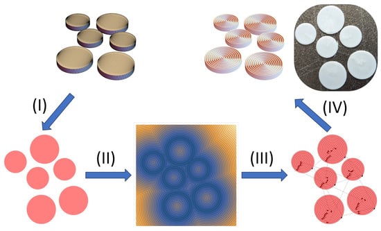
Figure 1.
Workflow: (I) Three-dimensional (3-D) geometry slicing and two-dimensional (2-D) projection, (II) generation of signed distance fields, (III) clustering and distance minimization for optimal toolpaths, (IV) generation of G-Code and additive manufacturing by means of the computed toolpaths.
In the present study, two options can be used to define the domain, which comprise geometries generated with implicit functions by using ImplicitRegion[] and RegionPlot3D[] functions readily available in Mathematica, and geometries imported in a STL file format. Since the STL files are widely used for industrial and academic purposes, the focus here is kept on the latter option. Hence, the imported geometries are sliced with DiscretizeRegion[], a default Mathematica function, along the z-axis and a user-defined thickness value, e.g., between 0.1 mm and 0.2 mm, which are commonly used in the FFF method. As illustrated in the first step in Figure 1, the generated thin yet 3-D slices are then projected as 2-D polygons by means of the RegionPlot[] function. The polygon bounds are used to determine the reference contours (or isolines) comprising points with the assigned distance value of zero, . As illustrated in Figure 2, the signed distance function for any point q is calculated with respect to . To elaborate,
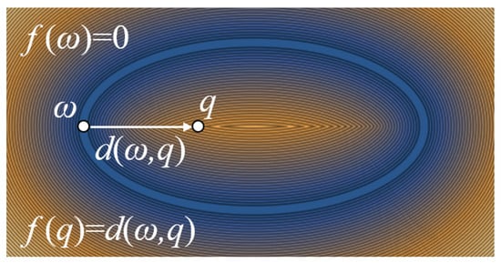
Figure 2.
Signed distance field calculations for a hollow ellipse.
As depicted in the second step in Figure 1, connecting points with equal distance values to the closest polygon bounds results in the generation of continuous isolines, i.e., forming the SDF [32,33,34]. To refine the SDF, the enclosed isolines within the polygon bounds are processed. Thereafter, the remaining isolines can be used to generate toolpaths for AM purposes. However, for complex geometries, toolpaths generated by means of this strategy may end up with long process times, which is mainly due to high-probability of non-productive nozzle movements. Therefore, distance-based optimization among the generated isolines can reduce such nozzle movements. In order to execute the optimization, isolines are first partitioned into smaller point sets by means of clustering algorithms, which is a powerful approach for determining patterns with a certain degree of similarity [35]. The generated clusters represent the proximate sets of points based on distance. For the clustering, Mathematica’s built-in FindClusters[] function is used with three different methods, namely, ’NeighborhoodContraction’, ’Agglomerate’, and ’DBSCAN’ (density-based spatial clustering of applications with noise). These methods have been successfully implemented to classify and cluster large data sets in financial problems, vehicle motion trajectories, and positioning and tracking problems in the fields of transportation and urbanization, to name a few [36,37]. The ’NeighborhoodContraction’ method is a neighbor-based clustering method, which is suitable for arbitrary cluster shapes and sizes [38]. It constructs clusters by using neighborhoods based on distance, geometry, and density [39]. The ’Agglomerate’ method, on the other hand, partitions data by using an agglomerative clustering approach, which is suitable for clusters of similar densities but may fail with clusters of varying sizes [40]. It is a hierarchical method, i.e., sub-clusters are successively merged based on their distance measures to form the clusters [41,42]. In addition to these methods, the ’DBSCAN’ method is also one of the commonly used clustering algorithms, which groups set of points that are packed closely. It is an efficient way of clustering large spatial data, which is based on distance and density metrics [43]. In this method, a sufficient number of points form a cluster, and the process of clustering continues until all the density-connected clusters are detected [44].
As shown in the third step of Figure 1, the clustering process is followed by toolpath optimization between the clusters. For this purpose, cluster centroids are first computed by averaging the coordinates of the point sets in each cluster. Thereafter, the distance traveled by the nozzle between the clusters is determined based on the total distance minimization. This can be achieved by constructing a cost matrix based on a distance metric between each cluster centroid d(m, n), for which m and n refer to centroid positions, such that [5,17]
The optimal permutation(s) can be then obtained through the minimization of the total distances [45] so that
3. Results and Discussion
In order to compare the proposed method with the conventional toolpath generation strategies, various sample geometries with and without holes regardless of their convex or concave boundaries, which comprise ’Stanford Bunny’, ’Square with Holes’, ’Helical Gear’, and ’Polygons with Holes’, were investigated and are depicted in Figure 3. For comparison purposes, a conventional in-house rectilinear toolpath code with an alternating angle combination of a and variation is used, which is readily available in a Github repository [31]. For both methods, z- and xy-resolutions are 0.2 mm while the infill density is set to be 100%. The comparison metric is taken as the absolute value of the relative toolpath distance reduction percentage so that
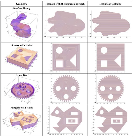
Figure 3.
Tested samples and generated toolpaths for selected sections by means of the current SDF−based and conventional rectilinear methods. The in−plane resolution was chosen to be 0.2 mm.
The comparative study in Figure 4 demonstrates that REL(%) values for the depicted layer of ’Stanford Bunny’ are 2.9%, 3.5%, and 2.8% for three different clustering options, ’NeighborhoodContraction’, ’Agglomerate’, and ’DBSCAN’, respectively. This shows that for the geometries without hole(s), the conventional rectilinear toolpaths can be an effective solution. On the other hand, for more complex layers with the holes, the present method produces results with shorter toolpaths compared to the conventional rectilinear toolpath planning. For the investigated layer of ’Square with Holes’, REL(%) values of 7.3%, 7.4%, and 6.2% are obtained with the ’NeighborhoodContraction’, ’Agglomerate’, and ’DBSCAN’ clustering options, respectively. Meanwhile, REL(%) values of 11.2%, 16.5%, and 15.1% for the tested layer of ’Polygons with Holes’ are obtained by means of the aforementioned clustering options. Interestingly, there is a variation of REL(%) for the ’Helical Gear’ sample. Although the ’Agglomerate’ clustering option provides a shorter toolpath than the conventional method with a REL(%) value of 1.3%, both ’NeighborhoodContraction’ and ’DBSCAN’ produce longer toolpaths with REL(%) values of 5.1% and 7.5%. This is presumably due to the position data sets being intertwined especially at the gear teeth regions, which can cause inaccurate clustering.
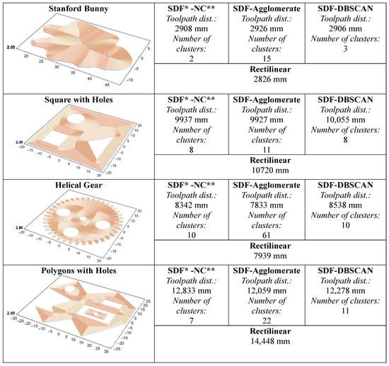
Figure 4.
Generated toolpaths and number of clusters for various geometries by means of the current SDF−based and conventional rectilinear methods. The in−plane resolution was chosen to be 0.2 mm. SDF* and NC** refer to signed distance field and NC** refers to neighborhood contraction, respectively.
4. Conclusions
The present study focuses on a framework generating optimal toolpaths based on SDF and clustering algorithms. Although it is possible to utilize direct implicit functions as geometric regions in Mathematica, here, STL files are used as input geometry files. The reason for this choice is due to STL files being one of the common CAD formats used in the additive manufacturing industries.
The current investigations demonstrate that for complex geometries, e.g., with holes, the present approach is an effective way of generating toolpaths, which reduces non-productive nozzle movements. Hence, process times, material, and energy consumption during fabrication are reduced with such toolpath optimization strategies, which results in sustainable process and material utilization solutions [46,47]. Particularly, the ’Agglomerate’ clustering algorithm is deduced to provide toolpaths with feasible distances. To illustrate, for the investigated slice of the ’Polygons with Holes’ sample, a relative distance reduction of up to 16.5% is achieved with the ’Agglomerate’ clustering algorithm in comparison with the toolpath generated by means of the conventional rectilinear toolpath planning method. Nevertheless, for closed geometries without holes, both the rectilinear and present approaches produce toolpaths of comparable distances, i.e., a relative distance percentage of 3.5% for the tested slice for ’Stanford Bunny’.
Even though the present method has merits, there are also various limitations inherited from the input geometry files. For instance, the resolution and discrepancies of the geometry have direct effects on the final product surface quality; therefore, pre-processing, which comprises contour smoothing and noise reductions, plays a critical role. Currently, the default Mathematica mesh conversion and smoothing functions are used to address these issues. However, these functions can be further investigated to improve the geometric accuracy and meet the dimensional standards for the final fabricated product. These limitations also create a room for improvement and lead to new research opportunities. For example, scalability studies for large and complex geometries, as well as optimization assessments for the emerging areas of four- or five-axis manufacturing systems, are some examples for such investigations to specify toolpath generation constraints and practical limits. Furthermore, the development of collision-avoidance and support structure algorithms and rigorous characterizations of part quality and structural integrity are other important topics, which are planned to be investigated in detail as part of future work. In addition to these, due to the current framework being based on clustering algorithms, high-performance, and real-time computation strategies based on machine learning algorithms, the integration of multi-nozzle systems and their AM implementations over clusters will be also evaluated in upcoming research studies.
Funding
This research received no external funding.
Data Availability Statement
Codes and data supporting the reported results can be found in a Github repository (https://github.com/metudust/Toolpath_and_GCode_Generator) (accessed on 10 September 2024).
Conflicts of Interest
The author declares no conflicts of interest.
Appendix A
A G-Code generator written in Mathematica technical computing software is also provided in the Github repository [31]. The extrusion rate in the code is expressed as
which can be successfully tuned and used for FFF 3D printing. Here, w, h, L, M, D refer to the extrusion width, layer height, travel length, multiplier ( ∼0.065 for the current toolpath generator and printer in use), and nozzle diameter, respectively. Formulation details and parameter definitions can be found in [24]. A brief explanation of the G-Code command lines is depicted in Figure A1.

Figure A1.
Schematic representation of the nozzle movement and material extrusion based on the G-Code commands.
References
- Wong, K.V.; Hernandez, A. A review of additive manufacturing. Int. Sch. Res. Not. 2012, 2012, 208760. [Google Scholar] [CrossRef]
- Huang, S.H.; Liu, P.; Mokasdar, A.; Hou, L. Additive manufacturing and its societal impact: A literature review. Int. J. Adv. Manuf. Technol. 2013, 67, 1191–1203. [Google Scholar] [CrossRef]
- Keleş, Ö.; Blevins, C.W.; Bowman, K.J. Effect of build orientation on the mechanical reliability of 3D printed ABS. Rapid Prototyp. J. 2017, 23, 320–328. [Google Scholar] [CrossRef]
- Rafiee, M.; Abidnejad, R.; Ranta, A.; Ojha, K.; Karakoç, A.; Paltakari, J. Exploring the possibilities of FDM filaments comprising natural fiber-reinforced biocomposites for additive manufacturing. AIMS Mater. Sci. 2021, 8, 524–537. [Google Scholar] [CrossRef]
- Liu, W.; Chen, L.; Mai, G.; Song, L. Toolpath planning for additive manufacturing using sliced model decomposition and metaheuristic algorithms. Adv. Eng. Softw. 2020, 149, 102906. [Google Scholar] [CrossRef]
- Zakirov, A.; Belousov, S.; Bogdanova, M.; Korneev, B.; Stepanov, A.; Perepelkina, A.; Levchenko, V.; Meshkov, A.; Potapkin, B. Predictive modeling of laser and electron beam powder bed fusion additive manufacturing of metals at the mesoscale. Addit. Manuf. 2020, 35, 101236. [Google Scholar] [CrossRef]
- Karakoç, A. RegionTPMS—Region based triply periodic minimal surfaces (TPMS) for 3-D printed multiphase bone scaffolds with exact porosity values. SoftwareX 2021, 16, 100835. [Google Scholar] [CrossRef]
- Altıparmak, S.C.; Yardley, V.A.; Shi, Z.; Lin, J. Extrusion-based additive manufacturing technologies: State of the art and future perspectives. J. Manuf. Process. 2022, 83, 607–636. [Google Scholar] [CrossRef]
- Djurović, S.; Lazarević, D.; Ćirković, B.; Mišić, M.; Ivković, M.; Stojčetović, B.; Petković, M.; Ašonja, A. Modeling and Prediction of Surface Roughness in Hybrid Manufacturing–Milling after FDM Using Artificial Neural Networks. Appl. Sci. 2024, 14, 5980. [Google Scholar] [CrossRef]
- Keleş, Ö.; Anderson, E.H.; Huynh, J.; Gelb, J.; Freund, J.; Karakoç, A. Stochastic fracture of additively manufactured porous composites. Sci. Rep. 2018, 8, 15437. [Google Scholar] [CrossRef]
- Patel, A.; Taufik, M. Extrusion-based technology in additive manufacturing: A comprehensive review. Arab. J. Sci. Eng. 2024, 49, 1309–1342. [Google Scholar] [CrossRef]
- Kam, M.; Saruhan, H.; İpekçi, A. Investigation the effect of 3D printer system vibrations on surface roughness of the printed products. Düzce Üniversitesi Bilim Teknol. Derg. 2019, 7, 147–157. [Google Scholar] [CrossRef]
- Çevik, Ü.; Kam, M. A review study on mechanical properties of obtained products by FDM method and metal/polymer composite filament production. J. Nanomater. 2020, 2020, 6187149. [Google Scholar] [CrossRef]
- Dei Rossi, J.; Keles, O.; Viswanathan, V. Fused deposition modeling with induced vibrations: A study on the mechanical characteristics of printed parts. Appl. Sci. 2022, 12, 9327. [Google Scholar] [CrossRef]
- Jensen, N.; Parker, G.; Blough, J. Base vibration effects on additive manufactured part quality. Exp. Tech. 2024, 48, 159–170. [Google Scholar] [CrossRef]
- Kayali, Y.; Ding, M.; Hamdallah, S.; Qi, S.; Bibb, R.; Gleadall, A. Effect of printing parameters on microscale geometry for 3D printed lattice structures. Mater. Today Proc. 2022, 70, 31–37. [Google Scholar] [CrossRef]
- Fleming, C.; Walker, S.; Branyan, C.; Nicolai, A.; Hollinger, G.; Mengüç, Y. Toolpath Planning for Continuous Extrusion Additive Manufacturing; Oregon State University: Corvallis, OR, USA, 2017. [Google Scholar]
- Lalegani Dezaki, M.; Mohd Ariffin, M.K.A. The effects of combined infill patterns on mechanical properties in fdm process. Polymers 2020, 12, 2792. [Google Scholar] [CrossRef]
- Eryildiz, M. The effects of infill patterns on the mechanical properties of 3D printed PLA parts fabricated by FDM. Ukr. J. Mech. Eng. Mater. Sci. 2021, 7, 1–8. [Google Scholar] [CrossRef]
- Ahmad, M.N.; Yahya, A. Effects of 3D printing parameters on mechanical properties of ABS samples. Designs 2023, 7, 136. [Google Scholar] [CrossRef]
- Birosz, M.T.; Ledenyak, D.; Ando, M. Effect of FDM infill patterns on mechanical properties. Polym. Test. 2022, 113, 107654. [Google Scholar] [CrossRef]
- Ambati, S.S.; Ambatipudi, R. Effect of infill density and infill pattern on the mechanical properties of 3D printed PLA parts. Mater. Today Proc. 2022, 64, 804–807. [Google Scholar] [CrossRef]
- Hussam, H.; Abdelrhman, Y.; Soliman, M.E.S.; Hassab-Allah, I.M. Effects of a new filling technique on the mechanical properties of ABS specimens manufactured by fused deposition modeling. Int. J. Adv. Manuf. Technol. 2022, 121, 1639–1650. [Google Scholar] [CrossRef]
- Kim, S.; Andreu, A.; Kim, I.; Kim, J.H.; Lee, J.; Yoon, Y.J. Continuously varied infill pattern (ConVIP): Improvement of mechanical properties and printing speed of fused filament fabrication (FFF) 3D printing. J. Mater. Res. Technol. 2022, 18, 1055–1069. [Google Scholar] [CrossRef]
- Jin, G.; Li, W.D.; Gao, L. An adaptive process planning approach of rapid prototyping and manufacturing. Robot.-Comput.-Integr. Manuf. 2013, 29, 23–38. [Google Scholar] [CrossRef]
- Habib, A.; Ahsan, N.; Khoda, B. Optimizing material deposition direction for functional internal architecture in additive manufacturing processes. Procedia Manuf. 2015, 1, 378–392. [Google Scholar] [CrossRef][Green Version]
- Bui, H.; Pierson, H.A.; Nurre, S.G.; Sullivan, K.M. Tool path planning optimization for multi-tool additive manufacturing. Procedia Manuf. 2019, 39, 457–464. [Google Scholar] [CrossRef]
- Evjemo, L.D.; Langelandsvik, G.; Moe, S.; Danielsen, M.H.; Gravdahl, J.T. Wire-arc additive manufacturing of structures with overhang: Experimental results depositing material onto fixed substrate. CIRP J. Manuf. Sci. Technol. 2022, 38, 186–203. [Google Scholar] [CrossRef]
- Rauch, M.; Hascoet, J.Y.; Querard, V. A multiaxis tool path generation approach for thin wall structures made with WAAM. J. Manuf. Mater. Process. 2021, 5, 128. [Google Scholar] [CrossRef]
- R.W. Selby & Co., Inc. Mathematica Version 13.0; R.W. Selby & Co., Inc.: Champaign, IL, USA, 2021. [Google Scholar]
- Toolpath and GCode Generator. Available online: https://github.com/metudust/Toolpath_and_GCode_Generator (accessed on 10 September 2024).
- Duan, J.; Haines, B.; Ward, W.O.; Bai, L. Surface reconstruction from point clouds using a novel variational model. In Proceedings of the Research and Development in Intelligent Systems XXXII: Incorporating Applications and Innovations in Intelligent Systems XXIII 32, Cambridge, UK, 5–17 December 2015; Springer: Cham, Switzerland, 2015; pp. 135–146. [Google Scholar]
- Oleynikova, H.; Millane, A.; Taylor, Z.; Galceran, E.; Nieto, J.; Siegwart, R. Signed distance fields: A natural representation for both mapping and planning. In Proceedings of the RSS 2016 Workshop: Geometry and Beyond-Representations, Physics, and Scene Understanding for Robotics, Ann Arbor, MI, USA, 19 June 2016; University of Michigan: Ann Arbor, MI, USA, 2016. [Google Scholar]
- Sanchez, M.; Fryazinov, O.; Fayolle, P.A.; Pasko, A. Convolution filtering of continuous signed distance fields for polygonal meshes. In Proceedings of the Computer Graphics Forum; Wiley Online Library: Hoboken, NJ, USA, 2015; Volume 34, pp. 277–288. [Google Scholar]
- Gonzalez, T.F. Clustering to minimize the maximum intercluster distance. Theor. Comput. Sci. 1985, 38, 293–306. [Google Scholar] [CrossRef]
- Pourbahrami, S.; Balafar, M.A.; Khanli, L.M.; Kakarash, Z.A. A survey of neighborhood construction algorithms for clustering and classifying data points. Comput. Sci. Rev. 2020, 38, 100315. [Google Scholar] [CrossRef]
- Yu, X.; Long, W.; Li, Y.; Gao, L.; Shi, X. Trajectory dimensionality reduction and hyperparameter settings of DBSCAN for trajectory clustering. IET Intell. Transp. Syst. 2022, 16, 691–710. [Google Scholar] [CrossRef]
- İnkaya, T.; Kayalıgil, S.; Özdemirel, N.E. An adaptive neighbourhood construction algorithm based on density and connectivity. Pattern Recognit. Lett. 2015, 52, 17–24. [Google Scholar] [CrossRef]
- Zhou, S.; Zhao, Y.; Guan, J.; Huang, J. A neighborhood-based clustering algorithm. In Proceedings of the Pacific-Asia Conference on Knowledge Discovery and Data Mining, Hanoi, Vietnam, 18–20 May 2005; Springer: Berlin/Heidelberg, Germany, 2005; pp. 361–371. [Google Scholar]
- Lodhi, S.S.; Kumar, N.; Pandey, P.K. Autonomous vehicular overtaking maneuver: A survey and taxonomy. Veh. Commun. 2023, 42, 100623. [Google Scholar] [CrossRef]
- Pal, N.R.; Pal, K.; Keller, J.M.; Bezdek, J.C. A possibilistic fuzzy c-means clustering algorithm. IEEE Trans. Fuzzy Syst. 2005, 13, 517–530. [Google Scholar] [CrossRef]
- Sasirekha, K.; Baby, P. Agglomerative hierarchical clustering algorithm-a. Int. J. Sci. Res. Publ. 2013, 83, 83. [Google Scholar]
- Campello, R.J.; Moulavi, D.; Sander, J. Density-based clustering based on hierarchical density estimates. In Proceedings of the Pacific-Asia Conference on Knowledge Discovery and Data Mining, Gold Coast, Australia, 14–17 April 2013; Springer: Berlin/Heidelberg, Germany, 2013; pp. 160–172. [Google Scholar]
- Ester, M.; Kriegel, H.P.; Sander, J.; Xu, X. A density-based algorithm for discovering clusters in large spatial databases with noise. In Proceedings of the 1996 Knowledge Discovery and Data Mining (KDD’96) International Conference, Portland, Oregon, 2–4 August 1996; Volume 96, pp. 226–231. [Google Scholar]
- Karakoç, A.; Paltakari, J.; Taciroglu, E. Data-driven computational homogenization method based on Euclidean bipartite matching. J. Eng. Mech. 2020, 146, 04019132. [Google Scholar] [CrossRef]
- Chen, D.; Heyer, S.; Ibbotson, S.; Salonitis, K.; Steingrímsson, J.G.; Thiede, S. Direct digital manufacturing: Definition, evolution, and sustainability implications. J. Clean. Prod. 2015, 107, 615–625. [Google Scholar] [CrossRef]
- Somade, D.K. Part Design Geometry-Driven Toolpath Optimization for Additive Manufacturing Energy Sustainability Improvement. Master’s Thesis, Northern Illinois University, DeKalb, IL, USA, 2023. [Google Scholar]
Disclaimer/Publisher’s Note: The statements, opinions and data contained in all publications are solely those of the individual author(s) and contributor(s) and not of MDPI and/or the editor(s). MDPI and/or the editor(s) disclaim responsibility for any injury to people or property resulting from any ideas, methods, instructions or products referred to in the content. |
© 2024 by the author. Licensee MDPI, Basel, Switzerland. This article is an open access article distributed under the terms and conditions of the Creative Commons Attribution (CC BY) license (https://creativecommons.org/licenses/by/4.0/).