Abstract
Lightweight and high-strength alloys such as Al and Ti alloys are commonly employed materials for aviation structural components. A “hole-fastener” is commonly used for their connection, and DMCE (direct mandrel cold expansion) is a reliable technique in industries to enhance the fatigue properties of hole-involved components due to its advantages, i.e., convenient, efficient and cost-effective. However, an inadequate understanding of the DMCE process leads to a vast amount of waste in industries when any materials or structural parameters are changed. In order to promote the application efficiency of the DMCE process in aviation industries and reduce the energy and resource waste caused by repeated attempts, taking Al7050 and TB6 as examples, this paper comprehensively investigates the fatigue enhancement mechanism of the DMCE process on lightweight and high-strength alloys. Numerical models with 12.9%, 36.9% residual stress prediction errors and 9.98%, 14.8% radial plastic deformation prediction errors for Al and Ti holes were established, and then simulations were performed to screen out five significant influence parameters from eleven independent parameters. On this basis, DMCE experiments with significant parameters were carried out, and the improvement mechanisms of the DMCE process on the tangential residual stress, radial plastic deformation and surface morphology of Al and Ti hole walls were comparatively analyzed. Furthermore, fatigue life prediction models for two-hole-involved specimens were generated via multiple linear regression, which exhibit, respectively, 13.5% and 33.9% mean prediction errors for Al and Ti alloys. Moreover, the optimal DMCE schemes were obtained and 2.33 and 4.12 times fatigue lifetime improvements were achieved for the Al and the Ti specimens.
1. Introduction
Owing to the permanent pursuit of weight reduction in the field of aerospace, lightweight and high-strength materials, such as Ti alloys [1,2,3] and Al alloys [4,5,6], are widely used in the structural components of aircraft. Near-β Ti alloys are a class of titanium alloys with high β-phase content (>85%) but that still contain a small fraction of dispersed α-phase particles, which are designed by adding moderate amounts of β-stabilizing elements (e.g., Mo, V, Fe, Cr). Near-β Ti alloys are engineered to combine high strength, excellent fatigue resistance, and moderate ductility while maintaining advantages specific to their metastable β-phase microstructure, which make them indispensable in aerospace, biomedical, and high-performance industrial applications. TB6 is a kind of near-β-type Ti alloy with high strength, high toughness, low forging temperature and superior high-cycle fatigue properties [7], which is used in the aviation industries to manufacture parts that are mainly subjected to dynamic loads, such as joints, rotor parts, wings and landing gears [8]. Moreover, Al7050 is a kind of Al–Zn–Mg–Cu alloy with high specific strength, ductility, toughness and excellent fatigue properties [9], which is heavily utilized in aircraft structural parts [10]. Due to the convenience of assembly and the reliability of the connection, a “hole-fastener” is generally adopted in the connection of aeronautical structural parts [11,12,13]. However, the existence of holes destroys the continuity of materials and structures. In the service process, the holes are subjected to large stress, large strain, impact and alternating loads, which might evolve microstructural defects (stationary slip bands, grain boundaries, etc.) and processing surface defects (pits, protrusions, etc.) into micro-cracks, and then propagate to macro-cracks, ultimately leading to fatigue fracture, operational failure, and even air crashes [14,15,16]. It is worth paying attention to the fact that 50% to 90% of aircraft malfunctions can be attributed to the fatigue failure of hole structures [17]. In order to improve the fatigue performance of hole structures, a number of efforts have been made by academics and within the industries. Various methods, i.e., direct mandrel cold expansion (DMCE) [18,19,20], sleeve-assisted cold expansion [17,21,22], hole burnishing [14,23,24], and electromagnetic cold expansion [25,26,27] have been implemented to cause plastic deformation of the material near hole wall, in turn introducing compressive residual stress [28], grain refinement [18,29,30], and surface quality improvement [31], which inhibit crack initiation and propagation during services, thereby enhancing the fatigue life of the bearing holes. Among these techniques, the DMCE method with a mandrel as the strengthening tool is the most widely used method in the design and manufacture of aircraft due to its simplicity, low cost, large interference and significant strengthening effect [32,33,34]. However, the fatigue enhancement effect of this process depends on the coupling influence of the material properties, hole structural parameters, mandrel structural parameters and extrusion parameters, while existing research generally focuses on the specific conditions and specific parameters. This inadequate understanding causes many repeated attempts within industries. A vast amount of time and resources are inevitably wasted to guarantee the reliability of the DMCE process when any material or structural parameter is changed. In order to reduce the cost of repeated process exploration and improve the application efficiency of the DMCE technique in the anti-fatigue manufacturing of lightweight and high-strength alloys, taking TB6 and Al7050 as sample materials, this paper comprehensively investigates the influence of hole structural parameters, mandrel parameters and extrusion parameters on the plastic deformation and surface integrity of hole walls and, therefore, their coupling influence on the fatigue performance of hole-involved components. On this basis, this work contrastively analyzes the fatigue enhancement mechanisms of the DMCE process on Ti and Al alloys and then establishes the fatigue lifetime prediction models for Ti and Al alloy components with processed holes.
2. Experimental Setup and Numerical Modeling
The experimental setup is shown in Figure 1. The double-hole ear-form specimens of Al7050 and TB6 alloys were manufactured through rough milling and precision boring processes (Figure 1a). The materials were purchased from the Xi’an Triangle Defense Co., Ltd. in Xi’an, China, which were made by forging. The chemical compositions of the as-received materials are listed in Table 1 and Table 2. The diameter of Al and Ti holes are, respectively, 20 mm and 21 mm, and the thickness of specimens are, respectively, 15 mm and 8 mm, which are practically used in the manufacturing of two typical aviation structural parts. The side milling cutter with 8 mm diameter was used for rough milling of holes. Milling parameters are 4800 r/min spindle speed and 10 mm/min feed rate for Al7050, and 1400 r/min spindle speed and 170 mm/min feed rate for TB6. Moreover, the precision boring parameters of holes are 1600 r/min spindle speed and 80 mm/min feed rate for Al7050, and 300 r/min spindle speed and 10 mm/min feed rate for TB6. The initial surface roughness is Ra0.6. The fixture of DMCE process is shown in Figure 1c, involving base, specimen, mandrel and plate pinch. The mandrel is shown in Figure 1d, which is made with high-speed steel W18Cr4V and can be divided into 5 segments, i.e., guiding segment, front cone segment, expansion segment, back cone segment and transition segment. The guiding segment and the guiding hole of base are 10 μm small clearance fit to maintain the axial alignment of mandrel and specimen hole. The base and plate pinch are connected by 4 bolts to suppress the axial deformation of specimens. The transition segment is used to transmit the extrusion force from a Legend 1000MDX hydraulic machine (manufacturer: Instron Co. Ltd. in Norwood, MA, USA) (Figure 1b) to the mandrel. The Legend 1000MDX hydraulic machine is able to drive a load of maximum 1000 kN with a constant speed of maximum 100 mm/min. Under the driving of the hydraulic machine, the front cone segment, expansion segment and back cone segment successively pass through the hole with a constant velocity. The diameter of the expansion segment is larger than the initial diameter of the specimen hole, which is the source of hole expansion and enhancement. MoS2 lubricant was used to reduce the friction coefficient between the specimen hole and mandrel. After expansion, the tangential residual stresses of hole walls were measured using XL-640 X-Ray diffraction (XRD) equipment (manufacturer: East Stress Technology Co. Ltd. in Handan, China) in a non-destructive way, and uniformly distributed 3 points on the medial circle of hole wall were considered (Figure 2a). The surface profiles of hole wall were obtained using a Global S coordinate measuring machine (CMM) (manufacturer: Hexagon Co. Ltd. in Stockholm, Sweden) to calculate the radial deformations. The surface roughness and defect of hole walls were obtained using a LSM900 laser scanning confocal microscope (LSCM) (manufacturer: Carl Zeiss Co. Ltd. in Oberkochen, German), which has 80 nm high resolution (Figure 2b). The linear profile roughness Ra of the lowermost generatrix of cylinder-shaped hole wall was considered. Furthermore, the fatigue lifetimes of Al and Ti specimens with two holes enhanced were tested by a HY250 high-frequency fatigue machine (manufacturer: Haoyuan testing machine Co. Ltd. in Changchun, China) with ~90 frequencies (Figure 2c). The parameters of fatigue tests are listed in Table 3, and 3 repetitions were performed for each condition. The fatigue test load and the clamping procedure for the specimens during testing are determined based on the actual working conditions of the above-mentioned aviation structural parts.
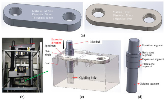
Figure 1.
Experimental setup: (a) specimen; (b) hydraulic machine; (c) fixture; (d) mandrel.

Table 1.
Chemical composition of the as-received Al7050 alloy.
Table 2.
Chemical composition of the as-received TB6 alloy.
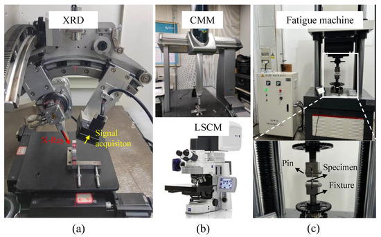
Figure 2.
Surface integrity and fatigue performance measurement: (a) residual stress; (b) surface morphology; (c) fatigue lifetime.
Table 3.
Parameters for fatigue tests.
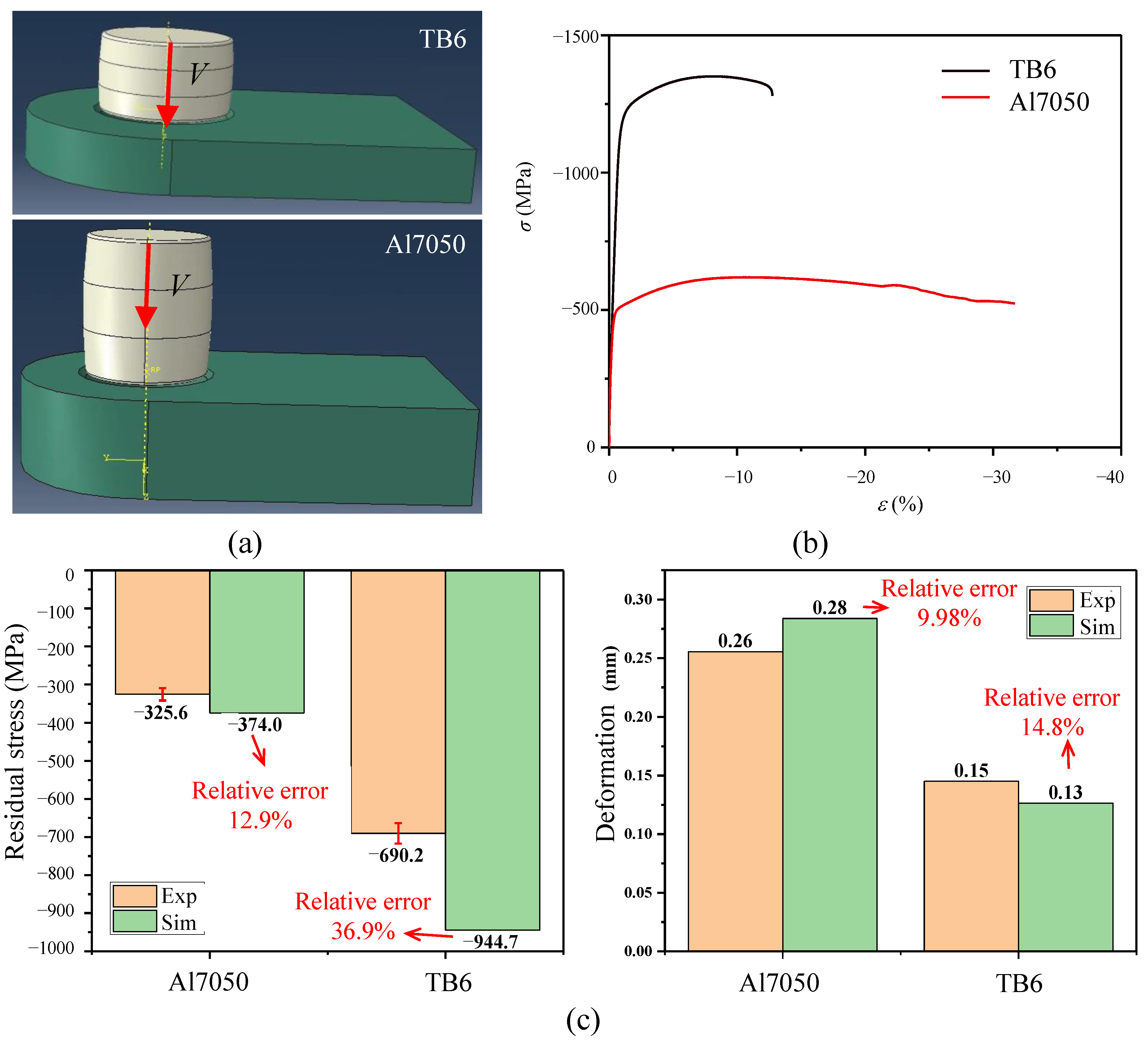
The technological principle of the DMCE process is shown in Figure 3; the upper image represents mandrel and the lower image represents hole-involved part. In the DMCE process, the mandrel passes through the hole along its axis with a constant velocity. As shown in this figure, there are 11 independent parameters in the DMCE process, i.e., 6 mandrel structural parameters, 4 relative structural parameters and 1 extrusion parameter, as listed in Table 4. It is costly to simultaneously consider all 11 parameters in experiments. Therefore, this work eliminates non-significant parameters through numerical modeling and simulations. The finite element models of the DMCE process were constructed using the ABAQUS 2021 software, as shown in Figure 4a. The hardness of W18Cr4V, TB6 and Al7050 were measured by using a micro Vickers tester with 10 kgf pressure and 15 s dwell time. The hardness values are, respectively, 844 HV, 353 HV and 153 HV for W18Cr4V, TB6 and Al7050. In other words, the hardness of mandrel is 2.39 and 5.52 times the hardness of TB6 and Al7050 specimens. Therefore, the mandrel was defined as analytical rigid body in simulations. The elastic properties of Ti and Al specimens are from the Handbook of Aeronautical Materials. In view of that the near-hole-wall materials are under compression conditions in the DMCE process, the plastic and damage properties were defined according to the truly obtained stress–strain curves from compression tests, as shown in Figure 4b and Table 5. The compression tests were performed by using the AGS-X 100kN universal testing machine (manufacturer: Shimadu Co. Ltd. in Kyoto, Japan) with Φ6 mm × 10 mm rod specimens and a constant 0.001 s−1 strain rate, 3 times repetitions were performed for each material to obtain reliable mechanical responses. The friction coefficients between mandrel and specimens were measured by using the UMT5 friction–abrasion testing machine (manufacturer: Bruker Co. Ltd. in Massachusetts, USA) with parameters, i.e., 2 N pressure, 10 mm stroke and 1 mm/s speed, as listed in Table 5. Moreover, the boundary conditions are defined as: (a) the mandrel and hole are coaxial, (b) the end face of specimen is fixed and the side faces of specimen are in symmetry along the hole axis, (c) the mandrel moves to specimen along its axis with a constant speed. The static, general step and C3D4 element were used. In order to balance the cost and precision in simulations, the globally coarse (~2 mm), hole wall locally fine (~0.5 mm) meshing strategy was used. The stress, strain and displacement values of elements can be obtained directly from the FEM simulations, and then the surface tangential residual stresses and radial deformations of hole walls can be calculated.
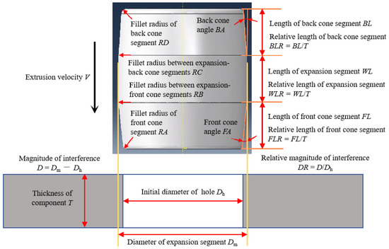
Figure 3.
Technological principle of the DMCE process.
Table 4.
Independent parameters of the DMCE process.
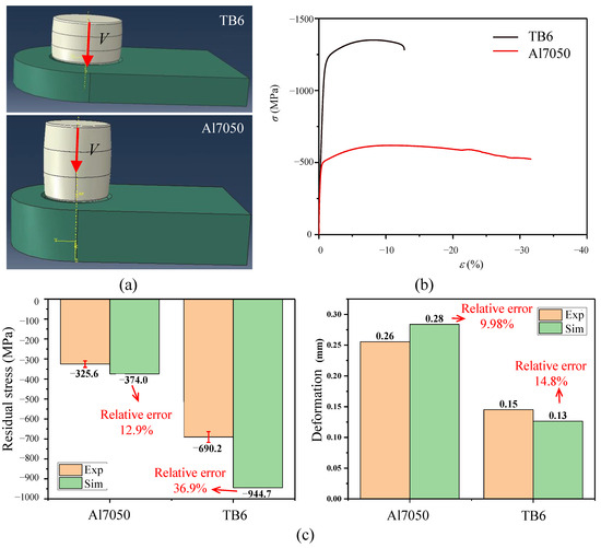
Figure 4.
Numerical modeling for DMCE process: (a) FEM models; (b) stress–strain curves; (c) model verification.
Table 5.
Mechanical, damage and friction parameters.
DMCE experiments and simulations were carried out to verify the numerical models and the used parameters are listed in Table 6. The mean surface tangential residual stresses and the mean radial deformations obtained by experiments and simulations were compared to evaluate the accuracy of numerical models. As shown in Figure 4c, the relative errors of simulated residual stresses are, respectively, 12.9% and 36.9% for Al and Ti alloys, and the relative errors of simulated deformations are, respectively, 9.98% and 14.8% for Al and Ti alloys, which are sufficient in this work to screen out significant process parameters.
Table 6.
Parameters used to verify the numerical models.
3. Fatigue Enhancement Mechanism of the DMCE Process
This work first screens out significant process parameters via cost-effective simulations and then investigates the specific fatigue enhancement mechanism of significant parameters on the DMCE process via reliable experiments.
3.1. Screening of Significant Parameters
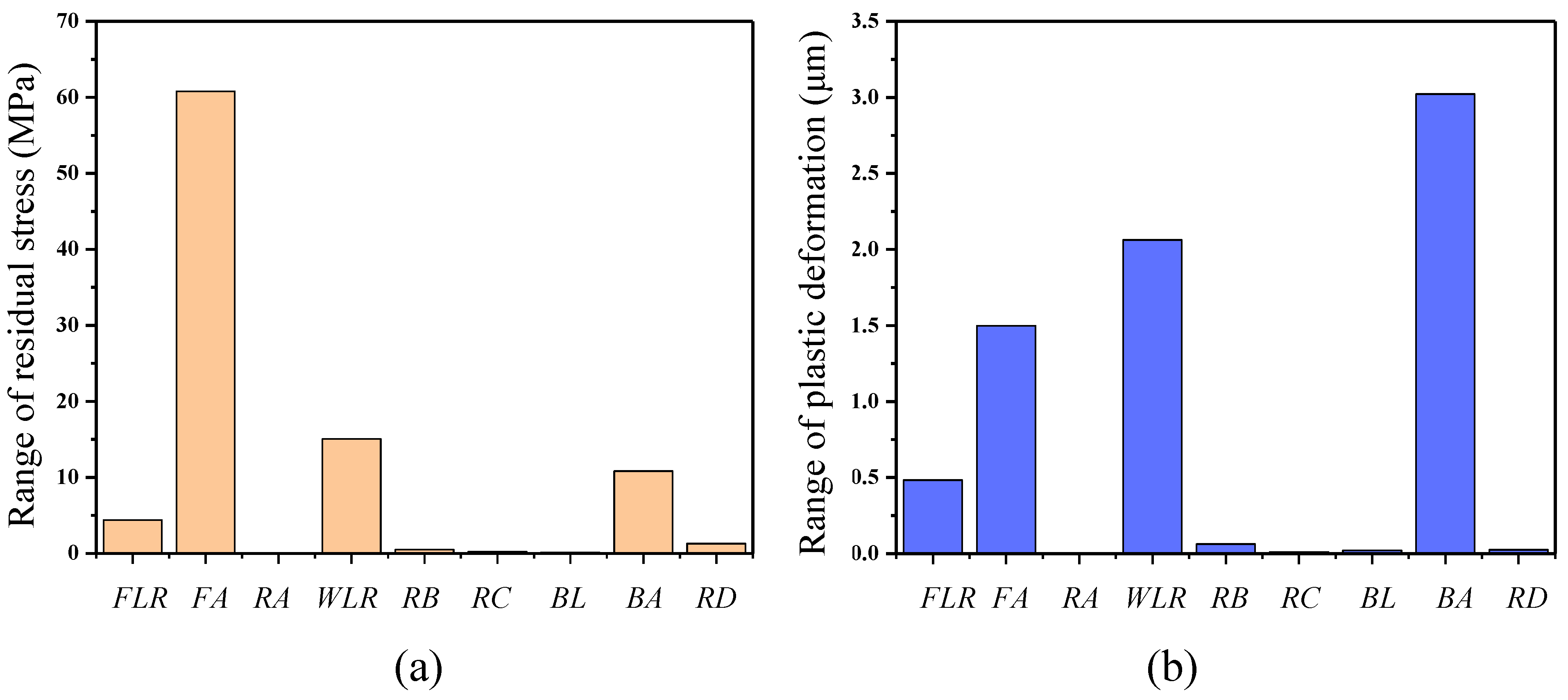
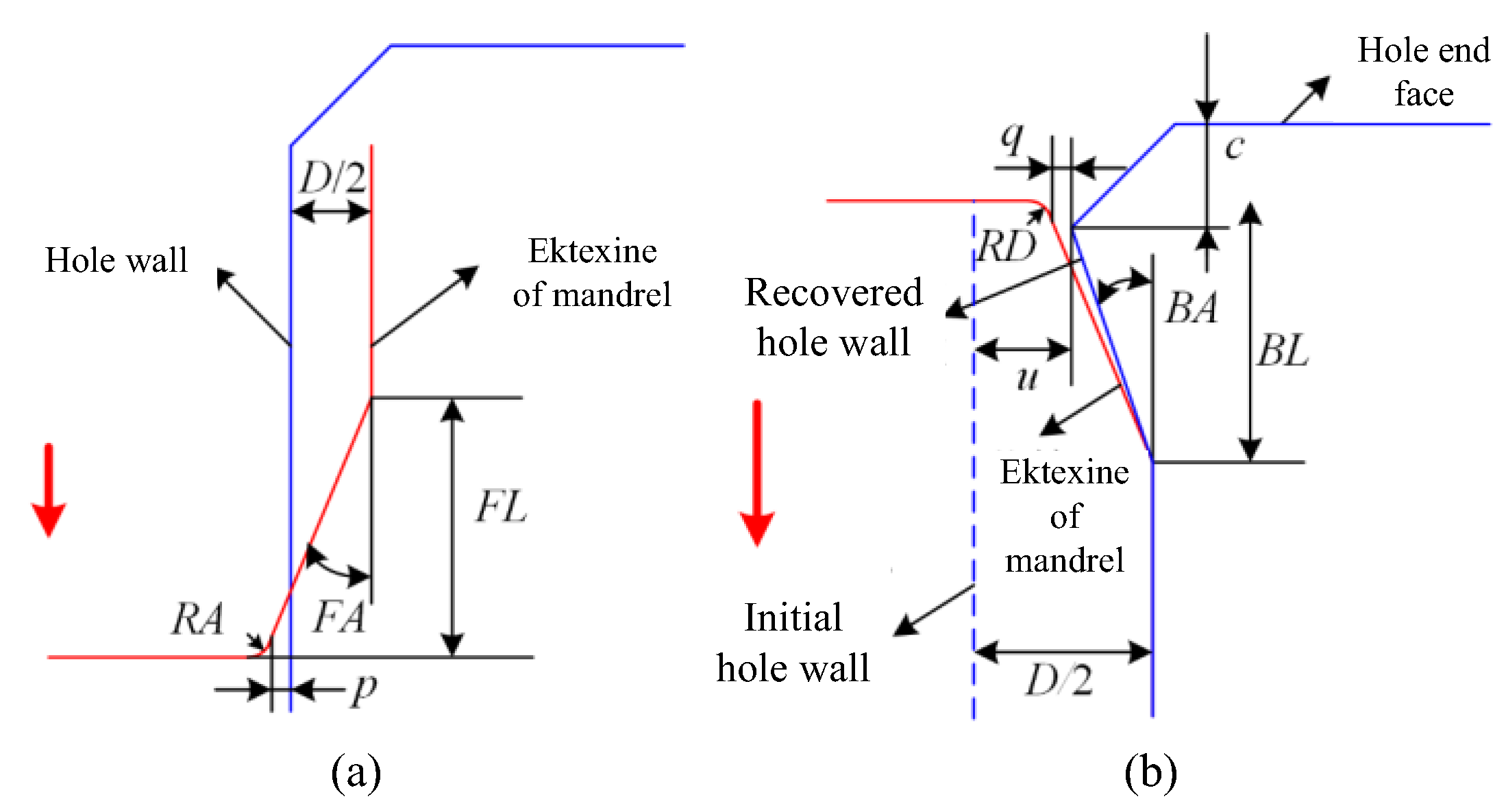
Among the 11 independent parameters of the DMCE process, D and V are universally acknowledged to have a significant influence on the fatigue enhancement effect, while the other nine mandrel structural parameters are less studied. The magnitude of interference D directly influences the deformation degree and in turn, influences the induced residual stress and final fatigue performance [35,36]. The extrusion speed V influences the strain rate and in turn, influences the deformation uniformity and induced residual stress [37]. Therefore, single-factor simulations with nine mandrel structural parameters were carried out to screen out the significant mandrel structural parameters, and the simulation scheme is listed in Table 7. A parameter can be judged to be non-significant if any one of the following conditions is met: (a) the independent influence of a parameter on residual stress and plastic deformation is negligible; (b) the independent influence of a parameter can be completely eliminated by optimizing other parameters. The influence degrees of the mandrel structural parameters on the mean tangential residual stress and the mean radial plastic deformation of the hole walls after the DMCE process were compared, as shown in Figure 5 (taking Al7050 alloy as an example). As can be seen in this figure, in comparison to FA, BA and WLR, the influence of the other six mandrel structural parameters on the surface integrity of the hole wall is small. The influences of RA, RB, RC and RD are almost negligible. The influence of FL/FLR is derived from the thrusting effect of the front cone segment fillet corner on the hole wall, which causes surface scratch and can be avoided by facilitating a positive distance p between the front cone segment fillet corner to the hole wall, as shown in Figure 6a and Equation (1). Similarly, in order to avoid the adverse effect of the back cone segment fillet corner on the hole wall, the distance q between the fillet corner to the hole wall should always be positive, as shown in Figure 6b and Equation (2).
Table 7.
Simulation scheme for significant parameter screening.

Figure 5.
Influence degree comparison of mandrel structural parameters: (a) mean tangential residual stress; (b) mean radial plastic deformation.
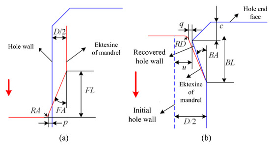
Figure 6.
The limitation of mandrel structural parameters: (a) front cone segment; (b) back cone segment.
In Equation (2), umin is the minimum radial resilience value after expansion, which was obtained from the simulations. According to Figure 5 and Figure 6 and Equations (1) and (2), the significant mandrel structural parameters can be screened out, i.e., FA, BA and WL/WLR. On this basis, combining the common low-cost targets in industries, the values of other mandrel structural parameters can be determined, as listed in Table 8.
Table 8.
The values of non-significant mandrel structural parameters.
3.2. Influence of Significant Parameters on the Surface Integrity of the Hole Wall
Single-factor experiments of the significant parameters, i.e., FA, BA, WLR, DR and V were performed to investigate the fatigue enhancement mechanism of the DMCE process, and the experimental scheme is listed in Table 9.
Table 9.
DMCE experiments for fatigue enhancement mechanism investigation.
3.2.1. Influence on the Tangential Residual Stress of the Hole Wall
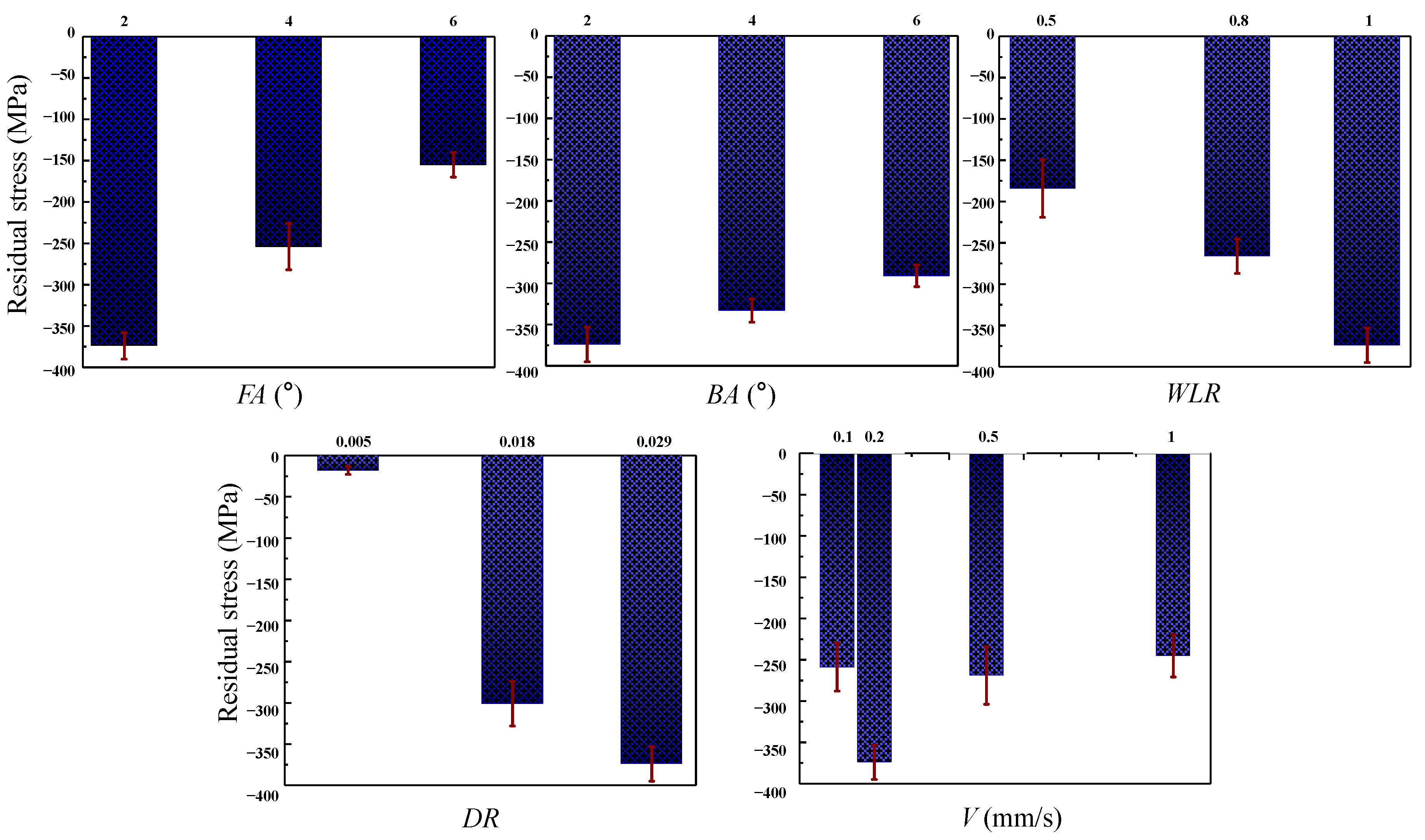
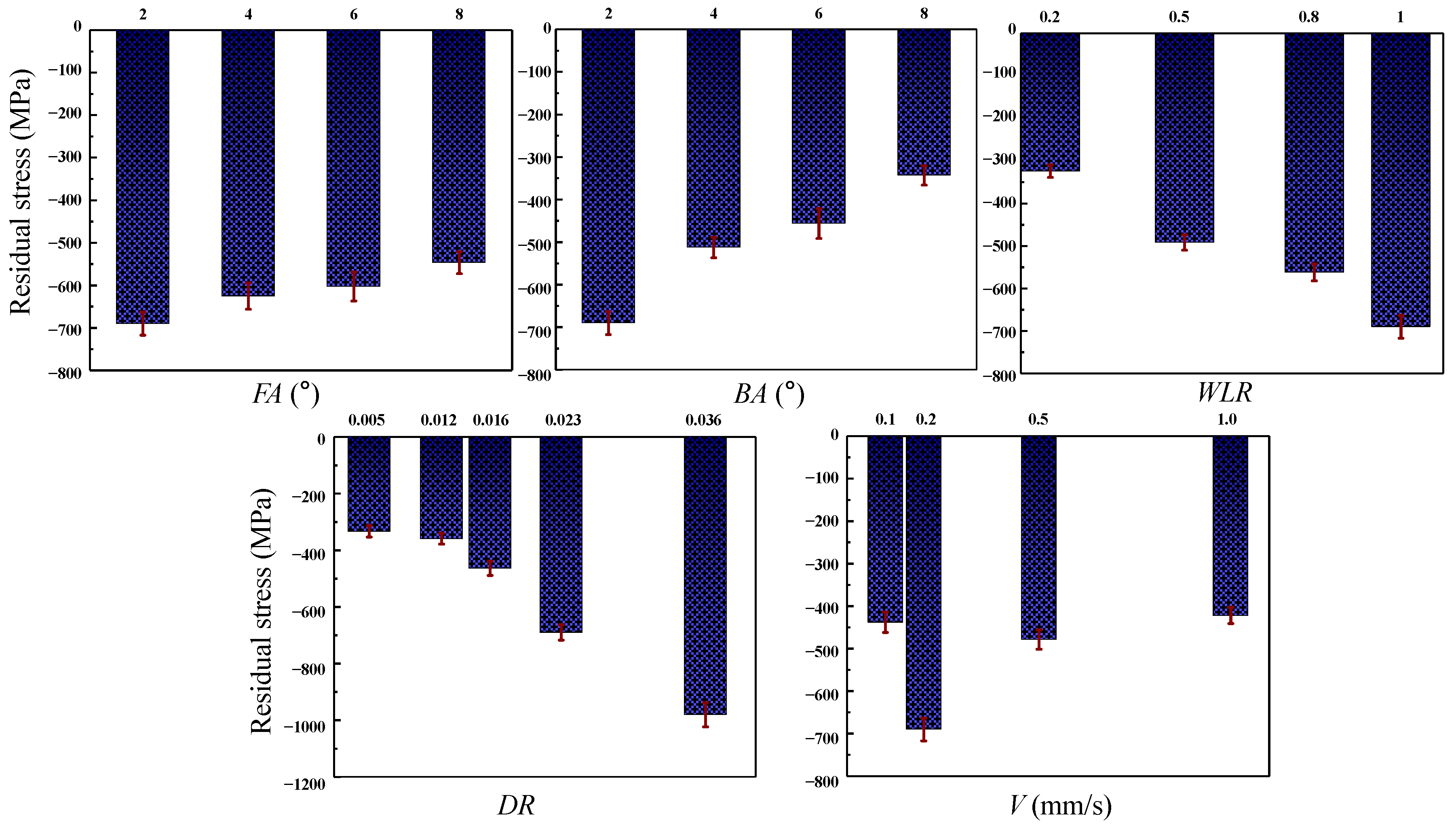
The influence of the significant DMCE parameters on the mean tangential residual stress of Al and Ti hole walls after expansion are shown in Figure 7 and Figure 8, respectively. As shown in Figure 7, the mean tangential residual stresses of the hole wall are compressive after the expansion due to the compression effect of the mandrel. With an increase in the front cone angle FA, the compressive residual stress continuously decreases. This is because the increase in FA accelerates the deformation process of the hole wall, resulting in inadequate dislocation accumulation and, therefore, smaller compressive residual stress [21,30]. With an increase in the back cone angle BA, the compressive residual stress continuously decreases. This is because an increase in BA promotes the material recovery and stress release of the hole wall after expansion. With an increase in the expansion segment length WL/WLR, the compressive residual stress continuously increases. This is because the increase in WL/WLR extends the retention time of the material deformation and then increases the dislocation density. Moreover, with the increase in interference magnitude, the compressive residual stress continuously increases. This is because the increase in WL/WLR promotes the deformation degree and dislocation density. However, there is no obvious positive or negative correlation relationship between the extrusion speed and residual stress. With the increase in extrusion velocity V, the compressive residual stress first increases and then decreases. As shown in Figure 8, the influence mechanism of the DMCE parameters on the TB6 hole are the same as that of the Al7050 alloy.
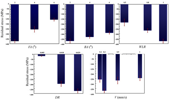
Figure 7.
The influence of DMCE process on the tangential residual stress of Al hole wall.

Figure 8.
The influence of DMCE process on the tangential residual stress of Ti hole wall.
3.2.2. Influence on the Radial Plastic Deformation of the Hole Wall
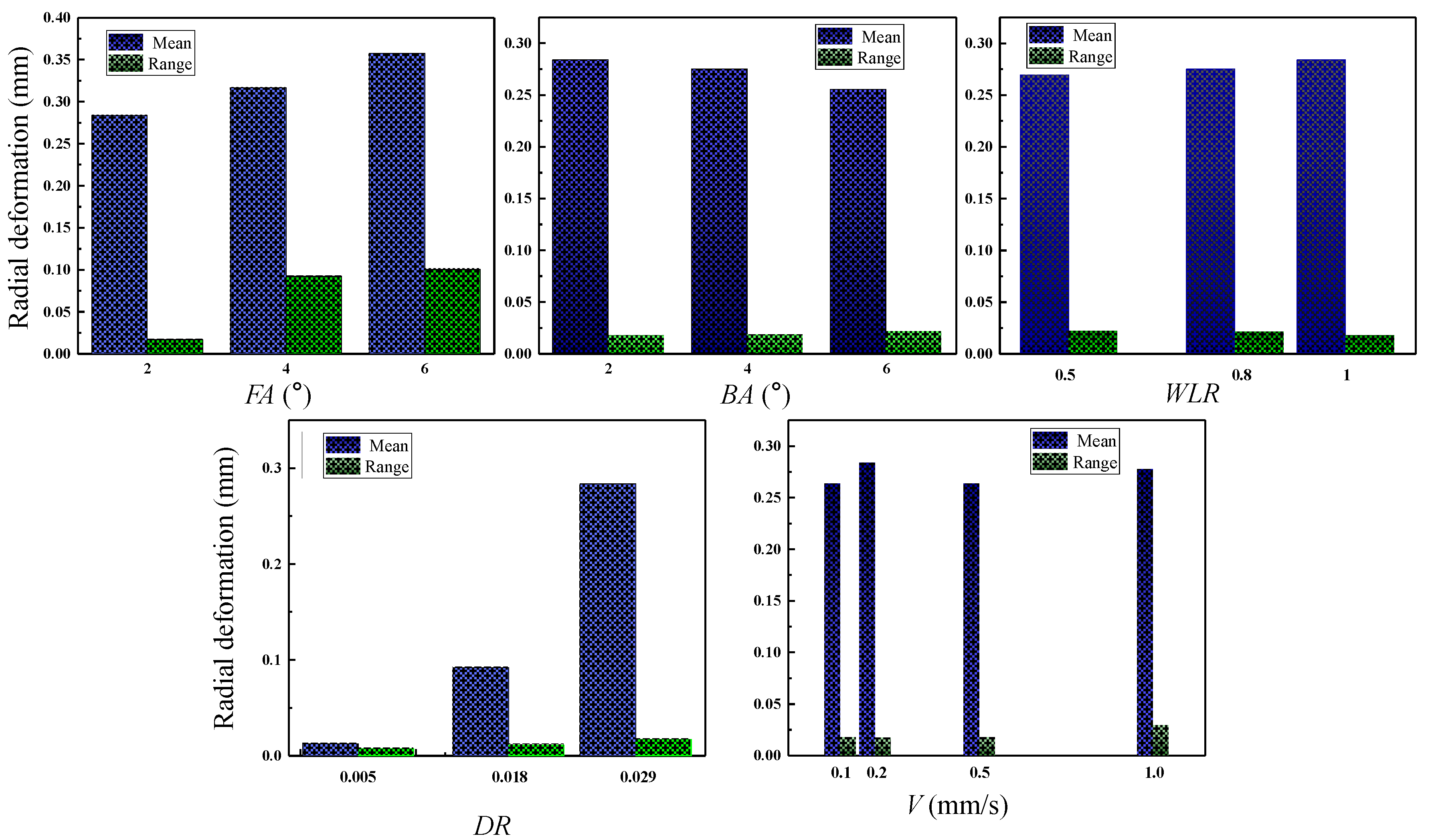
In order to directly evaluate the influence of the DMCE process parameters on the radial deformation field of the hole wall, this work focuses on the absolute value of the plastic deformations. The influences of the significant DMCE parameters on the mean and range of the radial plastic deformations of Al and Ti hole walls after expansion are shown in Figure 9 and Figure 10, respectively. As shown in Figure 9, with the increase in FA, the mean radial plastic deformation increases and the range of deformations extends. This is because the larger front cone angle improves the deformation rate, which increases the mean deformation due to the inertial effect of material flow and reduces the deformation uniformity. The increased radial deformation leads to a thicker plastic strengthening layer, which brings more obstacles to crack propagation and, therefore, improves the fatigue resistance of holes-involved specimens. With the increase in BA, the mean of plastic deformations decreases but its range increases. This is because the larger back cone angle speeds up the material recovery, which increases the material recovery degree, decreases the mean plastic deformation, and reduces the deformation uniformity. With the increase in WL/WLR, the mean of plastic deformation increases but its range decreases. This is because the longer expansion segment extends the retention time of overall deformation, which promotes dislocation accumulation and deformation uniformity, resulting in a greater mean and a smaller range of plastic deformations. With the increase in D/DR, both the mean and range of plastic deformations increase. This is because the larger interference magnitude directly improves the overall deformation and plastic deformation, which brings out more deformation uniformity. Moreover, the mean radial plastic deformation seems irrelevant to the extrusion velocity while the range of plastic deformations is positively correlated with extrusion velocity. This is because the higher velocity leads to more deformation uniformity. As compared to the Al alloy, except for the interference magnitude, other parameters show a very small influence on the mean and range of radial plastic deformations of the hole made by TB6, which originates from the higher strength and hardness of the Ti alloy, therefore, it appears as a weaker inertial effect in the material deformation.

Figure 9.
The influence of DMCE process on the radial deformation of Al hole wall.
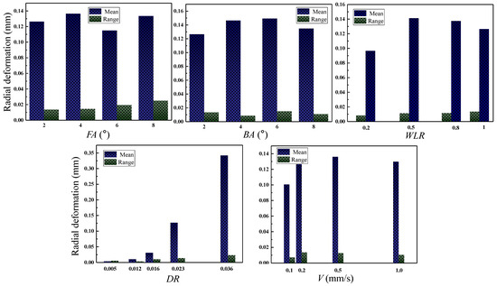
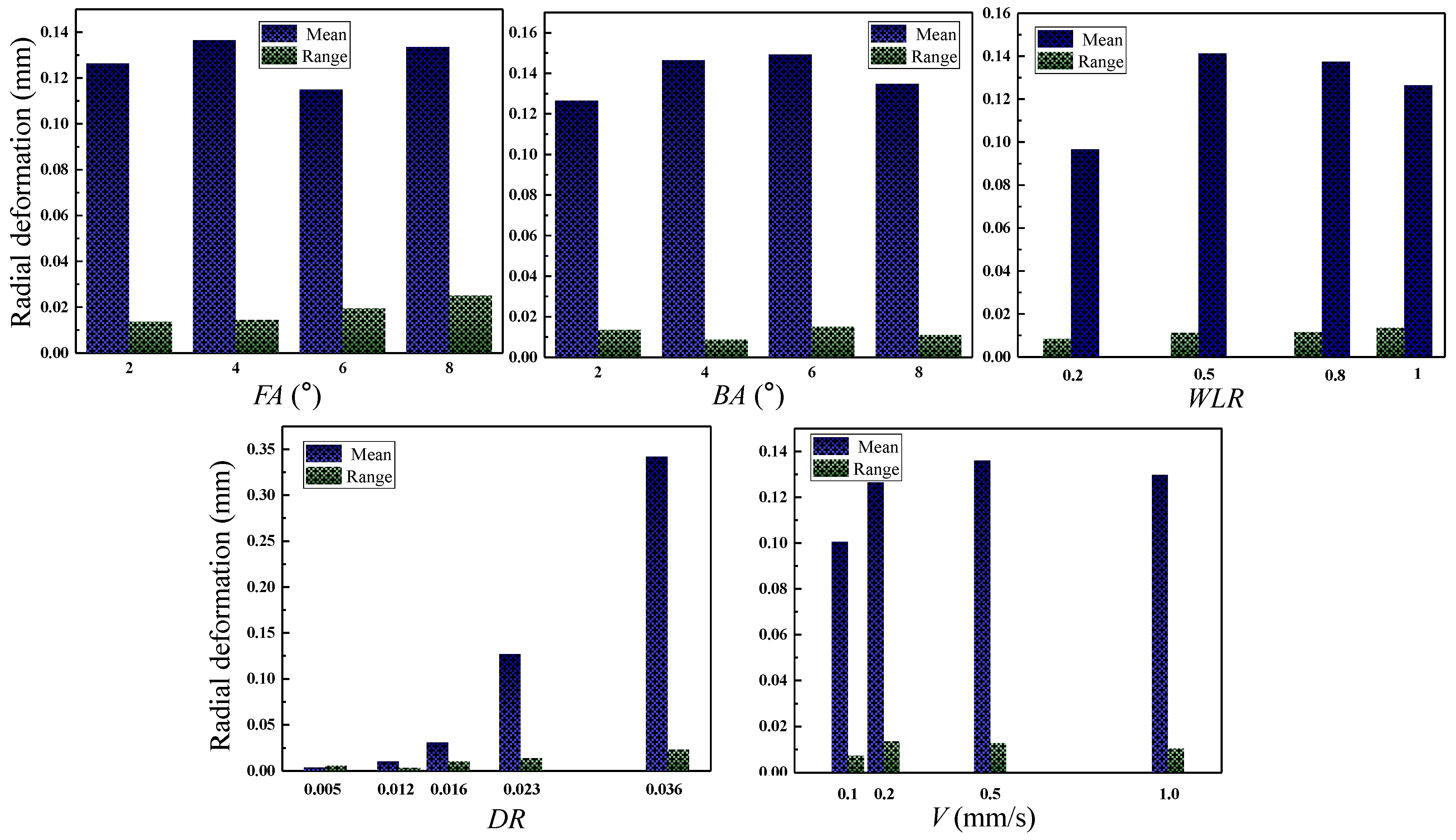
Figure 10.
The influence of DMCE process on the radial deformation of Ti hole wall.
3.2.3. Influence on the Surface Morphology of the Hole Wall
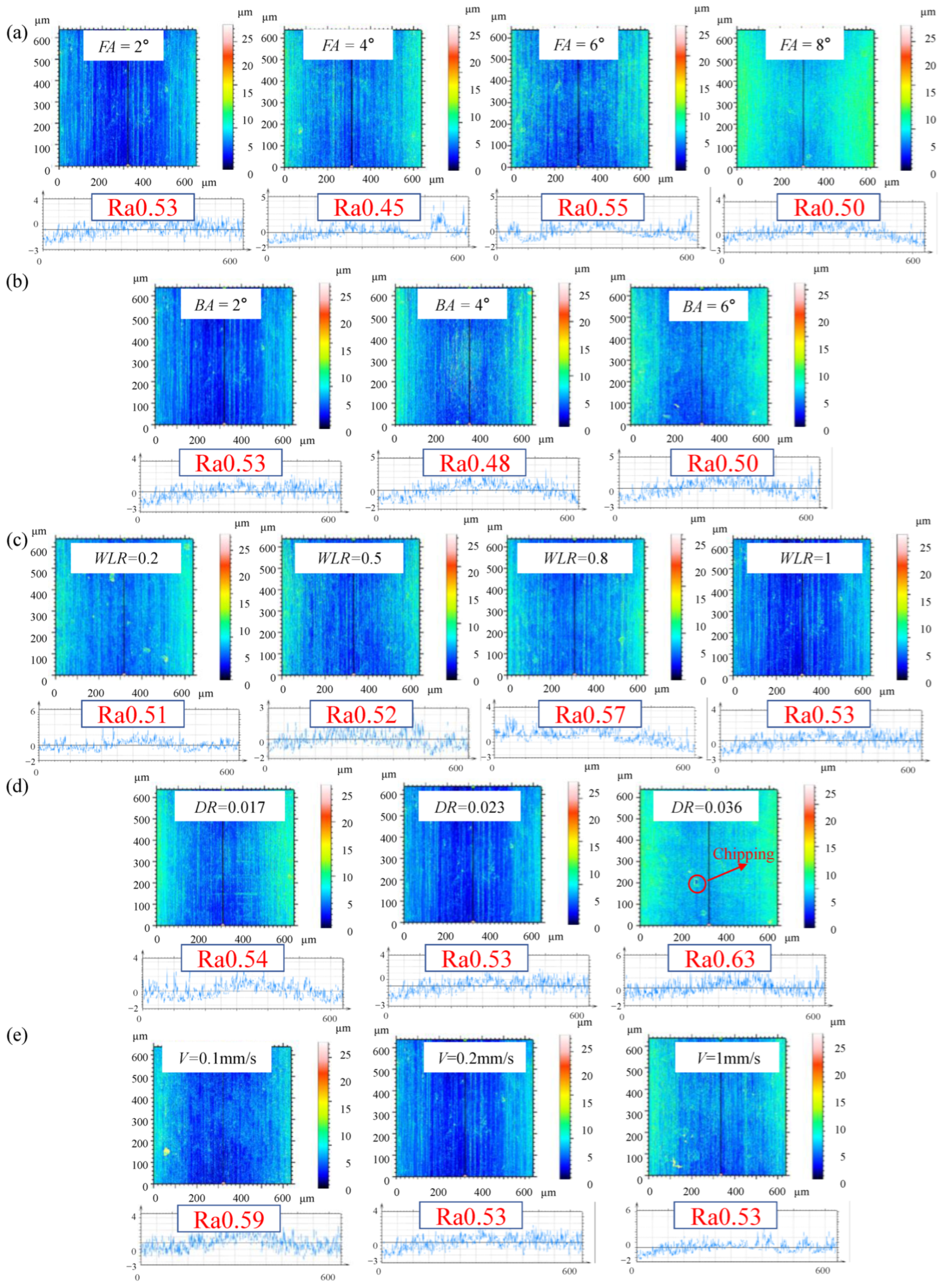
The influences of the significant DMCE parameters on the surface morphology of Al and Ti hole walls after expansion are, respectively, shown in Figure 11 and Figure 12. both Al and Ti hole walls show slight axial scratches after expansion. All the surface roughness of the Ti hole walls still meets the Ra0.8 requirement, while the roughness of some Al hole walls does not. As shown in Figure 11, with the increase in FA, the surface roughness of the hole wall decreases. This is because the larger front cone angle means the shorter contact time between the front cone segment and the hole wall, resulting in less scratch and better surface quality. With the increase in BA, the surface roughness of the hole wall decreases. This is because the larger back cone angle means the shorter contact time between the back cone segment and the hole wall, resulting in less scratch and better surface quality. With the increase in WL/WLR, the surface roughness of the hole wall increases. This is because the longer expansion segment means a longer contact time between the expansion segment and the hole wall, resulting in more scratches and worse surface quality. With the increase in D/DR, the surface roughness of the hole wall increases. This is because a larger interference magnitude leads to more deformation non-uniformity and more scratches, resulting in worse surface quality. With the increase in V, the surface roughness of the hole wall increases. This is because the higher extrusion speed leads to a faster material deformation rate, resulting in more deformation non-uniformity and, therefore, worse surface quality. As compared to the Al alloy, the parameters appear to have little effect on the surface morphology of the Ti hole wall, which originates from its higher hardness and, therefore, a harder change of damage degree during the DMCE process. It is worth noting that obvious material chipping was found when the relative interference magnitude DR equals 0.036, which is normal due to the limitation of the ultimate deformation capacity of metallic materials.
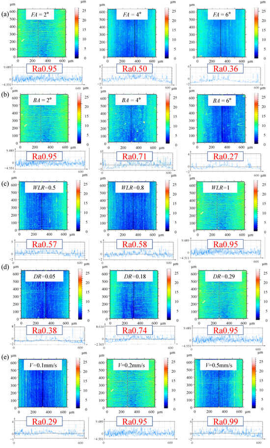
Figure 11.
The influence of DMCE process on the surface morphology of Al hole walls: (a) front cone angle; (b) back cone angle; (c) relative length of expansion segment; (d) relative magnitude of interference; (e) extrusion velocity.

Figure 12.
The influence of DMCE process on the surface morphology of Ti hole walls: (a) front cone angle; (b) back cone angle; (c) relative length of expansion segment; (d) relative magnitude of interference; (e) extrusion velocity.
3.3. Influence of Significant Parameters on the Fatigue Life of Hole-Involved Components
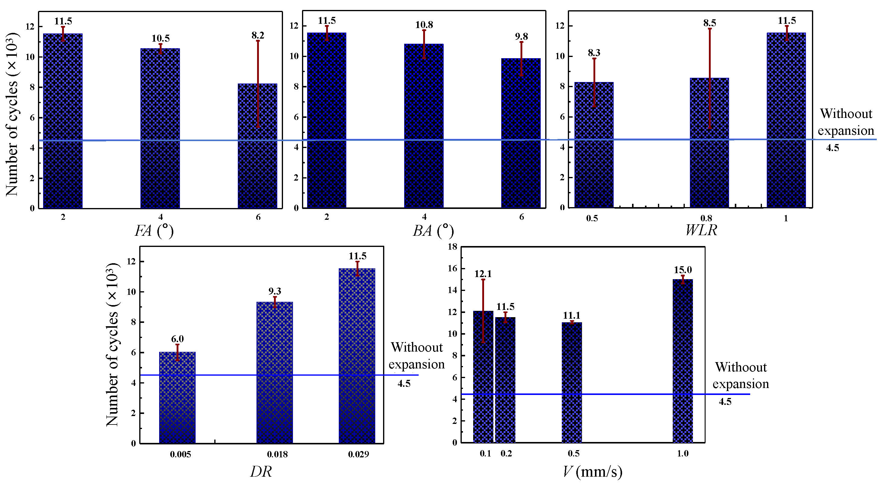
The influences of the significant DMCE parameters on the fatigue lifetimes of Al and Ti two-hole-involved specimens after expansion are shown in Figure 13 and Figure 14, respectively; the fatigue lifetimes of both Al and Ti alloys were improved. As shown in Figure 13, with the increase in the front cone angle, back cone angle and expansion segment length, the fatigue lifetimes of the two-hole-involved Al and Ti alloys, respectively, decrease, and decrease and increase, which is consistent with the varying tendencies of those parameters on the mean tangential residual stress of hole wall after expansion. This is because the increased compressive residual stress is able to contract larger tension stress, which restrains the degree of stress concentration and hinders crack initiation, and in turn, improves the fatigue lifetime of specimens. Regarding the interference magnitude, the fatigue life of the Al specimen continuously increases, and the fatigue life of the Ti specimen first increases and then decreases due to the appearance of surface chipping. It is believed that there is also an inflection point of interference magnitude for Al alloys. However, with the increase in extrusion velocity, the fatigue life of the Al specimen first decreases then increases and achieves the maximum value when the extrusion velocity equals 1 mm/s; the fatigue life of the Ti specimen first increases then decreases and achieves the maximum value when the extrusion velocity equals 0.2 mm/s, which is originated from the coupling effect of residual stress, plastic deformation and surface quality.
Figure 13.
The influence of DMCE process on the fatigue life of Al specimen.

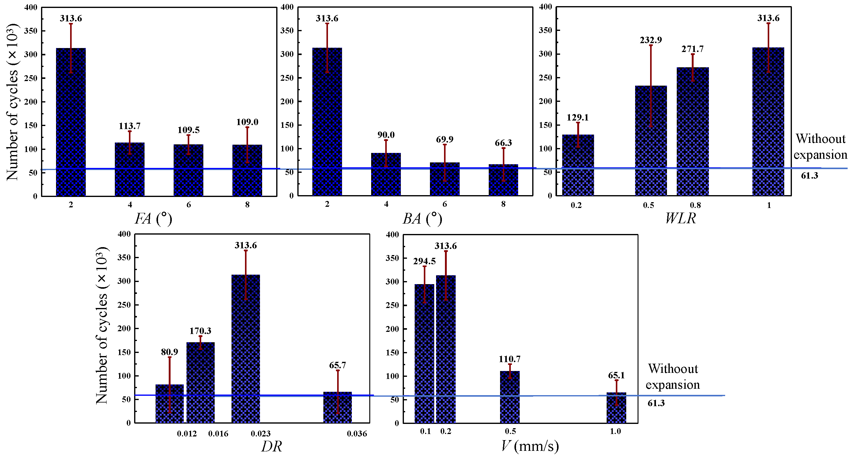
Figure 14.
The influence of DMCE process on the fatigue life of Ti specimen.
4. Fatigue Lifetime Prediction and Optimization of the DMCE Process
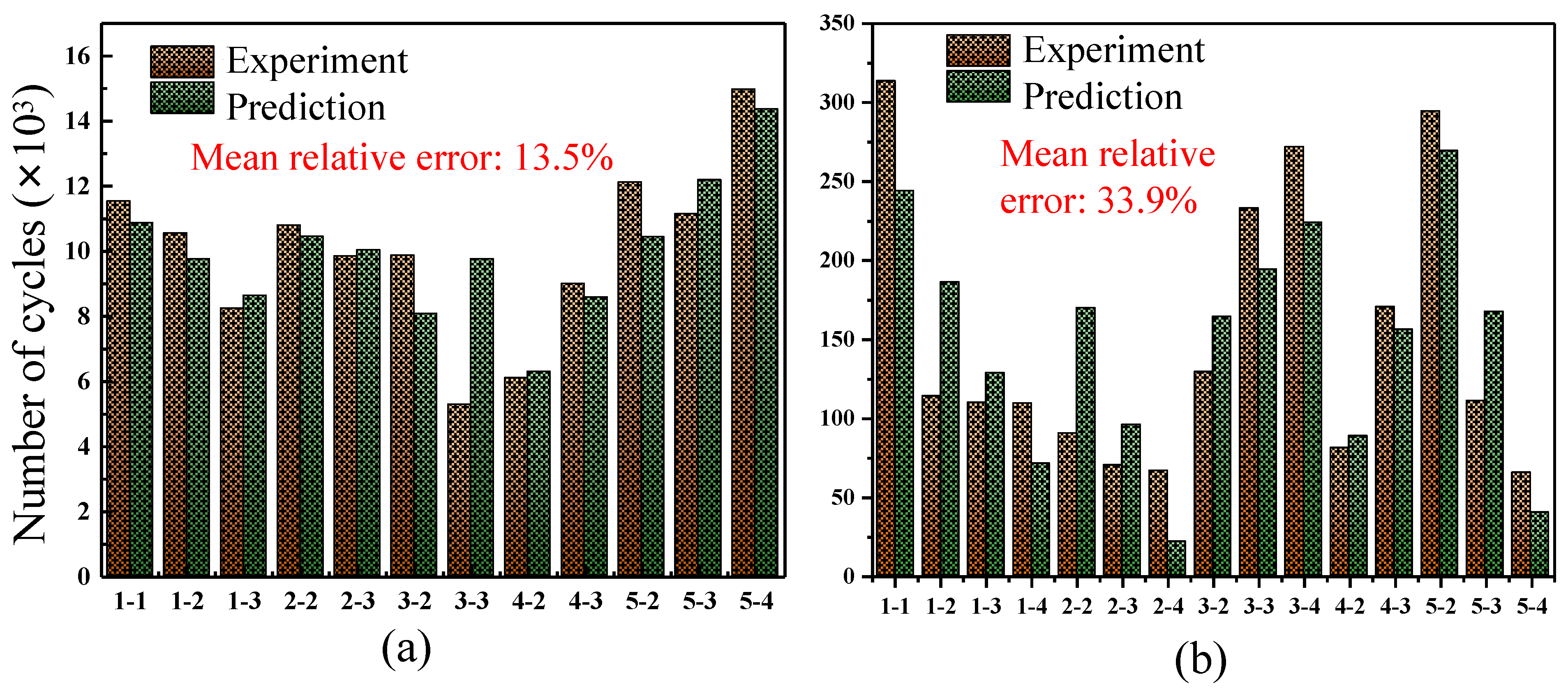
According to the experimental results in Section 3, the fatigue lifetime prediction models of two-hole-involved Al and Ti specimens were established by multiple linear regression, as listed in Equations (3) and (4). The prediction results were compared with the experimental results, as shown in Figure 15, the mean prediction errors are, respectively, 13.5% and 33.9% for the Al and the Ti alloys.
Figure 15.
Fatigue lifetime prediction of two-hole-involved specimens after DMCE process: (a) Al specimen; (b) Ti specimen.
According to Section 3, the decrease in the mandrel front cone angle, the decrease in the mandrel back cone angle and the extension of the mandrel expansion segment are beneficial to the fatigue lifetime improvement of Al and Ti alloys; therefore, 2°, 2° and 1 can be determined as the optimal values of front cone angle, back cone angle and expansion segment length for Al and Ti alloys. The increase in interference magnitude is also beneficial to the fatigue life improvement while there is an ultimate value. Based on experimental results, 0.029 and 0.023 can be determined as the optimal interference magnitude values for Al and Ti alloys. Moreover, there is no obvious correlation between extrusion velocity and fatigue lifetime, 1 mm/s and 0.2 mm/s can be determined as the optimal values of extrusion velocity for Al and Ti alloys. The optimal values of significant parameters are listed in Table 10, and 2.33 and 4.12 times fatigue life improvement were achieved for Al and Ti alloys.
Table 10.
The optimal DMCE parameters for Al and Ti alloys.
Compared with the existing DMCE studies that concentrate on partial process parameters [32,38,39], this work comprehensively considers all 11 independent parameters, screening out significant parameters by cost-effective simulations, and exploring mechanisms via reliable experiments. Compared with the existing DMCE studies that concentrate on one specific material [40,41], this work comparatively investigates the similarities and differences of the fatigue enhancement mechanism of Al7050 and TB6 alloys and analyzes the reason why differences appear, which is helpful for the fatigue enhancement mechanism investigation and the process optimization of other materials.
5. Conclusions
This paper comprehensively investigates the fatigue enhancement mechanism of the DMCE process on the holes of lightweight and high-strength alloys, aiming to promote the application efficiency of this technique in aviation industries and reduce the waste of repeated attempts. Two-hole-involved Al7050 and TB6 specimens simplified from actual aviation structural parts were selected as samples, and their dimensional parameters and fatigue testing parameters were determined based on actual working conditions. The following conclusions can be drawn:
- (1)
- Numerical models for the DMCE process were established with 12.9% and 36.9% relative errors for the mean tangential residual stress prediction of Al and Ti hole walls, and 9.98% and 14.8% relative errors for the mean radial plastic deformation prediction of Al and Ti hole walls. The numerical simulations were then performed to screen out five significant parameters (i.e., the mandrel front cone angle, the mandrel back cone angle, the mandrel segment length, the interference magnitude and the extrusion velocity) from eleven independent parameters and determine the limitation law of the other six parameters.
- (2)
- For both Al and Ti alloys, the influences of the DMCE parameters on the mean tangential residual stress of the hole wall are similar. The increase in the front cone angle increases the expansion rate of materials, resulting in less dislocation accumulation and, therefore, smaller compressive residual stress. The increase in the back cone angle increases the recovery rate of the material, resulting in more stress relief and, therefore, smaller compressive residual stress. The increase in the expansion segment length increases the holding time of material deformation, resulting in more dislocation accumulation and, therefore, larger compressive residual stress. The increase in the interference magnitude increases the plastic deformation degree, resulting in more dislocation accumulation and, therefore, larger compressive residual stress.
- (3)
- For the Al alloy, the increase in the front cone angle increases the expansion rate of the hole wall material, resulting in a more significant flow inertial effect and, therefore, larger radial plastic deformation. The increase in the back cone angle increases the recovery rate of hole wall material, resulting in more elastic recovery and, therefore, smaller plastic deformation. The increase in the expansion segment length increases the dislocation accumulation and, therefore, results in larger plastic deformation. The increase in the interference magnitude directly increases the overall plastic deformations. Comparatively, the cone angles and segment length show a slight influence on the hole wall of the Ti alloy due to its weaker inertial effect.
- (4)
- After expansion, all the Ti hole wall surfaces still meet the roughness requirement (Ra0.8) while some of the Al hole wall surfaces do not. For the Al alloy, a decrease in the cone angles and an increase in the cone segment length increase the contact time between the hole wall and mandrel, resulting in more scratches and worse surface quality. An increase in the interference magnitude and extrusion velocity decreases the deformation uniformity and, therefore, results in worse surface quality. Comparatively, the DMCE parameters show a slight influence on the surface morphology of the Ti hole wall due to its greater hardness.
- (5)
- The fatigue lifetimes of two-hole-involved Al and Ti specimens are significantly improved after DMCE processes. The fatigue enhancement regularity is basically the same with the regularity of compressive residual stress improvement. However, the fatigue enhancement effect shows a step-like decline when the surface chipping appears. Based on the experimental results, the fatigue life prediction models for the two-hole-involved Al and Ti specimens were generated with, respectively, 13.5% and 33.9% mean prediction errors. Furthermore, the optimal DMCE parameters for Al7075 and TB6 hole strengthening were achieved, which induced 374 MPa and 690 MPa compressive residual stresses on the walls of the Al and Ti holes. The two-hole-involved Al specimens after the DMCE process with optimal parameters performed an average of 15 × 103 cycles before failure under the fatigue condition with a 0.1 stress ratio and a 178 MPa maximum load, which means 3.33 times of lifetime as compared to the raw specimens without expansion. The two-hole-involved Ti specimen after the DMCE process with the optimal parameters performed 313.6 × 10³ cycles under the fatigue condition with a 0.1 stress ratio and a 300 MPa maximum load, which means 5.12 times of lifetime as compared to the raw specimens without expansion.
Author Contributions
Conceptualization, H.J., K.H., P.F. and J.Z.; methodology, H.J., L.H. and Z.C.; software, H.J. and M.T.; validation, H.J. and Z.C.; formal analysis, H.J. and L.H.; investigation, H.J., L.H., Z.C. and M.T.; resources, K.H. and J.Z.; data curation, H.J. and M.T.; writing—original draft preparation, H.J.; writing—review and editing, H.J.; visualization, H.J., L.H. and Z.C.; supervision, J.Z. and P.F.; project administration, K.H. and J.Z. All authors have read and agreed to the published version of the manuscript.
Funding
This research received no external funding.
Data Availability Statement
The datasets presented in this article are not readily available because the data are part of an ongoing study.
Conflicts of Interest
The authors declare no conflicts of interest.
References
- Shao, L.; Li, W.; Li, D.; Xie, G.; Zhang, C.; Zhang, C.; Huang, J. A Review on Combustion Behavior and Mechanism of Ti Alloys for Advanced Aero-Engine. J. Alloys Compd. 2023, 960, 170584. [Google Scholar] [CrossRef]
- Nagalingam, A.P.; Gopasetty, S.K.; Wang, J.; Yuvaraj, H.K.; Gopinath, A.; Yeo, S.H. Comparative Fatigue Analysis of Wrought and Laser Powder Bed Fused Ti-6Al-4V for Aerospace Repairs: Academic and Industrial Insights. Int. J. Fatigue 2023, 176, 107879. [Google Scholar] [CrossRef]
- Zhao, Q. High-Strength Titanium Alloys for Aerospace Engineering Applications: A Review on Melting-Forging Process. Mater. Sci. 2022, 845, 143260. [Google Scholar] [CrossRef]
- Madhavi, Y.; Rama Krishna, L.; Narasaiah, N. Corrosion-Fatigue Performance of Hard Anodized and MAO-Coated 2024-T3 and 7075-T6 Aerospace Al Alloys. Trans. Indian Inst. Met. 2021, 74, 2231–2243. [Google Scholar] [CrossRef]
- Li, S.; Yue, X.; Li, Q.; Peng, H.; Dong, B.; Liu, T.; Yang, H.; Fan, J.; Shu, S.; Qiu, F.; et al. Development and Applications of Aluminum Alloys for Aerospace Industry. J. Mater. Res. Technol. 2023, 27, 944–983. [Google Scholar] [CrossRef]
- Arhumah, Z.; Pham, X.-T. Microstructure and Thermal Mechanical Behavior of Arc-Welded Aluminum Alloy 6061-T6. J. Manuf. Mater. Process. 2024, 8, 110. [Google Scholar] [CrossRef]
- Li, X.; Zhao, P.; Niu, Y.; Guan, C. Influence of Finish Milling Parameters on Machined Surface Integrity and Fatigue Behavior of Ti1023 Workpiece. Int. J. Adv. Manuf. Technol. 2017, 91, 1297–1307. [Google Scholar] [CrossRef]
- Liu, J.; Sun, J.; Zaman, U.K.U.; Chen, W. Influence of Wear and Tool Geometry on the Chatter, Cutting Force, and Surface Integrity of TB6 Titanium Alloy with Solid Carbide Cutters of Different Geometry. J. Mech. Eng.-Stroj. Vestn. 2020, 66, 709–723. [Google Scholar] [CrossRef]
- Peng, L.; Wang, Z.; Sun, H.; Luo, T.; Li, X.; Geng, J.; Xia, P.; Li, Y.; Li, K.; Chen, D.; et al. Suppress Defect-Induced Plastic Instability to Achieve Superior Strength-Ductility Combination of Spray Formed 7050 Al Alloy. Mater. Des. 2024, 247, 113421. [Google Scholar] [CrossRef]
- De Salvo, J.G.J.; Afonso, C.R.M. Fatigue Strength and Microstructure Evaluation of Al 7050 Alloy Wires Recycled by Spray Forming, Extrusion and Rotary Swaging. Trans. Nonferrous Met. Soc. China 2020, 30, 3195–3209. [Google Scholar] [CrossRef]
- Deng, Z.; Sun, L.; Hao, F.; Zhang, B.; He, Y. An Improved Posture Evaluation Method for Cylindrical Intersecting Holes on Large Aerospace Components Based on Monocular Vision. Meas. Sci. Technol. 2022, 33, 055016. [Google Scholar] [CrossRef]
- Aamir, M. A Review: Drilling Performance and Hole Quality of Aluminium Alloys for Aerospace Applications. J. Mater. Res. Technol. 2020, 9, 12484–12500. [Google Scholar] [CrossRef]
- Fan, Y.; Huang, J.; Zhang, Y.; Huang, N.; Bi, Q.; Wang, Y. Improvement in Hole-Pose Error for Aerospace Drilling Applications Based on Hermite Surface Reconstruction and Manifold Error Similarity. Precis. Eng. 2023, 81, 22–35. [Google Scholar] [CrossRef]
- Liu, J.; Lin, X.; Feng, F.; Wang, Z.; Zhao, Z.; Bai, Z.; Zhang, J.; Feng, P.; Zhang, X. Study on the Surface Defect of Aluminum Alloy Hole Burnishing. Tribol. Int. 2023, 184, 108490. [Google Scholar] [CrossRef]
- Chen, Y.; Pan, X.; Wang, K.; Wang, F. Effects of Rivet Hole Arrangement on Fatigue Performance of Thin Sheets for Fuselage: DIC and Numerical Calculation. Thin-Walled Struct. 2022, 170, 108550. [Google Scholar] [CrossRef]
- Zhao, T. Creep-Fatigue Rupture Mechanism and Microstructure Evolution around Film-Cooling Holes in Nickel-Based DS Superalloy Specimen. Intermetallics 2021, 139, 107359. [Google Scholar] [CrossRef]
- Su, R.; Li, J.; Liu, W.; Xu, C.; Gao, L.; Liang, X.; Wu, D.; Huang, X.; Dong, H.; Ma, H. Investigation on Fatigue Failure of Split-Sleeve Cold Expansion Holes of 7075-T651 Aluminum Alloy. Mater. Today Commun. 2023, 35, 106290. [Google Scholar] [CrossRef]
- Wang, X.; Xu, C.; Chen, X.; Hu, D.; Hu, B.; Hu, R.; Gu, Y.; Tang, Z. Effect of Cold Expansion on High-Temperature Low-Cycle Fatigue Performance of the Nickel-Based Superalloy Hole Structure. Int. J. Fatigue 2021, 151, 106377. [Google Scholar] [CrossRef]
- Liu, J.; Shao, X.J.; Liu, Y.S.; Yue, Z.F. Effect of Cold Expansion on Fatigue Performance of Open Holes. Mater. Sci. Eng. A 2008, 477, 271–276. [Google Scholar] [CrossRef]
- Feng, F.; Zhao, Z.; Wang, Z.; Li, B.; Lin, X.; Zhang, J.; Feng, P.; Zhang, X. A Calculation Method for Residual Stress of Cold Expanded Hole Based on Measured Springback. Measurement 2023, 218, 113262. [Google Scholar] [CrossRef]
- Wang, C.; Zou, F.; Zhou, E.; Fan, Z.; Ge, E.; An, Q.; Ming, W.; Chen, M. Effect of Split Sleeve Cold Expansion on Microstructure and Fatigue Performance of 7075-T6 Aluminum Alloy Holes. Int. J. Fatigue 2023, 167, 107339. [Google Scholar] [CrossRef]
- Dang, Z.; Peng, Y.; Yang, R.; Yan, L.; Gan, X.; Ge, D. Experimental Study on the Effect of Reaming on the Fatigue Life of Split-Sleeve Cold-Expanded Ti–6Al–4V Alloy Components. Int. J. Fatigue 2024, 188, 108521. [Google Scholar] [CrossRef]
- Akkurt, A. Comparison of Roller Burnishing Method with Other Hole Surface Finishing Processes Applied on AISI 304 Austenitic Stainless Steel. J. Mater. Eng. Perform. 2011, 20, 960–968. [Google Scholar] [CrossRef]
- Nguyen, T.-T. Multi-Response Performance Optimization of Burnishing Operation for Improving Hole Quality. J. Braz. Soc. Mech. Sci. Eng. 2021, 43, 560. [Google Scholar] [CrossRef]
- Zheng, G.; Cao, Z.; Zuo, Y. A Dynamic Cold Expansion Method to Improve Fatigue Performance of Holed Structures Based on Electromagnetic Load. Int. J. Fatigue 2021, 148, 106253. [Google Scholar] [CrossRef]
- Geng, H.; Xu, X.; Cao, Q.; Lai, Z.; Li, L. Improving the Fatigue Performance of AZ31 Sheet with Hole via Electromagnetic Cold Expansion Process. Int. J. Adv. Manuf. Technol. 2022, 120, 5057–5071. [Google Scholar] [CrossRef]
- Zheng, G.; Cao, Z.; Zuo, Y. Fatigue Life Enhancement Mechanism and Lifetime Prediction of AA6061-T6 Open-Holed Sheet Treated by Electromagnetic Driving Dynamic Cold Expansion. Mater. Today Commun. 2022, 33, 104841. [Google Scholar] [CrossRef]
- Andrew, D.L.; Han, H.; Ocampo, J.; Alaeddini, A.; Thomsen, M. Characterization of Residual Stresses from Cold Expansion Using Spatial Statistics. Fatigue Fract. Eng. Mat. Struct. 2021, 44, 101–114. [Google Scholar] [CrossRef]
- Zheng, G.; Cao, Z.; Talemi, R. Investigation on Fatigue Performance of Open-hole Plates Treated by Dynamic Cold Expansion under Large Expansion Size Based on Electromagnetic Loading. Fatigue Fract. Eng. Mat. Struct. 2023, 46, 4178–4198. [Google Scholar] [CrossRef]
- Cao, X.; Zhang, P.; Liu, S.; Lei, X.-L.; Wang, R.-Z.; Zhang, X.-C.; Tu, S.-T. A Novel Hole Cold-Expansion Method and Its Effect on Surface Integrity of Nickel-Based Superalloy. J. Mater. Sci. Technol. 2020, 59, 129–137. [Google Scholar] [CrossRef]
- Liu, F.; Su, H.; Liang, Y.; Xu, J. Fatigue Performance on 7050 Aluminum Alloy by Using Ultrasonic Vibration-Assisted Hole Expansion Strengthening. Int. J. Adv. Manuf. Technol. 2023, 128, 5153–5165. [Google Scholar] [CrossRef]
- Guan, M.; Xue, Q.; Zhuang, Z.; Hu, Q.; Qi, H. Experimental Study of Reaming Sizes on Fatigue Life of Cold-Expanded 7050-T7451 Aluminum Alloy. Crystals 2024, 14, 803. [Google Scholar] [CrossRef]
- Li, Q.; Xue, Q.; Hu, Q.; Song, T.; Wang, Y.; Li, S. Cold Expansion Strengthening of 7050 Aluminum Alloy Hole: Structure, Residual Stress, and Fatigue Life. Int. J. Aerosp. Eng. 2022, 2022, 4057898. [Google Scholar] [CrossRef]
- Fu, J.; Zhang, T.; Wang, C.; Chen, C.; Zhang, T.; He, Y. Effect of Cold Expansion on the Fatigue Life of Multi-Hole 7075-T6 Aluminum Alloy Structures under the Pre-Corrosion Condition. Eng. Fail. Anal. 2024, 165, 108812. [Google Scholar] [CrossRef]
- Giglio, M.; Lodi, M. Optimization of a Cold-Working Process for Increasing Fatigue Life. Int. J. Fatigue 2009, 31, 1978–1995. [Google Scholar] [CrossRef]
- Liu, Y.; Liu, J.; Shao, X.-J. Study on the Residual Stress Fields, Surface Quality, and Fatigue Performance of Cold Expansion Hole. Mater. Manuf. Process. 2011, 26, 294–303. [Google Scholar] [CrossRef]
- Yaghoubi, S.; Shirazi, A. Effects of Mandrel Velocity on Residual Stresses Created in Cold Expansion Process of Adjacent Holes for AA6016-T6 and AA1100 Aluminum Alloys. Sci. Rep. 2024, 14, 27087. [Google Scholar] [CrossRef]
- Seifi, R.; Zolfaghari, M.H.; Shirazi, A. Experimental and Numerical Study of Residual Stresses Caused by Cold Expansion of Adjacent Holes. Meccanica 2014, 49, 687–706. [Google Scholar] [CrossRef]
- Chakherlou, T.N.; Vogwell, J. The Effect of Cold Expansion on Improving the Fatigue Life of Fastener Holes. Eng. Fail. Anal. 2003, 10, 13–24. [Google Scholar] [CrossRef]
- Shuai, H.; Youli, Z.; Zhihai, C.; Yanli, W.; Yongheng, N.; Xiaokun, D. Effect of Hole Cold Expansion on Fatigue Performance of Corroded 7B04-T6 Aluminium Alloy. Int. J. Fatigue 2019, 126, 210–220. [Google Scholar] [CrossRef]
- Seifi, R. Total Fatigue Lives, Crack Growth Paths and Cycles in Cold Expanded Adjacent Holes. Int. J. Fatigue 2018, 113, 69–77. [Google Scholar] [CrossRef]


Disclaimer/Publisher’s Note: The statements, opinions and data contained in all publications are solely those of the individual author(s) and contributor(s) and not of MDPI and/or the editor(s). MDPI and/or the editor(s) disclaim responsibility for any injury to people or property resulting from any ideas, methods, instructions or products referred to in the content. |
© 2025 by the authors. Licensee MDPI, Basel, Switzerland. This article is an open access article distributed under the terms and conditions of the Creative Commons Attribution (CC BY) license (https://creativecommons.org/licenses/by/4.0/).