Abstract
Binder jetting is the most widely implemented additive technology for the fabrication of sand molds. However, the use of furan binder-jetting technology in the production of molds for vacuum casting is hindered by the thermal destruction of the furan binder accompanied by violent gas emission that occurs during the mold heating process. This investigation explores the potential of using the molds obtained via furan binder jetting 3D printing and further impregnation in colloidal silica binder and sintering. Two distinct sands, proppant and cenosphere, were utilized in the fabrication of the mold components exhibiting different thermal properties. An examination of the structure of the initial sands and samples produced via different impregnation and sintering regimes was conducted via scanning electron microscopy with energy dispersive X-ray spectroscopy, X-ray diffractometry, thermogravimetric analysis, and micro computed tomography. Furthermore, the bending mechanical properties and linear shrinkage of the samples were determined. The experimental findings demonstrated that the specific impregnation and sintering regimes examined in this study yielded sufficient mechanical properties for the casting molds and the structure with cristobalite bridges. The mold assembly, composed of proppant and cenosphere sands-based parts, was produced, and impeller nickel-based superalloy castings were fabricated. The findings of this study demonstrate that the utilization of a furan binder-jetting technique, in conjunction with impregnation in colloidal silica binder, is a promising technology for the manufacture of high-melting-temperature alloy casting.
1. Introduction
Binder jetting is the most widely implemented additive technology for the fabrication of sand molds [1,2,3,4]. In this technology, a mixture of silica sand and an acid-curing agent is prepared. The mixture is then applied in layers using a recoater. Subsequently, an inkjet printhead deposits furan binder droplets onto the silica sand particles, and because of the contact with a curing agent, the furan binder polymerizes. The cost-effectiveness of binder-jetting technology stems from the use of components (silica sand, furan binder) analogous to those employed in conventional resin-bonded sand technology. In contemporary applications, the molds obtained via binder jetting are utilized not only for prototyping but also for the individual production of cast parts.
The application of vacuum melting is imperative for the fabrication of high-quality castings from high-melting-point alloys that react with the atmosphere, such as titanium-based alloys or nickel-based superalloys. However, it should be noted that furan binder-jetting technology is incapable of producing molds for vacuum casting. This is due to the fact that the heating of the mold can lead to the thermal destruction of the furan binder and violent gas emission. Additionally, silica sand has been identified as an inadequate refractory material for alloys with elevated melting points and high chemical activity.
Nevertheless, there have been some proposals for alternative technologies to produce additively manufactured molds for vacuum casting of high melting point alloys. One such proposal involves a lithography-based technique, in which a suspension containing refractory material and photopolymer resin is subjected to ultraviolet (UV) light for the photopolymerization process [5,6,7,8,9,10,11,12]. Another technology is binder jetting, in which the binder glues together the refractory particles [13,14,15,16]. These technologies are suitable for obtaining ceramic cores and shells for investment casting [5,9,11,13,17,18,19,20,21,22,23,24,25]. However, these methods have certain disadvantages, including the production of low-strength green models and a high linear shrinkage of up to 30% after sintering, as well as variations in shrinkage across printing directions [8,17,18,22,26,27]. It was demonstrated that a reduction in sintering temperature results in a decrease in ceramic linear shrinkage, though it concomitantly reduces strength [9,11,12,13,28]. Certain methods are known to decrease porosity and increase the strength of ceramics [8,17,29]. However, for molds and cores, high strength is not required and can, in some cases, result in defects such as hot tears in the castings. As demonstrated in several studies, bending strengths greater than 3–4 MPa are sufficient to produce a shell mold and ensure the production of high-quality castings. This level of strength can be attained at a sintering temperature of 1200 °C, and in such cases, the linear shrinkage is less than 1% [14,23,28].
A direct comparison of slurry photopolymerization processing with binder-jetting technology reveals that the utilization of inorganic binders in binder-jetting technology results in lower strength and higher thermal expansion coefficient of the mold, as well as a poorer surface finish of the casting [14,20]. However, lithography-based methods are not suitable for large cast parts and provide low production speed [14]. Furthermore, the amount of binder in the green body obtained via binder-jetting technology is low, and debinding is much easier compared to photopolymerization methods [14]. The furan-printed mold can be impregnated by another binder, and after sintering, these molds can be applied for vacuum casting [15,16,20,30].
Alumina-based refractory materials have traditionally been utilized for the fabrication of high-melting-point alloy molds through both conventional and additive manufacturing techniques. In this study, synthetic proppant sand was employed as a refractory material due to its predominantly alumina composition, rendering it inert to commercial high-melting-point alloys. The spherical morphology of the sand particles further enhances its suitability for additive manufacturing applications. The second refractory material employed in this work was cenospheres, which are lightweight, hollow spheres. This material is also well-suited for additive manufacturing and consists of mullite (3Al2O3·2SiO2) that is practically inert to chemical active melts. Given the hollow nature of this material, the mold parts based on this refractory must provide low density and thermal conductivity. The primary objective is to employ two distinct mold materials to achieve disparate cooling rates for the casting and gating system, respectively, thereby facilitating optimal casting feeding and directional solidification.
In certain studies, the fabrication of a single mold was undertaken, yet the casting procedure and the assessment of casting quality were omitted [15,16,22]. This is perplexing, given that casting quality is a pivotal factor. Consequently, casting analysis is imperative [11,12,14,23]. This work had two main goals. First, to investigate the structure and properties of as-printed samples based on proppant and cenosphere sands obtained via furan binder jetting and further impregnation in colloidal silica binder and sintering to determine the most effective regime, thereby achieving the optimal combination of properties. Second, to produce the mold and nickel superalloy casting using the aforementioned effective regime to analyze its quality.
2. Materials and Methods
2.1. The Material and Sample Preparation and Analysis
In this study, the ID50-K proppant sand (Carbo Ceramics Inc., Houston, TX, USA) and cenosphere sand (Tekhnokeramika, Obninsk, Russia) were utilized. The printing process was performed using an SP500 binder-jetting printer (Additive Technologies, Saint Petersburg, Russia). The binder and curing agent were composed of the DF-400 furan resin (Suzhou Xingye Materials Technology Co., Ltd., Xushuguan, China) and the DFG-30A acid curing agent (Suzhou Xingye Materials Technology Co., Ltd., Xushuguan, China), respectively. The commercial MH2820 piezoelectric printhead (Ricoh Company, Ltd., Ōta, Tokyo, Japan) was utilized, with a printing resolution of 1370 × 150 dpi and 1370 × 300 dpi for the proppant and cenosphere specimens, respectively. The volume of each drop was approximately 40 pL. Prior to the initiation of the printing process, the refractory sand was blended with the curing agent at a proportion of 0.5 wt.% for the proppant sand and 4 wt.% for the cenosphere sand. The layer thickness of the proppant and cenosphere specimens printing was set as 0.4 and 0.3 mm, respectively. Following the completion of the printing process, the specimens were maintained in the printer camera for a period of 24 h, after which the unbound sand was removed using a brush.
The specimens (40 × 20 × 8 mm) were obtained for structural, thermogravimetric analysis and three-point bending test purposes. The specimens printed with a flat orientation were the smallest side (8 mm) corresponding to the movement direction of the printing platform (Z axis).
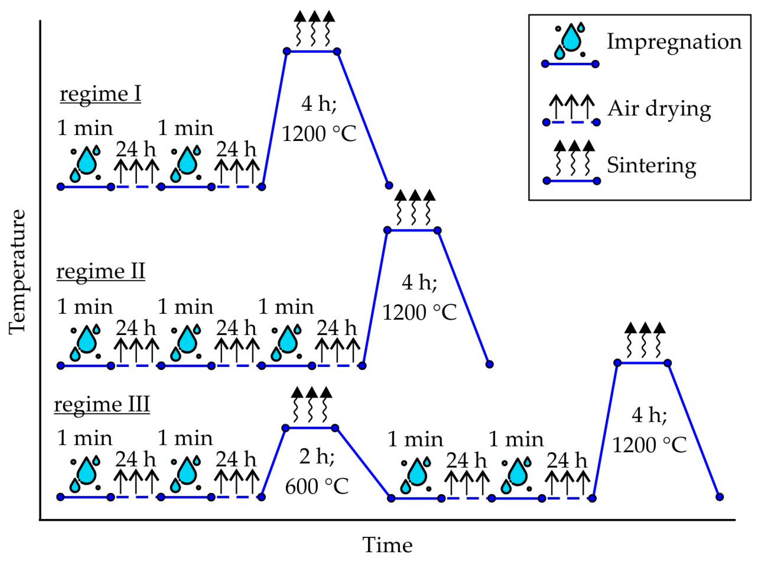
The specimens prepared by binder jetting were impregnated with colloidal silica binder, followed by air-drying and subsequent sintering according to the regimes presented in Figure 1. The UltraCast One+ (Technopark, Moscow, Russia) colloidal silica binder, which contains 25.5–27.5 wt.% SiO2 solid content and 8–10 nm particle size, was utilized for the impregnation process. Each impregnation step involved the immersion of the specimen for one minute in the colloidal silica binder, followed by air-drying at room temperature for a duration of 24 h subsequent to specimen removal. The sintering process was conducted in a resistance furnace, with a heating rate of 10–20 °C/min and cooling with the furnace. Regimes I and II were employed for the proppant specimens, while regimes I and III were utilized for the cenosphere specimens.
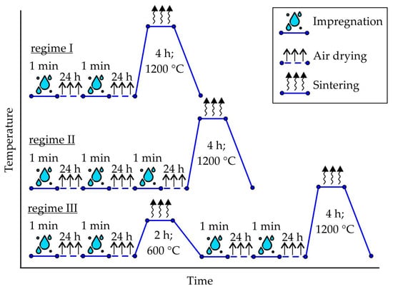
Figure 1.
The regimes of printed samples treatment made of proppant sand (regimes I and II) and cenosphere sand (regimes I and III).
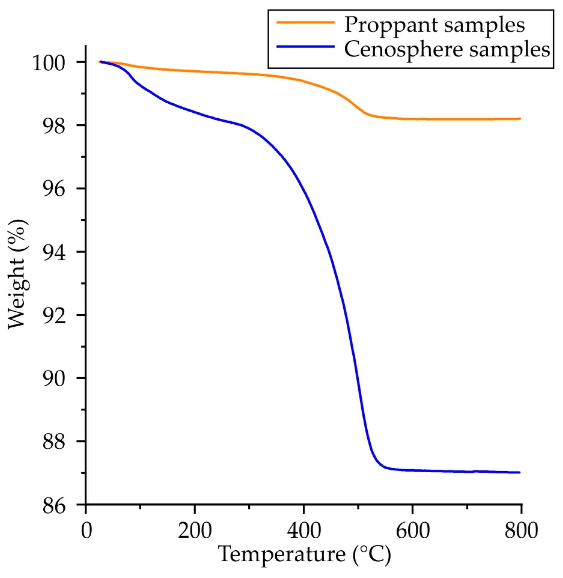
The thermogravimetric analysis (TGA) of the as-printed samples was conducted using the SDT Q600 analyzer (Simultaneous DSC-TGA Q Series, New Castle, DE, USA). The flow rate of the air employed as the carrier gas was 100 mL/min. The samples, with a mass ranging from 20 to 90 mg, were subjected to a heating process ranging from 20 to 800 °C in a corundum crucible at a heating rate of 10 °C/min. The weight change was analyzed with a sensitivity of 0.1 μg, and the weight and temperature measurement error was ±1% and ±0.5 °C, respectively.
The sand shape, size distribution and composition, as well as structure and elemental composition of the printed specimens were obtained with a scanning electron microscope (SEM) Vega SBH3 (Tescan, Brno, Czech Republic) coupled with an energy-dispersive X-ray spectrometer (X-act, Oxford, UK). ImageJ 1.52a (National Institutes of Health, Bethesda, MD, USA) was utilized for the shape and size parameters of the sands.
The X-ray diffractometry (XRD) technique was employed to ascertain the phase composition of the sands, green as-printed specimens and specimens after final impregnation and sintering procedures. The XRD analysis was obtained using a D8 ADVANCE diffractometer (Bruker, Billerica, MA, USA) under monochromatic Cu Kα radiation.
The 5966 universal testing machine (Instron, Norwood, MA, USA) was utilized to conduct three-point bending tests in accordance with the ASTM C1161-13 standard. The distance between the supports was set at 21 mm, and the loading rate was maintained at 1 mm/min.
Additionally, 163 × 10 × 10 mm specimens with a flat orientation were obtained for the purpose of determining the linear shrinkage. The length of green as-printed specimens (L0) and of the specimens after the final stage of the sintering (L) was measured using a caliper, with a measurement error of ±0.05 mm. Linear shrinkage ε was subsequently calculated using formula (1)
A volumetric analysis of impregnated and sintered proppant and cenosphere samples obtained via regimes II and III (see Figure 1) was performed on a nanoVoxel 1000 micro computed tomography (micro-CT) scanner (Sanying, China). A voxel size of 6 µm was achieved for the representative cylindrical samples with a diameter of 5 mm. Additionally, samples measuring 20 × 20 × 10 mm with a higher voxel size of 15 µm were analyzed. The acceleration voltage and current were set to 70 kV and 50 µA, respectively. The tomographic analysis was conducted with an exposure time of 2 s for a total of 1440 rotations. It is noteworthy that no averaging or binning techniques were employed during the analysis. The reconstruction process was facilitated by utilizing VoxelStudio software v. 2.5.1.25 (Sanying precision engineering, Sanying, China). The segmentation of the micro-CT data was performed using VG Studio Max v. 2024.3.0 (Volume Graphics, Heidelberg, Germany). Geometry assessment and fraction measurements were conducted using the built-in algorithms within VG software. The typical 2D slice of micro-CT results obtained for proppant sample obtained via regime II and segmentation results where proppant sand, pores and binder can be seen are presented in Figure 2.
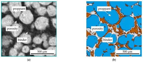
Figure 2.
The (a) 2D slice of micro-CT results for proppant sample obtained via regime II and (b) the segmentation results where the proppant sand, porosity and binder can be seen.
2.2. The Mold Preparing, Casting Procedure and Analysis of Castpart Properties
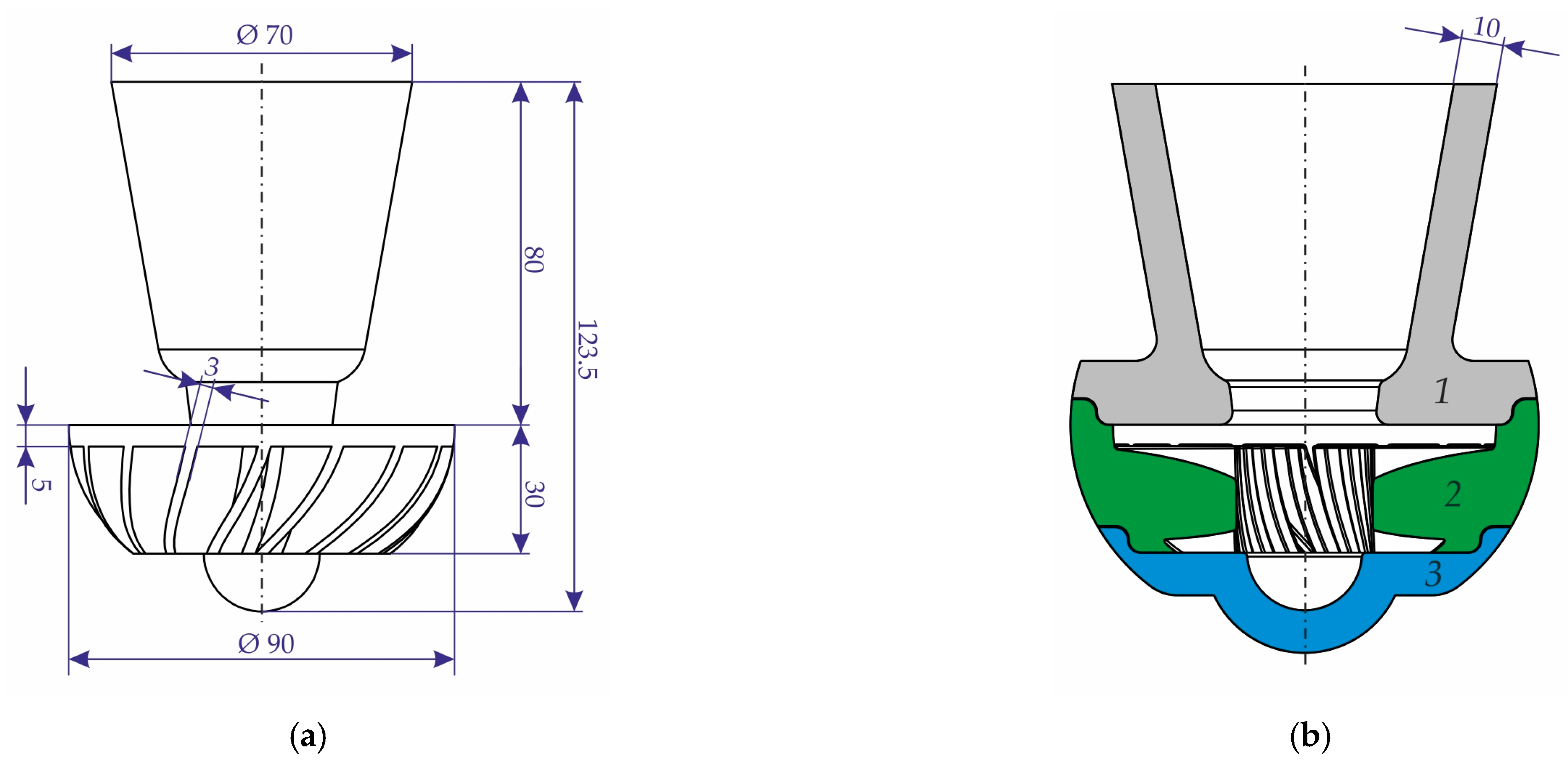
The impeller casting with gating system was constructed (see Figure 3). The shell mold, which consists of three parts with a 10 mm wall thickness, was manufactured. The part with number 1, which contains the cavity for the pouring cup and also acts as riser, was printed using cenosphere sand, and parts 2 and 3, which contain the cavity for casting, were printed using proppant sand. The printing regime was identical to that employed for the specimens (see Section 2.1). The impregnation and sintering regimes II and III (see Figure 1) were selected for the mold parts printed with proppant and cenosphere sands, respectively. Due to the increased size of the mold parts relative to the samples, the impregnation time was extended to 5 min.
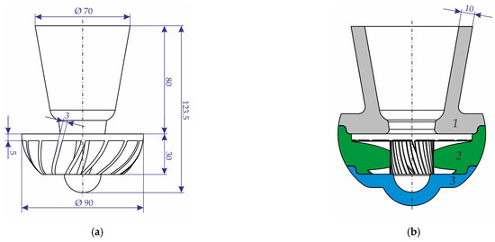
Figure 3.
The principal dimensions of the (a) impeller casting and gating system and (b) the scheme of the constructed mold.
Prior to the final sintering stage, the mold parts were placed in a steel container and filled from the outside with supporting bed of coarse corundum sand. The 4 kg raw nickel superalloy (wt.%) Ni-19%Cr-9%Fe-4.5%Mo-2.3%Mo-2.7%Ti-1.3%Al-0.05%C (VIAM, Moscow, Russia) melted by induction furnace (Reltec, Ekaterinburg, Russia) in a periclase crucible (Bakor, Moscow, Russia). The melting process was conducted in an air atmosphere, and a silicate glass slag was used to protect the melt. Subsequently, the molten alloy was poured into mold at an approximate temperature of 1500 °C. Prior to this, the mold with the corundum bed was preheated to 800 °C.
The surface roughness of the casting was measured using a VT6100 confocal microscope (Chotest Technology Inc., Zhiyuan, China). The surfaces in contact with the proppant and cenosphere mold parts were subjected to measurement. The Sz is defined as the sum of the largest peak height value and the largest pit depth value within the defined area of 1.2 × 1.2 mm2. The 3D point cloud data for Sz calculation were processed using XtremeVision Pro 3.0 software (Chotest Technology Inc., Zhiyuan, China).
The dimension accuracy of the casting was determined using laser scanning with a KScan Magic (ScanTech, Hangzhou, China) handheld 3D scanner. This device demonstrated a measurement accuracy of ±20 µm. The collected measurements were processed using Geomagic Design X 2019 software (3D Systems, Rock Hill, SC, USA), and a comparison of the obtained point clouds with the casting 3D model was performed in Geomagic Control X 2017 software (3D Systems, Rock Hill, SC, USA).
3. Results
3.1. The Proppant and Cenosphere Sand Morphology, Size Distribution and Elemental Composition
As demonstrated in Figure 4, the proppant and cenosphere sand SEM images indicate that the proppant sand displays a close-to-spherical morphology, exhibiting a mean roundness of 0.74. The cenosphere sand particles demonstrate a mean roundness value of 0.78, closely resembling the proppant, though with a slight deviation in shape, resembling near-perfect hollow spheres. This discrepancy can be attributed to the presence of satellites (small particles adhered to larger ones) and wrecked sand particles. The mean wall thickness of the cenosphere particles is approximately 4 µm. The shape of both sands are well suited for additive manufacturing.
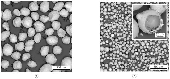
Figure 4.
The SEM images of the (a) proppant and (b) cenosphere sand.
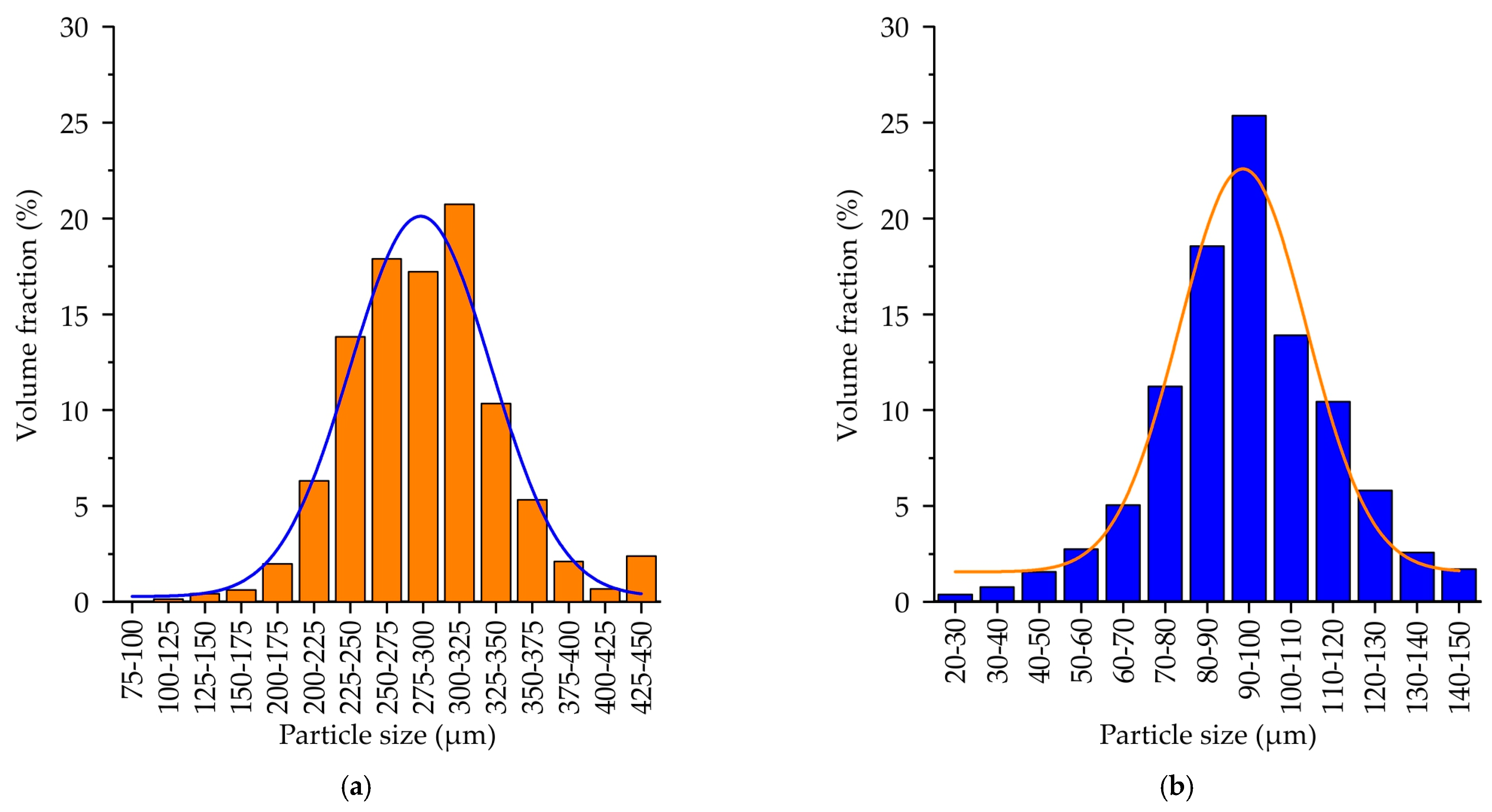
The grain size distribution for the proppant and the cenosphere sands is provided in Figure 5. For both sands, the particle size distribution is close to normal distribution. The mean size of the proppant sand particles and cenosphere sand particles was 254 ± 5 µm and 70 ± 3 µm, respectively. This significant difference in the sand particle size is attributed to the predetermined differences in printing modes employed for the proppant and the cenosphere sands. The printing regime utilized for the silica sand, which is conventionally employed in binder jetting for casting molds, is well-suited to the proppant sand due to the similarity in sand particle size and shape. However, the lower layer size and the higher curing agent and binder consumption are employed, given the higher surface-to-volume ratio of cenosphere sand. This is facilitated not only by the small size of the particles themselves but also by their hollow nature.
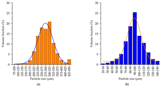
Figure 5.
The grain size distribution of (a) proppant sand, (b) cenosphere sand.
The elemental composition of the proppant and cenosphere sand particles, as determined via EDS analysis, is presented in Table 1. It is evident that the proppant sand is predominantly composed of Al and O, indicating that it is an aluminum oxide. Additionally, the presence of Si, Fe, Ti and Ca impurities is observed, though their proportion is insufficient to generate a substantial fraction of any novel phases. In contrast, the cenosphere sand exhibits a distinct composition, characterized by the prevalence of Si, Al and O as the primary elements. This suggests that the Si and Al-containing oxides are likely to be the predominant phases. The presence of other impurities, such as Ca, Ti, Fe, Mg, Na and K, is also observed, though their concentrations are negligible, with a maximum content of 0.3 at.% for each element.

Table 1.
EDS analysis results of the sands.
3.2. The TGA Analysis of the Samples Obtained via Binder Jetting Using Proppant and Cenosphere Sands
As demonstrated in Figure 6, the TGA outcomes for as-printed specimens manufactured using proppant and cenosphere sand exhibit analogous characteristic temperatures; the discrepancy lies solely in the proportion of weight loss. This disparity can be attributed to the diminished bulk density of the cenosphere relative to the proppant (0.4 vs. 1.9 g/cm3). The reduced bulk density of cenosphere sand, coupled with its hollow nature and comparatively smaller grain size, is another factor that necessitated the incorporation of higher proportions of curing agent and binder during the binder-jetting printing process to ensure the attainment of adequate mechanical properties. According to the TGA results, the weight loss for proppant and cenosphere as-printed samples was 1.8% and 13%, respectively. These values correspond to the weight fraction of the furan binder + curing agent in the samples.

Figure 6.
The weight loss of proppant and cenosphere-printed samples obtained via TGA.
The weight loss process for both the printed samples that incorporated proppant and cenosphere sands followed a similar trajectory, the cenosphere sand sample TGA curve serving as a representative example. According to the TGA data, the weight loss of the cenosphere sand as-printed sample commenced at a temperature close to 100 °C, attributable to the loss of water and residual monomer and oligomer volatilization [31,32]. The maximal weight loss rate was observed in the range of 300–500 °C, where the thermal destruction of furan binder was observed, and the destruction was fully ended when the sample temperature reached 600 °C. This temperature was, therefore, used as the sintering step in one of the sample preparation regimes. The hypothesis was that, under these conditions, the furan binder would burn out, freeing the pores, and that this would enable a second impregnation in colloidal silica binder to be applied prior to final sintering, with a view to increasing the samples’ strength. As will be demonstrated later, this intermediate heat treatment was shown to be effective for cenosphere-based samples.
3.3. The XRD Results for the Proppant and Cenosphere Sands and Samples Obtained via Binder Jetting and Impregnation with Colloidal Silica Binder
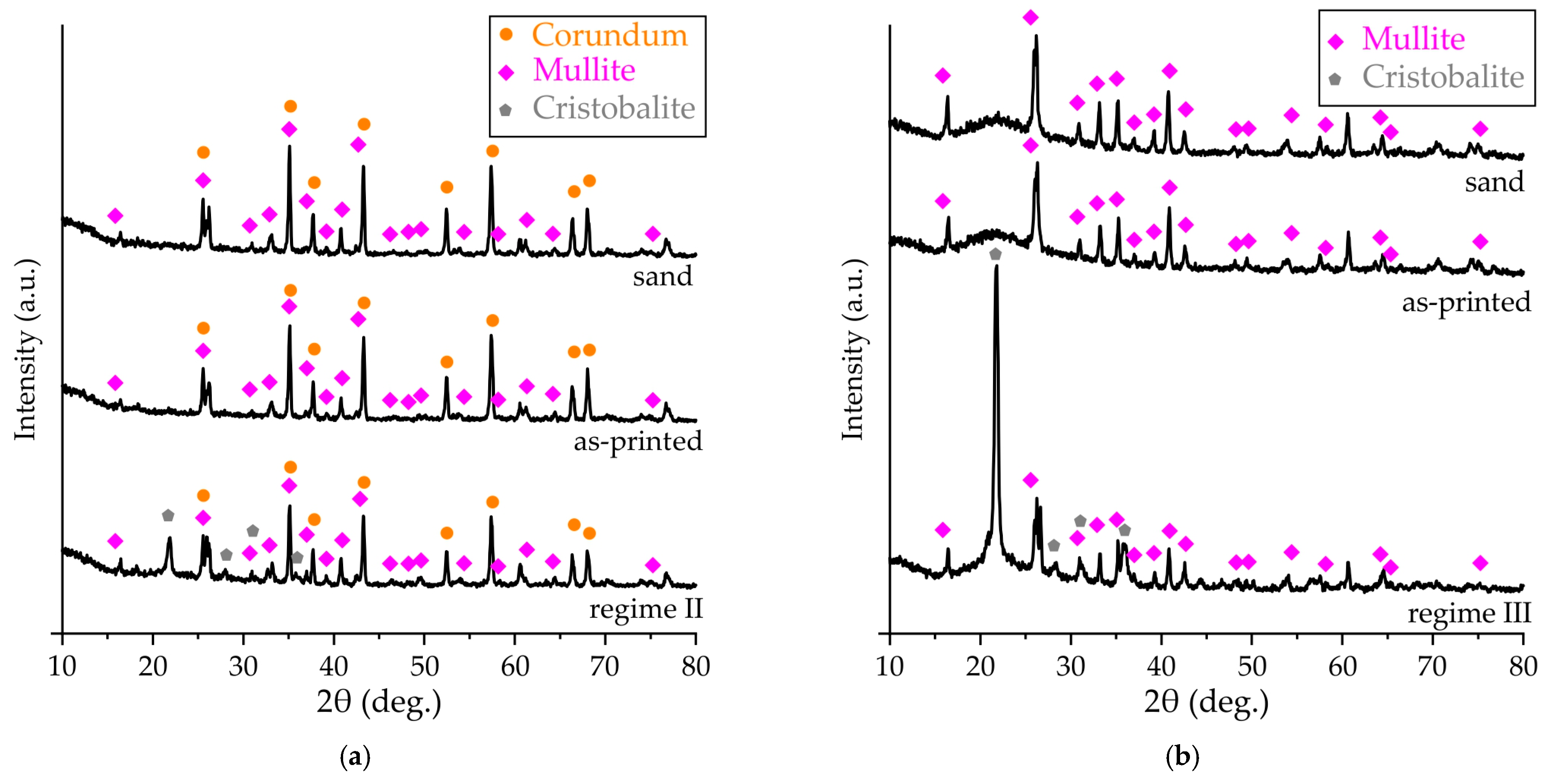
The XRD patterns of the proppant and cenosphere sands are presented in Figure 7. The two phases are clearly discernible in the structure of the proppant sand, namely corundum (α-Al2O3) [33,34] and mullite (3Al2O3·2SiO2) [33]. In accordance with the relative peak height and the EDS analysis results (Table 1), the fraction of the corundum was higher. The cenosphere sand exhibited a clear amorphous halo and multiple peaks, attributable to the presence of mullite. This observation aligns with the composition data obtained via EDS analysis, which revealed a significant presence of aluminum, silicon, and oxygen.
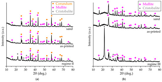
Figure 7.
The XRD patterns of (a) proppant and (b) cenosphere sand, as-printed and obtained via regimes II and III samples.
As demonstrated in Figure 7, the phase composition of the samples obtained via binder jetting is consistent with the composition of the sands utilized in their production. This consistency can be attributed to the use of an organic furan binder, which, despite its presence in significant fractions, does not manifest itself in XRD patterns.
The XRD pattern of the proppant printed sample after impregnation in colloidal silica binder and sintering procedures in accordance with regime II is presented in Figure 7a. It is evident that, in addition to corundum and mullite, some peaks of cristobalite (SiO2) [35] can be found. The colloidal silica binder is a water solution of colloidal SiO2, and its addition leads to the formation of cristobalite structures. The high temperature of sintering can also lead to the interaction of silicon and aluminum oxides, resulting in mullite formation. However, mullite is present in the sand and sample’s structure, and its relative intensity peaks remain largely unchanged.
The XRD pattern of the cenosphere sand as-printed sample after impregnation in colloidal silica binder and sintering procedures in accordance with regime III is presented in Figure 7b. The high intensity cristobalite peaks can be observed, indicating a higher fraction of the colloidal silica binder in the cenosphere samples in comparison with the samples obtained using proppant sand.
3.4. The Proppant and Cenosphere Sample Colloidal Silica Binder Impregnated and Sintered Structure
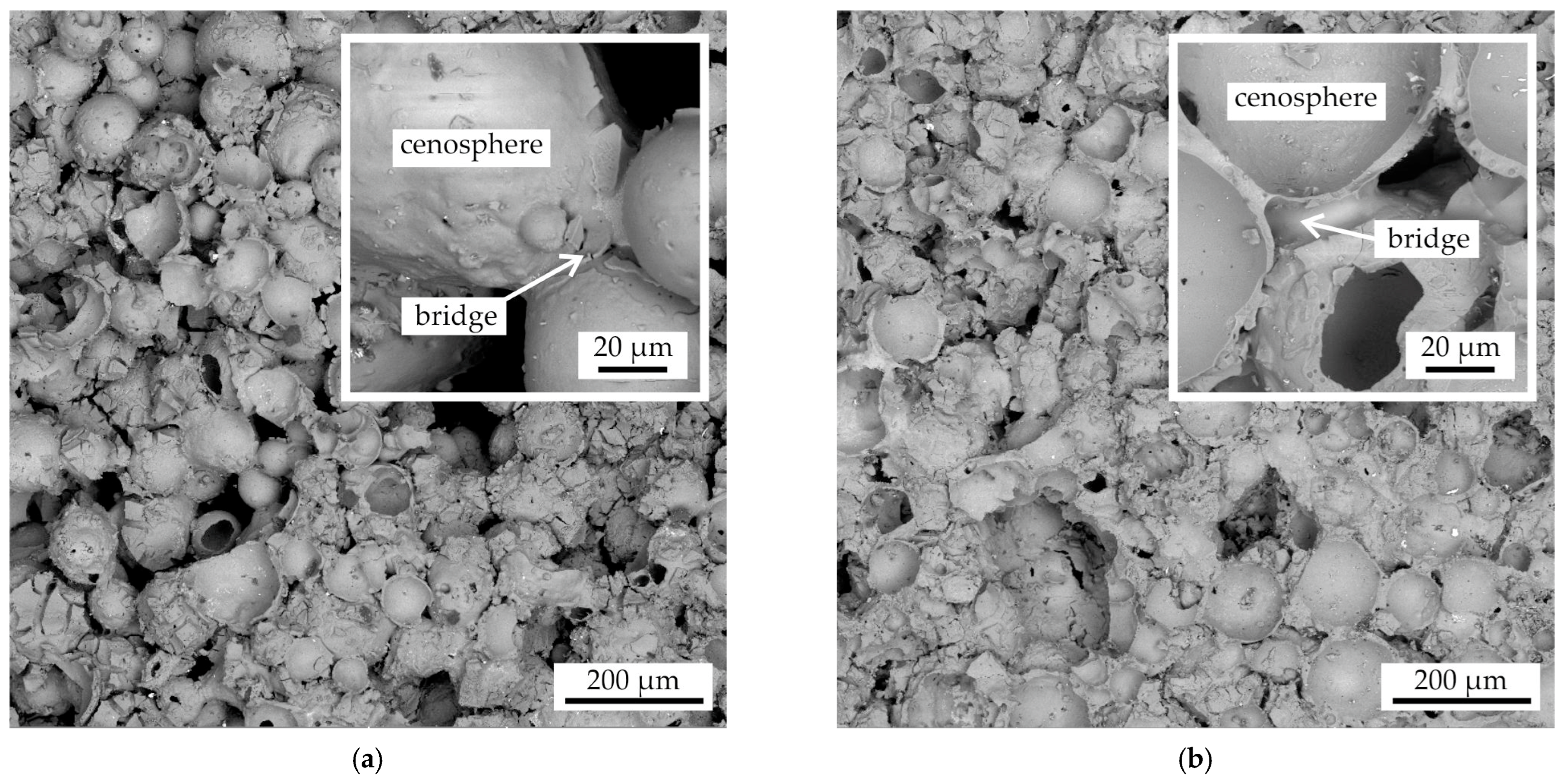
In Figure 8, the fracture microstructure of the proppant sample after impregnation and sintering in accordance with regimes I and II is presented. The number of impregnation procedures differs between these regimes (see Figure 1): two for regime I and three for regime II. In both cases, the proppant grains (light) and bridges of the binder (dark) can be seen. Despite the inherent limitations of fracture SEM images in quantitatively assessing the impact of impregnation steps on the volume fraction of the binder and the areas of bridges, it is evident that, irrespective of the number of impregnation steps, the fractures of the samples obtained by impregnation two times (regime I) and three times (regime II) appear similar.

Figure 8.
The fracture microstructure of the proppant samples after colloidal silica binder impregnation and sintering with the regimes: (a) regime I, (b) regime II.
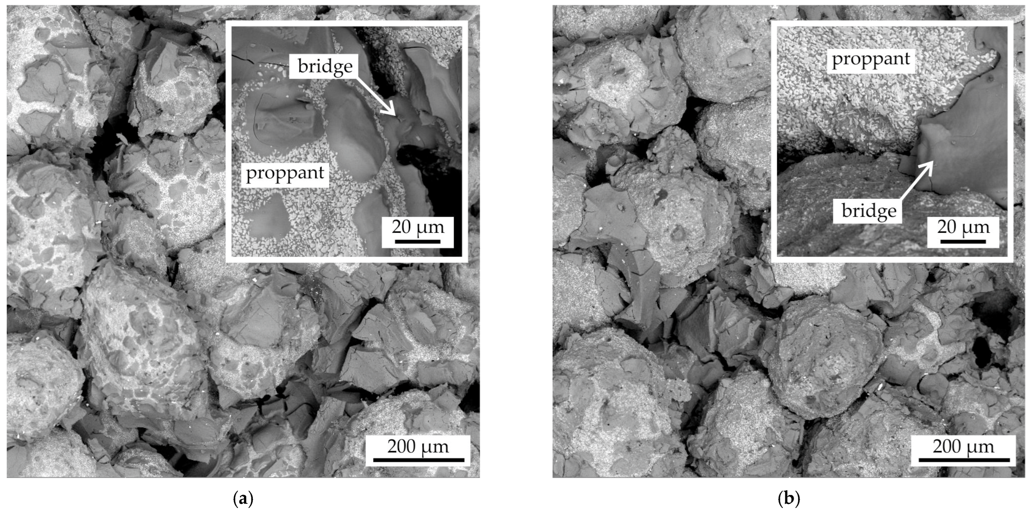
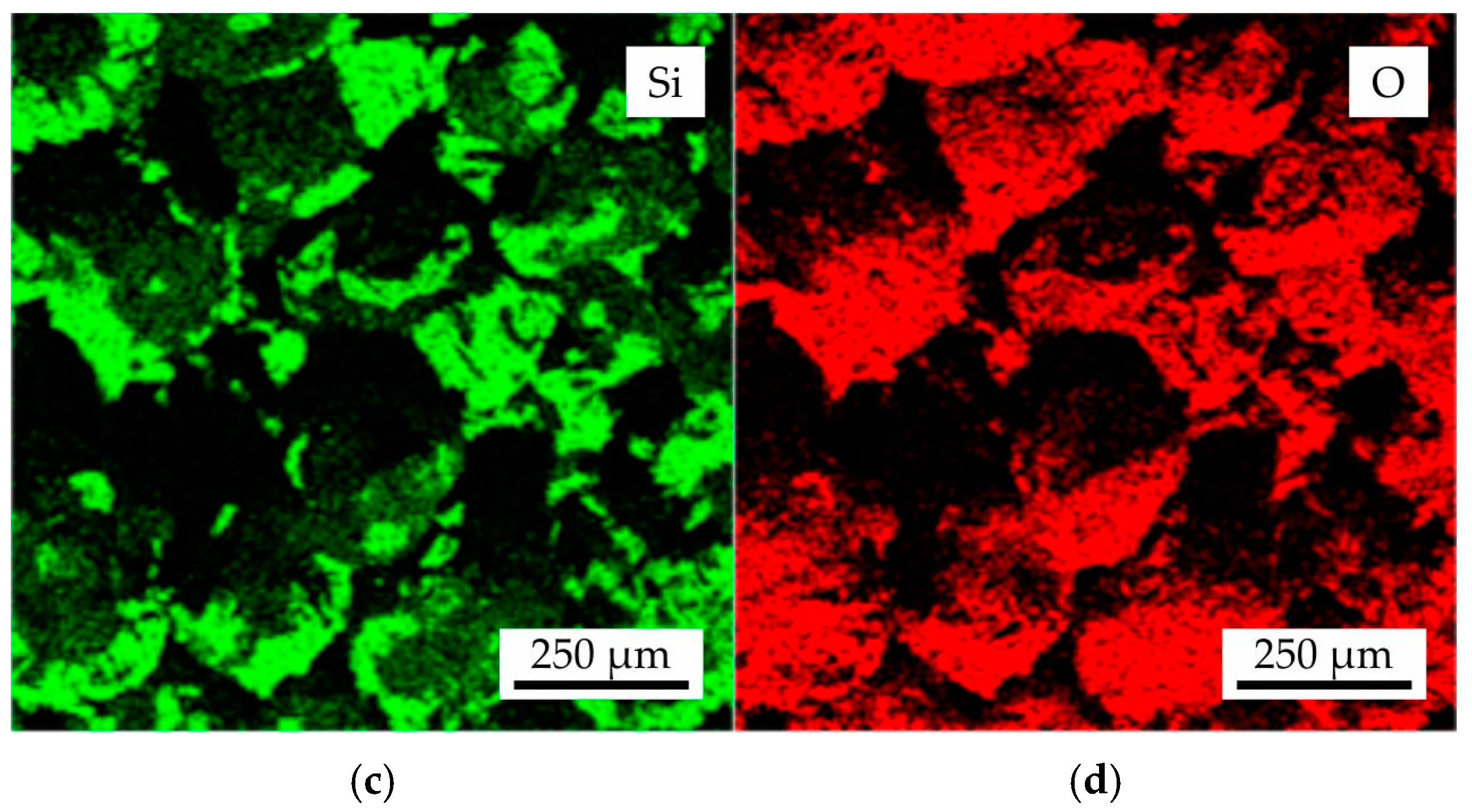
In Figure 9, the fracture microstructure and EDS maps of Al, Si, and O for the proppant sand as-printed sample following colloidal silica binder impregnation and sintering with the regime II were presented. The proppant grains were found to be composed of Al and O, as evidenced by the EDS maps. Additionally, the presence of Si was observed, though it was of low intensity. This observation aligns with the XRD results, which indicated the presence of corundum and mullite in the proppant sand grains within the obtained samples. Furthermore, the binder bridges were found to be composed of Si and O, suggesting a presence of cristobalite phase.
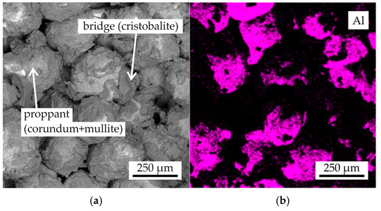
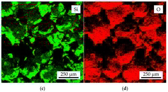
Figure 9.
The (a) fracture microstructure and EDS maps of (b) Al, (c) Si, and (d) O for the proppant sample after colloidal silica binder impregnation and sintering with regime II.
In Figure 10, the fracture microstructure of the cenosphere sand as-printed sample following impregnation and sintering according to regimes I and III is presented. The distinguishing factor between these two regimes (see Figure 1) is the incorporation of a pre-sintering step in regime III, which is employed to thermally degrade the furan binder and increase the pores volume for further impregnation. This is followed by two impregnation operations. The cenosphere sand grains are enveloped by the binder, forming bridges. It is evident that the destruction of the furan binder and the subsequent impregnation of the samples results in an increase in the fraction of binder bridges and a decrease in the fraction of voids (see Figure 10b).
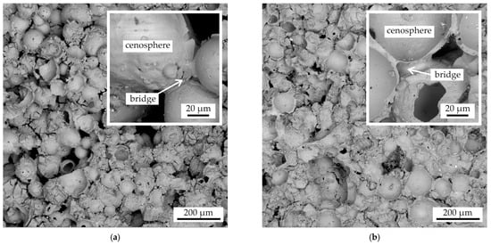
Figure 10.
The fracture microstructure of the cenosphere samples after colloidal silica binder impregnation and sintering with the regimes: (a) regime I, (b) regime III.
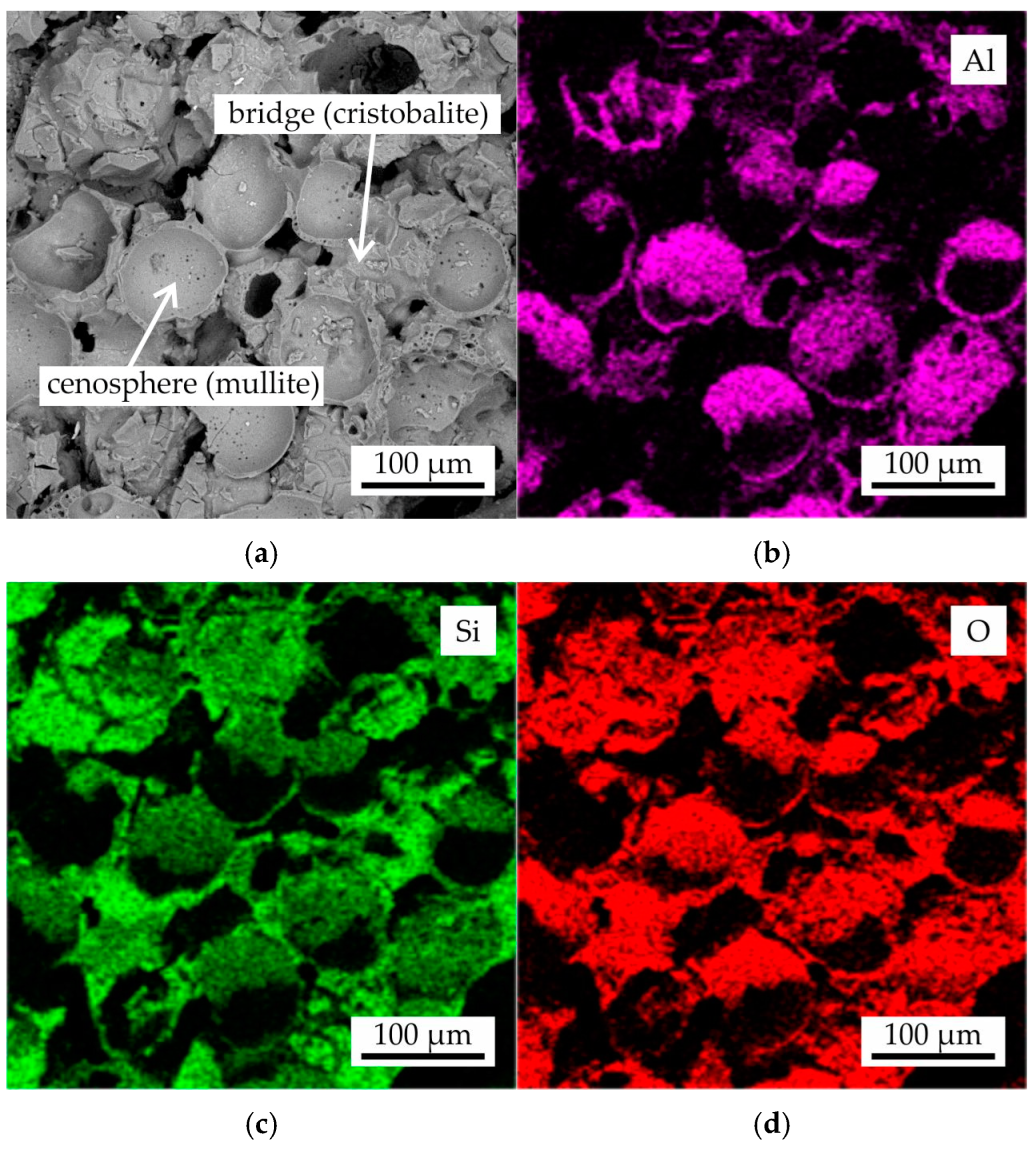
In Figure 11, the fracture microstructure and EDS maps of Al, Si, and O for the cenosphere sand as-printed sample following colloidal silica binder impregnation and sintering with regime III were presented. The analysis of the cenosphere grains revealed their composition to be Al, Si, and O, as evidenced by the EDS maps. This finding aligns with the XRD results, which indicated the presence of mullite in the cenosphere sand and cenosphere grains within the obtained samples. The binder bridges were found to be composed of Si and O, suggesting the presence of SiO2 (cristobalite phase).

Figure 11.
The (a) fracture microstructure and EDS maps of (b) Al, (c) Si, and (d) O for the cenosphere sample after colloidal silica binder impregnation and sintering with regime III.
3.5. The Micro-CT Results for As-Printed Proppant and Cenosphere Samples After Impregnation and Sintering
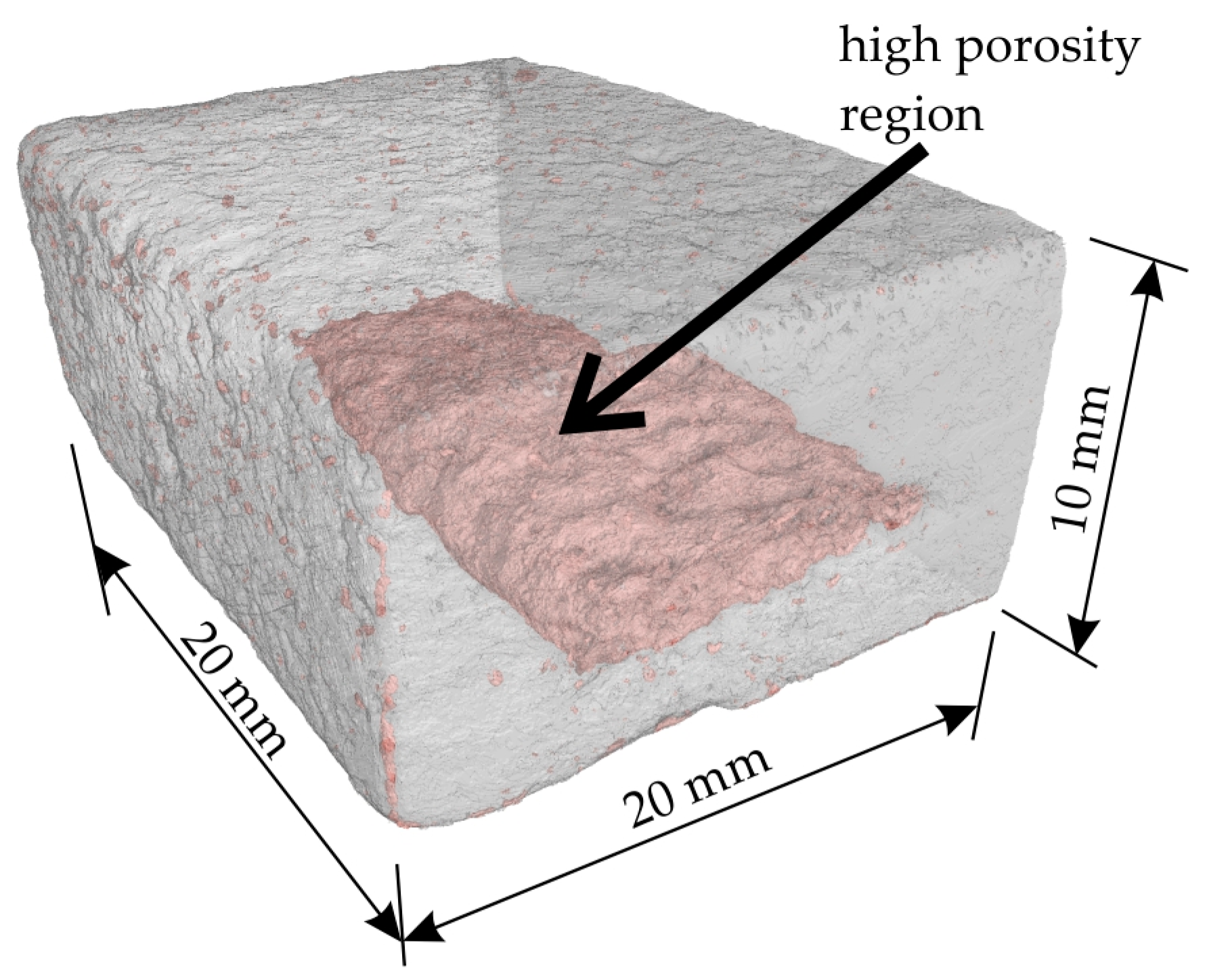
As illustrated in Figure 12, the micro-CT 3D reconstruction of the proppant sand-based sample obtained via regime II is presented. This reconstruction represents half of the bending test sample, with the higher porosity region highlighted in pink. The lack of binder in this area is postulated to be the cause of this region formation. Following the process of impregnation and removing the sample from the binder, a portion of the binder is observed to outflow from the sample due to gravitational forces. The effect of gravity on density heterogeneities within infiltrated regions has been previously observed in Ref. [15].
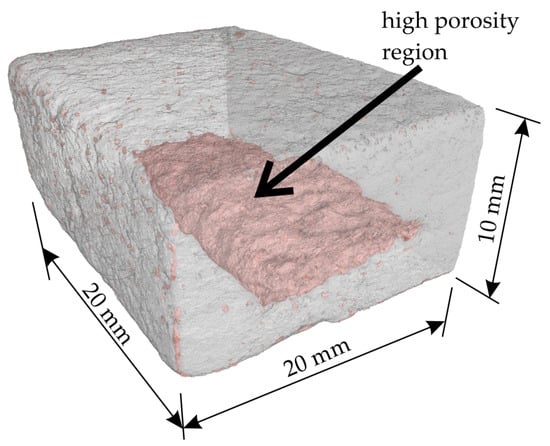
Figure 12.
The micro-CT 3D reconstruction of the proppant sand-based sample obtained via regime II. The area with relatively high porosity is shown by pink color.
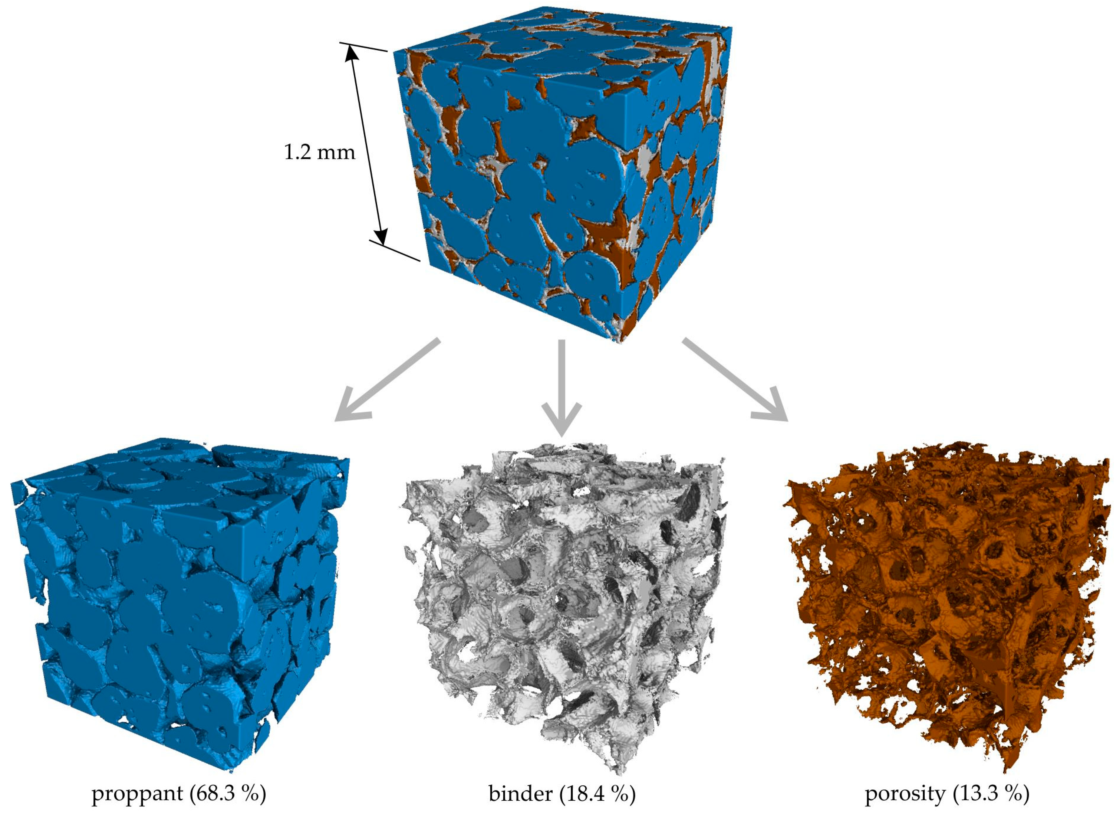
Figure 13 illustrates the micro-CT 3D reconstruction of a cubic segment with dimensions of 1.2 × 1.2 × 1.2 mm3 of the proppant sand-based sample obtained via regime II. Regions of interest corresponding to the proppant sand, binder, and porosity are delineated by blue, gray, and brown colors, respectively. The micro-CT data indicates that the proppant sand packing density is not high, occupying only 68.3% of the sample volume. This is attributable to the utilization of the binder-jetting 3D-printing technique. The binder and porosity are present between the grains of the proppant, and these regions look the same and have a close volume of 18.4% and 13.3%, respectively. The obtained data suggest that the impregnation technique provides a high porosity level, and the reason for that is the insufficient curing speed of the colloidal silica binder and its leakage.

Figure 13.
The micro-CT 3D reconstruction of the cubic 1.2 × 1.2 × 1.2 mm3 segment of proppant sand-based sample obtained via regime II. The areas of interest corresponding to proppant sand, binder, and porosity are shown by blue, gray, and brown colors, respectively. The volume percentage of each area calculated for all of the sample’s volume is also provided.
Figure 14 presents a 3D micro-CT reconstruction of a cubic segment measuring 1.2 × 1.2 × 1.2 mm3 of the cenosphere sand-based sample obtained via regime III. The regions of interest corresponding to the cenosphere sand + binder, and porosity are shown by gray and blue colors, respectively. It is evident that the cenosphere sand and binder form a relatively dense conglomerate. The porosity of the cenosphere sample was found to be 21.5%, which is notably higher than that of the proppant sample. However, the pores in the cenosphere sample exhibited a predominantly spherical shape, as depicted in Figure 14 This observation can be attributed to the nature of the cenosphere, which is a hollow sphere, and the binder’s inability to penetrate these spheres. Consequently, the mold fabricated from this material can exhibit both high strength and low thermal conductivity, which are essential properties for components that form the risers within the mold.
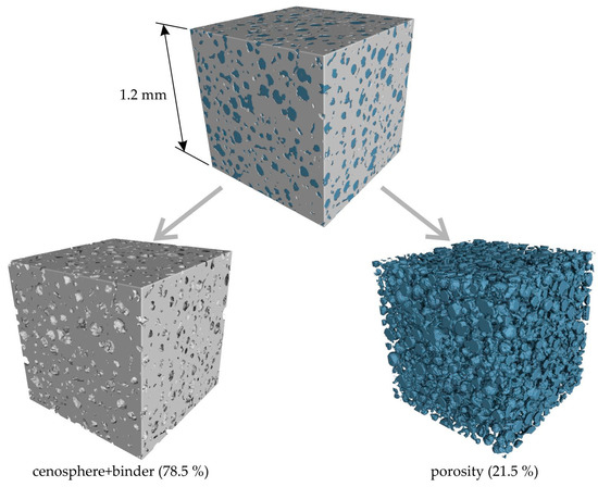
Figure 14.
The micro-CT 3D reconstruction of the cubic 1.2 × 1.2 × 1.2 mm3 segment of cenosphere sand-based sample obtained via regime III. The areas of interest corresponding to cenosphere sand + binder and porosity are shown by gray and blue colors, respectively. The volume percentage of each area calculated for all of the sample’s volume is also provided.
3.6. The Mechanical Properties of the As-Printed Proppant and Cenosphere Samples and Influence of Colloidal Silica Binder Impregnation and Sintering on the Mechanical Properties
It was observed that when the curing agent was initially mixed with cenosphere sand, the mechanical properties of the printed samples were suboptimal. In order to obtain satisfactory mechanical properties, it is recommended that firstly the curing agent is added, then held for 24 h, and finally the second portion of the curing agent is added prior to printing. The possible reason for this phenomenon is the interaction of the curing agent and potentially the binder with the cenosphere sand. It is, therefore, suggested that the preliminary addition of the curing agent be used to form a layer of reaction products, which would reduce the interaction intensity.
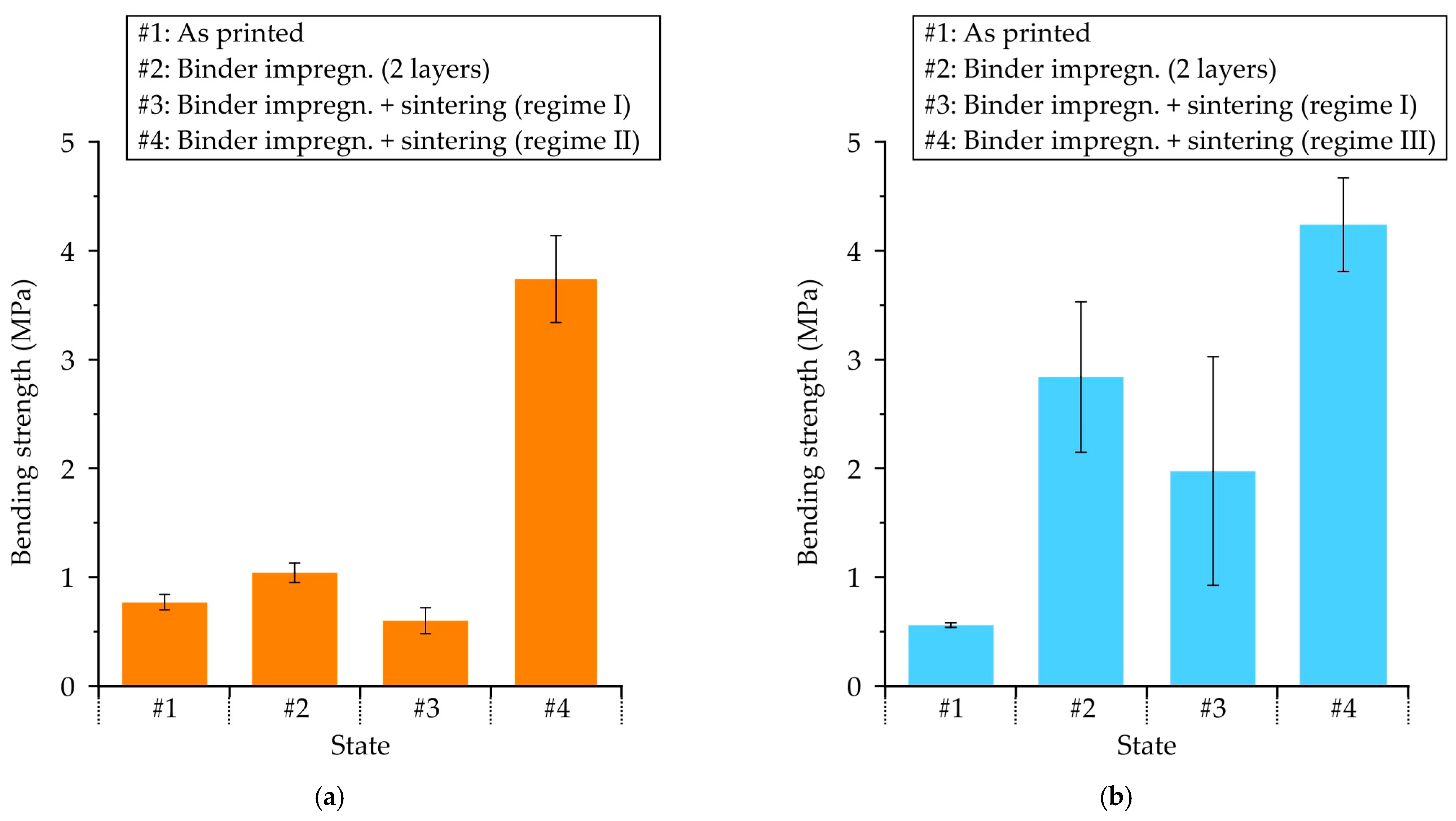
The bending strength of proppant sand-based samples in as-printed condition and after undergoing impregnation with a colloidal silica binder and sintering procedures is presented in Figure 15a. The results indicate that the as-printed sample possesses a bending strength of 0.77 MPa, which is sufficient for manipulations such as further impregnation. However, the samples underwent a two-step impregnation process in colloidal silica binder, resulting in a marginal increase in strength to 1.04 MPa. The subsequent sintering process, involving the burnout of the furan binder and the final hardening of the colloidal silica binder, resulted in a significant reduction in bending strength to 0.6 MPa. Consequently, the strength provided by regime I (Figure 1) is inadequate for the shell molds. Conversely, when the impregnation procedure was repeated three times (regime II), the final bending strength after sintering was 3.74 MPa, which is close to the bending strength of the shell mold samples obtained with colloidal silica binder (3–6 MPa) using conventional for investment casting procedure [36]. In a previous study [20], it was demonstrated that the bending strength of the molds is significantly influenced by the number of impregnation repetitions with an inorganic binder. It was found that a mere three impregnation repetitions were sufficient to achieve a bending strength comparable to that of the molds in this study.

Figure 15.
The mechanical properties of (a) proppant and (b) cenosphere sand-based samples in: as-printed condition and after colloidal silica binder impregnation and sintering procedures.
In Figure 15b the bending strength of cenosphere sand-based samples in their as-printed state and after undergoing the colloidal silica binder impregnation and sintering procedures is presented. The as-printed sample exhibits a bending strength of 0.56 MPa; however, when the impregnation procedure in colloidal silica binder is repeated twice, the strength is increased fivefold, reaching 2.84 MPa. This enhancement in strength can be attributed to the increased surface area available for binding. However, the strength decreased to 1.98 MPa after the sintering process (regime I), which was insufficient for the shell molds. Nevertheless, the application of regime III resulted in a substantial increase in bending strength to 4.24 MPa, indicating a significant enhancement in the effectiveness of the impregnation process. In certain instances, the pre-sintering operations were employed to generate pores subsequent to the burnout of the binder utilized for 3D printing. The utilization of binder for filling prior to final sintering can be streamlined, which has the potential to enhance strength [37,38]. The regime III process (see Figure 1) involves a sequence of steps, including the initial two impregnations in colloidal silica binder, and furan binder burnout followed by next two-step impregnation in colloidal silica binder prior to the final sintering. Analysis of the fracture structure (Figure 10) revealed that regime III application led to an augmentation in the proportion of binder bridges and a reduction in the fraction of voids. Consequently, regime III was recommended for cenosphere sand-based samples, as it was demonstrated to provide mechanical properties that align with the recommended range for shell molds [36].
3.7. The Linear Shrinkage of As-Printed Proppant and Cenosphere Samples After Impregnation and Sintering
In accordance with the long sample length measurements, the linear shrinkage of proppant sand-based samples obtained via regime II is found to be minimal (0.5 ± 0.1%). Conversely, the higher shrinkage of 1.8 ± 0.2% is measured for cenosphere sand-based samples obtained via regime III. This outcome is notable as it falls below the range of values observed for other mold and core samples produced via binder-jetting and UV light photopolymerization 3D-printing techniques [8,17,18,22,26,27], and closely resembles the most optimal results (1–3%) reported in the extant literature [9,14]. The disparity in linear shrinkage between the proppant and cenosphere samples can be attributed to the size of the initial sand particles, with proppant sand particles being larger than cenosphere sand particles. Consequently, during sintering, proppant sand particles exhibit a lower degree of shrinkage. It is well established that powders with smaller particles yield ceramics with a very high linear shrinkage [13].
3.8. The Mold Production and Casting Results
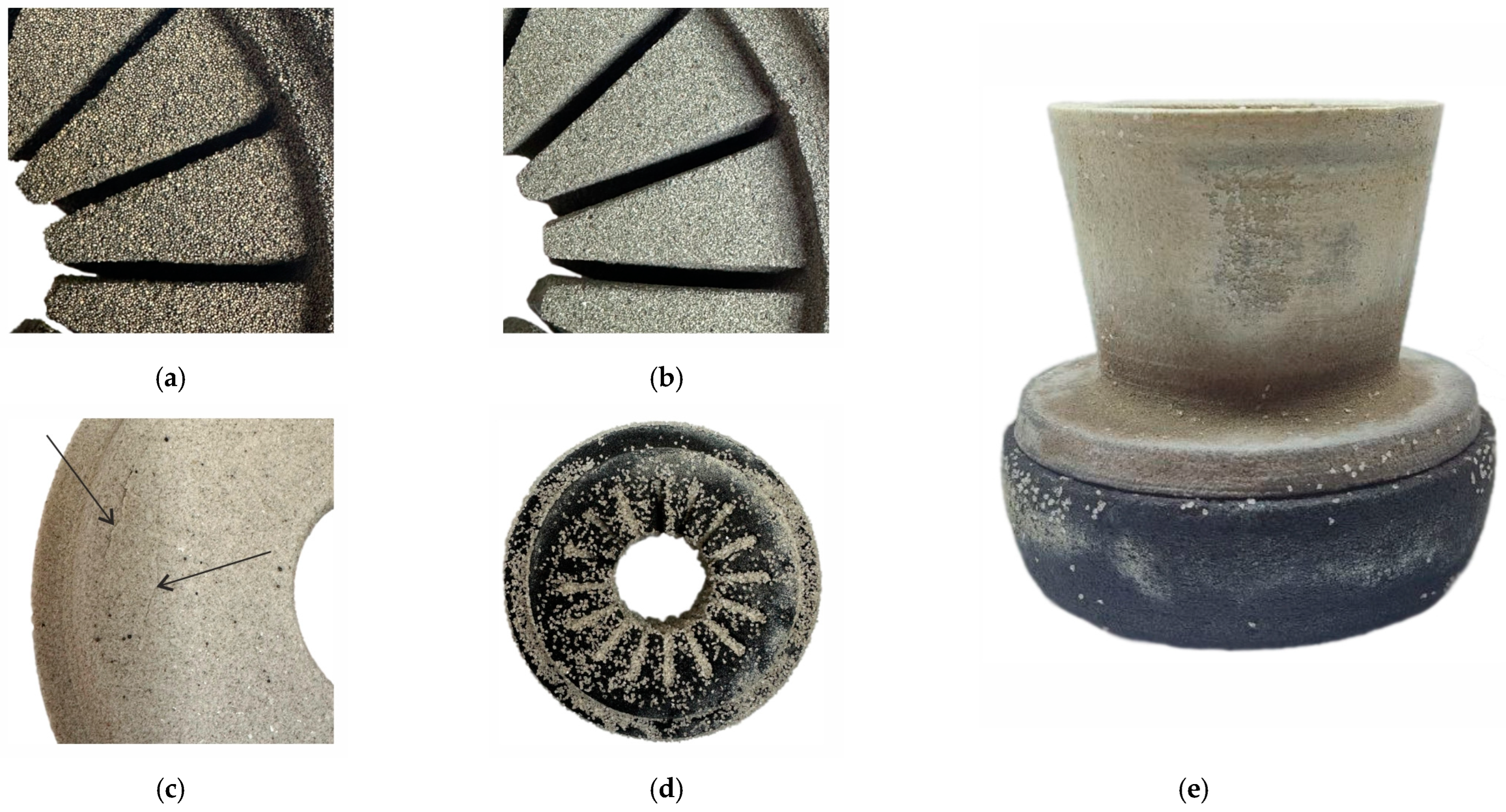
As demonstrated in Figure 16a,b, the mold components fabricated via binder jetting demonstrate a marked enhancement in surface quality when utilizing cenosphere sand compared to proppant sand. This enhancement can be attributed to the finer size of cenosphere sand particles, as illustrated in Figure 5.

Figure 16.
The as-printed mold parts made using (a) proppant sand and (b) cenosphere sand. (c) The cenosphere sand mold part after intermediate heat treatment at 600 °C (the cracks are shown by arrows). (d) The proppant sand mold part after final sintering at 1200 °C. (e) The final mold assembly with proppant sand parts made of regime II and cenosphere sand part made of regime III.
During the fabrication of the mold parts, a number of defects were identified. The pre-sintering of the cenosphere sand mold part at 600 °C resulted in the formation of cracks, as indicated by the arrows in Figure 16c. Subsequent analysis determined that the upper surfaces of the molds exhibited diminished strength following intermediate sintering. This phenomenon was attributed to the outflow of the colloidal silica binder from the mold part following the impregnation process, a consequence of the influence of gravity and the low curing speed of the binder. It is, therefore, recommended that the position of the mold part be altered after each impregnation and drying stage to ensure optimal results.
In Figure 16d, the proppant sand mold part following the final sintering process at 1200 °C was presented. During the final sintering stage, the coarse corundum sand was utilized as the supporting bed material to prevent the deformation of the mold parts. It is evident that a portion of the corundum particles had undergone agglomeration with the mold part, which significantly complicates the process of cleaning the mold. One potential solution to this issue involves a two-pronged approach: a reduction in sintering temperature and an augmentation in the size of the support bed particles.
The final mold assembly is shown in Figure 16e. It was observed that the upper part of the mold made with cenosphere sand exhibits poor contact with the part of the mold made with proppant sand. As previously established, the linear shrinkage for the cenosphere sand-based samples is nearly quadruple that of the proppant sand-based samples (see Section 3.7). This has led to the presence of a substantial gap at the interface of the mold parts and the formation of a flash defect on the casting. To address this issue, it is imperative to utilize sands of comparable particle sizes, as this will ensure comparable values of linear shrinkage during sintering. Additionally, reducing the sintering temperature can contribute to a reduction in the linear shrinkage of the mold [9,11,12,13,28].
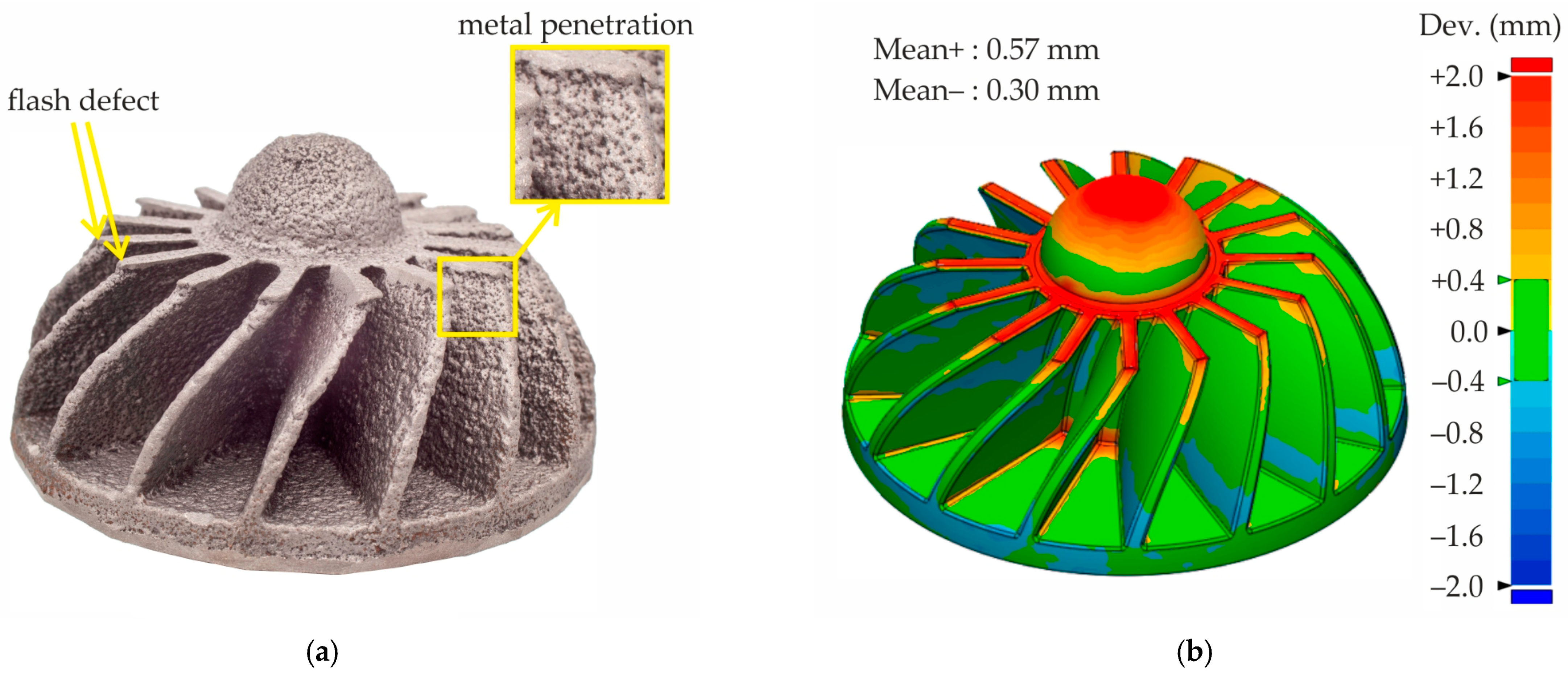
The nickel superalloy castings produced using the mold fabricated with proppant and cenosphere sands via binder jetting and colloidal silica binder impregnation and further sintering exhibit several defects (see Figure 17a). The impeller casting reveals a flash defect, characterized by a thin excess layer of metal along the parting line. This phenomenon can be attributed to inadequate fitting of mold parts against each other due its different linear shrinkage during sintering. Additionally, the penetration of metal deep into the mold is evident. This phenomenon is further elucidated in the insert of Figure 17a, which also highlights the presence of proppant sand grains within the casting.
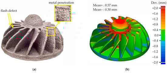
Figure 17.
(a) The nickel superalloy casting obtained using the mold made with proppant and cenosphere parts fabricated via binder jetting and colloidal silica impregnation and (b) the dimensional deviation map for the nickel superalloy casting.
In accordance with established casting practices, the initial casting CAD model was scaled to compensate for both the alloy and the mold shrinkage to ensure adequate dimensional accuracy. In this study, no scaling of the casting or mold CAD model was conducted during mold printing to ascertain the value of linear shrinkage. The minimal deviation between the CAD model and the obtained casting is observed when the casting CAD model is scaled to a value of 1.5%. Therefore, in Figure 17b, the dimensional deviation map is provided for the CAD model of the casting, which is scaled to 1.5% in comparison with the cloud of points of the casting obtained by 3D scanning. As can be seen, the dimensional deviations for most of the casting area do not exceed 2 mm. However, deviations greater than 2 mm are observed in the parting line of the casting, where a flash defect is present. Statistical analysis of dimensional deviations indicates that the mean positive deviations of +0.57 mm are twice as high as the negative deviations of –0.30 mm. The presence of a flash defect is identified as the primary cause of this phenomenon.
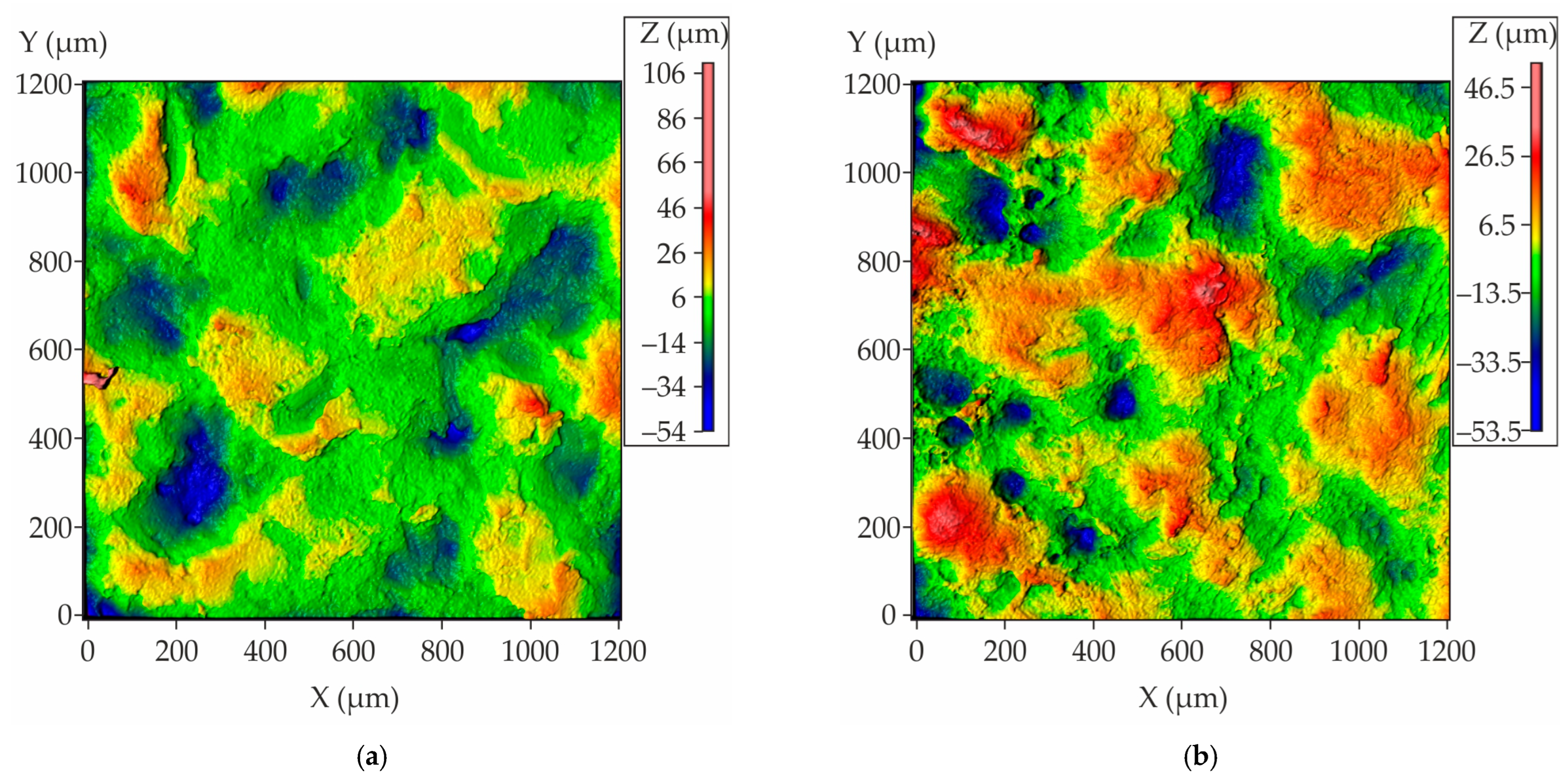
As illustrated in Figure 18, the results of the roughness measurement for the obtained casting are presented, demonstrating that the majority of the analyzed area exhibits uniform and low roughness for the casting regions that interface with both proppant and cenosphere mold parts. Concurrently, there is a discernible presence of minor areas characterized by the observation of peaks and valleys. As is customary for castings, the Rz, which is defined as the average distance between the highest peaks and lowest valleys on the surface profile, corresponds to the analogous value Sz for the area. The Sz measurements for the casting areas that were in contact with the proppant and cenosphere mold parts are 152 ± 13 µm and 115 ± 8 µm, respectively. These values are notably higher than those obtained for conventional casting techniques. Consequently, the presented mold-making method can be recommended for castings with minimal roughness requirements.
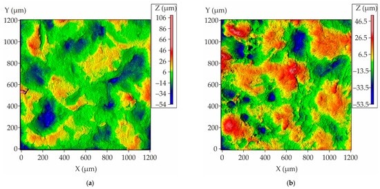
Figure 18.
The surface roughness plots of nickel superalloy casting obtained using the mold made with proppant and cenosphere parts fabricated via binder jetting and colloidal silica impregnation where (a) the segment of the casting that contact with the mold part made of proppant sand and (b) the segment of the casting that contact with the mold part made of cenosphere sand.
Binder-jetting technology has been utilized in the fabrication of 3D-printed molds, which have subsequently been immersed in a colloidal silica binder and sintered. This method has been demonstrating sufficient dimensional accuracy for nickel superalloy casting. However, a number of issues were identified during the course of this study. Firstly, inadequate casting surface quality was observed for both the areas that contact with proppant and cenosphere sand mold parts. It is imperative to note that the reduction in sand size should result in a decrease in roughness, particularly for proppant sand. Also to decrease the casting surface roughness, it is recommended that the mold surface be coated.
4. Conclusions
The structure and properties of proppant and cenosphere sand-based mold materials obtained via furan binder jetting and impregnation with colloidal silica binder were investigated and a nickel superalloy casting was obtained and analyzed. The following results were obtained:
- i.
- The proppant and cenosphere sands have a mean grain size of 254 and 70 µm, respectively, and both are well suited for additive manufacturing via the binder-jetting technique because of the shape close to spherical. The proppant sand is a mixture of corundum and mullite, while cenosphere sand is primarily mullite.
- ii.
- For proppant sand printing via binder jetting, the conventional quantities of furan binder and curing agent required for silica sand printing are employed. However, for cenosphere sand, the necessity arises to employ reduced layer thickness and elevated consumption of furan binder and curing agent to attain minimal required green strength greater than 0.5 MPa.
- iii.
- It was established that, following impregnation due to gravitational action, the colloidal silica binder flows out from the printed mold part, thereby decreasing the strength and promoting crack formation in the mold parts.
- iv.
- The structure of the proppant-based mold material after three times impregnation in colloidal silica binder and sintering consists of proppant sand grains (68%) with cristobalite binder bridges (18%) and porosity (13%). The cenosphere-based mold material obtained via a regime of two times impregnation, pre-sintering, two times additional impregnation, and final sintering exhibits a higher porosity of 21.5%. However, these pores are spherical in shape and located within the hollow cenosphere, thereby exerting no influence on the mold material’s strength.
- v.
- To achieve a bending strength of approximately 4 MPa, which is essential for the shell mold components, a minimum of three impregnations in colloidal silica binder is required for the proppant sand mold. In the case of cenosphere sand molds, after impregnation, a pre-sintering operation is necessary prior to final sintering. This is due to the high content of furan binder, which leads to a substantial reduction in strength following the burnout of furan binder.
- vi.
- While adequate dimensional accuracy was achieved for the nickel superalloy impeller casting, the surface quality is significantly lower than that of conventional casting techniques. The surface roughness (Sz) values for casting areas in contact with the proppant and cenosphere mold parts were 152 and 115 µm, respectively.
The present study has revealed that the utilization of a furan binder-jetting 3D-printing technique, in conjunction with impregnation in colloidal silica binder, is a promising methodology for producing molds for casting high-melting-temperature alloys.
Author Contributions
Conceptualization, V.E.B.; methodology, A.V.K.; software, K.A.D.; validation, K.A.D.; formal analysis, A.A.R.; investigation, K.A.D., A.A.R., Y.V.T., S.V.C. and A.I.B.; resources, A.S.A. and E.Y.S.; data curation, A.V.K.; writing—original draft preparation, V.E.B.; writing—review and editing, A.V.K.; visualization, A.S.A. and K.A.D.; supervision, A.V.K. and V.D.B.; project administration, A.V.K., V.D.B. and E.Y.S.; funding acquisition, V.D.B. and E.Y.S. All authors have read and agreed to the published version of the manuscript.
Funding
This research received financial support from the Ministry of Science and Higher Education in the Russian Federation (Agreement No. 075-11-2022-023 from 6 April 2022) under the program “Scientific and Technological Development of the Russian Federation” according to governmental decree N 218 dated 9 April 2010.
Institutional Review Board Statement
This study did not involve humans or animals.
Informed Consent Statement
This study did not involve humans.
Data Availability Statement
The data presented in this study are available upon request from the corresponding author.
Conflicts of Interest
Author Eugene Yu. Shchedrin was employed by the company Public Joint Stock Company UEC “Kuznetsov” Author Alexey S. Anishchenko was employed by the company LLC Polimet. The remaining authors declare that the research was conducted in the absence of any commercial or financial relationships that could be construed as a potential conflict of interest.
References
- Sivarupan, T.; Balasubramani, N.; Saxena, P.; Nagarajan, D.; El Mansori, M.; Salonitis, K.; Jolly, M.; Dargusch, M.S. A Review on the Progress and Challenges of Binder Jet 3D Printing of Sand Moulds for Advanced Casting. Addit. Manuf. 2021, 40, 101889. [Google Scholar] [CrossRef]
- Sivarupan, T.; El Mansori, M.; Coniglio, N.; Dargusch, M. Effect of Process Parameters on Flexure Strength and Gas Permeability of 3D Printed Sand Molds. J. Manuf. Process. 2020, 54, 420–437. [Google Scholar] [CrossRef]
- Walker, J.; Harris, E.; Lynagh, C.; Beck, A.; Lonardo, R.; Vuksanovich, B.; Thiel, J.; Rogers, K.; Conner, B.; MacDonald, E. 3D Printed Smart Molds for Sand Casting. Inter. Metalcast. 2018, 12, 785–796. [Google Scholar] [CrossRef]
- Dana, H.R.; El Mansori, M. Mechanical Characterisation of Anisotropic Silica Sand/Furan Resin Compound Induced by Binder Jet 3D Additive Manufacturing Technology. Ceram. Int. 2020, 46, 17867–17880. [Google Scholar] [CrossRef]
- Guo, N.; Leu, M.C. Additive Manufacturing: Technology, Applications and Research Needs. Front. Mech. Eng. 2013, 8, 215–243. [Google Scholar] [CrossRef]
- Chen, F.; Zhu, H.; Wu, J.-M.; Chen, S.; Cheng, L.-J.; Shi, Y.-S.; Mo, Y.-C.; Li, C.-H.; Xiao, J. Preparation and Biological Evaluation of ZrO2 All-Ceramic Teeth by DLP Technology. Ceram. Int. 2020, 46, 11268–11274. [Google Scholar] [CrossRef]
- Guo, J.; Zeng, Y.; Li, P.; Chen, J. Fine Lattice Structural Titanium Dioxide Ceramic Produced by DLP 3D Printing. Ceram. Int. 2019, 45, 23007–23012. [Google Scholar] [CrossRef]
- Zeng, Y.; Chen, X.; Sun, L.; Yao, H.; Chen, J. Effect of Different Sintering Additives Type on Vat Photopolymerization 3D Printing of Al2O3 Ceramics. J. Manuf. Process. 2022, 83, 414–426. [Google Scholar] [CrossRef]
- Pan, Y.; Li, H.; Liu, Y.; Liu, Y.; Hu, K.; Wang, N.; Lu, Z.; Liang, J.; He, S. Effect of Holding Time During Sintering on Microstructure and Properties of 3D Printed Alumina Ceramics. Front. Mater. 2020, 7, 54. [Google Scholar] [CrossRef]
- Basar, O.; Veliyath, V.P.; Tarak, F.; Sabet, E. A Systematic Study on Impact of Binder Formulation on Green Body Strength of Vat-Photopolymerisation 3D Printed Silica Ceramics Used in Investment Casting. Polymers 2023, 15, 3141. [Google Scholar] [CrossRef]
- Corcione, C.E.; Greco, A.; Montagna, F.; Licciulli, A.; Maffezzoli, A. Silica Moulds Built by Stereolithography. J. Mater. Sci. 2005, 40, 4899–4904. [Google Scholar] [CrossRef]
- Wang, L.; Liu, X.; Wang, G.; Tang, W.; Li, S.; Duan, W.; Dou, R. Partially Stabilized Zirconia Moulds Fabricated by Stereolithographic Additive Manufacturing via Digital Light Processing. Mater. Sci. Eng. A 2020, 770, 138537. [Google Scholar] [CrossRef]
- Huang, S.; Ye, C.; Zhao, H.; Fan, Z. Additive Manufacturing of Thin Alumina Ceramic Cores Using Binder-Jetting. Addit. Manuf. 2019, 29, 100802. [Google Scholar] [CrossRef]
- Sviridova, I.; Holling, H.; Tang, W.; Küll, A.; Terán, C.M. Production of Ceramic Investment Casting Shells Using Lithography-Based Ceramic Manufacturing and Binder Jetting Technology. JMMP 2024, 8, 162. [Google Scholar] [CrossRef]
- Chen, Q.; Juste, E.; Lasgorceix, M.; Lefebvre, G.; Tenailleau, C.; Duployer, B.; Grossin, D.; Petit, F.; Leriche, A. Post-Infiltration to Improve the Density of Binder Jetting Ceramic Parts. J. Eur. Ceram. Soc. 2022, 42, 7134–7148. [Google Scholar] [CrossRef]
- Peng, L.; Jiang, W.; Yang, L.; Chen, Z.; Li, G.; Guan, F.; Fan, Z. Effect of Silica Sol on Performance and Surface Precision of Alumina Ceramic Shell Prepared by Binder Jetting. Ceram. Int. 2022, 48, 24372–24382. [Google Scholar] [CrossRef]
- Li, H.; Elsayed, H.; Colombo, P. Enhanced Mechanical Properties of 3D Printed Alumina Ceramics by Using Sintering Aids. Ceram. Int. 2023, 49, 24960–24971. [Google Scholar] [CrossRef]
- Li, F.; Ji, X.; Wu, Z.; Qi, C.; Lai, J.; Xian, Q.; Sun, B. Digital Light Processing 3D Printing of Ceramic Shell for Precision Casting. Mater. Lett. 2020, 276, 128037. [Google Scholar] [CrossRef]
- Curodeau, A.; Sachs, E.; Caldarise, S. Design and Fabrication of Cast Orthopedic Implants with Freeform Surface Textures from 3-D Printed Ceramic Shell. J. Biomed. Mater. Res. 2000, 53, 525–535. [Google Scholar] [CrossRef]
- Kim, E.-H.; Choi, H.-H.; Jung, Y.-G. Fabrication of a Ceramic Core for an Impeller Blade Using a 3D Printing Technique and Inorganic Binder. J. Manuf. Process. 2020, 53, 43–47. [Google Scholar] [CrossRef]
- Rodríguez-González, P.; Zapico, P.; Robles-Valero, P.E.; Barreiro, J. Novel Post-Processing Procedure to Enhance Casting Molds Manufactured by Binder Jetting AM. Addit. Manuf. 2022, 59, 103142. [Google Scholar] [CrossRef]
- Bae, C.-J.; Halloran, J.W. Integrally Cored Ceramic Mold Fabricated by Ceramic Stereolithography: Ceramic Mold Fabricated by Ceramic Stereolithography. Int. J. Appl. Ceram. Technol. 2011, 8, 1255–1262. [Google Scholar] [CrossRef]
- Zhou, W.Z.; Li, D.; Chen, Z.W.; Chen, S. Direct Fabrication of an Integral Ceramic Mould by Stereolithography. Proc. Inst. Mech. Eng. Part B 2010, 224, 237–243. [Google Scholar] [CrossRef]
- Park, H.-Y.; Kim, E.-H.; Cho, G.-H.; Jung, Y.-G.; Zhang, J. Process Development of Fabricating Ceramic Core Using 3D Printing Technique. Mater. Chem. Phys. 2019, 231, 382–387. [Google Scholar] [CrossRef]
- Magerramova, L.A.; Kozlov, B.G.; Protasov, V.E. Development of a Method for Manufacturing Ceramic Tooling for Precision Casting of Blades Made of Heat-Resistant Alloys Using Additive Technologies. J. Phys. Conf. Ser. 2021, 1891, 012043. [Google Scholar] [CrossRef]
- Snelling, D.A.; Williams, C.B.; Suchicital, C.T.A.; Druschitz, A.P. Binder Jetting Advanced Ceramics for Metal-Ceramic Composite Structures. Int. J. Adv. Manuf. Technol. 2017, 92, 531–545. [Google Scholar] [CrossRef]
- Manotham, S.; Channasanon, S.; Nanthananon, P.; Tanodekaew, S.; Tesavibul, P. Photosensitive Binder Jetting Technique for the Fabrication of Alumina Ceramic. J. Manuf. Process. 2021, 62, 313–322. [Google Scholar] [CrossRef]
- Solis, D.M.; Silva, A.V.; Volpato, N.; Berti, L.F. Reaction-Bonding of Aluminum Oxide Processed by Binder Jetting. J. Manuf. Process. 2019, 41, 267–272. [Google Scholar] [CrossRef]
- Kim, J.; Gal, C.W.; Choi, Y.-J.; Park, H.; Yoon, S.-Y.; Yun, H. Effect of Non-Reactive Diluent on Defect-Free Debinding Process of 3D Printed Ceramics. Addit. Manuf. 2023, 67, 103475. [Google Scholar] [CrossRef]
- Maleksaeedi, S.; Eng, H.; Wiria, F.E.; Ha, T.M.H.; He, Z. Property Enhancement of 3D-Printed Alumina Ceramics Using Vacuum Infiltration. J. Mater. Process. Technol. 2014, 214, 1301–1306. [Google Scholar] [CrossRef]
- Monti, M.; Hoydonckx, H.; Stappers, F.; Camino, G. Thermal and Combustion Behavior of Furan Resin/Silica Nanocomposites. Eur. Polym. J. 2015, 67, 561–569. [Google Scholar] [CrossRef]
- Rivero, G.; Villanueva, S.; Manfredi, L.B. Furan Resin as a Replacement of Phenolics: Influence of the Clay Addition on Its Thermal Degradation and Fire Behaviour. Fire Mater. 2014, 38, 683–694. [Google Scholar] [CrossRef]
- Chauruka, S.R.; Hassanpour, A.; Brydson, R.; Roberts, K.J.; Ghadiri, M.; Stitt, H. Effect of mill type on the size reduction and phase transformation of gamma alumina. Chem. Eng. Sci. 2015, 134, 774–783. [Google Scholar] [CrossRef]
- Ružić, J.; Maletaškić, J.; Radovanović, Ž.; Ilić, S. Mechanical properties of mullite investigated by nanoindentation. Metall. Mater. Data. 2024, 2, 47–50. [Google Scholar] [CrossRef]
- Joni, I.M.; Nulhakim, L.; Vanitha, M.; Panatarani, C. Characteristics of crystalline silica (SiO2) particles prepared by simple solution method using sodium silicate (Na2SiO3) precursor. IOP Conf. Ser. J. Phys. Conf. Ser. 2018, 1080, 012006. [Google Scholar] [CrossRef]
- Bazhenov, V.E.; Kovyshkina, E.P.; Sannikov, A.V.; Koltygin, A.V.; Ten, D.V.; Rizhsky, A.A.; Belov, V.D.; Lazarev, E.A. Analysis of the slurry and ceramic properties for investment casting obtained with domestic colloidal silica binders. Izvestiya. Non-Ferr. Metall. 2023, 29, 15–28. [Google Scholar] [CrossRef]
- Vogt, U.F.; Gorbar, M.; Dimopoulos-Eggenschwiler, P.; Broenstrup, A.; Wagner, G.; Colombo, P. Improving the Properties of Ceramic Foams by a Vacuum Infiltration Process. J. Eur. Ceram. Soc. 2010, 30, 3005–3011. [Google Scholar] [CrossRef]
- Barui, S.; Chowdhury, S.; Samajdar, R.; Chakraborty, S.; Gavade, M.; Basu, B. Impact of ‘Core-Shell’ Mode of Printing on Properties of 3D Binderjet Printed Zirconia-Alumina Based Bioceramics. Open Ceram. 2020, 3, 100026. [Google Scholar] [CrossRef]


Disclaimer/Publisher’s Note: The statements, opinions and data contained in all publications are solely those of the individual author(s) and contributor(s) and not of MDPI and/or the editor(s). MDPI and/or the editor(s) disclaim responsibility for any injury to people or property resulting from any ideas, methods, instructions or products referred to in the content. |
© 2025 by the authors. Licensee MDPI, Basel, Switzerland. This article is an open access article distributed under the terms and conditions of the Creative Commons Attribution (CC BY) license (https://creativecommons.org/licenses/by/4.0/).