Article

An Investigation of the Fatigue Behavior and Dislocation Substructures of Friction-Stir-Welded SSM 6063 Aluminum Alloy

by
Kittima Sillapasa
1,
Konkrai Nakowong
2,
Siriporn Khantongkum
3 and
Chaiyoot Meengam
4,*
1
Department of Industrial Engineering, Faculty of Engineering, Ubon Ratchathani University, Ubon Ratchathani 34190, Thailand
2
Department of Industrial Engineering, Faculty of Industry and Technology, Rajamangala University of Technology Isan, Sakon Nakhon 47160, Thailand
3
Establishment of the Faculty of Engineering, Chaiyaphum Rajabhat University, Chaiyaphum 36000, Thailand
4
Faculty of Industrial Technology, Songkhla Rajabhat University, Songkhla 90000, Thailand
*
Author to whom correspondence should be addressed.
J. Manuf. Mater. Process. 2025, 9(4), 128; https://doi.org/10.3390/jmmp9040128
Submission received: 27 February 2025 / Revised: 3 April 2025 / Accepted: 7 April 2025 / Published: 14 April 2025
(This article belongs to the Special Issue Deformation and Mechanical Behavior of Metals and Alloys)

Abstract

:
In this study, we examine the evolution of dislocation substructures influenced by the fatigue behavior of SSM 6063 aluminum alloy processed through friction stir welding (FSW). The findings indicate that dislocation substructures have a significant impact on fatigue life. Cyclic loading induced recrystallization in the stir zone (SZ), the advancing-side thermomechanically affected zone (AS-TMAZ), and the retreating-side thermomechanically affected zone (RS-TMAZ). The transformation of the α-primary aluminum matrix phase into an S/S’ structure and the precipitation of Al5FeSi intermetallic compounds into the T-phase were observed. Furthermore, the precipitation of Si and Mg, the primary alloying elements, was observed in the Guinier–Preston (GP) zone within the SZ. Transmission electron microscopy (TEM) analysis revealed small rod-like particles in the T-phase, measuring approximately 10–20 nm in width and 20–30 nm in length in the SZ. In the AS-TMAZ, these rod-like structures ranged from 10 to 120 nm in width and 20 to 180 nm in length, whereas in the RS-TMAZ, they varied between 10 and 70 nm in width and from 20 to 110 nm in length. The dislocation substructures influenced the stress amplitude, which was 42.46 MPa in the base metal (BM) and 33.12 MPa in the FSW-processed SSM 6063 aluminum alloy after undergoing more than 2 × 10⁶ loading cycles. The endurance limit was 42.50 MPa for BM and 32.40 MPa for FSW. Fractographic analysis of the FSW samples revealed distinct laminar crack zones and shear fracture surface zones, differing from those of other regions. Both brittle and ductile fracture characteristics were identified.

1. Introduction

Friction stir welding (FSW) is a pioneering solid-state welding process that offers numerous advantages over conventional fusion welding methods [1]. It has garnered significant attention in the realm of aluminum alloy joining, primarily due to its highly desirable attributes, including its lightweight nature, commendable strength-to-weight ratio, and exceptional corrosion resistance [2]. Among the various aluminum grades, 6063 sees extensive use in many engineering applications in the aerospace industry. However, it is essential to evaluate the fatigue behavior of friction-stir-welded 6063 aluminum alloy to ensure the reliability and safety of welded components exposed to cyclic loading [3]. This research aims to explore the fatigue behavior of friction-stir-welded semi-solid method (SSM) 6063 aluminum alloy. The SSM is an innovative processing technique involving partial solidification of aluminum alloy prior to shaping that improves the microstructure and enhances the alloy’s mechanical properties [4]. Combining friction stir welding with SSM 6063 aluminum alloy has demonstrable potential, affording superior welding characteristics compared with those achieved via conventional casting or extrusion processes.
In previous research, Xiaoshan Liu [5], M. SreeArravind [6], and Aluru Praveen Sekhar [7] investigated fatigue behavior in 6063 Al alloy and AA6063 alloy under various loading paths, strain amplitudes, and aging states. Liu’s study revealed that circle path loading led to severe additional hardening and the shortest fatigue life, whereas ellipse path loading reduced cyclic deformation. SreeArravind demonstrated that higher strain amplitudes shortened fatigue life, despite cyclic softening. Aluru Praveen Sekhar evaluated the low-cycle fatigue behavior of AA6063 alloy in different aged states and provided valuable guidelines for developing high-strength Al alloys with improved fatigue performance. However, despite these advancements, the combined effects of loading paths, strain amplitudes, and aging states on the fatigue behavior of 6063 Al alloy are yet to be fully understood. To address this gap, our research aims to investigate the fatigue behavior of friction-stir-welded SSM 6063 aluminum alloy under various loading conditions and aging states. Our focus is on analyzing the microstructure, mechanical properties, and fatigue life of the welded joints. Through a comprehensive examination of the interactions between loading paths, strain amplitudes, and aging conditions, we provide valuable insights, optimizing welding parameters and designing reliable and durable welded structures suitable for high-strength Al alloy applications.
Numerous scholars have endeavored to thoroughly investigate the fatigue behavior and dislocation substructures inherent to 6063 aluminum alloy. One study explored the alloy’s low-cycle fatigue behavior at varying strain amplitudes, and the findings demonstrated a direct correlation between higher strain amplitudes and a reduced fatigue life [8]. Another investigation analyzed the alloy’s response to impact at different strain rates, revealing a significant increase in both yield stress and peak stress with higher strain rates [9]. Furthermore, a comprehensive approach—combining experimental and computational methods—was employed to analyze fatigue crack nucleation and small crack growth in the alloy at the microstructural level. Notably, this investigation demonstrated the influence of heat treatment on the alloy’s fatigue behavior [10]. Collectively, these studies provide valuable insights into the intricate workings of 6063 aluminum alloy’s fatigue behavior and its underlying dislocation substructures. However, dislocation substructures play a crucial role in determining the material’s mechanical properties and fatigue behavior. Therefore, the transformation mechanism of dislocation substructures of FSW 6063 aluminum alloy is of interest to many researchers in this field [11]. The complicated arrangement of atoms in aluminum materials is highly challenging to deal with and provides good fatigue properties, making it interesting to study. The dislocation substructure mechanism also negatively affects the formation of defects, an essential factor contributing to the decline of fatigue behavior. In brief, Table 1 compares all previous works studying the fatigue behavior of FSW aluminum alloys.
This research focuses on understanding the fatigue behavior of friction-stir-welded SSM 6063 aluminum alloy. We aim to conduct fatigue testing on the material’s S-N curve—its endurance limit—and predict its fatigue life. In addition, fracture surface characterization was performed. To evaluate the microstructure, a transmission electron microscope (TEM) was used to compare the α-primary aluminum matrix phase and Al5FeSi β-eutectic phase with the intermetallic compounds in all regions. This research seeks to provide valuable insights into the fatigue resistance of friction-stir-welded SSM 6063 aluminum alloy, in which a relationship between dislocation substructures and stress amplitude helps to improve durable fatigue behavior.

2. Materials and Methods

2.1. Materials

SSM 6063 aluminum alloy was cast using a gas-induced semi-solid (GISS) technique, resulting in an α-primary aluminum matrix phase that formed a globular shape or analogous rosette-like structures. The average grain size of the α-primary aluminum matrix phase was around 37 µm. Meanwhile, in the β-eutectic phase involving the intermetallic compounds of Al5FeSi, the grain size was approximately 19 µm, with the base microstructure shown in Figure 1. The SSM 6063 aluminum alloy possessed excellent mechanical properties, weldability, and chemical properties (e.g., strong corrosion resistance) [16]. The chemical composition of SSM 6063 aluminum alloy is shown in Table 2, and its mechanical properties are listed in Table 3.

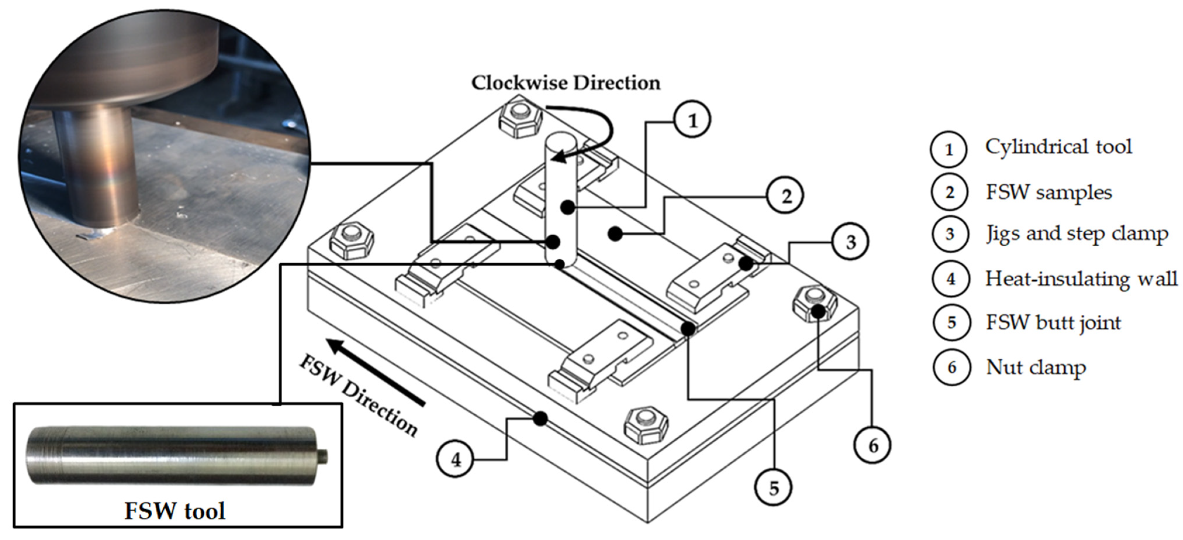
2.2. Friction Stir Welding (FSW) Process

For the FSW specimen, the plates were shaped according to the following dimensions in a butt joint formation: 60 mm wide, 100 mm long, and 4 mm thick. The two sample plates were firmly clamped, and a heat-insulating wall was inserted between the top and bottom jigs to prevent heat dissipation during the welding process. The FSW tool was cylindrical, with a 20 mm diameter tool shoulder and a pin that was 3.2 mm long and 5.0 mm in diameter. The welding tool was manufactured using SKH 57 high-strength steel, as shown in Figure 2. The FSW parameters were selected based on previous experiments [18]. These parameters were deemed suitable for FSW SSM 6063 aluminum alloy because they did not exhibit defects after welding (see Table 4).
After FSW, the microstructures of all samples were analyzed to evaluate the soundness of welds and defects with visual and OM analysis prior to the fatigue test. It was determined that post-welding defects reduce fatigue behavior. After preliminary testing, a rotational speed of 1320 rpm and travel speed of 60 mm/min indicated the excellent performance of the weld joint, which was free of defects in the stir zone (SZ), retreating-side thermomechanically affected zone (RS-TMAZ), and advancing-side thermomechanically affected zone (AS-TMAZ). However, the globular α-primary aluminum matrix phase and β-eutectic phase from the Al5FeSi intermetallic compounds were energized by mechanical force, causing plastic deformation. A fine grain was observed in the SZ region, whereas an elongated grain was observed in the RS-TMAZ and AS-TMAZ [19], as shown in Figure 3.

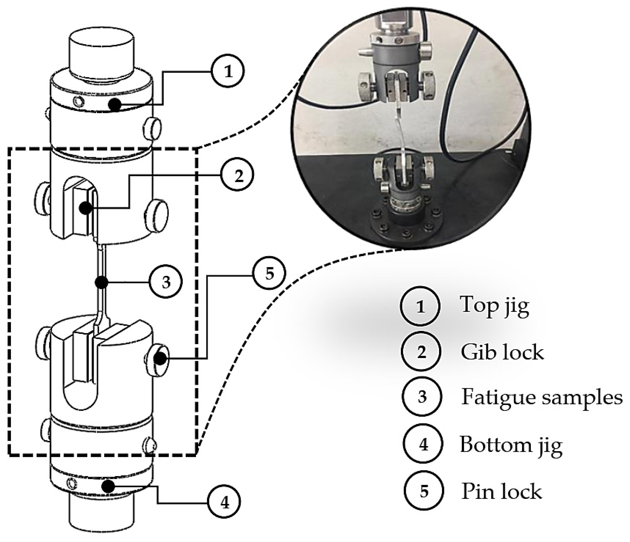
2.3. Fatigue Testing

The welded samples that passed the completeness examination were prepared as fatigue samples. The samples were prepared for fatigue testing according to the American Society for Testing of Materials standard for ASTM E466–15 [20]. The surfaces of the samples were machined with a wire-cutting machine (brand: Sodick; model: VL400Q (Schaumburg, IL, USA)). Each sample was 20 mm wide, 150 mm long, and 4 mm thick (samples were polished with 1200-grit sandpapers on the cut surface for smoothening), as shown in Figure 4.
Amplitude fatigue tests were used and adjusted to a frequency of 20 Hz and a stress ratio of R = −1. The stroke parameters of stress amplitude in this experiment were 0.35, 0.40, 0.45, 0.50, 0.60, 0.70, and 0.80 mm. A fatigue machine was used (brand: NARIN; model: NRI-FAT500-2 (Samut Prakarn, Thailand)). This machine sets stroke parameters instead of stress values. A fatigue temperature test was conducted at room temperature (30 °C). The maximum number of testing cycles for both the FSW samples and the base metal (BM) samples was limited to 2 × 10⁶ cycles; if the samples reached this limit without breaking, the test was terminated automatically. The relationship between stress amplitude values and the number of cycles was used to generate an S-N curve. Meanwhile, the stress amplitude values and number of cycles were calculated to form the fatigue life equation and determine the endurance limit. After that, an equation was formed based on Basquin’s equation to predict the fatigue life. The schematic drawing fatigue tests for the FSW SSM 6063 aluminum alloys are shown in Figure 5. For each stroke level, 7 repeats were tested.

2.4. Metallurgy Analysis

The samples used for the microstructure analysis and amplitude fatigue tests were prepared with different abrasive papers (600, 800, 1000, and 1200 grit). Next, the samples were polished with alumina powder with micro-particle sizes of 3 µm and 1 µm (Buehler brand, Illinois, USA) and etched with Keller’s reagent for approximately 12 s. Finally, the samples underwent electro-polishing in 30% HNO3 and 70% CH3OH at −20 °C and 30 V (brand: Struers; model: Tenupol-2 twin-jet electro-polisher, France). The microstructure was analyzed within a 3-week period using a transmission electron microscope (TEM) (FE-TEM/STEM: Thermo Scientific, model: TALOS F200X, Massachusetts, USA) to evaluate dislocation substructures in the BM, SZ, AS-TMAZ, and RS-TMAZ. To evaluate the characteristics of the fracture surface after fatigue testing, scanning electron microscopy (SEM) was performed using an FEI-Quanta, model 400FEG (Zurich, Switzerland).

3. Results and Discussion

3.1. Fatigue Stress Amplitude Results

The relationships between stress amplitude and the number of cycles to failure are shown in Table 5. The results show that the BM of the SSM 6063 aluminum alloy has a better ability to withstand fatigue behavior than the FSW samples. A new recrystallized microstructure in the fatigue samples was observed. The AS-TMAZ fatigue sample was damaged by heat fluctuations; the heat from the SZ radiated outward, causing the grain to grow and coarsen [21]. The lower stress amplitude significantly increased the number of cycles. For the maximum number of cycles, which was limited to 2 × 10⁶ cycle fatigue tests, no BM samples with a stress amplitude lower than 42.46 MPa failed the fatigue tests. Meanwhile, for the FSW samples with a stress amplitude lower than 33.12 MPa, the fatigue failures ranged from 50 to 90 percent or 75 MPa to 134 MPa for all mechanical properties, often resulting in severe damage [22]. However, increases in strokes reduced the number of cycles due to accumulated fatigue stress. This could be inferred from the stroke test for BM at 0.45 mm, with a stress amplitude of 45.79 MPa and 1,655,334 cycles. In contrast, for the stroke test performed at 0.80 mm, a stress amplitude of 101.72 MPa and 1747 cycles were recorded due to severe fluctuations in the dynamic state [23] and the dislocation substructures, causing permanent ruptures [24]. Likewise, for the FSW samples of SSM 6063 aluminum alloy, the stress amplitude varied according to the stroke test. This can be proven by the 0.50 to 0.70 mm increase in the stoke tests, which caused the stress amplitude to increase from 55.52 to 75.10 MPa; conversely, the number of cycles continuously decreased from 457,134 to 6104. The decline in cycles can be attributed to the dynamic loads causing cracks within the globular grains in the grain boundary [25]. In addition, micro-crack defects in the SZ caused by the FSW process affected the fatigue behavior of the SSM 6063 aluminum alloy [26]. A fatigue S-N curve for the BM and FSW SSM 6063 aluminum alloys was plotted, as shown in Figure 6. The results show a trend in the number of cycles from the low stroke test and stress amplitude, consistent with both the BM and FSW samples. Nevertheless, maintaining weld integrity and reducing residual stress at the SZ can increase the likelihood of ameliorating fatigue behavior [27]. The FSW process also transforms Al₅FeSi intermetallic compounds into the T-phase, and some parts move to the Guinier–Preston (GP) zone within the SZ. Therefore, this structure is resistant to high stress levels.
Table 6 shows the endurance limit at 2 × 10⁶ cycles. The calculated endurance limit of the BM SSM 6063 aluminum alloy is 42.50 MPa, whereas the endurance limit for the FSW SSM 6063 aluminum alloy is lower, at 32.40 MPa. This was due to the new precipitate of the β-eutectic phase and the α-primary aluminum matrix phase in the SZ region [28]. Other findings were attributed to cracks; the kissing bond; the lack of penetration from a tunnel, void, or cavity; and the formation of dendrite defects in the FSW process used on the SSM 6063 aluminum alloy [29,30].
For the regression equation of the SSM 6063 aluminum alloy fatigue test samples, fatigue life informs Basquin’s equation. This demonstrates a linear regression relationship [31] that can be determined using Equation (1). This regression equation was obtained from a log–log graph during the second period of growth; it was then transformed into a new equation to predict fatigue life, as shown in Equation (2).
σ R = A N R B
N = 10 1 b ( log σ log a )
According to the above equation to predict the fatigue life, based on Basquin’s equation, the results from the experimental data in Table 4 from the BM alloy were calculated using the least squares method (log–log scale) and the intercepts of a = 287.82 and b = −0.133, resulting in Equation (3). The FSW SSM 6063 aluminum alloy was evaluated to predict its fatigue life in Equation (4) based on intercepts of a = 268.08 and b = −0.137.
N = 10 1 0.133 ( log σ log 287.82 )
N = 10 1 0.137 ( log σ log 268.08 )
However, the fatigue failure of the samples was caused by crack defects. Microstructure transformation after using FSW on β-Al5FeSi intermetallic compounds is another factor that directly affects fatigue behavior. β-Al5FeSi intermetallic compounds have a small and evenly distributed structure, with good strength and toughness. The fine grain size results for crack resistance were also promising, offering a potential reduction in cleavage formation and the potential to prevent crack development [32].

3.2. Characteristics of the Fracture Surface After Fatigue Testing

The sample showing an optimum fatigue testing result was used to evaluate the behavior of materials under repeated or cyclic loading, in which materials experience fluctuating stress, resulting in different fracture surface characteristics in each zone. The position of fracture was only observed in AS-TMAZ. Initial crack zones are regions in which a material begins to crack under specific loading conditions [33]. This zone is crucial for understanding the initiation of fractures, especially in the context of fatigue testing, where cyclic loading is applied, as shown in Figure 7a. The vibration resulting from the amplitude of the force in fatigue testing leads to a ruptured laminar crack zone (Figure 7b). The cyclic loading from amplitude fatigue testing causes the forces to act in parallel to a specific plane. One part of the material slides or moves relative to the adjacent part, creating shear fractures. The shear fracture zone can occur in both ductile and brittle materials, but the characteristics of the fracture surface may vary. In ductile shear fractures, deformation features like dimples and necking may be visible, as shown in Figure 7c and observed by Mohammad et al. [34]. In this study, the ductile fracture zone underwent noticeable plastic deformation in response to stress. The fracture surface typically features a cup-shaped region where necking occurs, and a cone-shaped region representing the final separation was investigated [35] (Figure 7d). Ductile materials with high toughness can withstand dynamic or impact loading more effectively. The crack propagation zone is the area where a crack in the material advances or extends over time. This zone is particularly important in fracture mechanics and fatigue testing. Once the crack initiates, it begins to propagate or extend through the material, creating a crack propagation zone, as reported by SreeArravind Mani et al. [36] (Figure 7e). A bigger crack can be observed in Figure 7e due to the high stress level. Finally, overload crack zone events involve stress levels beyond what a material can withstand, leading to unique features on the fracture surface. In the overload crack zone, a crack may experience a sudden acceleration in growth due to higher-than-normal applied stress. The overload event can lead to rapid crack extension and, ultimately, failure [37]. The fracture surface characteristics obtained from samples broken during fatigue testing are shown in Figure 7f. When a higher stress level is introduced far beyond the strength that the material can support, it leads to a sudden crack.

3.3. Transmission Electron Microscope (TEM) Analysis

The TEM images show that the dislocation substructures in the BM zone take the form of a crystal lattice structure after the original S/S structure of the materials, significantly influencing their mechanical properties, as demonstrated in Figure 8. According to our evaluation, the width of the dislocation substructure is approximately 50–90 nm and has an estimated length of more than 700 nm, which is a characteristic of an alternating arrangement, as shown in Figure 8a. The dislocation substructures are concentrated in the grain boundary region. These atoms can form independently at the dislocation substructures and the crystal lattice where the arrangement of atoms deviates from the original formation, as shown in Figure 8b. However, grain boundaries with edged or mixed dislocations are deformed [38]. Simultaneously, the T-phase has an even, needle-shaped distribution, as shown in Figure 8c. The T-phase characteristics are transformed from the intermetallic compounds of Al5FeSi particles, with estimated widths of approximately 10–40 nm and lengths of more than 500-700 nm. The T-phase of BM is not affected by cyclic loading force and thus has good resistance to fatigue behavior, as reported by Sillapasa et al. [39].
However, because of the mechanical force of the FSW tool, the dislocation substructures are transformed into a SZ. The changes in the T-phase and dislocation substructures (Figure 9a–c) also result in a new recrystallization particle structure in the SZ. The α-primary aluminum matrix phase precipitates from an S/S to an S/S’ structure. The dislocation substructures with the characteristic crystal lattice structure are destroyed, creating a new plate-like arrangement of dislocation substructures, as shown in Figure 9a. In addition, the T-phase SZ and near-grain-boundary transformations have a small, rod-like shape, and size alterations of approximately 10–20 nm in width and 20–30 nm in length can be measured (Figure 9b,c). In the SZ precipitate, a fine homogeneous combination of S/S’ and T-phase was investigated [40]. The dislocation substructures of the AS-TMAZ revealed that some zones of the S/S crystal lattice structure and T-phase were destroyed and plastically deformed (Figure 9d–f). The incomplete precipitate of the S/S’ crystal lattice structure and T-phase formed coarse particles and discontinuous dislocation substructures (Figure 9e). The T-phase in the AS-TMAZ is approximately 10–120 nm in width and 20–180 nm in length (Figure 9f). This results from the S/S’ structure and incomplete precipitation in the T-phase, generating temporary heat during FSW that could not be diffused to the AS-TMAZ. Generated heat is very important for FSW. Therefore, the appropriate temperature should be within 50–80 percent of the melting point (Tm) of the welding material. This could be the amount of heat left over after FSW, accumulated via stress prior to fatigue testing [41]. If the T-phase and GP zone distribution are good, this will support a better microstructure, increasing the strength value. Likewise, the generated heat eliminates defects, resulting in fatigue behavior [42]. In the same way, in the RS-TMAZ, the S/S’ structure and T-phase were incompletely precipitated in this study, but they had a smaller particle size and more even distribution than the AS-TMAZ, which was approximately 10–70 nm in width and 20–110 nm in length. Consequently, during fatigue and tensile tests, the AS-TMAZs of the samples broke more easily than those of other areas [43]. However, cracks, a lack of penetration or tunnels, and permanent changes offer little resistance to fatigue, as these types of defects have a high rate of crack growth when cyclic loading is applied [44].
The TEM images show that all regions had clear differences in their dislocation substructures. These changes were caused by the heat generated by FSW and the mechanical forces exerted during stirring [45,46]. Alterations in the sizes and shapes of the S/S’ structure and T-phase are also important contributors to fatigue behavior. The complete formation of the S/S’ structure and T-phase (transformed Al5FeSi particles) will result in a GP zone, in which precipitation is in equilibrium, solidifying alloys containing Al or Mg in the solid solution state. The formation of the GP zone alternates in the form of needles and sheets, strengthening the material [47]. However, the successful formation of Mg and Si in the GP zone has also been reported by Knap et al. [48].

4. Conclusions

The results of this study on the fatigue behavior and dislocation substructures of FSW SSM 6063 aluminum alloy are as follows:
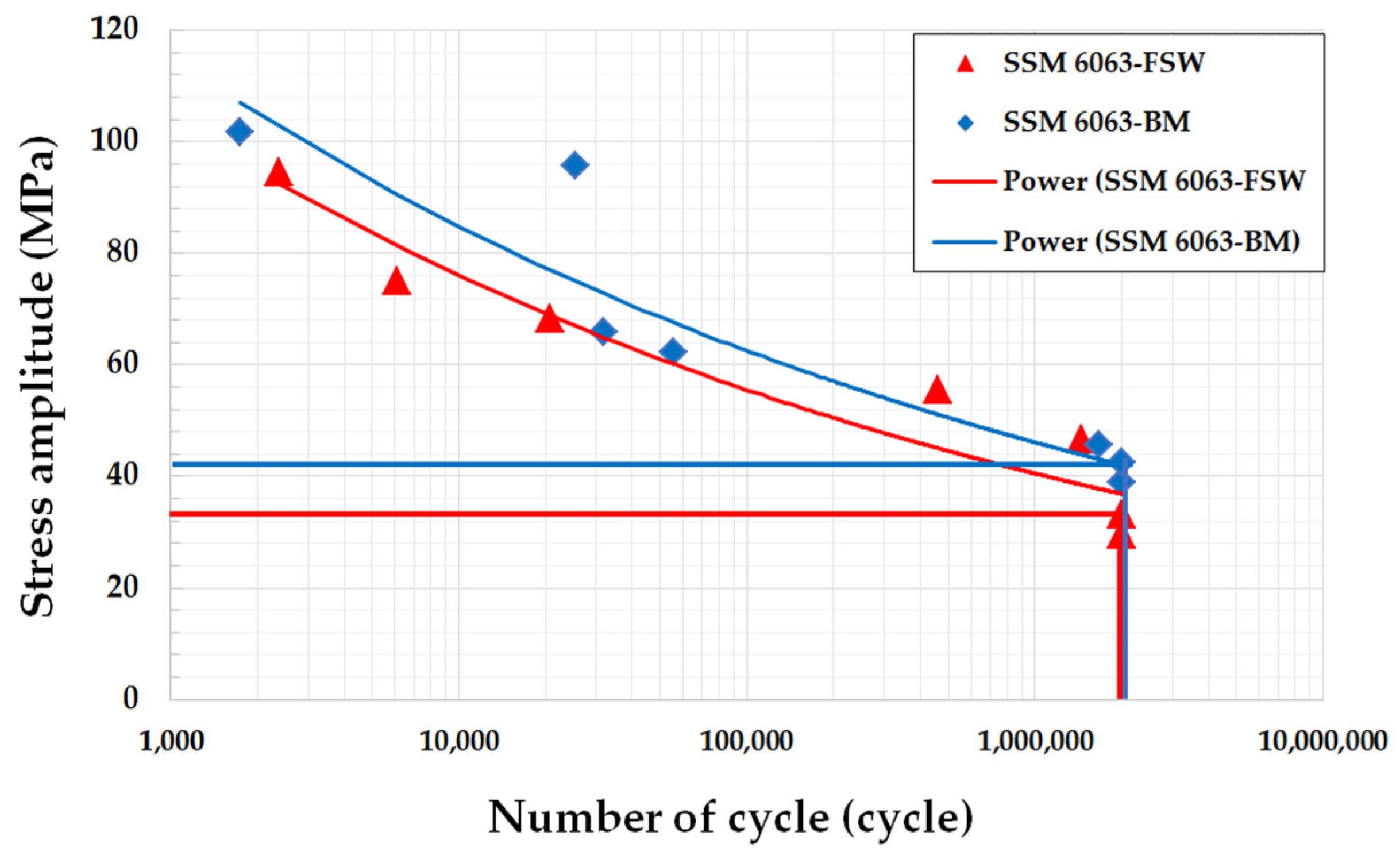
  • Fatigue testing for the set number of cycles (limited to 2 × 10⁶) revealed that the BM alloy can resist more than 2 × 10⁶ cycles of cyclic loading at a stress amplitude of 42.46 MPa, while for the FSW alloy the stress amplitude is 33.12 MPa. The calculated endurance limit of the BM was 42.50 MPa. Meanwhile, the FSW SSM 6063 aluminum alloy showed an endurance limit of 32.40 MPa in response to stroke testing at 0.4 mm.
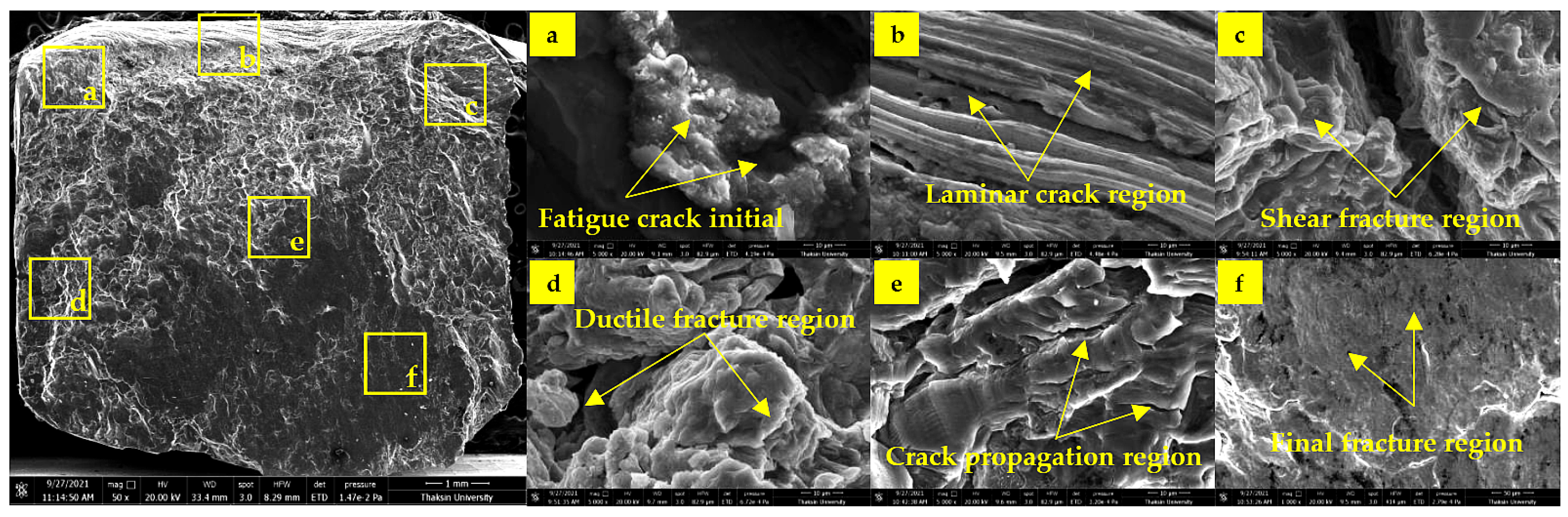
  • After fatigue testing, the fracture surface of the FSW samples exhibited plastic deformation behavior. There were two regions of interest: (1) a laminar crack zone, which was arranged in layers near the edge of the fatigue samples; and (2) a shear fracture surface zone, a crack surface caused by accumulated stress in an area near the damaged zone.
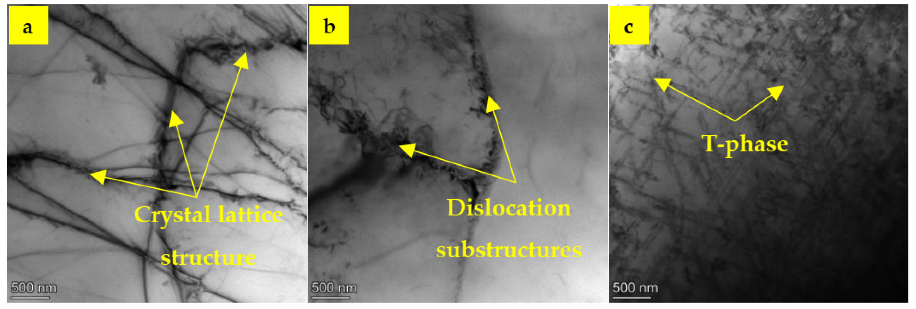
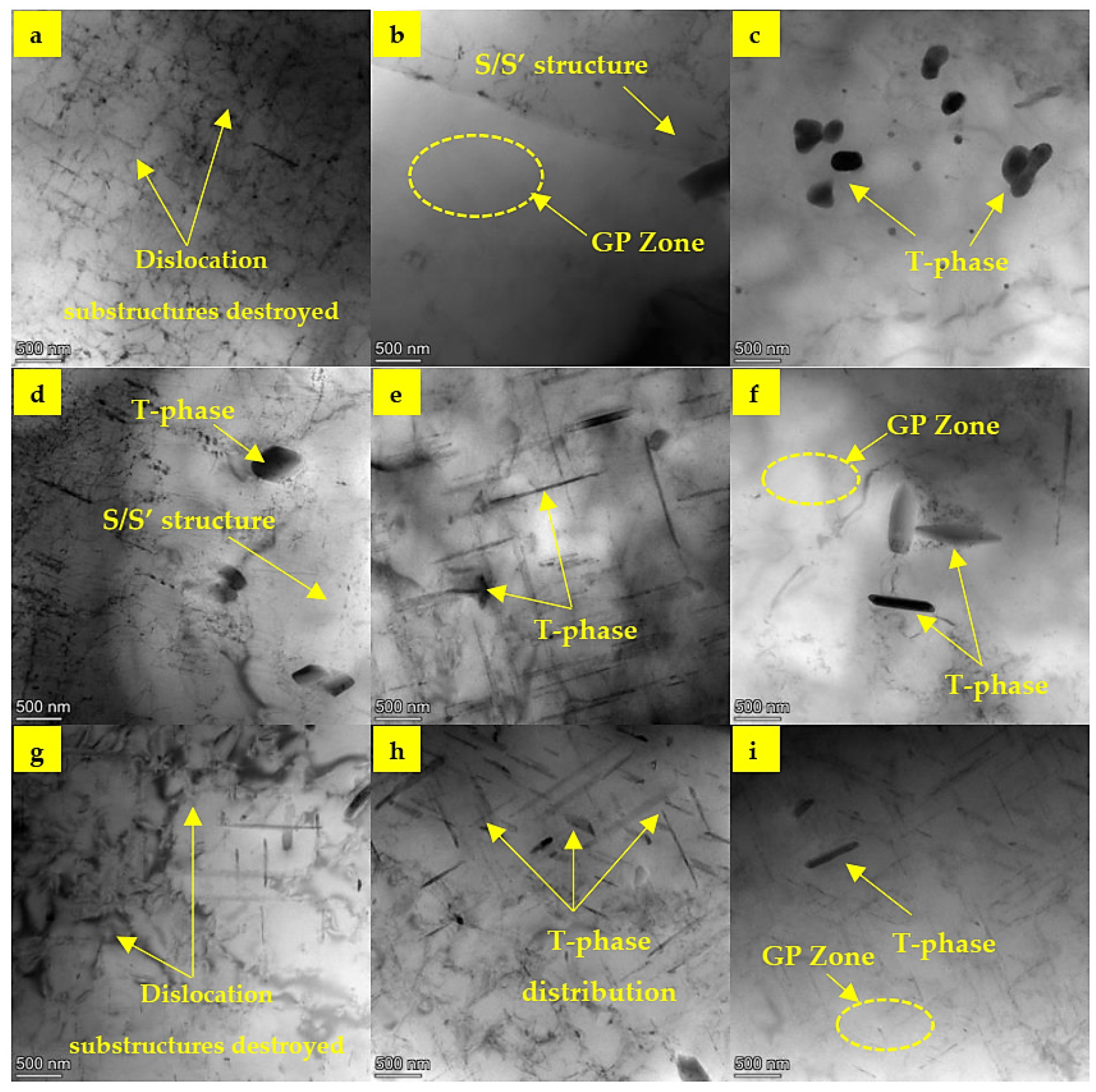
  • The microstructures revealed during the TEM examination demonstrated that cyclic loading resulted in dislocation substructures, which were subsequently transformed into the SZ, AS-TMAZ, and RS-TMAZ. The dislocation substructures were destroyed and precipitated from an α-primary aluminum matrix phase to an S/S’ structure and from Al5FeSi intermetallic compound recrystallization particles to the T-phase. In particular, in the T-phase transformations, the rod shapes and sizes in the SZ were smaller than in the other two zones (approximately 10–20 nm wide and 20–30 nm long in the SZ; 10–120 nm wide and 20–180 nm long in the AS-TMAZ; and 10–70 nm wide and 20–110 nm long in the RS-TMAZ).

Author Contributions

Conceptualization, K.S.; methodology, C.M.; validation, K.S.; formal analysis, C.M. and K.N.; investigation, K.S. and C.M.; data curation, C.M. and S.K.; software, S.K.; resources, S.K.; writing—original draft preparation, K.S. and C.M.; writing—review and editing, C.M. and K.N.; supervision, C.M.; project administration, K.S. All authors have read and agreed to the published version of the manuscript.

Funding

Financial support comes from the National Research Council of Thailand. (Project # JRA-CO-2564-15853-TH).

Data Availability Statement

The raw data supporting the conclusions of this article will be made available by the authors on request.

Acknowledgments

The authors gratefully acknowledge the Department of Engineering, Ubon Ratchathani University, for providing numerous resources. Thanks to all who contributed to this research, such as the Synchrotron Light Research Institute in Nakhon Ratchasima and GISSCO Company Limited (Songkhla, Thailand), who sponsored the FSW experiment.

Conflicts of Interest

The authors declare no conflicts of interest.

Abbreviations

The following abbreviations are used in this manuscript:
SSMSemi-solid metal
GISSGas-induced semi-solid
FSWFriction stir welding
ASTMAmerican Society for Testing of Materials standard
SEMScanning electron microscopy
TEMTransmission electron microscope
OMOptical microscopy
BMBase metal
SZStir zone
AS-TMAZAdvancing-side thermomechanically affected zone
RS-TMAZRetracting-side thermomechanically affected zone
TmMelting point
RLoad ratio (Pmin/Pmax)
GP zoneGuinier–Preston zone
S/S’Transformed α-primary aluminum matrix phase
T-phaseTransformed Al5FeSi intermetallic compounds

References

  1. El-Sayed, M.M.; Shash, A.Y.; Abd-Rabou, M.; ElSherbiny, M.G. Welding and processing of metallic materials by using friction stir technique: A review. J. Adv. Join. Process. 2021, 3, 100059. [Google Scholar] [CrossRef]
  2. Mjali, K.V.; Mkoko, Z.A. Varying rotational speeds and their effect on the mechanical properties of friction stir welded 6082-T651 aluminium alloy plates. Manuf. Lett. 2023, 35, 305–313. [Google Scholar] [CrossRef]
  3. Sivabalan, S.; Sridhar, R.; Parthiban, A.; Sathiskumar. Experimental investigations of mechanical behavior of friction stir welding on aluminium alloy 6063. Mater. Today Proc. 2021, 37, 1678–1684. [Google Scholar] [CrossRef]
  4. Wannasin, J.; Janudom, S.; Rattanochaikul, T.; Canyook, R.; Burapa, R.; Chucheep, T.; Thanabumrungkul, S. Research and development of gas induced semi-solid process for industrial applications. Trans. Nonferr. Met. Soc. China 2010, 20, 1010–1015. [Google Scholar] [CrossRef]
  5. Liu, X.; He, G.; Ding, X.; Mo, D.; Zhang, W.H. Fatigue behavior and dislocation substructures for 6063 aluminum alloy under nonproportional loadings. Int. J. Fatigue 2009, 31, 1190–1195. [Google Scholar] [CrossRef]
  6. SreeArravind, M.; Kumar, R.; Ravishankar, B.; Kumar, S. Low cycle fatigue behavior of aluminium 6063 alloy under the cyclic frequency of 0.2 Hz. Mater. Today Proc. 2020, 27, 2376–2380. [Google Scholar] [CrossRef]
  7. Sekhar, A.P.; Nandy, S.; Bakkar, A.; Ray, K.K.; Das, D. Low cycle fatigue response of differently aged AA6063 alloy: Statistical analysis and microstructural evolution. Materialia 2021, 20, 101219. [Google Scholar] [CrossRef]
  8. Lin, K.; Zhou, L.; Jensen, D.J.; Zhang, X. Dislocation Mechanisms and Local Strength with a View towards Sleeper Screw Failures. Crystals 2023, 13, 656. [Google Scholar] [CrossRef]
  9. Wang, G.; Che, X.; Zhang, Z.; Zhang, H.; Zhang, S.; Li, Z.; Sun, J. Microstructure and Low-Cycle Fatigue Behavior of Al-9Si-4Cu-0.4Mg-0.3Sc Alloy with Different Casting States. Materials 2020, 13, 638. [Google Scholar] [CrossRef]
  10. Wang, Y.; Chen, L.; Zhou, G.; Liu, R.; Zhang, S. Influence of 0.5% Ag Addition on Low-Cycle Fatigue Behavior of Hot-Extruded Al-5Cu-0.8Mg-0.15Zr-0.2Sc Alloy Subjected to Peak-Aging Treatment. Metals 2023, 13, 1734. [Google Scholar] [CrossRef]
  11. Kurek, M. Fatigue Prediction of Aluminum Alloys Considering Critical Plane Orientation under Complex Stress States. Materials 2020, 13, 3877. [Google Scholar] [CrossRef] [PubMed]
  12. Fitzka, M.; Mayer, H. Variable amplitude testing of 2024-T351 aluminum alloy using ultrasonic and servo-hydraulic fatigue testing equipment. Procedia Eng. 2015, 101, 169–176. [Google Scholar] [CrossRef]
  13. Sillapasa, K.; Mutoh, Y.; Miyashita, Y.; Seo, N. Fatigue Strength Estimation Based on Local Mechanical Properties for Aluminum Alloy FSW Joints. Materials 2017, 10, 186. [Google Scholar] [CrossRef]
  14. Wang, R.; Mi, P. Study on fatigue strength of FSW joints of 5083 aluminum alloy with kissing bond defect. J. Mech. Sci. Technol. 2020, 37, 2761–2766. [Google Scholar] [CrossRef]
  15. Chehreh, A.B.; Grätzel, M.; Bergmann, J.P.; Walther, F. Fatigue Behavior of Conventional and Stationary Shoulder Friction Stir Welded EN AW-5754 Aluminum Alloy Using Load Increase Method. Metals 2020, 10, 1510. [Google Scholar] [CrossRef]
  16. Takase, T.; Koyama, A.; Yamashita, Y.; Saki, H. Effect of specimen thickness on fatigue crack growth behavior of friction stir welded 6063-T5 aluminum alloy. Mech. Eng. J. 2016, 3, 16–00156. [Google Scholar] [CrossRef]
  17. Wannasin, J.; Canyook, R.; Wisutmethangoon, S.; Flemings, M.C. Grain refinement behavior of an aluminum alloy by inoculation and dynamic nucleation. Acta Mater. 2013, 61, 3897–3903. [Google Scholar] [CrossRef]
  18. Meengam, C.; Sillapasa, K. Evaluation of Optimization Parameters of Semi-Solid Metal 6063 Aluminum Alloy from Friction Stir Welding Process Using Factorial Design Analysis. J. Manuf. Mater. Process. 2020, 4, 123. [Google Scholar] [CrossRef]
  19. Meengam, C.; Dunyakul, Y.; Kuntongkum, S. A Study of the Essential Parameters of Friction-Stir Spot Welding That Affect the D/W Ratio of SSM6061 Aluminum Alloy. Materials 2023, 16, 85. [Google Scholar] [CrossRef]
  20. ASTM E466-15; Standard Practice for Conducting Force Controlled Constant Amplitude Axial Fatigue Tests of Metallic Materials. Designation. ASTM International Standards: West Conshohocken, PA, USA, 2015.
  21. Liu, K.; Wang, S.; Pan, L.; Chen, X.-G. Thermo-Mechanical Fatigue Behavior and Resultant Microstructure Evolution in Al-Si 319 and 356 Cast Alloys. Materials 2023, 16, 829. [Google Scholar] [CrossRef]
  22. Lee, B.-H.; Park, S.-W.; Hyun, S.-K.; Cho, I.-S.; Kim, K.-T. Mechanical Properties and Very High Cycle Fatigue Behavior of Peak-Aged AA7021 Alloy. Metals 2018, 8, 1023. [Google Scholar] [CrossRef]
  23. Teng, Y.; Xie, L.; Zhang, H. Experimental Study on Vibration Fatigue Behavior of Aircraft Aluminum Alloy 7050. Materials 2022, 15, 7555. [Google Scholar] [CrossRef] [PubMed]
  24. Zhao, H.; Engler-Pinto, C.C.; Tong, J.; Godlewski, L.A.; Zindel, J.W.; Li, L.; Li, M.; Feng, Q. Mechanical response and dislocation substructure of a cast austenitic steel under low cycle fatigue at elevated temperatures. Mater. Sci. Eng. A. 2017, 703, 422–429. [Google Scholar] [CrossRef]
  25. Moreira, P.; de Oliveira, F.; de Castro, P. Fatigue behaviour of notched specimens of friction stir welded aluminium alloy 6063-T6. J. Mater. Process. Technol. 2008, 207, 283–292. [Google Scholar] [CrossRef]
  26. Patel, M.; Sangral, S.; Murugesan, J.; Mutoh, Y. Effect of friction stir processing on plain fatigue and fretting fatigue behaviour of the AA6063 alloys. Tribol. Int. 2023, 168, 108642. [Google Scholar] [CrossRef]
  27. Kumar, S.; Srivastava, A.K.; Singh, R.K.; Dwivedi, S.P. Experimental study on hardness and fatigue behavior in joining of AA5083 and AA6063 by friction stir welding. Mater. Today Proc. 2020, 20, 646–648. [Google Scholar] [CrossRef]
  28. Zhao, X.; Li, H.; Chen, T.; Cao, B.; Li, X. Mechanical Properties of Aluminum Alloys under Low-Cycle Fatigue Loading. Materials 2019, 12, 2064. [Google Scholar] [CrossRef]
  29. Tra, T.H.; Okazaki, M.; Suzuki, K. Fatigue crack propagation behavior in friction stir welding of AA6063-T5: Roles of residual stress and microstructure. Int. J. Fatigue 2012, 43, 23–29. [Google Scholar] [CrossRef]
  30. Das, J.; Banik, S.R.; Reddy, S.R.S.K.; Robi, P.S. Review on process parameters effect on fatigue crack growth rate in friction stir welding. Mater. Today Proc. 2019, 18, 3061–3070. [Google Scholar]
  31. Bahmanabadi, H.; Shamsarjmand, M. Modeling of fatigue behavior in pre-corroded AZ31 magnesium alloy. Forces Mech. 2024, 14, 100254. [Google Scholar] [CrossRef]
  32. Łagoda, T.; Głowacka, K.; Kurek, A. Fatigue Life of Aluminum Alloys Based on Shear and Hydrostatic Strain. Materials 2020, 13, 4850. [Google Scholar] [CrossRef] [PubMed]
  33. Cao, X.; Xu, L.; Xu, X.; Wang, Q. Fatigue Fracture Characteristics of Ti6Al4V Subjected to Ultrasonic Nanocrystal Surface Modification. Metals 2018, 8, 77. [Google Scholar] [CrossRef]
  34. Amooie, M.A.; Lijesh, K.P.; Mahmoudi, A.; Azizian-Farsani, E.; Khonsari, M.M. On the Characteristics of Fatigue Fracture with Rapid Frequency Change. Entropy 2023, 25, 840. [Google Scholar] [CrossRef]
  35. Murashkin, M.; Sabirov, I.; Prosvirnin, D.; Ovid’Ko, I.; Terentiev, V.; Valiev, R.; Dobatkin, S. Fatigue Behavior of an Ultrafine-Grained Al-Mg-Si Alloy Processed by High-Pressure Torsion. Metals 2015, 5, 578–590. [Google Scholar] [CrossRef]
  36. Mani, S.; Subramanian, R.K. Experimental investigation on the low cycle fatigue performance and fractographic analysis of deep cryogenic treated 6063 aluminium alloy. Structures 2023, 58, 105588. [Google Scholar] [CrossRef]
  37. González, J.; Bagherifard, S.; Guagliano, M.; Pariente, I.F. Influence of different shot peening treatments on surface state and fatigue behaviour of Al 6063 alloy. Eng. Fract. Mech. 2017, 185, 72–81. [Google Scholar] [CrossRef]
  38. Ellard, J.J.M.; Mathabathe, M.N.; Siyasiya, C.W.; Bolokang, A.S. Low-Cycle Fatigue Behaviour of Titanium-Aluminium-Based Intermetallic Alloys: A Short Review. Metals 2023, 13, 1491. [Google Scholar] [CrossRef]
  39. Sillapasa, K.; Surapunt, S.; Miyashita, Y.; Mutoh, Y.; Seo, N. Tensile and fatigue behavior of SZ, HAZ and BM in friction stir welded joint of rolled 6N01 aluminum alloy plate. Int. J. Fatigue 2014, 63, 162–170. [Google Scholar] [CrossRef]
  40. Zhang, L.; Zhong, H.; Li, S.; Zhao, H.; Chen, J.; Qi, L. Microstructure, mechanical properties and fatigue crack growth behavior of friction stir welded joint of 6061-T6 aluminum alloy. Int. J. Fatigue 2020, 135, 105556. [Google Scholar] [CrossRef]
  41. Sivaraj, P.; Kanagarajan, D.; Balasubramanian, V. Fatigue crack growth behaviour of friction stir welded AA7075-T651 aluminium alloy joints. Trans. Nonferrous Met. Soc. China 2014, 24, 2459–2467. [Google Scholar] [CrossRef]
  42. Besel, Y.; Besel, M.; Mercado, U.A.; Kakiuchi, T.; Hirata, T.; Uematsu, Y. Influence of local fatigue damage evolution on crack initiation behavior in a friction stir welded Al-Mg-Sc alloy. Int. J. Fatigue 2017, 99, 151–162. [Google Scholar] [CrossRef]
  43. Mao, X.; Yi, Y.; He, H.; Huang, S.; Guo, W. Second Phase Particles and Mechanical Properties of 2219 Aluminum Alloys Processed by an Improved Ring Manufacturing Process. Mater. Sci. Eng. A 2020, 781, 139226. [Google Scholar] [CrossRef]
  44. Zhang, Z.; Huang, C.; Chen, S.; Wan, M.; Yang, M.; Ji, S.; Zeng, W. Effect of Microstructure on High Cycle Fatigue Behavior of 211Z.X-T6 Aluminum Alloy. Metals 2022, 12, 387. [Google Scholar] [CrossRef]
  45. Sun, C.; Song, Q. A Method for Predicting the Effects of Specimen Geometry and Loading Condition on Fatigue Strength. Metals 2018, 8, 811. [Google Scholar] [CrossRef]
  46. Zhang, R.; Zhao, W.; Zhang, H.; Yang, W.; Wang, G.; Dong, Y.; Ye, C. Fatigue Performance Rejuvenation of Corroded 7075-T651 Aluminum Alloy through Ultrasonic Nanocrystal Surface Modification. Int. J. Fatigue 2021, 153, 106463. [Google Scholar] [CrossRef]
  47. Mao, X.; Yi, Y.; Huang, S.; Guo, W.; He, H.; Que, J. Effects of Warm Saddle Forging Deformation on the Reduction of Second-Phase Particles and Control of the Three-Dimensional Mechanical Properties of 2219 Aluminum Alloy Rings. Mater. Sci. Eng. A 2021, 804, 140737. [Google Scholar] [CrossRef]
  48. Knap, V.; Švecová, I.; Tillová, E.; Kuchariková, L. Influence of Iron Content on SDAS Factor, Al5FeSi Intermetallic Phases and Porosity of the Secondary Aluminum Alloy AlSi7Mg0.6 Used in the Automotive Industry. Transp. Res. Procedia 2021, 55, 814–820. [Google Scholar] [CrossRef]
Figure 1. The globular-shaped base microstructure of SSM 6063 aluminum alloy.
Jmmp 09 00128 g001
Figure 2. Schematic of the dimensions of the FSW butt joint of the SSM 6063 aluminum alloys.
Jmmp 09 00128 g002
Figure 3. Micrographs of the macro–microstructure of the FSW joint of SSM 6063 aluminum alloys were evaluated using OM images of AS-TMAZ, SZ, and RS-TMAZ.
Jmmp 09 00128 g003
Figure 4. The fatigue test specimen with dimensions according to the ASTM E466–15 standard.
Jmmp 09 00128 g004
Figure 5. The amplitude fatigue tests for FSW SSM 6063 aluminum alloys.
Jmmp 09 00128 g005
Figure 6. S-N curve graphs for the BM and FSW SSM 6063 aluminum alloys.
Jmmp 09 00128 g006
Figure 7. The failure fracture surface after fatigue testing on FSW SSM 6063 aluminum alloy: (a) initial crack zone, (b) laminar crack zone, (c) shear fracture surface, (d) ductile fracture zone, (e) crack propagation zone, and (f) overload crack zone.
Jmmp 09 00128 g007
Figure 8. TEM micrograph of BM SSM 6063 aluminum alloy: (a) crystal lattice structure, (b) dislocation substructures in the grain boundary, and (c) T-phase.
Jmmp 09 00128 g008
Figure 9. TEM micrograph of dislocation substructures and T-phase of SSM 6063 aluminum alloy caused by FSW: (ac) SZ, (df) AS-TMAZ, and (gi) RS-TMAZ.
Jmmp 09 00128 g009
Table 1. Highlights of previous research on fatigue behavior of FSW aluminum alloys.
WorkpieceFrequencyStress RatioMaximum CyclesFatigue
Parameters
Recommended
Parameters
Reference
Material:
Al 2024-T351 Thickness:
4 mm
20 kHzR = 0.1 and 0.5107 cyclesThe sequence consists of 27 discrete levels between fractions of 0.31 and 1.0 of the nominal amplitude in a succession of 771 realizations.High-frequency and adapted testing may influence fatigue properties; 2024-T351 aluminum alloy shows comparable lifetimes for constant amplitude tests at load ratios of R = 0.1 and R = 0.5.[12]
Material:
6N01-7N01 Thickness:
6.0 mm
20 HzR = 0.1107 cyclesThe stress amplitude ranges from 70 to 140 N/mm2, and two types of test specimens are available: plate and small round bar specimen fatigue testing. The fatigue strength of FSW 6N01-7N01 at 72 N/mm2 and the relationship between the
fatigue strength and hardness of aluminum alloys were investigated.
[13]
Material:
AA 5083
Thickness:
3 mm
10 HzR = 0.12 × 10⁶ cyclesLoad amplitudes at 2420, 2480, 2530, 2640, 2750, 2860, 3300, 3850, 4400, 4950, 5500, and 5770 N. Kissing bond defect depth has an obvious effect on the fatigue behavior and maximum fatigue life with 142,743 cycles at a load amplitude of 2480 N and a kissing bond defect depth of 0.45 d/mm.[14]
Material:
AW-5754
Thickness:
2 mm
10 HzR = 0.12 × 10⁵ cyclesThe σmax value is 20 MPa, and the σ0/dN value is 10 MPa/104. The surface roughness measurements of the FSW specimen are Rz = 212 µm and Ra = 23 µm.Load increases the efficiency of fatigue
performance and strength of materials. FSW EN AW-5754 is tolerant to fatigue behavior due to its fatigue life and fracture stress, reduced scatter, and deviation.
[15]
Material:
SSM6063
Thickness:
4 mm
20 HzR = 0.12 × 10⁶ cyclesStrokes at 0.35, 0.40, 0.45, 0.50, 0.60, 0.70, and 0.80 mm.This research studies the amplitude fatigue of SSM 6063 aluminum alloy, a new material for semi-solid casting. It focuses on the dislocation substructures that affect the S-N curve, which have not been previously studied.Present work
Table 2. The chemical composition of SSM 6063 aluminum alloy (wt%) [17].
Element (wt %)SiFeCuMnMgZnTiCrAl
SSM 60630.600.350.100.100.450.100.100.10Rem.
Table 3. Mechanical properties of SSM 6063 aluminum alloy [17].
Young’s ModulusTensile Strength0.2% Proof StressElongation
68 GPa149 ± 3 MPa68 ± 4 MPa27 ± 4%
Table 4. The FSW parameters of the SSM 6063 aluminum alloys.
ParameterUnitValueAffected Process
Rotational speedrpm1320Heat inputs, plasticity
Travel speedmm/min60Welding completeness
Plunge ratemm/min9Heat initiation
Dwell times12Heat accumulation
Pin lengthmm3.2Thickness of the samples
Pin diametermm5Stirring pattern
Shoulder diametermm20Heat transfer area
Direction of FSW---clockwiseMaterial flows
Table 5. Stress amplitude and number of cycles: data results for the BM and FSW SSM 6063 aluminum alloys.
Stroke
(mm)
SSM 6063 (BM)SSM 6063 (FSW)
Stress (MPa)Number of CyclesStress (MPa)Number of Cycles
0.3538.922,000,000 *29.472,000,000 *
0.4042.462,000,000 *33.122,000,000 *
0.4545.791,655,33446.721,440,470
0.5062.2455,56055.52457,134
0.6065.8131,83568.3120,780
0.7095.6625,46575.106104
0.80101.72174794.522360
* The samples did not show any signs of broken pieces from the stress test; therefore, the authors decided to stop the test.
Table 6. Fatigue life equation and endurance limit for the BM and FSW SSM 6063 aluminum alloys.
MaterialFatigue Life Equation at 2 × 10⁶ CyclesEndurance Limit (MPa)
SSM 6063—BMσ = 287.82x−0.13342.50
SSM 6063—FSWσ = 268.08x−0.13732.40
Disclaimer/Publisher’s Note: The statements, opinions and data contained in all publications are solely those of the individual author(s) and contributor(s) and not of MDPI and/or the editor(s). MDPI and/or the editor(s) disclaim responsibility for any injury to people or property resulting from any ideas, methods, instructions or products referred to in the content.

