Article

Process Chain Optimization for SWCNT/Epoxy Nanocomposite Parts with Improved Electrical Properties

Polymer Engineering Department, Fraunhofer Institut für Chemische Technologie (ICT), Joseph-von-Fraunhofer-Straße 7, 76327 Pfinztal, Germany
*
Author to whom correspondence should be addressed.
J. Compos. Sci. 2020, 4(3), 114; https://doi.org/10.3390/jcs4030114
Submission received: 17 July 2020 / Revised: 5 August 2020 / Accepted: 11 August 2020 / Published: 14 August 2020
(This article belongs to the Special Issue Discontinuous Fiber Composites, Volume II)

Abstract

:
Electrically conductive nanocomposites present opportunities to replace metals in several applications. Usually, the electrical properties emerging from conductive particles and the resulting bulk values depend on the micro/nano scale morphology of the particle network formed during processing. The final electrical properties are therefore highly process dependent. In this study, the electrical resistivity of composites made from single-walled carbon nanotubes in epoxy was investigated. Three approaches along the processing chain were investigated to reduce the electrical resistivity of nanocomposites-the dispersion strategy in a three-roll mill, the curing temperature, and the application of electric fields during curing. It was found that a progressive increase in the shear forces during dispersion leads to a more than 50% reduction in the electrical resistivities. Higher curing temperatures of the nanocomposite resin also lead to a decrease of around 50% in resistivity. Furthermore, a scalable resin transfer molding set-up with gold-coated electrodes was developed and tested with different mold release agents. It has been shown that curing the material under electric fields leads to an electrical resistivity approximately an order of magnitude lower, and that the properties of the mold release agent also influence the final resistivity of different samples in the same batch.

1. Introduction

With the dispersion of discontinuous micro or nanofibers, such as carbon nanotubes (CNTs), in a polymer matrix, it is possible to obtain composite materials with mechanical and electrical properties that open a vast range of applications. Depending on the composition, particle concentration and dispersion, these materials have an electrical conductivity ranging from electrical insulation (10−18–10−7 Scm−1), to semi-conductivity (10−7–10−1 Scm−1) or even metallic conductivity (above 10−1 Scm−1), allowing for higher flexibility in applications when compared to plastics and metals that possess a unique and defined conductivity [1]. Electrically conductive polymer composites may be able to substitute metals in a variety of applications that allow for lightweight solutions and easy shaping, such as resistive or capacitive sensors, battery technology components, electromagnetic shielding or resistive heating elements [2,3,4].
The electrical properties in these functional composite materials arise due to a network of interconnected particles which ultimately allows for the flow of electrons. This network not only depends on the particle shape and properties, but also on all the processing steps of the material, from the compounding of matrix and particles up to the shaping of the final part. Therefore, the complete history of the material affects the final electrical properties of the composite in the final parts [5,6,7]. Traditionally, the best way to reduce electrical resistivity is to increase the particle concentration, which entails additional costs and affects the processability due to higher viscosity [8].
The CNTs dispersive mixing operation consists of several stages-filler incorporation and the wetting and infiltration of the epoxy matrix, followed by dispersion, distribution and flocculation [9,10]. During the stage of filler dispersion, the large initial filler agglomerates are reduced in size up to the smallest dispersible unit. This can be mainly attributed to two coexisting mechanisms: rupture (a bulk phenomenon) and erosion (a surface phenomenon). The rupture mechanism breaks down agglomerates in a short time, related to erosion that happens slower by removing single or bundles of CNTs from the surface of the agglomerate [11]. This first step is the most difficult and important one, since it determines the rate at which CNTs disperse in the polymer. The prevalence of a mechanism over the other depends on the shear stress: if it exceeds a certain threshold value (dependent on the filler) the rupture tends to be the dominant mechanism [12]. From the existing literature [13] it emerges that the ratio of applied shear stress and cohesive strength of the agglomerate defines the dominating mechanism. Dispersion by rupture is the fastest way to obtain small final agglomerates, but the sudden breaking of a whole cluster often implies a reduction in the aspect ratio of its constituent particles, resulting in a worsening of the macroscopic properties that the nanoparticles can give to the composite. To avoid the excessive breakages of single nanotubes, the mixing parameters should be ideally controlled in order to maintain the rupture mechanism at the lowest possible rate, promoting erosion that is slow but preserving the nanotube aspect ratio, and leading to a better infiltration of the epoxy matrix in the agglomerates [11].
Finally, this work presents a scalable method to investigate and produce nanocomposite samples with improved controlled electrical properties by manipulating the nanoparticles with electric fields during the shaping step [14,15]. This is possible due to the difference in dielectric and electric properties between the particles and matrix, and particularly due to the high aspect ratio of carbon nanotubes [16,17]. According to the theory of dielectrophoresis, randomly dispersed particles under an electric field become polarized and orient, interacting due to Coulomb forces and assembling in conductive chains [16,17,18].
The experimental set-up hereby developed is inspired in resin-transfer-molding (RTM) [19] and allows for the application of an electric field on the electrically conductive composite resin during the curing. It was designed to be easily scaled-up for different plate geometries and integrated with available composite technology, aiming at an industrial-relevant production. It is here demonstrated for a system of single-wall carbon nanotubes (SWCNTs) and epoxy. In a first step, the process of dispersion of SWCNT in epoxy is investigated in view of optimization of electrical resistivity. Then, this nanocomposite is cured under the influence of electrical fields, and the impact of different mold release agents on the final resistivity is investigated.

2. Materials and Methods

The experimental procedure for the production of bulk epoxy nanocomposites was done in the following steps:
  • Dispersion of nanoparticles in the liquid resin (with a three-roll mill);
  • Addition of the curing agent in the correct stoichiometric amount;
  • Feeding the mold, setting the electric field and the curing temperature;
  • After reaction completion, removal of the field and retrieval of the samples.
This section describes the materials and methodology used in the different stages of the sample production.

2.1. Materials

Commercial pristine SWCNTs TUBALL™ were provided in powder form by OCSiAl (Luxembourg, Luxembourg) and used as received. These were chosen due to their high aspect ratio, given their diameter of 1.6 ± 0.4 nm and length above 5 µm, according to the manufacturer.
Epikote MGS RIMR426, a low viscosity epoxy resin (500–900 mPa⋅s at 25 °C), usually used for fiber impregnation processes, was used together with an amine-based curing agent, Epikure RIHMH433. Both materials were provided by Lange+Ritter GmbH (Gerlingen, Germany). Epoxy resin and hardener were manually mixed in a single step for 120 seconds at room temperature (RT) and subsequently cured at the investigated curing temperature. Bar-shaped specimens were cured in a silicon mold as follows: samples cured at RT were kept in a climatized lab (23 °C and 50% humidity) for 24 h and samples cured at 80 °C were heated in an oven for 40 min. Disk-shaped samples were heated by placing the RTM set-up on top of a custom-made heating plate at 100 °C for 40 min.

2.2. Dispersion of SWNTs in Epoxy

Given the initial agglomerate state of the CNTs in powder form [5,6], the first mixing step is crucial to guarantee that the CNTs are sufficiently dispersed in the resin and ensure the reproducibility of results. This was accomplished by using a three-roll mill. Comparing to other dispersion techniques (such as ultrasonication or ball milling), it has the advantage of providing more process control in the mixing [7,20]. This is achieved by the fine tuning of the rotation speed of the rolls together with the gaps between them. Moreover, it is a scalable production method because the mixing energy does not depend on the amount of material, in contrast with other dispersion technologies such as ultrasonication, for example, and so it is more relevant for industrial applications.
The used three-roll mill model was the Exakt 80E (EXAKT Advanced Technologies GmbH, Norderstedt, Germany), whose rolls were made of chemically neutral silicon carbide and measure 80 mm of diameter and 200 mm of length. The gap between rolls can be as low as 5 μm, while the maximum throughput capacity is of 20,000 cm3/h. As depicted in Figure 1, three rolls were coupled together to operate in alternating current at scaling velocities: the speed was set for the apron roll, while the center and feed rolls were automatically set at three- and nine-times lower speeds, respectively. The suspension was placed in the gap between the feed and center roll, and was then forced to pass through the first gap while experiencing shear forces caused by the speed difference among the two rolls. The suspension then went through the second and last gap that is usually set to be three-times smaller than the previous gap, undergoing, once again, shear forces and being collected through the use of a sharp blade in direct contact with the apron roll, concluding a full dispersion cycle that, in this work, will be referred to as “pass”.
Based on the literature [20,21], the chosen apron roll speed was 180 rpm, at which CNT rupture phenomena are minimized, better preserving their aspect ratio. In order to investigate the influence on the electrical resistivity of the final sample in the absence of the electric field, the gaps between rolls were varied from 60–20 μm to the minimum of 15–5 μm following two different sequences later presented. The overall number of passes was varied from 2 to 8. The aim was to obtain a stable and reproducible electrical response of the samples produced while minimizing their electrical resistivity. Suspensions with 0.001 wt.% and 0.005 wt.% CNTs were obtained by producing 0.01 wt.% masterbatches that were subsequently thinned down to the target concentration.

2.3. Set-Up for Electric Field Application

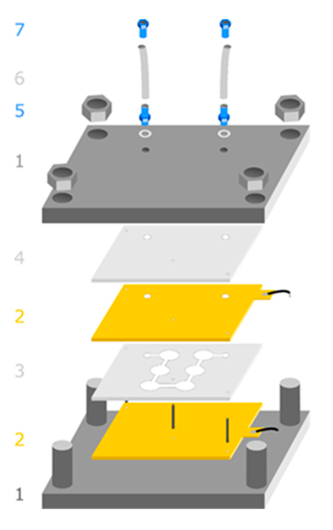
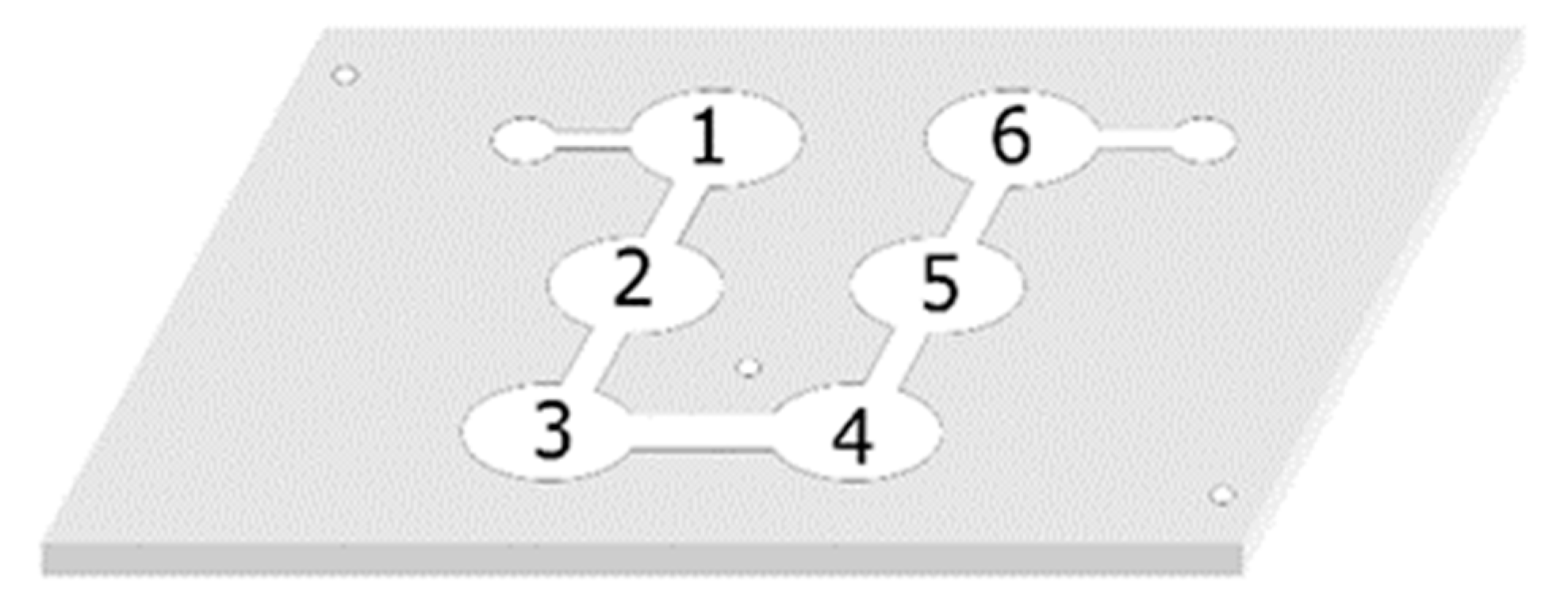
A set-up for the simultaneous production of multiple disk samples was developed, inspired by resin transfer molding, depicted in Figure 2. A silicone form for six disk samples of 20 mm diameter and 1.5 mm thickness (3 in Figure 2) was placed between two gold-coated electrodes (2 in Figure 2). Together with another layer of silicone (4 in Figure 2), which served as a sealant, the four layers were placed between two steel plates (1 in Figure 2). The outer plates were fitted with four nuts screwed together and used for clamping the structure. The inner arrangement was additionally fixed with 3 guiding pins, in order to prevent slipping or warping of the silicone form and thus avoiding the clogging of the narrow flowing channels between the disk molds.
After mounting the system together, two hose couplings (5 in Figure 2) were screwed on the top plate, each then connecting a feeding tube (6 in Figure 2) fastened with a tightening nut (7 in Figure 2). One of the hoses was closed with a clamp, the other one connected to a syringe with double sealing ring. With the syringe, a negative pressure is generated in the mold. Subsequently, the epoxy dispersion was mixed with the curing agent and, to avoid air bubbles in the samples, degassed under vacuum in a desiccator. The composition was then filled into a second syringe, connected to the feeding tube and fed to the cavity until it emerged from the other tube. The electrodes were connected to the voltage source through a temperature-resistant silicone coated cable. Finally, the complete mold was placed on top of an aluminum heating plate set to the desired curing temperature. In order to be able to remove the samples from the electrodes, a mold release agent had to be used. The standard mold release agent is usually either silicone- or polytetrafluoroethylene-based, and so in both cases electrically nonconductive. In order to evaluate the effect of the electrical conductivity of the interface between nanocomposite and electrode, experiments were performed with three different release agents: conductive silver paint, mechanical grease and carbon black filled grease.

2.4. Electric Field

A sinusoidal voltage of 60 Vpp at a frequency of 10 MHz was used to generate a sinusoidal alternating electric field strength of 400 Vpp/cm using a function generator Agilent 33250A and a high frequency power amplifier (Tabor 9260). The voltage and the frequency were chosen based on results presented in [22], where the procedure for electric field application is further described.

2.5. Characterization of Electrical Resistivity

For the investigation of electrical properties of samples produced with the three-roll mill, SWCNT/epoxy dispersions were used to produce bar-shaped samples (5 × 2 × 40 mm) in a silicone mold. For each experimental configuration, the electrical resistivity of six samples was measured using the four-point method. In this method, four contact points are used where the two outer ones lay an electrical current and the resulting voltage is measured by the inner ones.
Disk-shaped samples produced in the mold presented in Section 2.3 were characterized with electrochemical impedance spectroscopy in an IM6 workstation from Zahner-Elektrik GmbH (Kronach, Germany). This means that a measuring setup was used where a small sinusoidal potential of 1 mV with fixed frequency is applied to the sample, the response is measured, and the impedance computed at each frequency. The starting point frequency was set at 3 MHz and then it was gradually decreased to 500 mHz where the impedance assumes a constant value corresponding with acceptable approximation to the through-plane resistance.

3. Results

3.1. Dispersion

Two mixing modes were investigated in the three-roll mill:
  • Constant gap—The suspension was passed eight times with a fixed gap 1 of 15 μm (between the feed and center rolls—refer to 2 in Figure 2) and a gap 2 of 5 μm (between the center and apron rolls).
  • Regressive gap—Starting with a larger gap between rolls (60–20), and then every two passes halving the distance until reaching the physical limit used on constant gap mode, 15–5 μm.
The eight total suspension pass gaps are resumed in Table 1. To avoid an excessive promotion of rupture mechanism that could damage the aspect ratio of the nanoparticles, the speed on the apron roll was always set at 180 rpm.
Resistivity measurements for the two gap modes investigated are plotted in Figure 3. While the difference in first passes is still not perceivable, it reaches one order of magnitude after eight passes. Using the regressive gap mode seems to promote the lower electrical resistivity of SWCNT/epoxy composites for the same curing process parameters and without increasing the particle concentration. This is expected to result from the different agglomerate dispersion mechanisms [8], where erosion is fostered over rupture. The constant mode (gaps of 15–5 μm for each pass) imposes high shear forces to the bigger initial CNT agglomerates, promoting their rupture and, most likely, rupture of the nanotubes. On the other hand, starting with wider gaps in the regressive mode favors the erosion of the agglomerates over rupture, limiting the breakage of CNTs. A higher CNT aspect ratio for the same concentration seems to help the formation of more efficient secondary networks for electrons to flow across the bulk composite, by enhancing the chances of contact between adjacent particles.
Additionally, Figure 4 depicts the through-plane electrical resistivity of SWCNT/epoxy nanocomposites at different concentrations. For the lowest amount of SWCNTs (0.001 wt.%) the electrical resistivity was too high to be measured by the multimeter in resistance mode (limited to 50 MΩ) and hence the value presented corresponds to the multimeter range limit. From the figure it can be concluded that the percolation concentration lies between 0.001 wt.% and 0.005 wt.%. It can be observed that the through-plane resistivity for 0.1 wt.% SWCNT/epoxy disk-shaped samples in Figure 4 is substantially higher than the value in Figure 3, which corresponds to the in-plane resistivity measured with the four-point method.
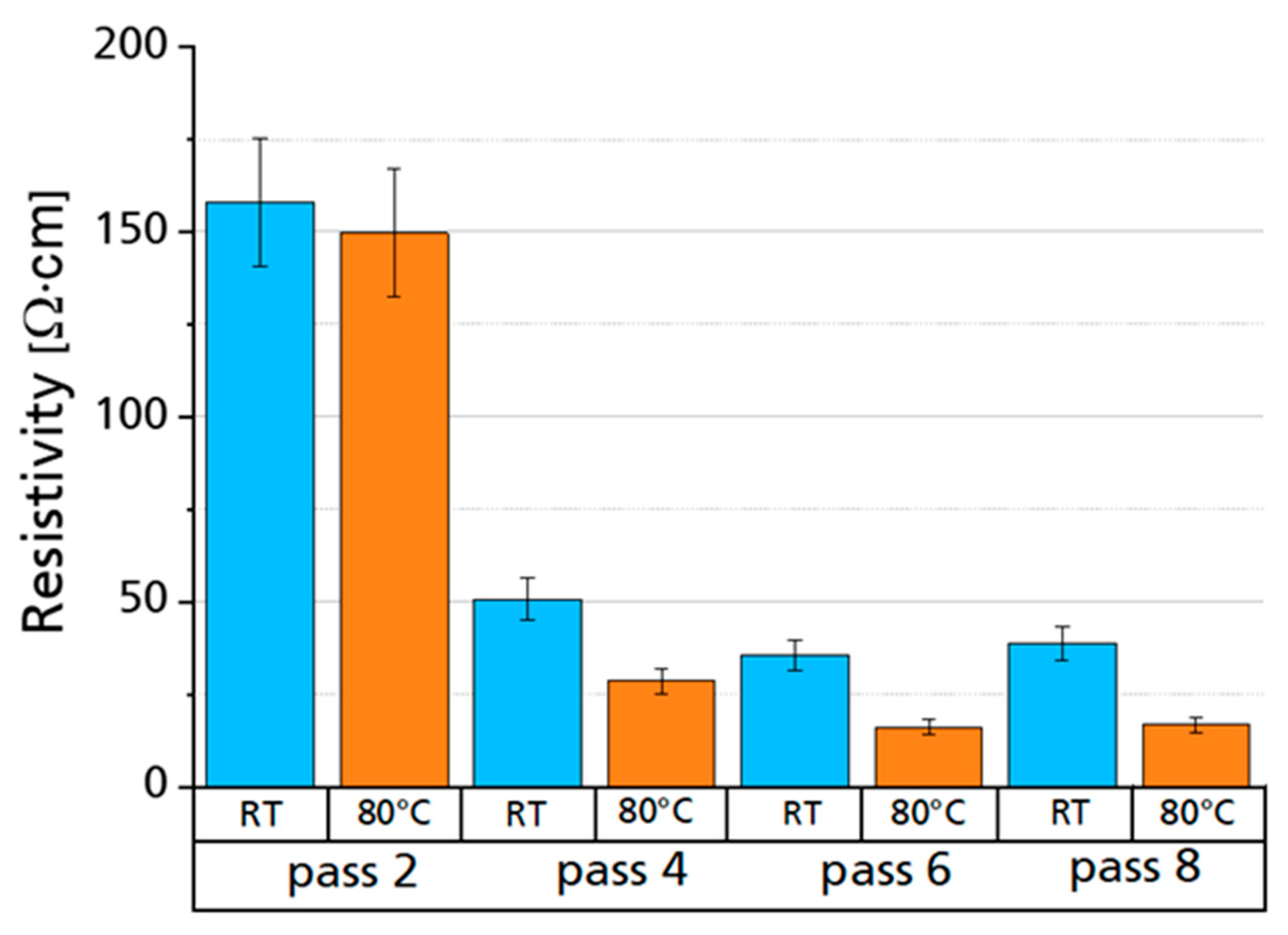
The influence of the curing temperature of the SWCNT/epoxy composites on the final electrical resistivity was investigated for samples collected after different numbers of passes in the three-roll mill. Specimens of SWCNT/epoxy at a concentration of 0.1 wt.% (mixed in constant gap mode) and at four different passes number were cured both at room temperature and heated up at 80 °C, accordingly also varying the overall curing time. The resistivity measurements are depicted in Figure 5. The beginning of a plateau is noticeable at pass number six, after which no improvements come from additional mixing in the three-roll mill. Moreover, by increasing the curing temperature, the electrical resistivity of the SWCNT/epoxy 0.1 wt.% composites appears to decrease around 50%. This is probably due to the fact that, at 80 °C, the resin matrix is less viscous than at room temperature, as it emerges from the rheological tests performed in [22]. A more liquid suspension provides less viscous resistance for the secondary agglomerates’ network formation, under Van der Waals forces or intentional applied dielectrophoresis (useful consideration for alignment experiments described further on in this paper, which in fact were performed at 80 °C).

3.2. Electric Fields

Dielectrophoresis experiments were performed with SWCNT/epoxy 0.01 wt.% composites. The main goal of this set-up was to produce multiple plate specimens simultaneously and with a shape defined by the silicone mold, which is a scalable process with potential application in industry. With every experiment, six disk samples were produced (20 mm diameter and 1.5 mm thickness), as can be seen in Figure 6.
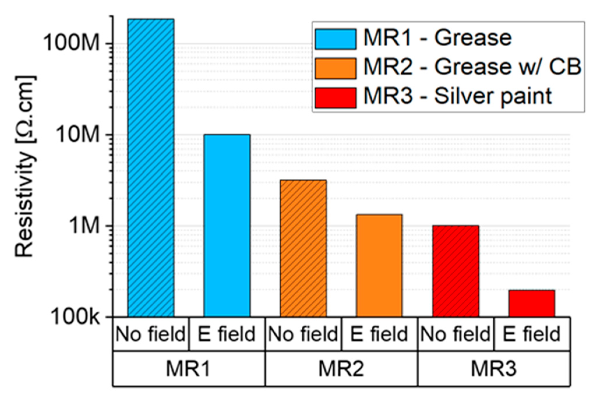
Furthermore, the influence of the use of distinct mold release agents was investigated. Figure 7 shows the resistivity values measured between the electrodes after the curing of SWCNT/epoxy 0.01 wt.% at 100 °C, with and without electric field. The first measurements presented here were done before opening the mold by connecting the electrodes to a multimeter after sample cool down. Therefore, the values represent the total resistivity of the material connecting the electrodes (six plates and the interconnections). A one order of magnitude decrease in the resistivity was generally measured.
However, a clear difference was noticeable when different mold release agents were used. With the most conductive one among the three, MR3 (silver paint), both the resistivity with and without electric field were two orders of magnitude lower than that of MR1. MR2 (intermediate conductivity) appeared to be in between the two and showed a minor difference between field and no field application. This is likely related to the contact resistance of the interface between the electrodes and the SWCNT/epoxy composite, which is presumably higher for MR1 and MR2.
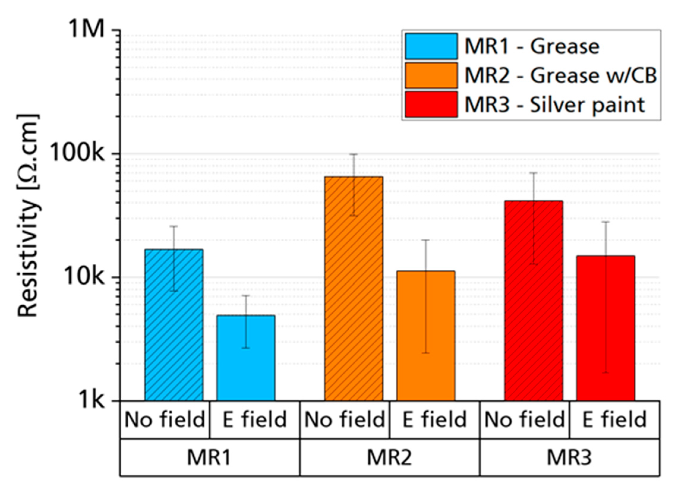
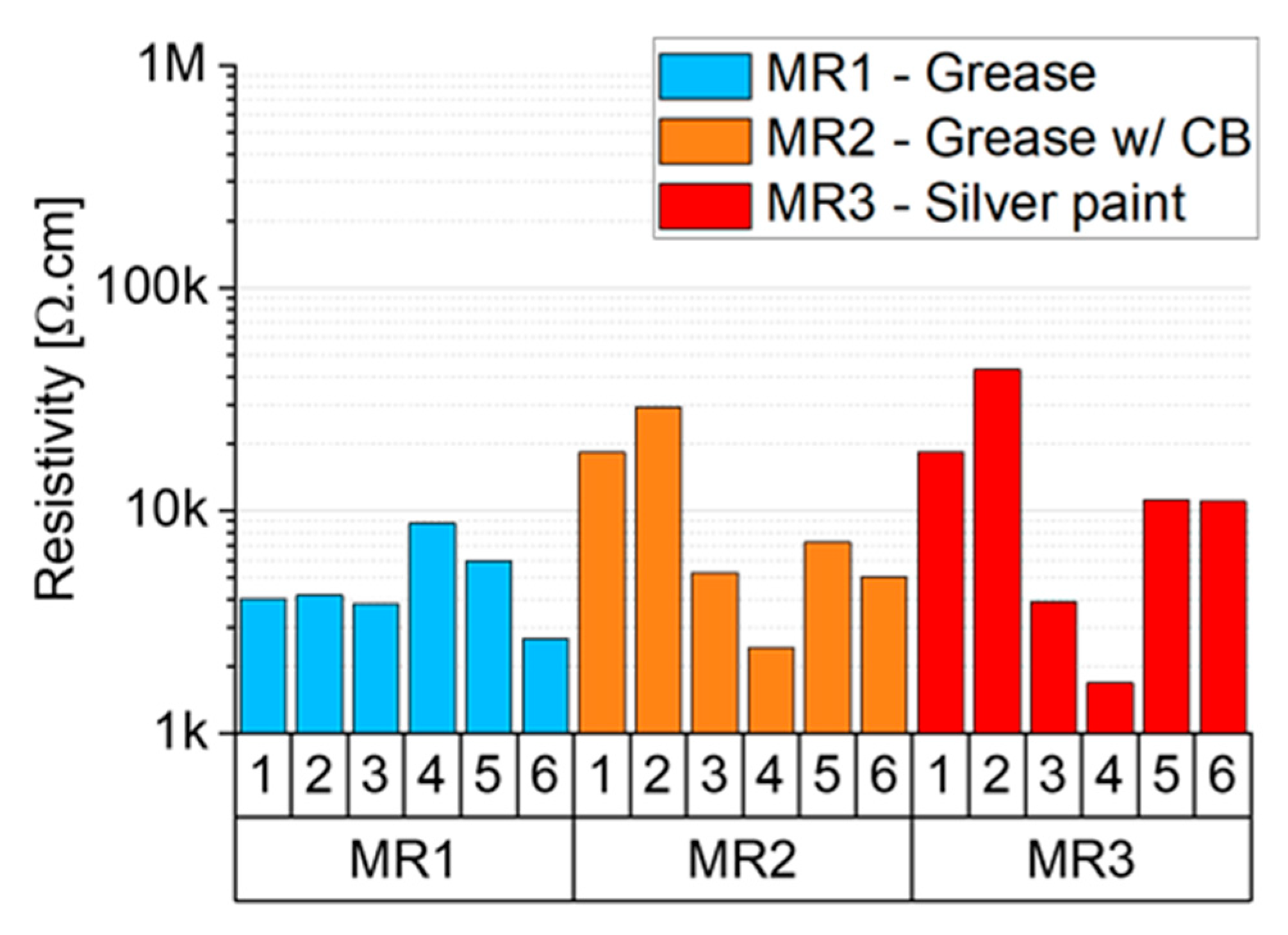
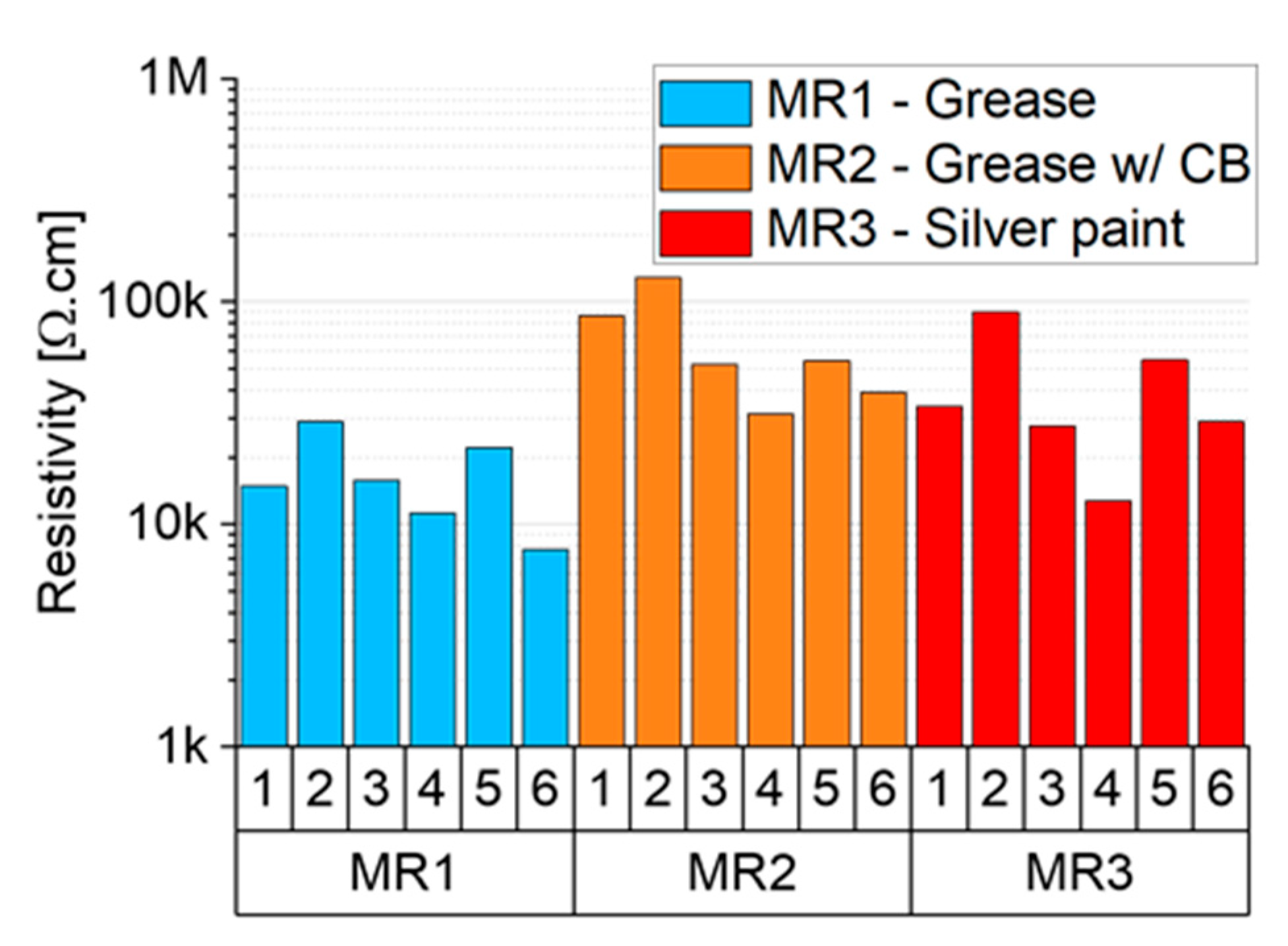
After specimen retrieval from the mold and thorough cleaning and gold sputtering of the individual disk samples for through-plane resistivity measurements, this property was evaluated. Figure 8 displays the average resistivity of individual samples corresponding to the results in Figure 7. This not only shows the difference between electric field and no field to be less pronounced than in Figure 7, but the resistivity values also show the opposite trend—MR3 leads to the highest average resistivity and MR1 to the lowest. This behavior can be explained by considering the properties of the individual samples after curing under the electric field, depicted in Figure 9 and Figure 10. In these graphs, the electrical resistivity of samples is plotted according to their fixed position in the mold, numbered from 1 to 6. For samples produced without electric field, the electrical resistivity of six samples for each mold release agent does not vary considerably (Figure 10). However, when an electric field is applied, as depicted in Figure 9, it is possible to observe that MR3 and MR2 show a great disparity of results between the six samples. MR3, for example, has specimen 4 with a resistivity of only 1.7 kΩ⋅cm, being the most conductive sample produced. However, samples 1, 2, 5 and 6 are all above 10 kΩ⋅cm.
A possible explanation for the measurements of total resistivity in Figure 7 is the following phenomenon: given the very low contact resistance of silver paint (MR3), more electrical current can flow between the electrodes. Due to this micro-current, the electric field propagates in the material across the sample thickness as new conductive paths are generated in the material due to CNT dielectrophoresis. However, as soon as one of the six samples becomes more conductive (e.g., sample 4 of MR3 in Figure 9), more and more current starts flowing only through it, since it offers less resistivity, and less current through the other samples (such as 1, 2, 5 and 6 of MR3 in Figure 9). This would explain the scatter in the resistivity values of samples MR2 and MR3 (Figure 9) and the resistivity measured in the closed mold presented in Figure 7. These results highlight the importance of the contact interface (more specifically its resistivity) between the electrodes and the composite for influencing the homogeneous electrical resistivity of SWCNT nanocomposites with electric fields.

4. Discussion and Conclusions

An optimized dispersion process that limits rupture mechanisms, hence presumably ensuring a high aspect ratio and well dispersed particles, proved to be fundamental when the aim is to decrease the electrical resistivity of thermoset nanocomposites. Once a good level of matrix infiltration, dispersion and distribution in the CNT agglomerates is obtained, it was found that heat application during the curing process further decreased the electrical resistivity of the nanocomposites. This is expected to be due to a reduction in the matrix viscosity at higher temperatures, allowing more mobility of the particles and hence leading to more contacts between them, as investigated in [22]. This proved to be beneficial when combined with the application of an electric field between the electrodes, leading to a reduction in resistivity of up to one order of magnitude compared to the samples cured without the field. As explored in [22], the clear alignment of CNTs due to the electric field was not observed in scanning electron microscope (SEM) images of sample fracture surfaces. Instead, the reduction in electrical resistivity was attributed to an electric-field-induced increase in contact points between the nanoparticles. This possibility was investigated in [22] with finite element simulations of CNT networks in epoxy at different concentrations.
Furthermore, an RTM set-up for applying electric fields to nanocomposites during curing has been developed and successfully tested. When applying electric fields to the nanocomposite during curing, the conductivity of the interface between the electrodes and the nanocomposite resin was shown to play a crucial role in determining the final resistivity of the bulk materials produced. A highly conductive interface (MR3) promoted more inhomogeneous samples, leading to pronounced changes in the resistivity at a local level (significant differences between six samples produced simultaneously). On the other hand, a highly resistive interface (MR1) prevented such local differences and resulted in a smaller average resistivity in the samples produced. The use of a nonconductive mold release agent therefore seems more suitable for a scalable industrial process since it leads to composites with more homogeneous electrical properties.
Overall, the use of an electric field during processing shows promising results for enhancing the through-plane electrical conductivity of polymer composites with carbon-based nanoparticles by influencing the structure of the conductive network during the processing step. Such technology would reduce the amount of CNTs necessary to achieve similar electrical properties, hence allowing a cheaper production of composites with a broad range of industrial applications (e.g., sensors, batteries, electrical heating technologies). The aim of further research in this topic should be to understand the impact of the type of carbon nanoparticles used (or a combination of particles with different size scales), the effect of stronger electric fields with lower particle concentrations and limitations arising from matrix viscosity.

Author Contributions

Conceptualization, M.V.C.M., M.M., C.H. and F.H.; Data curation, M.V.C.M., M.M. and N.S.; Funding acquisition, C.H.; Investigation, M.V.C.M., M.M. and N.S.; Methodology, M.V.C.M. and C.H.; Supervision, C.H. and F.H.; Writing—original draft, M.V.C.M. and M.M.; Writing—review and editing, M.V.C.M., M.M., N.S., C.H. and F.H. All authors have read and agreed to the published version of the manuscript.

Funding

This research has received funding from the European Union’s Horizon 2020 research and innovation program under the Marie Skłodowska-Curie Grant Agreement no. 642890 (TheLink, www.thelink-project.eu).

Conflicts of Interest

The authors declare no conflict of interest.

References

  1. Kaur, G.; Adhikari, R.; Cass, P.; Bown, M.; Gunatillake, P. Electrically conductive polymers and composites for biomedical applications. RSC Adv. 2015, 5, 37553–37567. [Google Scholar] [CrossRef]
  2. Yeetsorn, R.; Fowler, M.W.; Tzoganakis, C.A. Review of Thermoplastic Composites for Bipolar Plate Materials in PEM Fuel Cells. In Nanocomposites with Unique Properties and Applications in Medicine and Industry; InTech: London, UK, 2011. [Google Scholar]
  3. Lan, Y.C.; Wang, Y.; Ren, Z.F. Physics and applications of aligned carbon nanotubes. Adv. Phys. 2011, 60, 553–678. [Google Scholar]
  4. Zeng, Z.; Jin, H.; Chen, M.; Li, W.; Zhou, L.; Zhang, Z. Lightweight and anisotropic porous mwcnt/wpu composites for ultrahigh performance electromagnetic interference shielding. Adv. Funct. Mater. 2016, 26, 303–310. [Google Scholar] [CrossRef]
  5. Alig, I.; Pötschke, P.; Lellinger, D.; Skipa, T.; Pegel, S.; Kasaliwal, G.R.; Villmow, T. Establishment, morphology and properties of carbon nanotube networks in polymer melts. Polymer 2012, 53, 4–28. [Google Scholar] [CrossRef]
  6. Bauhofer, W.; Kovacs, J.Z. A review and analysis of electrical percolation in carbon nanotube polymer composites. Compos. Sci. Technol. 2009, 69, 1486–1498. [Google Scholar] [CrossRef]
  7. Krause, B.; Potschke, P.; Haussler, L. Melt mixed SWCNT-polypropylene composites with very low electrical percolation. Polymer 2016, 98, 45–50. [Google Scholar] [CrossRef]
  8. Kasaliwal, G.R.; Göldel, A.; Pötschke, P.; Heinrich, G. Influences of polymer matrix melt viscosity and molecular weight on MWCNT agglomerate dispersion. Polymer 2011, 52, 1027–1036. [Google Scholar] [CrossRef]
  9. Kasaliwal, G.R.; Pegel, S.; Göldel, A.; Pötschke Petra, P.; Heinrich, G. Analysis of agglomerate dispersion mechanisms of multiwalled carbon nanotubes during melt mixing in polycarbonate. Polymer 2010, 51, 2708–2720. [Google Scholar] [CrossRef]
  10. Sandler, J.K.W.; Kirk, J.E.; Kinloch, I.A.; Shaffer, M.S.P.; Windle, A.H. Ultra-low electrical percolation threshold in carbon-nanotube-epoxy composites. Polymer 2003, 44, 5893–5899. [Google Scholar] [CrossRef]
  11. Peng, B.; Locascio, M.; Zapol, P.; Li, S.; Mielke, S.L.; Schatz, G.C. Measurements of near-ultimate strength for multiwalled carbon nanotubes and irradiation-induced crosslinking improvements. Nat. Nanotechnol. 2008, 3, 626–631. [Google Scholar] [CrossRef] [PubMed]
  12. Iosif, D.; Rosca, S.; Hoa, V. Highly conductive multiwall carbon nanotube and epoxy composites produced by three-roll milling. Carbon 2009, 47, 1958–1968. [Google Scholar]
  13. Yamamoto, K.; Akita, S.; Nakayama, Y. Orientation of carbon nanotubes using electrophoresis. Jpn. J. Appl. Phys. 1996, 2, L917. [Google Scholar] [CrossRef]
  14. Yamamoto, K.; Akita, S.; Nakayama, Y. Orientation and purification of carbon nanotubes using ac electrophoresis. J. Phys. D Appl. Phys. 1998, 31, L34. [Google Scholar] [CrossRef]
  15. Oliva-Avilés, A.I.; Avilés, F.; Sosa, V.; Oliva, A.I.; Gamboa, F. Dynamics of carbon nanotube alignment by electric fields. Nanotechnology 2012, 23, 465710. [Google Scholar] [CrossRef]
  16. Martin, C.A.; Sandler, J.K.W.; Windle, A.H.; Schwarz, M.K.; Bauhofer, W.; Schulte, K.; Shaffer, M.S.P. Electric field-induced aligned multi-wall carbon nanotube networks in epoxy composites. Polymer 2005, 46, 877–886. [Google Scholar] [CrossRef]
  17. Li, J.; Zhang, Q.; Peng, N.; Zhu, Q. Manipulation of carbon nanotubes using AC dielectrophoresis. Appl. Phys. Lett. 2005, 86, 1–3. [Google Scholar] [CrossRef]
  18. Park, C.; Wilkinson, J.; Banda, S.; Ounaies, Z.; Wise, K.E.; Sauti, G.; Lillehei, P.T.; Harrison, J.S. Aligned single-wall carbon nanotube polymer composites using an electric field. J. Polym. Sci. Polym. Phys. Ed. 2006, 44, 1751–1762. [Google Scholar] [CrossRef]
  19. Cheng, Q.F.; Wang, J.P.; Wen, J.J.; Liu, C.H.; Jiang, K.L.; Li, Q.Q.; Fan, S.S. Carbon nanotube/epoxy composites fabricated by resin transfer molding. Carbon 2010, 48, 260–266. [Google Scholar] [CrossRef]
  20. Olowojoba, G.; Sathyanarayana, S.; Caglar, B.; Kiss-Pataki, B.; Mikonsaari, I.; Hübner, C.; Elsner, P. Influence of process parameters on the morphology, rheological and dielectric properties of threeroll-milled multiwalled carbon nanotube/epoxy suspensions. Polymer 2013, 54, 188–198. [Google Scholar] [CrossRef]
  21. Olowojoba, G.; Sathyanarayana, S.; Caglar, B.; Mikonsaari, I.; Hübner, C.; Elsner, P. Influence of processing temperature, carbon nanotube agglomerate bulk density and functionalization on the dielectric and morphological properties of carbon nanotube / epoxy suspensions. In Proceedings of the Polymer Processing Society 29th Annual Meeting PPS-29, Nuremberg, Germany, 15–19 July 2013. [Google Scholar]
  22. Morais, M.V.C.; Oliva-Avilés, A.I.; Matos, M.A.S.; Tagarielli, V.L.; Pinho, S.T.; Hübner, C.; Henning, F. On the effect of electric field application during the curing process on the electrical conductivity of single-walled carbon nanotubes–epoxy composites. Carbon 2019, 150, 153–167. [Google Scholar] [CrossRef]
Figure 1. Three-roll mill schematic: suspension is fed between the first two rolls, passes through gap 1 and gap 2 and is finally collected completing a “pass” cycle.
Jcs 04 00114 g001
Figure 2. Exploded view of the mold used to apply the electric field during resin curing: six disc samples are produced at a time.
Jcs 04 00114 g002
Figure 3. Electrical resistivity of SWCNT/epoxy 0.1 wt.% bar-shaped samples produced with two gap-modes in the three-roll mill and measured with the four-point method.
Jcs 04 00114 g003
Figure 4. Through-plane electrical resistivity of SWCNT/epoxy as a function of particle concentration for eight passes.
Jcs 04 00114 g004
Figure 5. SWCNT/epoxy 0.1 wt.%—influence of curing temperature on electrical resistivity at different passes.
Jcs 04 00114 g005
Figure 6. Silicon mold (corresponding to point 3 in Figure 2), which allows for the production of six discs of 20 mm diameter per 1.5 mm thickness.
Jcs 04 00114 g006
Figure 7. Impact of mold release agent (MR1,2,3) on plate resistivity measured at the electrodes (after cure) for SWCNT/epoxy 0.01 wt.% composites.
Jcs 04 00114 g007
Figure 8. Impact of mold release agent on single disc average resistivity of SWCNT/epoxy 0.01 wt.%.
Jcs 04 00114 g008
Figure 9. With electric field: Impact of mold release agent on resistivity of SWCNT/epoxy 0.01 wt.% individual samples cured at 100 °C.
Jcs 04 00114 g009
Figure 10. Without electric field: Impact of mold release agent on resistivity of SWCNT/epoxy 0.01 wt.% individual samples cured at 100 °C.
Jcs 04 00114 g010
Table 1. Three-roll mill mixing modes investigated.
Pass12345678
Constant gap (µm)15–515–515–515–515–515–515–515–5
Regressive gap (µm)60–2060–2030–1030–1015–515–515–515–5