Article

Damage Analysis of Thermoplastic Composites with Embedded Metal Inserts Using In Situ Computed Tomography

Institute of Lightweight Engineering and Polymer Technology (ILK), Technische Universität Dresden, Holbeinstraße 3, 01307 Dresden, Germany
*
Author to whom correspondence should be addressed.
J. Compos. Sci. 2022, 6(10), 287; https://doi.org/10.3390/jcs6100287
Submission received: 31 August 2022 / Revised: 21 September 2022 / Accepted: 26 September 2022 / Published: 29 September 2022
(This article belongs to the Special Issue Progress in Polymer Composites, Volume II)

Abstract

:
Thermoplastic composites (TPCs) are predestined for use in lightweight structures, for example, in automotive engineering, due to their good specific mechanical properties. In many areas of lightweight design, the use of metal inserts for load introduction into composite structures has become established. The inserts can be embedded during composite manufacturing without fibre damage. The technology is based on the concept of moulding holes with a pin tool and simultaneously placing the insert in the moulded hole. The embedding process results in a complex material structure in the joining zone with inhomogeneous three-dimensional fibre orientation and locally varying fibre content. The local material structure has a significant influence on the mechanical behaviour of the joining zone. For this reason, in situ computed tomography (CT) analyses are conducted in this work for a better understanding of the damage behaviour in the joining zone. In situ CT push-out tests were carried in the two thickness directions of along and opposed to the direction of the embedding process. The characteristic local material structure in the joining zone led to direction-dependent damage behaviour based on different failure modes.

1. Introduction

Thermoplastic composites (TPCs) have much potential for the large-scale production of lightweight components. Reasons for this include the good specific mechanical properties and established manufacturing processes [1]. Embedding metal inserts into composites is well-known as a reliable and efficient joining technique in many areas of lightweight design [2], but also in various fields of application such as fine equipment or automation, and handling industries inserts are commonly used for load application purposes. In addition, inserts offer the possibility of providing composite structures with functional interfaces, such as electrical contact points or media feedthroughs, and thus expand their application potential. For bolted joints, metal inserts can reduce stress concentrations in the composite around the hole, increasing the joint strength [3,4,5].
There are two basic approaches for integrating metal inserts into composites. They can be inserted into a separate downstream process step or during a part manufacturing process. For downstream joining, the metal inserts are typically inserted and fixed into a previously cut hole, for example, with screwing [3] or bonding processes [6]. In the case of composites with a thermoset matrix, inserts are often integrated during part manufacturing, for instance, in the resin transfer moulding (RTM) process [7]. Thereby, the reinforcing structure can be reorientated locally around the insert without fibre damage, as shown by Wilkening et al. [8], Ferret et al. [9], and Gebhardt and Fleischer [10]. With TPC, the embedding of inserts during component manufacture is possible. For instance, this can be performed with process-integrated embedding on the basis of the principle of moulding holes described by Kupfer et al. [11]. In this process, the reinforcing fibres are reorientated with a tapered pin tool in the plasticised state of the TPC instead of cutting them, for example, by drilling [12].
The embedding of inserts into TPC sheets with a pin tool leads to a local complex material structure with an inhomogeneous three-dimensional fibre orientation and locally varying fibre content [13]. This local material structure in the joining zone influences the load bearing behaviour [14]. Quasistatic out-of plane loading tests demonstrated that both the failure forces and the failure behaviour depended on the testing direction (along and opposed to the direction of the embedding process) [15]. To identify the different damage modes and locations in the joining zone and the chronology of appearance, in situ CT analyses of push-out tests are performed in this work.
For in situ characterisation, a test rig is combined with a CT scanner to perform the experiments, e.g., load-bearing tests. Recently, the in situ CT method was used to investigate various joining zones under loading, e.g., clinched lap joints of aluminium [16], adhesively bonded riveted lap joints of thermoset composite and aluminium [17], or in thermoset composite embedded inserts [18]. Compared to ex situ test methods (e.g., microsection analyses or conventional CT), in situ CT can be used to obtain detailed information regarding the damage chronology in a joining zone during testing. The main disadvantages of ex situ analyses, such as resetting of elastic deformations and the resulting crack closure effects, thus do not occur with the in situ method.

2. Materials and Methods

2.1. Material Specification

The investigations were performed on TPC sheets of glass-fibre-reinforced polypropylene (GF/PP). In an autoclave, unidirectional tapes (Celstran® CFR-TP PP-GF70) as semifinished products were processed (200 °C, 6 bar) into sheets with a laminate structure of [(0°/90°)8]s. The resulting TPC sheets were characterised by thickness of approximately 4.3 mm and fibre volume content of approximately 45%. These sheets were cut into 100 × 100 mm specimens into which the aluminium inserts were embedded.

2.2. Specimen Preparation

The process of embedding inserts into TPC is schematically illustrated in Figure 1. First, the TPC sheet was warmed above the melting temperature of the polymer matrix (by an infrared heating device) and then transferred into an open compression mould. After closing the tempered compression mould (a), a two-part pin tool (consisting of pin retainer and tapered pin) was moved forward, forming a hole by displacing the reinforcing fibres and the still molten matrix (b). The pin tool was equipped with the insert, which was positioned flush with the composites surface. After the pin movement, the squeezed-out material was recompressed with an annular counterpunch (c), filling the undercut of the insert with fibres and the matrix material. The embedding process (steps (b) and (c)) took less than 1 s . Subsequent to cooling and solidification, the shaped TPC part could be demoulded (d).
The test specimens were manufactured with a pilot rig on a laboratory scale including an infrared heating device and a tempered steel mould with vertical flash face (Figure 2). The pin tool and counterpunch were pneumatically actuated. The manufacturing parameters are summarised in Table 1. Prior to the in situ CT tests, the specimens were cut into 40 × 40 mm with the inserts positioned centrally in the specimen.
The inserts were rotationally symmetric, and the height of the insert corresponded to the thickness of the TPC sheet so that they were flush with the laminate surface after embedding (Figure 3).

2.3. Test Setup and Procedure

To analyse the local material structure in the joining zone resulting from the embedding process, a conventional CT scan was carried out. Therefore, one-quarter of the specimen was examined ( 20 × 20 mm). By cutting the sample, the insert was removed, so that the specimen could be scanned without the metal part to reduce the risk of artefacts and improve scan quality. For this analysis, CT-system V|TOME|X L450CT (from GE Sensing & Inspection Technologies GmbH) with a 300 kV microfocus X-ray tube was used. The scanning parameters are summarised in Table 2.
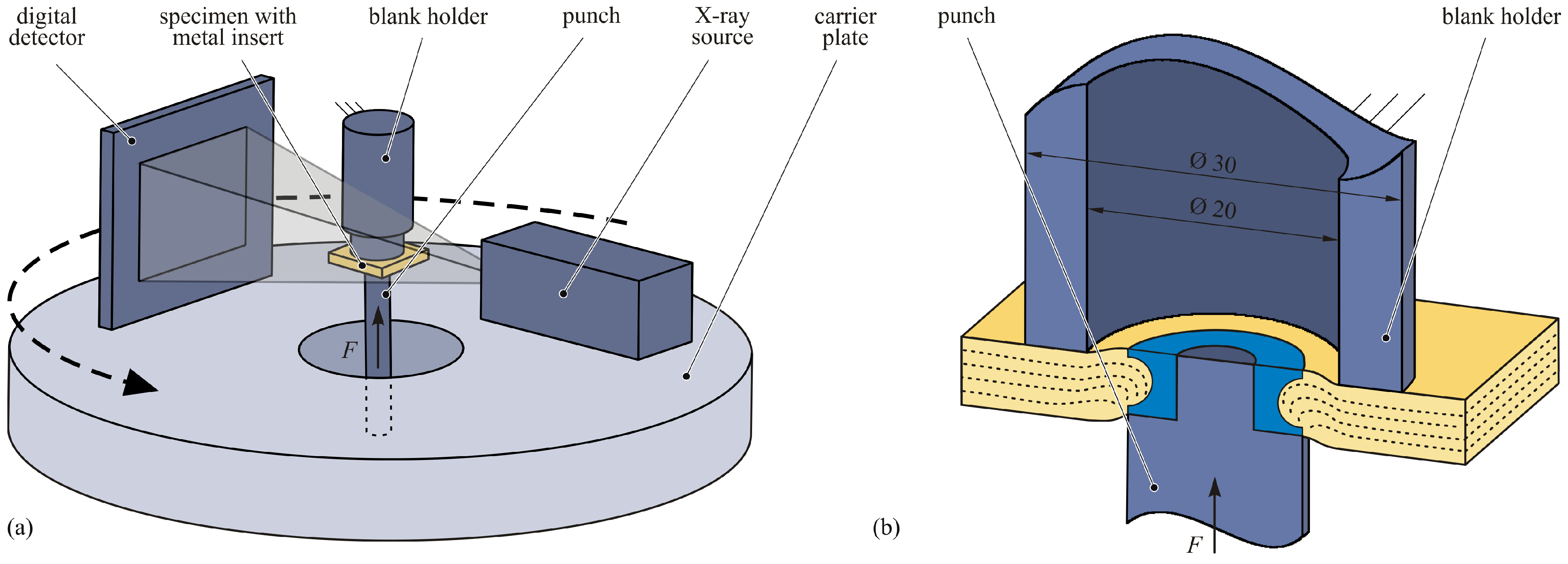
The in situ CT push-out tests were performed on a CT device FCTS 160-IS (from Finetec FineFocus Technologies GmbH, Garbsen, Germany) consisting of a X-ray source FORE 160.01C TT (160 kV, 1 mA, 80 W) and a flat panel detector (3200 pixel × 2300 pixel, 14 bit). The X-ray source and X-ray detector were mounted onto a circular carrier plate rotating around the push-out test setup during the scanning phase (Figure 4a).
The specimen was positioned between a blank holder and a punch in the in situ testing machine based on a Zwick Z250 (ZwickRoell GmbH & Co. KG, Ulm, Germany). Both the blank holder and punch were produced with aluminium to achieve the low attenuation caused by the test setup for good image quality and reduced artefact formation in the CT scans. The lower traverse moved with a constant crosshead velocity of 1 mm/min, pressing the punch against the insert (Figure 4b).
In order to identify the different failure modes and locations in the joining zone, in situ CT analyses of the push-out tests were performed in both thickness directions, along and opposed to the direction of the embedding process (positive and negative z directions; see Figure 3a). To analyse the damage chronology, different displacement levels were examined by CT, whereby the crossbeam remained at constant displacement (cf. Figure 5a). Taking into account the time-dependent material behaviour of the TPC, the scan started after a relaxation phase of 60 min when a state of quasiequilibrium had been reached (cf. Figure 5b). The CT scanning parameters are summarised in Table 3. In order to obtain high-quality reconstructions and reduce measuring inaccuracies due to the transient heating of the X-ray source or thermal expansion of the specimen, according to the findings in [19], the total scan time was reduced to the minimum. The number of individual scans was reduced to 1440 (4 per 1°), and the exposure time was set to 0.5   s .

3. Results and Discussion

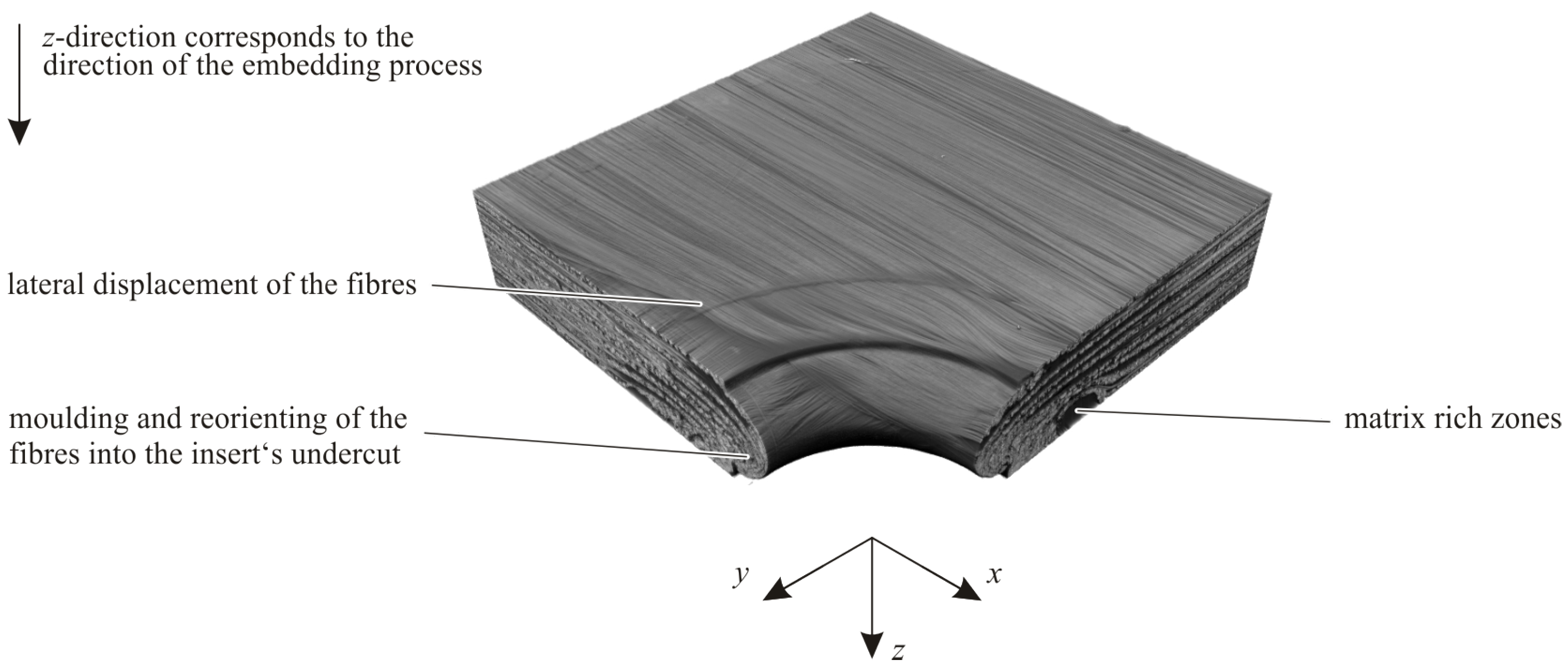
The embedding process lead to a complex material structure in the joining zone. On the one hand, the fibres were laterally shifted in the laminate plane by the pin movement (Figure 6). On the other hand, the fibres were moulded into the undercut of the insert and reorientateed in thickness direction. This also resulted in matrix-rich zones without any fibres. Accordingly, the resulting material structure was characterised by an inhomogeneous three-dimensional fibre orientation and locally varying fibre content (see also [13]). Thus, despite the fact that the insert and nitial laminate structure were symmetrical to the laminate midplane, there was a significantly nonsymmetrical material structure in the area around the insert resulting from the embedding process.
In order to analyse the influence of this local material structure on the deformation and damage behaviour, the in situ CT push-out tests were evaluated exemplarily on three displacement stages: 0.3 , 1.0 , and 2.5 , and 3 m m (Figure 5a). These displacement levels were below the maximal displacement and the resulting total failure of the joint. In the positive z direction, the maximal load of approximately 8.1 kN was measured, whereas in the opposite loading direction, the maximal force was only approximately 4.3 kN (Figure 5b). This observation is consistent with [15].
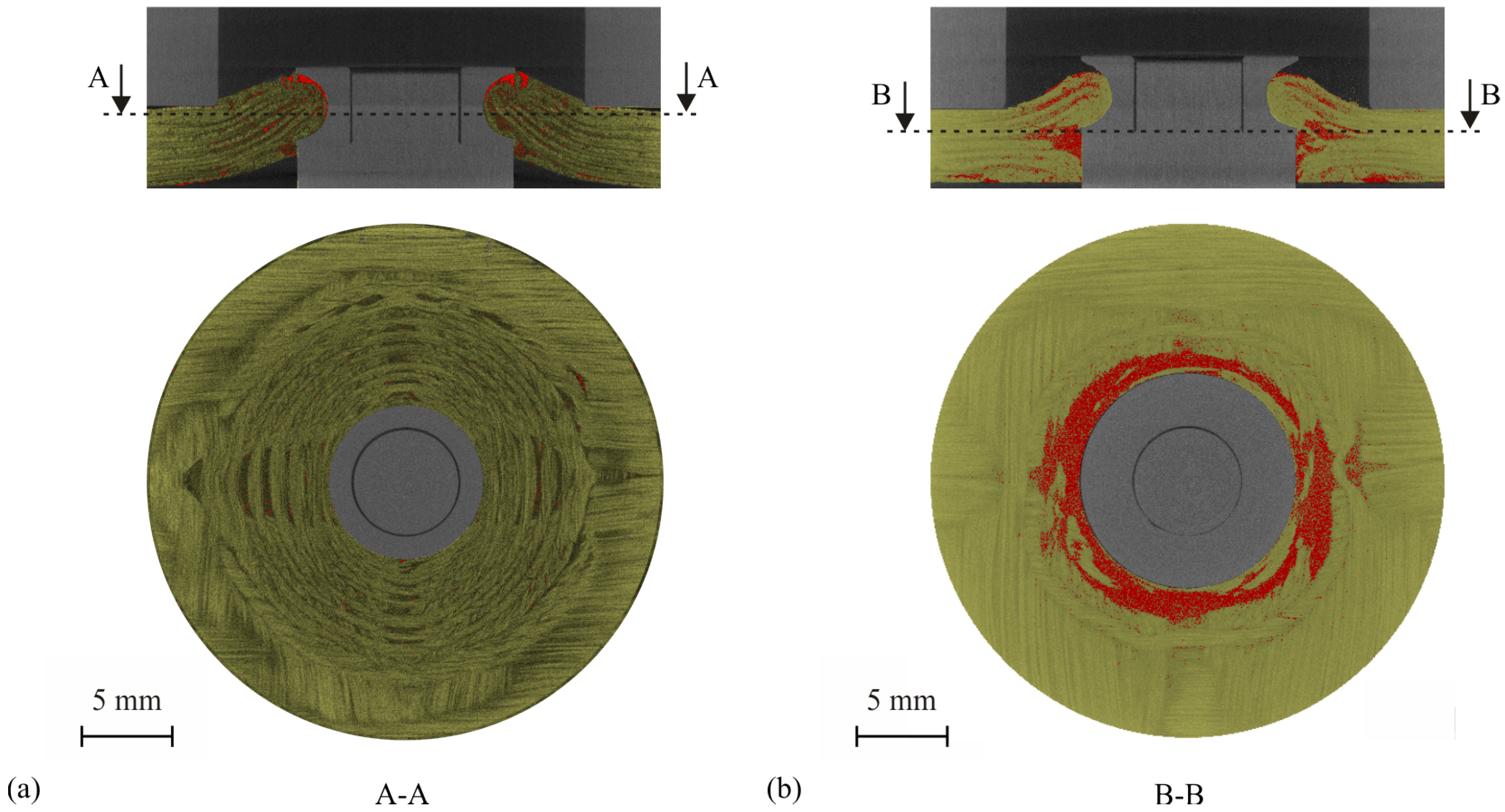
The results of the in situ CT analyses are shown in Figure 7. In these cross-sectional images, it is evident that the two testing directions exhibited different deformation and damage behaviours. In the positive z direction, the TPC sheet was strongly bent. However, the composite remained intact in large areas (Figure 8a), with some cracks appearing in the TPC near the insert. The insert pressed mainly onto the fibres moulded into the undercut (see Figure 3c). In the negative z direction, however, the TPC sheet was hardly bent on the punch side. The insert was pressed through the composite, resulting in shear failure. Since the insert could hardly be supported by the moulded-in fibres, tensile failure of the matrix occurred. This resulted in large-area inter laminar failures (delaminations) and a "fanning out" of the laminate in the entire perimeter of the insert (Figure 8b). Deformations of the insert could not be detected for any of the two testing directions.

4. Conclusions and Outlook

The process-integrated embedding of inserts into TPC resulted in a complex material structure in the joining zone with inhomogeneous three-dimensional fibre orientation and locally varying fibre content. The local material structure had a significant influence on the mechanical behaviour of the joining zone. In this work, in situ CT push-out tests were performed in the two thickness directions of along and opposed to the direction of the embedding process. High-quality CT scans could be achieved by using aluminium for the inserts and the test equipment (blank holder and punch). The maximal push-out force in the direction of the embedding process (positive z direction) was almost twice as high as that in the opposite direction (negative z direction). Accordingly, the deformation and damage behaviour for the two testing directions were also significantly different. Whereas for the positive z direction the TPC sheet was strongly bent, and only local cracks were detectable, in the negative z direction, the insert was pressed through the composite, resulting in the shear failure of the TPC, and large areas with delaminations and a “fanning out” of the laminate. This difference in the damage behaviour explains why the load-bearing capacity differed so much for the two testing directions. For further investigations, the local strain field within the TPC specimen could be a valuable input for a deeper understanding of deformation and damage behaviour of TPCs with embedded inserts. Therefore, a detailed combination of volumetric digital image correlation (V-DIC) and high-resolution CT scans, as presented in [20], would be worthwhile. This also includes the exact consideration of the error variables caused by the testing and scanning process, which has an effect on the reconstruction by means of V-DIC, and thereby affects the interpretation of local strain fields and the evaluation of the material behaviour, as reported in [19]. The extension of the investigations to the deformation and damage behaviour of the inserts using combined V-DIC and in situ CT analysis, as shown in [21] for copper materials, is also an aspect for future research. In summary, it is necessary to develop a complete understanding of the deformation and failure behaviour of both composite and embedded inserts. This would also answer further questions, for example, the residual load-bearing capacity of the embedded inserts after a predamage event or an estimate of the maximal permissible operating time.

Author Contributions

Conceptualization, J.T. and R.F.; experimental investigations, J.T. and R.F.; writing and visualization, J.T. and R.F.; writing—review, R.K. and M.G.; funding acquisition, J.T., R.K. and M.G.; supervision, R.K. and M.G.; project administration, M.G.; All authors have read and agreed to the published version of the manuscript.

Funding

This research was funded by the Deutsche Forschungsgemeinschaft (DFG, German Research Foundation) within the scope of the research project “Simulation-assisted development of material-, load- and process-specific inserts for thermoplastic composites” (project ID: 408132410).

Data Availability Statement

Not applicable.

Conflicts of Interest

The authors declare no conflict of interest.

Abbreviations

The following abbreviations are used in this manuscript:
MDPIMultidisciplinary Digital Publishing Institute
CTComputed tomography
GFGlass fibre
PPPolypropylene
TPCsThermoplastic composites
UDUnidirectional
V-DICVolumetric digital image correlation

References

  1. Behrens, B.-A.; Raatz, A.; Hübner, S.; Bonk, C.; Bohne, F.; Bruns, C.; Micke-Camuz, M. Automated Stamp Forming of Continuous Fiber Reinforced Thermoplastics for Complex Shell Geometries. Procedia CIRP 2017, 66, 113–118. [Google Scholar] [CrossRef]
  2. Herwig, A.; Horst, P.; Schmidt, C.; Pottmeyer, F.; Weidenmann, K.A. Design and mechanical characterisation of a layer wise build AFP insert in comparison to a conventional solution. Prod. Eng. 2018, 12, 121–130. [Google Scholar] [CrossRef]
  3. Mara, V.; Haghani, R.; Al-Emrani, M. Improving the performance of bolted joints in composite structures using metal inserts. J. Compos. Mater. 2016, 50, 3001–3018. [Google Scholar] [CrossRef]
  4. Herrera-Franco, P.J.; Cloud, G.L. Strain-Relief Inserts for Composite Fasteners—An Experimental Study. J. Compos. Mater. 1992, 26, 751–768. [Google Scholar] [CrossRef]
  5. Rispler, A.R.; Steven, G.P.; Tong, L. Photoelastic evaluation of metallic inserts of optimised shape. Compos. Sci. Technol. 2000, 60, 95–106. [Google Scholar] [CrossRef]
  6. Camanho, P.P.; Matthews, F.L. Bonded metallic inserts for bolted joints in composite laminates. Proc. Instn. Mech. Engrs. Part L 2000, 214, 33–44. [Google Scholar] [CrossRef]
  7. Camanho, P.P.; Tavares, C.; de Oliveira, R.; Marques, A.; Ferreira, A. Increasing the efficiency of composite single-shear lap joints using bonded inserts. Compos. Part B 2005, 36, 372–383. [Google Scholar] [CrossRef]
  8. Wilkening, J.; Pottmeyer, F.; Weidenmann, K.A. Research on the interfering effect of metal inserts in carbon fiber reinforced plastics manufactured by the RTM process. In Proceedings of the 17th European Conference on Composite Materials (ECCM17), Munich, Germany, 26–30 June 2016. [Google Scholar]
  9. Ferret, B.; Anduze, M.; Nardari, C. Metal insters in structural composite materials manufactured by RTM. Compos. Part A 1998, 29, 693–700. [Google Scholar] [CrossRef]
  10. Gebhardt, J.; Fleischer, J. Experimental investigation and performance enhancement of inserts in composite parts. Procedia CIRP 2014, 23, 7–12. [Google Scholar] [CrossRef]
  11. Hufenbach, W.; Adam, F.; Kupfer, R. A novel textile-adapted notching technology for bolted joints in textile-reinforced thermoplastic composites. In Proceedings of the 14th European Conference on Composite Materials (ECCM14), Budapest, Hungary, 6–7 June 2010. Paper ID 461. [Google Scholar]
  12. Hufenbach, W.; Gottwald, R.; Kupfer, R. Bolted Joints with Moulded Holes for Textile Thermoplastic Composites. In Proceedings of the 18th International Conference on Composite Materials, Jeju, Korea, 21–26 August 2011. [Google Scholar]
  13. Troschitz, J.; Gröger, B.; Würfel, V.; Kupfer, R.; Gude, M. Joining Processes for Fibre-Reinforced Thermoplastics: Phenomena and Characterisation. Materials 2022, 15, 5454. [Google Scholar] [CrossRef] [PubMed]
  14. Troschitz, J.; Kupfer, R.; Gude, M. Experimental investigation of the load bearing capacity of inserts embedded in thermoplastic composites. In Proceedings of the 4th International Conference Hybrid 2020—Materials & Structures, Online, 28–29 April 2020; pp. 249–254. [Google Scholar]
  15. Troschitz, J.; Kupfer, R.; Gude, M. Process-integrated embedding of metal inserts in continuous fibre reinforced thermoplastics. Procedia CIRP 2019, 85, 84–89. [Google Scholar] [CrossRef]
  16. Köhler, D.; Kupfer, R.; Troschitz, J.; Gude, M. In Situ Computed Tomography—Analysis of a Single-Lap Shear Test with Clinch Points. Materials 2021, 14, 1859. [Google Scholar] [CrossRef] [PubMed]
  17. Füßel, R.; Gude, M.; Mertel, A. In-situ X-ray computed tomography analysis of adhesively bonded riveted lap joints. In Proceedings of the 17th European Conference on Composite Materials, Munich, Germany, 26–30 June 2016. [Google Scholar]
  18. Pottmeyer, F.; Bittner, J.; Pinter, P.; Weidenmann, K.A. In-Situ CT Damage Analysis of Metal Inserts Embedded in Carbon Fiber-Reinforced Plastics. Exp. Mech. 2017, 57, 1411–1422. [Google Scholar] [CrossRef]
  19. Croom, B.P.; Burden, D.; Jin, H.; Vonk, N.H.; Hoefnagels, J.P.; Smaniotto, B.; Hild, F.; Quintana, E.; Sun, Q.; Nie, X.; et al. Interlaboratory Study of Digital Volume Correlation Error Due to X-Ray Computed Tomography Equipment and Scan Parameters: An Update from the DVC Challenge. Exp. Mech. 2021, 61, 395–410. [Google Scholar] [CrossRef]
  20. Croom, B.; Wang, W.-M.; Li, J.; Li, X. Unveiling 3D Deformations in Polymer Composites by Coupled Micro X-Ray Computed Tomography and Volumetric Digital Image Correlation. Exp. Mech. 2016, 56, 999–1016. [Google Scholar] [CrossRef]
  21. Croom, B.P.; Jin, H.; Noell, P.J.; Boyce, B.L.; Li, X. Collaborative ductile rupture mechanisms of high-purity copper identified by in situ X-ray computed tomography. Acta Mater. 2021, 181, 377–384. [Google Scholar] [CrossRef]
Figure 1. Schematic illustration of process-integrated embedding of metal inserts into TPC during compression moulding. (acc. [15]).
Jcs 06 00287 g001
Figure 2. Part of a sectional view of the tempered steel mould in the pilot rig. All dimensions are in mm.
Jcs 06 00287 g002
Figure 3. (a) Schematic illustration of the joining zone with embedded insert and (b) geometry of the investigated insert.
Jcs 06 00287 g003
Figure 4. (a) Schematic illustration of the test setup of the in situ CT push-out tests (b) with detailed sectional view.
Jcs 06 00287 g004
Figure 5. (a) Displacement–time and (b) force–time graphs for both testing directions.
Jcs 06 00287 g005
Figure 6. CT scan of a one-quarter joining zone with removed insert.
Jcs 06 00287 g006
Figure 7. CT images of the cross-sections (xz plane) for both testing directions (TPC highlighted in yellow, and air volumes inside the TPC highlighted in red).
Jcs 06 00287 g007
Figure 8. CT images in the laminate plane (TPC highlighted in yellow and air volumes inside the TPC highlighted in red): for testing in (a) positive and (b) negative z directions.
Jcs 06 00287 g008
Table 1. Manufacturing parameters for the embedding of metal inserts into TPC.
Process ParameterUnitValue
Heating temperature TPC°C210
Mould temperature°C40
Moulding pressure bar8
Pressing area m m 2 100 × 100
Max. feed force of the pin tool kN3
Feed rate of the pin tool m m   s 1 230
Max. feed force of the counterpunch kN6
Feed rate of the counterpunch m m   s 1 160
Table 2. Specification of the scanning parameters for a conventional CT of a one-quarter joining zone.
ParameterUnitValue
X-ray voltage k V 80
Tube currentμA250
Exposure time m s 2000
X-ray projections-2880 (8 per 1°)
Source-object-distance m m 68
Source-image-distance m m 439
Voxel sizeμm 13.6
Filter- 0.2 mm copper
Table 3. Specification of the CT scanning parameters for the in situ CT push-out tests.
ParameterUnitValue
X-ray voltage k V 150
Tube currentμA250
Exposure time m s 500
X-ray projections-1440 (4 per 1°)
Source-object distance m m 65.4
Source-image distance m m 859.3
Voxel sizeμm 9.7
Filter- 0.1 mm copper
Publisher’s Note: MDPI stays neutral with regard to jurisdictional claims in published maps and institutional affiliations.