Article

Hybrid Polyethylene Composites with Recycled Carbon Fibres and Hemp Fibres Produced by Rotational Moulding

Division of Health, Engineering, Computing and Science (HECS), University of Waikato, Hamilton 3216, New Zealand
*
Author to whom correspondence should be addressed.
J. Compos. Sci. 2022, 6(11), 352; https://doi.org/10.3390/jcs6110352
Submission received: 14 August 2022 / Revised: 13 October 2022 / Accepted: 15 November 2022 / Published: 18 November 2022
(This article belongs to the Special Issue Polymeric Composites Reinforced with Natural Fibers and Nanofillers)

Abstract

:
This study assessed polyethene composites produced by rotational moulding with hybrid reinforcement using recycled carbon fibre (RCF) and hemp fibre (HF). First, the RCF was treated with nitric acid to introduce hydroxyl groups on the fibres’ surface and was characterised by infrared spectroscopy and microscopy analyses. Although the fibre surface treatment improved the tensile properties of the composites, the use of grafted maleic anhydride polyethylene (MAPE) as a coupling agent was more effective in improving the interfacial bonding between the fibres and the matrix. Alkali-treated hemp fibres were then used in combination with RCF to produce rotationally moulded composites with an overall fibre content of 10 wt.% but with different ratios of HF/RCF, namely, (20/80) and (50/50). The results showed that the addition of RCF increased the composite’s Young’s modulus compared to neat PE, regardless of the fibre treatment. Similarly, the hybrid composites showed superior Young’s moduli than the HF–PE composites through the increase in the RCF content. It was also observed that adding RCF reduced the void size within the final composites compared to the HF–PE composites, which contributed to the greater performance of the hybrid composites compared to their natural counterparts.

1. Introduction

Rotational moulding has advantages over other manufacturing methods, such as low investment costs and mould flexibility [1,2]. Therefore, there is an increasing demand for rotationally moulded products, which highlights the need for developing cost-effective and sustainable materials suitable to this process [3]. Nowadays, polyethylene (PE) is the most used material in this industry due to its low melting point, good thermal stability, and low cost. However, PE has low mechanical properties compared to other materials, which prevents its use in many applications [4,5]. Natural fibres have been proposed as a reinforcement to improve the mechanical and physical properties of rotationally moulded polyethylene [6,7,8]. Indeed, natural fibres have advantages such as high specific stiffness, low cost, low density, and they are obtained from renewable resources [9,10,11]. However, only a modest improvement in mechanical properties has been reported using natural fibres as a reinforcement in rotational moulding, mostly due to fibre agglomeration and porosity within the final composites [6,7].
Hybrid composites containing two or more different fibres are promising materials, as the advantages of one kind of fibre can complement what is lacking in the other. For example, a few studies have explored the hybridization of natural fibres with glass fibre [12,13,14]. These studies reported an improvement in mechanical properties and reduction in water absorption with the addition of glass fibres to natural fibre-thermoplastic composites [15,16,17]. Likewise, the use of carbon fibre along with natural fibre has been reported to improve composites’ mechanical properties compared to their natural counterparts [18]. A previous study showed that the flexural properties of a hybrid composite of carbon/bamboo/PP increased due to the carbon fibre content [19]. Another study suggested the hybridization of jute with carbon fibre as a sustainable and economic alternative to CFRPs with high damping properties [20]. Similarly, the hybridization of flax-PP composites with carbon fibre has been shown to improve tensile strength by 252% and the damping ratio by 114% [21]. As the interface is crucial to both the physical and mechanical properties of composites, the combination of fibre treatment and the use of coupling agents is often used to improve mechanical properties [22,23,24,25].
Recycled carbon fibre has been the topic of a great deal of research into the creation of applications for recycled materials with high mechanical performance [26,27,28]. However, the hybridization of recycled carbon fibre with hemp or any other natural fibre is a topic that has not yet been explored, especially with respect to rotational moulding. Accordingly, the combination of these two fibres in rotationally moulded composites is an innovative approach to producing more sustainable products with good tensile properties at a low cost. In addition, recycled carbon fibre has high thermal conductivity, which could assist in the polymer flow during processing, thus reducing the porosity within the final composites. Therefore, this study aimed to investigate the effect of a hemp fibre/recycled carbon fibre combination on the tensile and thermal properties of rotationally moulded PE composites.

2. Materials and Methods

2.1. Materials

Industrial hemp fibre (Cannabis sativa L.) was grown in New Zealand. The hemp fibre had an average diameter of 26 µm, real density of 1.5 g/cm3, length ranging from 2 to 4 mm, and tensile strength of 715 ± 471 MPa [8]. Recycled carbon fibre (RCF), of the type Carbiso C (MSDS004) (unsized), was obtained from ELG Carbon Fibre Ltd in Bilston, England. The RCF had an average diameter of 7 µm, real density of 1.8 g/cm3, length ranging from 6 to 12 mm, tensile strength of 4150 MPa, and Young’s modulus of 230–255 GPa. The coupling agent used was polyethylene-grafted maleic anhydride (3 wt.%) Licocene PE MA 4351 in powder form, obtained from Clariant, with a viscosity of 200–500 mPa.s (140 °C) and acid value 42–49 mg KOH/g. Stearic acid (3 wt.%) with a molecular weight of 284.48 g/mol was obtained from Merck. Rotationally moulded polyethylene with a grade of low–medium-density, melt flow index of 6.0 g/10 min (ASTM D1238), and density of 0.935 g/cm3 (ASTM D1505) was obtained in powder form from Vision Plastics (VPLAS).

2.2. Methods

2.2.1. Alkali Treatment of Hemp Fibres

Industrial hemp fibre was treated with a solution of 5 wt.% NaOH/2 wt.% Na2SO3 with fibre/solution ratio 1:8 (by weight). Hemp fibre and the alkali solution were placed in canisters and processed at 120 °C for 60 min under high pressure using a laboratory-scale pulp digester. Once the digestion process was completed, the canisters were cooled to about 30–40 °C, and the fibres were removed. Treated fibres were washed in clean water for 10 min and dried at 80 °C for 48 h. More information on the methodology and corresponding characterisation of the fibres can be found in [8].

2.2.2. Carbon Fibre Treatment with HNO3

Recycled carbon fibre (RCF) was immersed in 14 mol/L concentrated HNO3 (65% volume) at 100 °C. The content of nitric acid to RCF was 10 mL:1 g and oxidation was performed for 60, 120, and 180 min. Treated RCF was washed in distilled water several times until neutral pH, and then dried at 90 °C for 24 h prior to use.

2.2.3. Fourier Transform Infrared Spectroscopy

FT-IR was used to evaluate the recycled carbon fibre’s surface chemistry after the treatment with HNO3. FT-IR measurements were performed using a PerkinElmer Spectrum One spectrometer with transmission mode from 4000 to 400 cm−1. A total of 20 scans were taken for each of the five samples with a resolution of 4 cm−1. To prepare the samples, ground, dried fibre and KBr (0.8 mg fibre per 400 mg KBr) were pressed into pellets.

2.2.4. Scanning Electron Microscopy

Scanning electron microscopy (SEM) micrographs of untreated and treated recycled carbon fibre were taken using a Hitachi S-4100 field emission scanning electron microscope. The same equipment was used to analyse cryogenic, fractured filaments of RCF–PE composite. The samples were previously mounted on aluminium stubs using carbon tape and then coated with platinum plasma. SEM observation was carried out at 5 kV.

2.2.5. Preparation of Composites

Hemp fibre and RCF were individually melt-compounded with PE, MAPE, and stearic acid using a Labtech twin-screw extruder, with an L/D ratio of 44:1. The temperature control on the extruder is separated into five zones, which were set at T1: 130 °C (barrel entrance), T2: 140 °C, T3: 140 °C, T4: 140 °C, and T5: 125 °C (barrel exit). The composite material was extruded through a 3 mm diameter circular die and drawn with assistance of a filament winder to a final diameter of about 1.5 mm. Filaments of RCF–PE and HF–PE were individually chopped into pellets of 1.5 mm length and diameter (aspect ratio 1) using a benchtop lab pelletiser SGS 25-E4.
Pellets of RCF–PE and HF–PE composites were mixed in a monoaxial rotational moulder at a speed of 20 rpm. In all cases, 350 g of material (composite pellets) was loaded into the mould. A square “box-shaped” mould was used with internal dimensions of 100 mm × 100 mm × 140 mm. Mould rotation was initiated before heating. The oven temperature was set to 240 °C (maximum temperature available in the oven), and the material was heated for approximately 30 min until the air temperature in the mould had reached the peak internal air temperature (PIAT) of 190 °C. At this stage, the oven was turned off and a fan was placed in front of the oven to assist the cooling by as much as 40 °C.

2.2.6. Thermal Gravimetric Analysis

Samples of hemp and hybrid’s composites were analysed using a PerkinElmer STA 8000 analyser. The analysis was performed in a dynamic mode; heating was applied from 50 to 800 °C at 10 °C/min under argon atmosphere at 50 mL/min with an empty pan used as a reference. The initial weight of the samples was about 5–10 mg. The data from the test are displayed as TG (weight loss as a function of temperature) and DTG (derivative thermal gravimetry weight loss rate as a function of time).

2.2.7. Tensile Testing of Composites

Tensile strength and Young’s modulus of reinforced composites produced by extrusion and rotational moulding were measured using a universal testing machine. The specimens were placed in a conditioning chamber at 23 ± 3 °C and 50 ± 5% relative humidity for 48 h. The specimens were tested according to the ASTM D638-14 “Standard Method for Tensile Properties of Plastics” using an INSTRON-4204 tensile-testing machine fitted with a 10 KN load cell and operated at a rate of 1 mm/min. An Instron extensometer was used to measure the composite strain and five specimens of each type of composite were tested. The composites were cut as per sample V- ASTM D638-14, whereas extruded filaments of composites were 3 mm in diameter and 150 mm in length. The tensile strength of the composites was calculated as the maximum force achieved during testing divided by the area of the free-span cross-section. The Young’s modulus was determined as the slope of the stress–strain curve in the linear (elastic) region.

2.2.8. Porosity by Optical Microscopy

The surfaces of rotationally moulded composites were examined by optical microscopy. The images were taken at 6.5× magnification using a WILD M3B stereomicroscope fitted with a Nikon camera (Digital Sight DSU1). The porosity in percentage per area was obtained using Image-J software as per equation below.
Porosity (%) = Σ pore area/Σ analysed area

2.2.9. Statistical Analysis

The software MINITAB version 18.1 was used for the statistical analysis of the results of tensile testing. T-test was applied to compare the differences in the mean of two population means with a 95% simultaneous confidence level.

3. Result and Discussion

3.1. Effect of Recycled Carbon Fibre Surface Treatment

FT-IR was used to investigate the changes in the surface chemistry of the recycled carbon fibres after their treatment with HNO3. The description of the main peaks observed on the treated recycled carbon fibre can be seen in Table 1. Figure 1 shows that the band at 1630 cm−1, corresponding to the H-bonded carbonyl group (C=O) conjugating with C=C in the graphene wall, appeared more intense after the treatment [29]. Similarly, the band at 1385 cm−1 related to the carboxyl (COOH) group reached a maximum at 120 min of the treatment. In addition, the band at 1052 cm−1, which corresponds to O-H stretching vibrations, also increased in intensity with the increase in the treatment time [30,31]. These results indicate an increase in the reactive functional groups on the fibres’ surface with treatment time. This introduction of reactive functional groups (OH) on the carbon fibres’ surface improves fibre–matrix adhesion by creating a chemical bond between them with the use of a coupling agent [32,33,34]. In addition, introducing polar oxygen groups onto the fibres’ surface increases their surface energy, which can lead to the better wettability of the fibres via the nonpolar matrix, thus improving the fibre–matrix interface.
The SEM images showed some impurities on the surface of the untreated recycled carbon fibre (Figure 2a). These impurities were reported by previous researchers to be the ashes of the decomposed epoxy matrix from the recycling stage’s pyrolysis process [35]. This pyrolysate material on the fibres’ surface acts as a stress concentrator point, weakening the fibres during tensile loading [36]. Therefore, the fibre treatment was beneficial to removing these impurities (Figure 2b). Figure 2b also shows an increased fibre roughness alongside the treatment time. The parallel grooves distributed along the longitudinal direction of the recycled carbon fibres deepened, as shown in Figure 2c. This increased roughness is beneficial to the mechanical anchoring effect between the fibre and the matrix [34]. It was also observed that some defects on the fibre’s surface appeared at 180 min of treatment (Figure 2d), indicating the beginning of severe oxidation [37]. For this reason, the fibres treated for 120 min were chosen for further testing.

3.2. Tensile Testing of Composites

The addition of recycled carbon fibre improved the Young’s modulus of the composite filament compared to pure polyethylene, regardless of the fibre treatment, as shown in Figure 3. This behaviour was likely due to the high stiffness of the recycled carbon fibre. Likewise, the use of treated RCF improved the composites’ tensile strength and Young’s modulus compared to the untreated RCF composites, especially when combined with MAPE (Figure 3). This result was attributed to the increased surface roughness of the RCF caused by oxidation with nitric acid, as previously shown by SEM analysis. A higher fibre roughness leads to better bonding of the fibre–matrix by mechanical interlocking.
It is known that good interfacial bonding ensures an efficient load transfer from the matrix to the fibres, thereby improving a material’s overall mechanical properties. However, using carbon fibre as a reinforcement for polyethylene composites is challenging because of its non-reactive surface, which leads to poor adhesion between the fibre and the matrix [31]. Therefore, the best-performing composite was produced with MAPE and treated RCF, which improved the tensile strength and Young’s modulus by 45% and 350%, respectively, compared to pure PE. This result indicates that the treatment of the recycled carbon fibre with nitric acid increased the fibres’ surface reactivity by introducing functional groups containing oxygen. Similarly, previous research reported that treating carbon fibre with HNO3 produced the appropriate surface groups required to increase the IFSS of composites with polystyrene, allowing for an effective transfer of the stress from the matrix to the fibre [38]. Hydroxyl (OH) groups can form a chemical bond with the maleic anhydride groups on MAPE, while the main PE constituent of MAPE entangles with the polymeric matrix, improving the interfacial bond between the fibre and the matrix [31,32,34]. This improvement in interfacial bonding enhances the mechanical properties of reinforced composites [31,36]. Other studies have also reported an improvement in tensile strength by using PE-g-MA to bond carbon fibre and thermoplastics [39,40,41,42].
Another factor that contributed to the better performance of the recycled carbon-PE composites compared to neat polyethylene is the fibre alignment within the extruded filaments, as shown in Figure 4. The molten polymer is submitted to both extensional and shear flow during extrusion, causing the fibres to align in the flow’s direction [43], and the best composite performance is obtained when the fibres are aligned parallel to the direction of the applied load [9].
SEM images of the fractured surfaces of the composite filaments produced with treated RCF with and without MAPE are shown in Figure 5. It was observed that there were more prominent fibre pull-outs in the composites without MAPE (Figure 5a,b) compared to the composites with MAPE (Figure 5c,d). This behaviour indicates fibre–matrix debonding; this occurred less often in the composites with MAPE, which showed more broken fibres embedded in the matrix or near-surface. However, the SEM images do not show a strong interface between the polymer matrix regardless of whether treated or untreated recycled carbon fibre were used, which means that some fibres were embedded in the matrix, while others were not.
Figure 6 shows that the use of MAPE also plays an important role in the response of rotationally moulded composites when their tensile strength is tested. The composites produced with untreated RCF without MAPE have lower tensile strength and Young’s modulus than pure polyethylene. On the other hand, the composites prepared with MAPE regardless of the fibre treatment improved the Young’s modulus by about 50% and 20% compared to pure PE. Although the composite filaments with treated, recycled carbon fibre had superior mechanical properties than those with untreated fibres, the low shear and absence of pressure in the rotational moulding process do not contribute to a good fibre–matrix interface and polymer consolidation. Thus, the porosity within the final composites contributed to a reduction in tensile strength and Young’s modulus compared to the filaments of the composite. Considering there was no improvement in the tensile properties of the rotationally moulded composites with treated fibres and that HNO3 is a hazard chemical, this fibre surface treatment was considered to be disadvantageous for composites produced by rotational moulding under the conditions used in this study. The use of MAPE sufficiently improved the matrix/fibre interface.

3.3. Effect of Hybridisation on the Porosity of Rotationally Moulded Composites

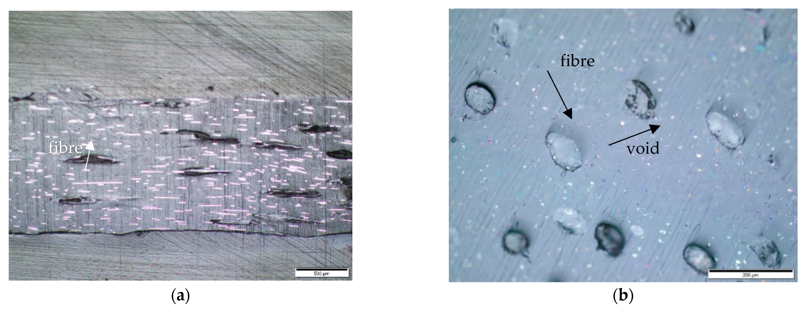
Hybridising the hemp with recycled carbon fibre improved the surface aesthetics of the rotationally moulded composites. This is because the hybrid composite has more but smaller voids on its surface compared to the hemp–PE composite, as shown in Figure 7a,b. This behaviour is attributed to the high thermal conductivity of the carbon fibre (5 to 15 W·m−1·K−1) [44], which assisted the sintering of the hemp–PE composite pellets during the process. It is known that the amount of formed conductive chains exponentially increases with the content of carbon fibre, thereby increasing the thermal conductivity of a composite [45]. This reduction in the void’s size has not reduced the porosity of the final composites (Table 2). However, this might have contributed to the improved tensile properties observed in the hybrid composites compared to the composites only reinforced with hemp fibre.
Pinholes are commonly present on the surface of rotationally moulded composites due to the release of air trapped during the process. Usually, the use of external pressure minimises gas inclusions in composites, even those that occur within the filling structure. However, the absence of pressure and shear forces during rotational moulding can lead to a significant number of voids [46,47].

3.4. Effect of Hybridisation on the Mechanical Properties of Rotationally Moulded Composites

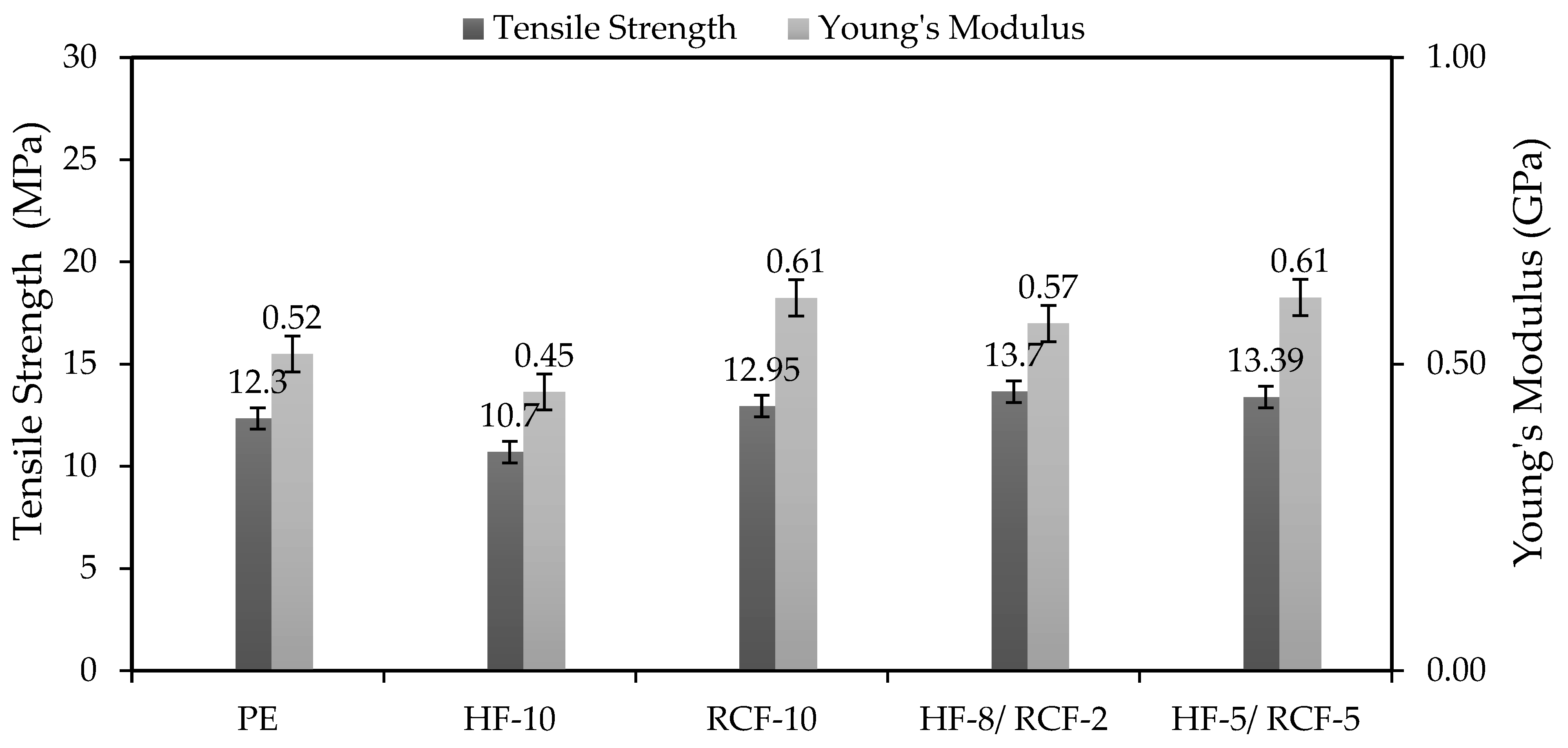
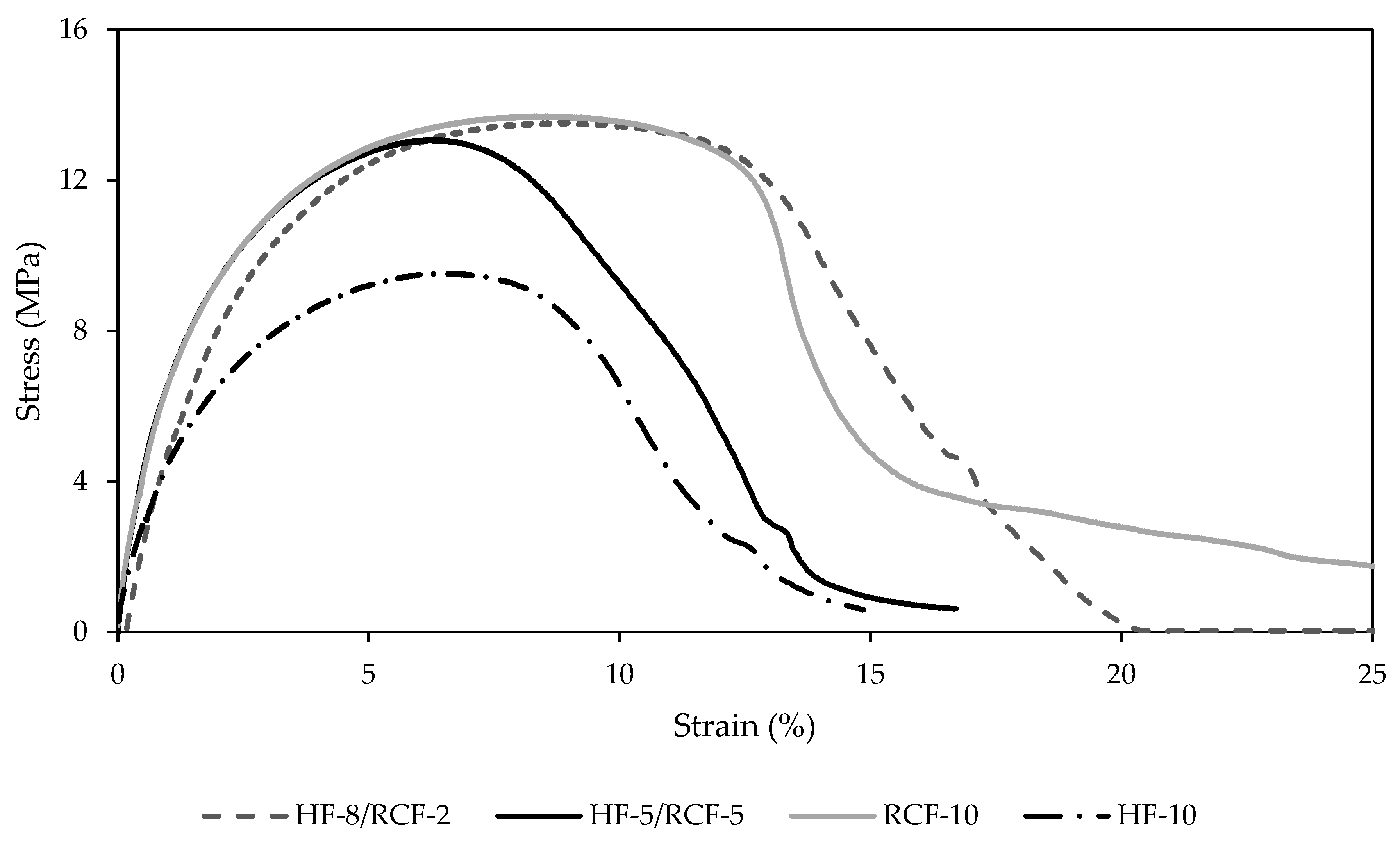
In general, hybridising hemp with recycled carbon fibre resulted in a stiffer and stronger composite (about 30%) than their natural fibre counterparts, as shown in Figure 8. Furthermore, Figure 9 presents exemplary stress–strain curves for these composites. It shows that the incorporation of RCF into the HF–PE composite resulted in a notable increase in tensile strength. The hybrid composites showed a higher Young’s modulus (about 20%) than pure polyethylene, but no difference in tensile strength. This result was confirmed as statistically significant by the 2-sample t-test with 95% confidence. Likewise, the Young’s modulus of the hybrid composites increased with the recycled carbon fibre content (from 20 to 50%), which is attributed to the high stiffness of the RCF and the reduction in the size of the voids in the final composites. Likewise, a previous study showed that hybridising flax fibre with carbon fibre resulted in greater stiffness for the hybrid material relative to its natural fibre counterparts [48]. It was also observed that hybrid composites (5 wt.% RCF) had the same tensile properties as recycled carbon fibre–PE composites (10 wt.% RCF). This result shows that hemp fibre also contributed to the reinforcement of the hybrid composites. In general, the presence of pores in rotationally moulded composites weakens the stress transferred between the fibre and the matrix resulting in low tensile properties.

3.5. Effect of Hybridisation on Thermal Behaviour of Composites

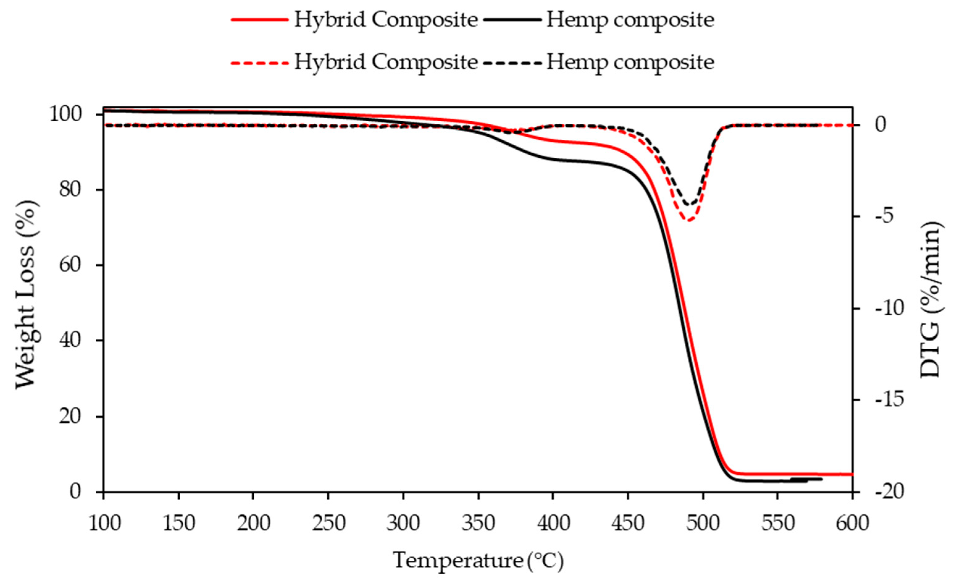
The TG and DTG curves of the hybrid and hemp–PE composites are shown in Figure 10. Both formulations show a two-stage degradation process between 250 and 500 °C. The first stage of weight loss from 200–360 °C is due to the thermal degradation of amorphous materials such as hemicellulose, lignin, and pectin, followed by cellulose. The final stage of weight loss ranging from 360–500 °C is due to the thermal degradation of cellulose and the remaining lignin. On the other hand, the carbon fibre is stable at high temperatures and inert environments, which is evidenced by the almost unchanged weight of the carbon fibre up to 500 °C.
Figure 10 shows that the onset of decomposition temperature for hemp and hemp–PE is recorded at 230 and 370 °C, respectively; however, the decomposition temperature for the carbon/hemp fibre hybridised composite samples was approximately 385 °C and the residual charcoal content increased from 2.9 to 4.7% with the hybridisation of the hemp composite. These results show a slight increase in the onset of decomposition temperature and the temperature of maximum degradation rate upon introducing recycled carbon fibre onto the hemp fibre-PE composites. The obtained properties are summarised in Table 3.

4. Conclusions

The treatment of the recycled carbon fibre with nitric acid for up to 120 min was beneficial for increasing the number of oxygen groups in the fibre. This resulted in an increased fibre roughness and better fibre–matrix adhesion along with MAPE. Therefore, the tensile-testing procedure revealed increased tensile strength and Young’s modulus in the filaments of the treated RCF–PE compared to the untreated RCF–PE composites. However, this result was not reproduced in the rotationally moulded composites, and no significant difference in the tensile properties’ results was observed between the composites with treated and untreated carbon fibres. In conclusion, the treatment of recycled carbon fibre with HNO3 before rotational moulding is not advantageous considering the slight improvement in fibre–matrix adhesion, the time consumed, and the hazardous waste generated.
On the other hand, the rotationally moulded composites reinforced with RCF had a superior Young’s modulus than PE regardless of the fibre treatment. As the RCF weight ratio increased up to 5 wt.%, the hybrid composite demonstrated the best Young’s modulus. In addition, the hybridisation of hemp fibre with recycled carbon fibre resulted in composites with superior tensile strength and Young’s modulus than neat polyethylene. This result was due to the high tensile properties of the recycled carbon fibre with reduced void sizes on the surface of the hybrid composite compared to the hemp–PE composite. Although there are many hurdles associated with the addition of fibres in polymers for rotational moulding, it was demonstrated that PE composites using RCF and hemp fibres with improved thermal and tensile properties can be produced by rotational moulding.

Author Contributions

Writing—original draft, M.O.; Writing—review & editing, M.O. and C.G.; Supervision, K.L.P. All authors have read and agreed to the published version of the manuscript.

Funding

This research received no external funding.

Institutional Review Board Statement

Not applicable.

Informed Consent Statement

Not applicable.

Data Availability Statement

Not applicable.

Conflicts of Interest

The authors declare no conflict of interest.

References

  1. Crawford, R.J. Practical Guide to Rotational Moulding; Smithers Rapra: Shawbury, UK, 2012. [Google Scholar]
  2. Crawford, R.J.; Throne, J.L. Rotational Molding Technology; William Andrew: Belfast, UK, 2001. [Google Scholar]
  3. Baxendale, M.; McGree, J.M.; Bellette, A.; Corry, P. Machine-based production scheduling for rotomoulded plastics manufacturing. Int. J. Prod. Res. 2021, 59, 1301–1318. [Google Scholar] [CrossRef]
  4. Liu, S.-J.; Peng, K.-M. Rotational molding of polycarbonate reinforced polyethylene composites: Processing parameters and properties. Polym. Eng. Sci. 2010, 50, 1457–1465. [Google Scholar] [CrossRef]
  5. Bhabha, H. A New Generation of High Stiffness Rotational Moulding Materials. Ph.D. Thesis, Manchester Metropolitan University, Manchester, UK, 2015. [Google Scholar]
  6. López-Bañuelos, R.H.; Moscoso, F.J.; Ortega-Gudiño, P.; Mendizabal, E.; Rodrigue, D.; González-Núñez, R. Rotational molding of polyethylene composites based on agave fibers. Polym. Eng. Sci. 2012, 52, 2489–2497. [Google Scholar] [CrossRef]
  7. Wang, B.; Panigrahi, S.; Tabil, L.; Crerar, W.J. Pre-treatment of flax fibers for use in rotationally molded biocomposites. J. Reinf. Plast. Compos. 2007, 26, 447–463. [Google Scholar] [CrossRef]
  8. Oliveira, M.A.; Pickering, K.L.; Sunny, T.; Lin, R.J. Treatment of hemp fibres for use in rotational moulding. J. Polym. Res. 2021, 28, 53. [Google Scholar] [CrossRef]
  9. Pickering, K.L.; Efendy, M.G.A.; Le, T.M. A review of recent developments in natural fibre composites and their mechanical performance. Compos. Part A Appl. Sci. Manuf. 2016, 83, 98–112. [Google Scholar] [CrossRef] [Green Version]
  10. Li, X.; Tabil, L.G.; Panigrahi, S. Chemical treatments of natural fiber for use in natural fiber-reinforced composites: A review. J. Polym. Environ. 2007, 15, 25–33. [Google Scholar] [CrossRef]
  11. Pickering, K. Properties and Performance of Natural-Fibre Composites; Elsevier: Cambridge, UK, 2008. [Google Scholar]
  12. Davoodi, M.; Sapuan, S.; Ahmad, D.; Ali, A.; Khalina, A.; Jonoobi, M. Mechanical properties of hybrid kenaf/glass reinforced epoxy composite for passenger car bumper beam. Mater. Des. 2010, 31, 4927–4932. [Google Scholar] [CrossRef]
  13. Thwe, M.M.; Liao, K. Durability of bamboo-glass fiber reinforced polymer matrix hybrid composites. Compos. Sci. Technol. 2003, 63, 375–387. [Google Scholar] [CrossRef]
  14. Mansor, M.R.; Sapuan, S.; Zainudin, E.S.; Nuraini, A.; Hambali, A. Hybrid natural and glass fibers reinforced polymer composites material selection using Analytical Hierarchy Process for automotive brake lever design. Mater. Des. 2013, 51, 484–492. [Google Scholar] [CrossRef]
  15. Samal, S.K.; Mohanty, S.; Nayak, S.K. Polypropylene—Bamboo/glass fiber hybrid composites: Fabrication and analysis of mechanical, morphological, thermal, and dynamic mechanical behavior. J. Reinf. Plast. Compos. 2009, 28, 2729–2747. [Google Scholar] [CrossRef]
  16. Samal, S.K.; Mohanty, S.; Nayak, S.K. Banana/glass fiber-reinforced polypropylene hybrid composites: Fabrication and performance evaluation. Polym. -Plast. Technol. Eng. 2009, 48, 397–414. [Google Scholar] [CrossRef]
  17. Aquino, E.; Sarmento, L.; Oliveira, W.; Silva, R. Moisture effect on degradation of jute/glass hybrid composites. J. Reinf. Plast. Compos. 2007, 26, 219–233. [Google Scholar] [CrossRef]
  18. Fiore, V.; Valenza, A.; Di Bella, G. Mechanical behavior of carbon/flax hybrid composites for structural applications. J. Compos. Mater. 2012, 46, 2089–2096. [Google Scholar] [CrossRef] [Green Version]
  19. Kore, S.; Spencer, R.; Ghossein, H.; Slaven, L.; Knight, D.; Unser, J.; Vaidya, U. Performance of hybridized bamboo-carbon fiber reinforced polypropylene composites processed using wet laid technique. Compos. Part C Open Access 2021, 6, 100185. [Google Scholar] [CrossRef]
  20. Ashworth, S.; Rongong, J.; Wilson, P.; Meredith, J. Mechanical and damping properties of resin transfer moulded jute-carbon hybrid composites. Compos. Part B Eng. 2016, 105, 60–66. [Google Scholar] [CrossRef] [Green Version]
  21. Flynn, J.; Amiri, A.; Ulven, C. Hybridized carbon and flax fiber composites for tailored performance. Mater. Des. 2016, 102, 21–29. [Google Scholar] [CrossRef]
  22. Keener, T.; Stuart, R.; Brown, T. Maleated coupling agents for natural fibre composites. Compos. Part A Appl. Sci. Manuf. 2004, 35, 357–362. [Google Scholar] [CrossRef]
  23. Prachayawarakorn, J.; Khunsumled, S.; Thongpin, C.; Kositchaiyong, A.; Sombatsompop, N. Effects of silane and MAPE coupling agents on the properties and interfacial adhesion of wood-filled PVC/LDPE blend. J. Appl. Polym. Sci. 2008, 108, 3523–3530. [Google Scholar] [CrossRef]
  24. Cisneros-López, E.O.; González-López, M.E.; Pérez-Fonseca, A.A.; González-Núñez, R.; Rodrigue, D.; Robledo-Ortíz, J.R.J. Effect of fiber content and surface treatment on the mechanical properties of natural fiber composites produced by rotomolding. Compos. Interfaces 2017, 24, 35–53. [Google Scholar] [CrossRef]
  25. Hanana, F.E.; Chimeni, D.Y.; Rodrigue, D.J. Morphology and mechanical properties of maple reinforced LLDPE produced by rotational moulding: Effect of fibre content and surface treatment. Polym. Compos. 2018, 26, 299–308. [Google Scholar] [CrossRef]
  26. Pimenta, S.; Pinho, S.T. Recycling carbon fibre reinforced polymers for structural applications: Technology review and market outlook. Waste Manag. 2011, 31, 378–392. [Google Scholar] [CrossRef] [PubMed] [Green Version]
  27. Tapper, R.J.; Longana, M.L.; Norton, A.; Potter, K.D.; Hamerton, I. An evaluation of life cycle assessment and its application to the closed-loop recycling of carbon fibre reinforced polymers. Compos. Part B Eng. 2020, 184, 107665. [Google Scholar] [CrossRef]
  28. Bledzki, A.K.; Seidlitz, H.; Krenz, J.; Goracy, K.; Urbaniak, M.; Rösch, J.J. Recycling of Carbon Fiber Reinforced Composite Polymers—Review—Part 2: Recovery and Application of Recycled Carbon Fibers. Polymers 2020, 12, 3003. [Google Scholar] [CrossRef] [PubMed]
  29. Tamburri, E.; Orlanducci, S.; Terranova, M.; Valentini, F.; Palleschi, G.; Curulli, A.; Brunetti, F.; Passeri, D.; Alippi, A.; Rossi, M. Modulation of electrical properties in single-walled carbon nanotube/conducting polymer composites. Carbon 2005, 43, 1213–1221. [Google Scholar] [CrossRef]
  30. Shin, S.; Jang, J.; Yoon, S.-H.; Mochida, I. A study on the effect of heat treatment on functional groups of pitch based activated carbon fiber using FTIR. Carbon 1997, 35, 1739–1743. [Google Scholar] [CrossRef]
  31. Moreno-Castilla, C.; López-Ramón, M.; Carrasco-Marın, F. Changes in surface chemistry of activated carbons by wet oxidation. Carbon 2000, 38, 1995–2001. [Google Scholar] [CrossRef]
  32. Zhang, Y.; Zhu, S.; Liu, Y.; Yang, B.; Wang, X. The mechanical and tribological properties of nitric acid-treated carbon fiber-reinforced polyoxymethylene composites. J. Appl. Polym. Sci. 2015, 132, 41812. [Google Scholar] [CrossRef]
  33. Tiwari, S.; Bijwe, J. Surface treatment of carbon fibers–A review. Procedia Technol. 2014, 14, 505–512. [Google Scholar] [CrossRef] [Green Version]
  34. Tiwari, S.; Bijwe, J.; Panier, S. Tribological studies on polyetherimide composites based on carbon fabric with optimized oxidation treatment. Wear 2011, 271, 2252–2260. [Google Scholar] [CrossRef]
  35. Meyer, L.O.; Schulte, K.; Grove-Nielsen, E. CFRP-recycling following a pyrolysis route: Process optimization and potentials. J. Compos. Mater. 2009, 43, 1121–1132. [Google Scholar] [CrossRef] [Green Version]
  36. Sharma, M.; Gao, S.; Mäder, E.; Sharma, H.; Wei, L.Y.; Bijwe, J. Carbon fiber surfaces and composite interphases. Compos. Sci. Technol. 2014, 102, 35–50. [Google Scholar] [CrossRef]
  37. Tian, H.; Yao, Y.; Liu, D.; Li, Y.; Jv, R.; Xiang, G.; Xiang, A. Enhanced Interfacial Adhesion and Properties of Polypropylene/Carbon Fiber Composites by Fiber Surface Oxidation in Presence of a Compatibilizer. Polym. Compos. 2019, 40, E654–E662. [Google Scholar] [CrossRef]
  38. Li, J.; Sun, F. The interfacial feature of thermoplastic polystyrene composite filled with nitric acid oxidized carbon fiber. Surf. Interface Anal. Int. J. Devoted Dev. Appl. Tech. Anal. Surf. Interfaces Thin Film. 2009, 41, 255–258. [Google Scholar] [CrossRef]
  39. Savas, L.A.; Tayfun, U.; Dogan, M. The use of polyethylene copolymers as compatibilizers in carbon fiber reinforced high density polyethylene composites. Compos. Part B Eng. 2016, 99, 188–195. [Google Scholar] [CrossRef]
  40. Zhou, Z.; Xu, M.; Yang, Z.; Li, X.; Shao, D. Effect of maleic anhydride grafted polyethylene on the properties of chopped carbon fiber/wood plastic composites. J. Reinf. Plast. Compos. 2014, 33, 1216–1225. [Google Scholar] [CrossRef]
  41. Karsli, N.G.; Aytac, A. Effects of maleated polypropylene on the morphology, thermal and mechanical properties of short carbon fiber reinforced polypropylene composites. Mater. Des. 2011, 32, 4069–4073. [Google Scholar] [CrossRef]
  42. Wong, K.; Mohammed, D.S.; Pickering, S.; Brooks, R. Effect of coupling agents on reinforcing potential of recycled carbon fibre for polypropylene composite. Compos. Sci. Technol. 2012, 72, 835–844. [Google Scholar] [CrossRef]
  43. Fu, S.-Y.; Lauke, B. Effects of fiber length and fiber orientation distributions on the tensile strength of short-fiber-reinforced polymers. Compos. Sci. Technol. 1996, 56, 1179–1190. [Google Scholar] [CrossRef]
  44. Karakashov, B.; Taghite, M.B.; Kouitat, R.; Fierro, V.; Celzard, A. Mechanical and thermal behavior of fibrous carbon materials. Materials 2021, 14, 1796. [Google Scholar] [CrossRef]
  45. Agari, Y.; Uno, T. Thermal conductivity of polymer filled with carbon materials: Effect of conductive particle chains on thermal conductivity. J. Appl. Polym. Sci. 1985, 30, 2225–2235. [Google Scholar] [CrossRef]
  46. Andrzejewski, J.; Krawczak, A.; Wesoły, K.; Szostak, M. Rotational molding of biocomposites with addition of buckwheat husk filler. Structure-property correlation assessment for materials based on polyethylene (PE) and poly (lactic acid) PLA. Compos. Part B Eng. 2020, 202, 108410. [Google Scholar] [CrossRef]
  47. Arribasplata-Seguin, A.; Quispe-Dominguez, R.; Tupia-Anticona, W.; Acosta-Sullcahuamán, J. Rotational molding parameters of wood-plastic composite materials made of recycled high density polyethylene and wood particles. Compos. Part B Eng. 2021, 217, 108876. [Google Scholar] [CrossRef]
  48. Dhakal, H.; Zhang, Z.; Guthrie, R.; MacMullen, J.; Bennett, N. Development of flax/carbon fibre hybrid composites for enhanced properties. Carbohydr. Polym. 2013, 96, 1–8. [Google Scholar] [CrossRef] [PubMed]
Figure 1. FT-IR analysis of untreated (URCF) and treated recycled carbon fibre (RCF) for 60, 120, and 180 min.
Jcs 06 00352 g001
Figure 2. SEM images of recycled carbon fibre (RCF). (a) Untreated RCF; (b) RCF treated for 60 min; (c) RCF treated for 120 min; (d) RCF treated for 180 min.
Jcs 06 00352 g002aJcs 06 00352 g002b
Figure 3. Tensile testing of filaments of composites with treated (T)/untreated and (U) recycled carbon fibre (RCF) with/without MAPE compared to pure PE. The error bars indicate one standard deviation.
Jcs 06 00352 g003
Figure 4. Optical microscope images of extruded filaments of RCF and PE. (a) Horizontal cross-sectional view—500 µm; (b) vertical cross-sectional view—200 µm.
Jcs 06 00352 g004
Figure 5. SEM images of fractured surface of extruded filaments of RCF/MAPE/PE composites. (a) and (b) Treated RCF; (c) and (d) Untreated RCF.
Jcs 06 00352 g005
Figure 6. Tensile testing of rotationally moulded composites. PE—polyethylene, U—untreated, T—treated, RCF—recycled carbon fibre, and MAPE—maleic anhydride polyethylene. The error bars indicate one standard deviation.
Jcs 06 00352 g006
Figure 7. Figure 7. Optical microscopy image of the surface of rotationally moulded composites reinforced with hemp (a) and hybrid (b). 500 µm scale.
Jcs 06 00352 g007
Figure 8. Tensile testing of rotationally moulded composites. PE—polyethylene, HF—hemp fibre, and RCF—recycled carbon fibre followed by fibre content (wt.%). The error bars indicate one standard deviation.
Jcs 06 00352 g008
Figure 9. Example of a Stress vs Strain curve of rotationally moulded composites. HF—hemp fibre and RCF—recycled carbon fibre followed by fibre content (wt.%).
Jcs 06 00352 g009
Figure 10. Thermal analysis of hybrid and hemp-reinforced rotationally moulded PE composites.
Jcs 06 00352 g010
Table 1. Result of FT-IR analysis.
Wavelength (cm−1)Functional GroupBand Assignment
3384OHWater absorption
2900C=H, CH2Stretching of the methyl and methylene groups, hydrocarbon chains
1630C=C and C=OStretching vibration in conjugated carbonyl (C=O) with C=C in the graphene wall
1385COOHCarboxyl (COOH) group
1052OHO-H stretching vibration
Table 2. Porosity of rotationally moulded composites. PE—polyethylene, U—untreated, T—treated, RCF—recycled carbon fibre, and MAPE— maleic anhydride polyethylene.
SamplePorosity (% Area)
50(THU1.5)/50(UCU1.5)6.8
THU1.57.7
Table 3. Results of TGA analysis.
SampleOnset Decomposition Temperature (°C)The Temperature at the Main Decomposition Peak (°C)Residual Char Yield (%)
Hybrid composites
HF-5/RCF-5
3855004.7
Hemp Composites
HF-10
3704902.9
Publisher’s Note: MDPI stays neutral with regard to jurisdictional claims in published maps and institutional affiliations.