Article

Influence of Matrix Strength on Bridging Performance of Fiber-Reinforced Cementitious Composite with Bundled Aramid Fiber

1
Division of Engineering Mechanics and Energy, University of Tsukuba, Tsukuba 305-8577, Japan
2
Degree Program in Engineering Mechanics and Energy, Graduate School of Science and Technology, University of Tsukuba, Tsukuba 305-8577, Japan
*
Author to whom correspondence should be addressed.
J. Compos. Sci. 2022, 6(5), 131; https://doi.org/10.3390/jcs6050131
Submission received: 29 March 2022 / Revised: 22 April 2022 / Accepted: 26 April 2022 / Published: 28 April 2022
(This article belongs to the Special Issue High Performance Fiber-Reinforced Cementitious Composites)

Abstract

:
The bundled aramid fiber has good bond properties in the cementitious matrix, and is expected to have high bridging performance in the fiber-reinforced cementitious composite (FRCC). To investigate the influence of matrix strength on the bridging performance of FRCC with the bundled aramid fiber, the uniaxial tension test of FRCC, the pullout test for an individual fiber, and the calculation of bridging law are conducted with the main parameters of matrix strength and fiber volume fraction. From the test results, the maximum tensile load of FRCC and the maximum pullout load of an individual fiber increase as the matrix strength also increases. The calculation result of the bridging law considering the effect of matrix strength expresses the bridging performance of the bundled aramid fiber well. The calculation result also shows that the bridging strength has a linear relationship up to a compressive strength of around 50 MPa.

1. Introduction

The fiber-reinforced cementitious composite (FRCC) is one of the cementitious materials in which short discrete fibers with certain volume fractions are mixed into cementitious matrix to improve the brittle behavior of composites, especially in the tensile and bending field. Compared with traditional cementitious materials such as concrete and mortar, the FRCC is expected to exhibit a high performance in ductility because of the fiber bridging that transfers the tensile force through cracks [1]. In addition, the FRCC is also expected to have high durability when it is used in reinforced concrete (RC) structures, because fibers can control the crack openings in the matrix, which prohibits the penetrations of aggressive attacks to deteriorate the internal reinforcing rebars and the FRCC itself [2,3,4].
According to various studies, steel fibers or polymeric fibers such as polyethylene (PE), polyvinyl alcohol (PVA), and polypropylene (PP) fibers have been utilized in the FRCC [5]. While FRCC mixing with steel fibers commonly shows tension softening behavior after initial cracking, polymeric fibers are commonly used rather than steel fibers in the FRCC, which shows higher ductility. Aramid fibers are known as one of the polymeric fibers that have high tensile strength, durability, and heat and chemical resistance [6]. It has been reported that aramid fibers have been used for the strengthening of RC structures by the external bonding of a fiber sheet [7,8]. However, few research studies can be found concerning FRCC mixed with discrete aramid fibers [9,10]. Since a commercially provided single aramid fiber has a small diameter of 12 μm, it cannot be expected that the aramid fibers and the cementitious matrix have strong bond strengths [11]. In the case of the PVA fiber, it has been considered that the alcohol group in a PVA molecule leads to a good bond performance with the cementitious matrix [12,13]. However, as with other types of polymeric fibers, the smooth surface of an individual fiber cannot generate a strong bond resistance. In the case of PP fibers, for example, a deformed shape on an individual fiber surface is formed to improve bond resistance [14]. For these reasons, this study has focused on the bundled aramid fiber, which is made by bundling original yarns of the aramid fiber. The bundled aramid fiber shows a rough surface, and it is expected to have good bond performance with the cementitious matrix by mechanical resistance.
The high tensile performance of FRCC is caused by the bridging effect of fibers across cracks after the first cracking of the matrix. Since the bridging effect of fibers is strongly influenced by the fiber types and dimensions, the pullout behavior of an individual fiber from a cementitious matrix has been investigated, to reflect these factors on the bridging effect. A number of researchers have conducted pullout tests for various types and dimensions of fibers, e.g., steel fiber [15], PVA fiber [12], nylon, and PP fibers [16]. The authors also conducted the pullout test of an individual fiber for the bundled aramid fiber [17]. The test results concluded that the bond strength shows proportional relations with the embedded length of the fiber, and a bilinear model for the pullout load–slip curve has been proposed. Some test results also revealed fiber rupturing, which means that the bond performance of the bundled aramid fiber is good enough for the effective use of a high-strength aramid fiber. However, the effect of matrix strength on the bond performance of the bundled aramid fiber is still unclear. It is expected that the high-strength matrix brings higher bond strength because of the mechanical resistance between the rough surface of the fiber and the matrix.
The tensile performance of the FRCC after the first cracking of the matrix is characterized by a tensile stress-crack width relationship called bridging law. The bridging law can be obtained by the integral calculus of forces carried by individual fibers pulled out from the matrix [18]. The authors also performed a calculation of the bridging law of the PVA fiber [19], considering the snubbing effect [20] and the fiber strength degradation [12]. The calculation of the bridging law for a bundled aramid fiber was also carried out by the authors [17], and the calculation results show good adaptabilities with the uniaxial tensile test results. In these studies, however, the mixture proportion of cementitious matrix was limited. There is unknown information about the effect of matrix strength on the tensile properties of the FRCC. The matrix strength, which is generally exhibited by compressive strength in the case of conventional concrete, is one of the most important factors of the cementitious composites considering the use of FRCC for the structural elements, such as coupling beams [21], columns [22], seismic walls [23], beam–column joints [24], and so on. As far as the authors know, however, there is no previous study in which the mixture proportion was selected as the experimental parameter because of the difficulties of the control of fresh properties of the cementitious matrix.
The main objective of this study is to investigate the influence of matrix strength on the bridging performance of FRCC with the bundled aramid fiber. In this study, matrix strength and fiber volume fraction are considered as main parameters. A uniaxial tension test is conducted for rectangular prism specimens with slits to find out the relationship between bridging performance and the two parameters. For the purpose of characterizing the pullout behavior of the individual fiber from the matrix, a pullout test is also conducted for the same matrix proportions with the ones in the uniaxial tension test. Finally, by using the pullout characteristics obtained from the pullout test, a calculation of the bridging law is carried out, and the calculation results are compared with the uniaxial tension test results.

2. Used Materials

The bundled aramid fiber shown in Figure 1 is targeted in this study. The original yarns of aramid fibers with a nominal diameter of 12 µm are twisted to form a thick individual fiber and sized so as not to unravel in the FRCC. The diameter of the bundled fiber is 0.5 mm, and the length of the chopped fiber for FRCC is 30 mm. Table 1 shows the dimensions and mechanical characteristics of the fiber. The weight of bundled aramid fibers mixed into FRCC for the volume fractions of 1% and 2% is 13.9 kg/m3 and 27.8 kg/m3, respectively.
Table 2 shows the three mixture proportions of the cementitious matrix applied in this study. The water/cement ratio in the three mixture proportions is varied to obtain different target compressive strengths, while the water/binder ratio is kept constant with similar fresh properties by changing the unit weight of the fly ash. A coarse aggregate is not used to investigate the fundamental characteristics of FRCC. The naming of the series (Fc24, Fc36, and Fc48) is based on the target compressive strength of the mixtures as the specified strength for the design of the structural elements. These FRCCs show self-consolidating properties, even if the volume fraction of the fiber is over 2%.

3. Uniaxial Tension Test of FRCC

3.1. Specimens

A uniaxial tension test is conducted for FRCC rectangular prism specimens with slits. Since the unified standard or specification of the uniaxial tension test method for FRCC does not exist within the knowledge of the authors, the prism specimen shown in Figure 2 is prepared considering the ease of specimen setup and measuring the axial deformation at the crack position. The specimen is a rectangular prism with two bolts (M20) embedded at both ends to transfer the tensile load. In order to control the position of the crack opening, two slits were set on both narrow sides in the middle of the specimen. The depth and width of the slit are 20 mm and 3 mm, respectively. The area of the ligament is 60 × 70 mm2. The slits were made by a concrete cutter after the hardening of FRCC to avoid the influence of the flow of the matrix at the casting. The notched rectangular prism specimens with slits have been generally utilized to investigate the tensile characteristics of cementitious materials, such as the FRCC, in the same way as concrete [26,27].
The experimental parameters are matrix strength (mixture proportion shown in Table 2, i.e., Fc24, Fc36, and Fc48) and fiber volume fraction (0%, 1%, and 2%). Therefore, nine series of specimens were determined for the uniaxial tension test. Five specimens were manufactured for each series, so a total of 45 specimens were tested. Since the fresh FRCCs have self-consolidating properties, fresh FRCCs were poured from one end of the mold and allowed to flow naturally until the mold was fully filled. The specimens were cured in the natural environment until the days of loadings.
At the same time carrying out the uniaxial tension test, a compression test was also conducted to confirm the compressive strength and elastic modulus of the FRCC. For each series, three cylinder specimens (ϕ100 × 200 mm) were tested in accordance with JIS A 1108 [28] and JIS A 1149 [29]. The cylinder specimens were also cured in the natural environment until the days of the loadings. Table 3 lists the compressive properties of each series. As shown by the results, the exact compressive strengths were much higher than the target compressive strengths due to the use of high early strength Portland cement and long curing times. The compressive strength of the three mixture proportions showed obvious differences between each other.

3.2. Loading and Measurement

A uniaxial tension test is carried out using a universal testing machine with a capacity of 2MN. Figure 3 shows the setup of the loading and measurement for the uniaxial tension test. Since the increasing external moment caused by setup irregularity and local fracture caused by the secondary moment would be an inevitable factor in the experiment, pin-fix ends were applied at the boundaries to minimize possible effects on the results [30]. Two displacement transducers (Pi-type) were set at the middle area of 100 mm in length on both sides to measure the axial deformation at the slit position. The loading speed was set to be from 0.5 to 1 mm per minute as the head speed. Visible cracks observation and photographing were done after loading. In addition, the upper and lower parts of the specimen were forcibly pulled apart and fibers on the fracture surface were counted.

3.3. Failure Patterns

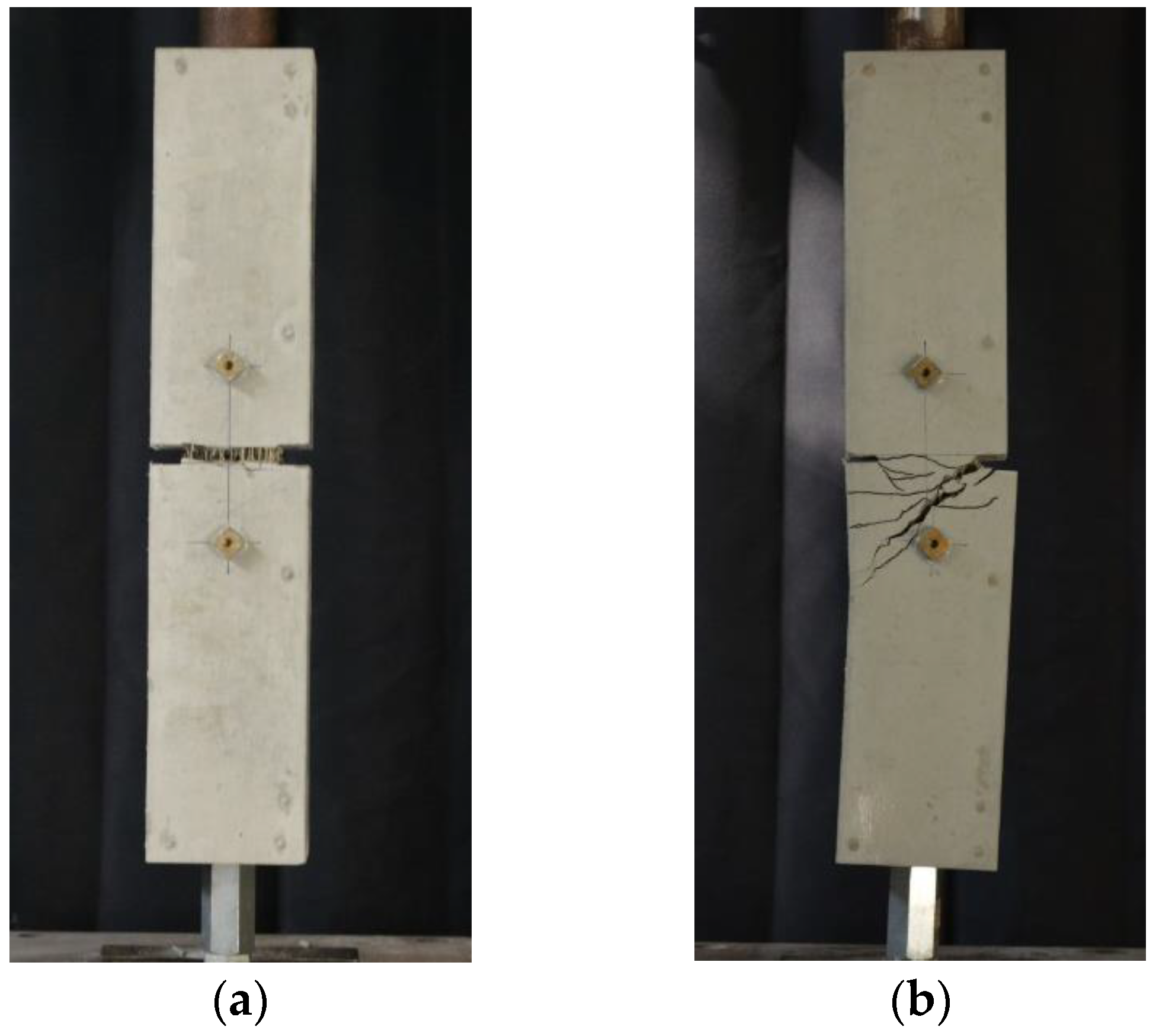
Figure 4 shows the typical failure modes of specimens. Failure modes of specimens can be mainly divided into two types: tensile failure and bending failure. The specimens of tensile failure generated obvious crack(s) throughout the slits on both sides. The specimens of bending failure generated slant cracks from one slit, and it did not penetrate the slit at the other side. The occurrence of bending failure is considered to be caused by the nonuniform distribution of the fibers in the matrix. The specimens, in which failure mode was detected to be bending failure, are not discussed in the following sections.
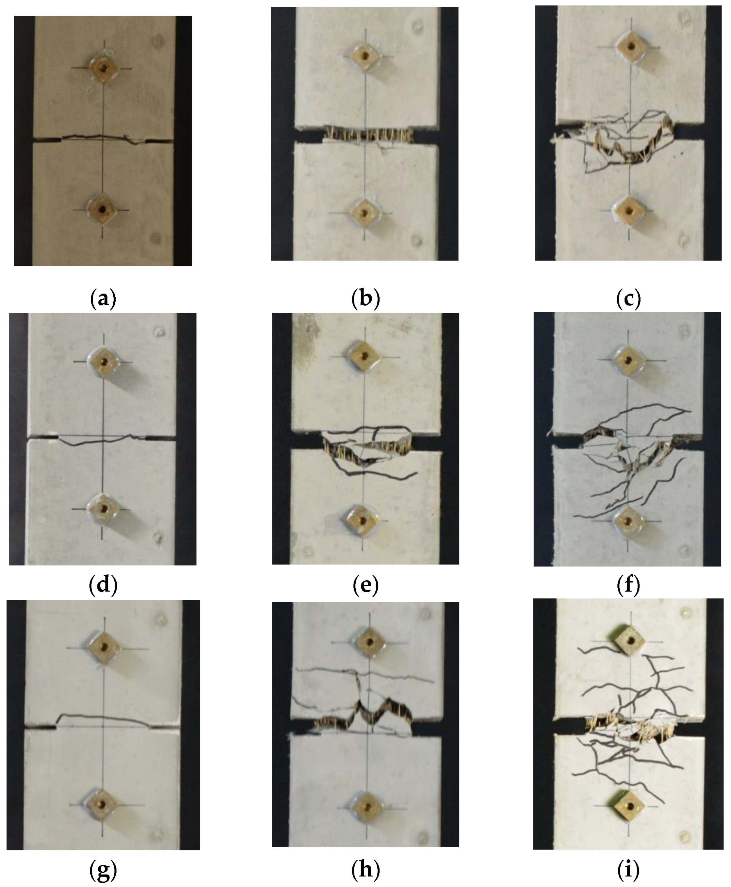
Figure 5 shows the examples of crack patterns of specimens in tensile failure. As revealed by the figure, specimens without fibers (Fc24-N, Fc36-N, and Fc48-N) only generated one crack throughout the slits. As for FRCC specimens, an obvious crack throughout slits could be observed while multiple fine cracks were generated near the slits. As for FRCC specimens, the number of cracks increases with increasing fiber volume fraction and matrix strength.
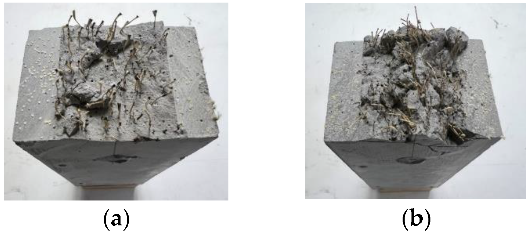
Figure 6 shows examples of the visual appearance of fracture surfaces in Fc36 series specimens. It could be detected that several fibers on the fracture surface unraveled when they were pulled out from the matrix. The number of fibers on the fracture surface of each specimen was counted after loading. The counted number is considered in comparing the tension test results and calculation of bridging laws in Section 5. The average numbers of fibers on the fracture surface were not proportional to the expected ones given by the planned fiber volume fractions. Although the measured number of fibers was added to the mixture, inconstant fiber distribution may be observed in the case of relatively small dimensions of the specimen.

3.4. Tensile Load vs. Axial Deformation Relatioonship

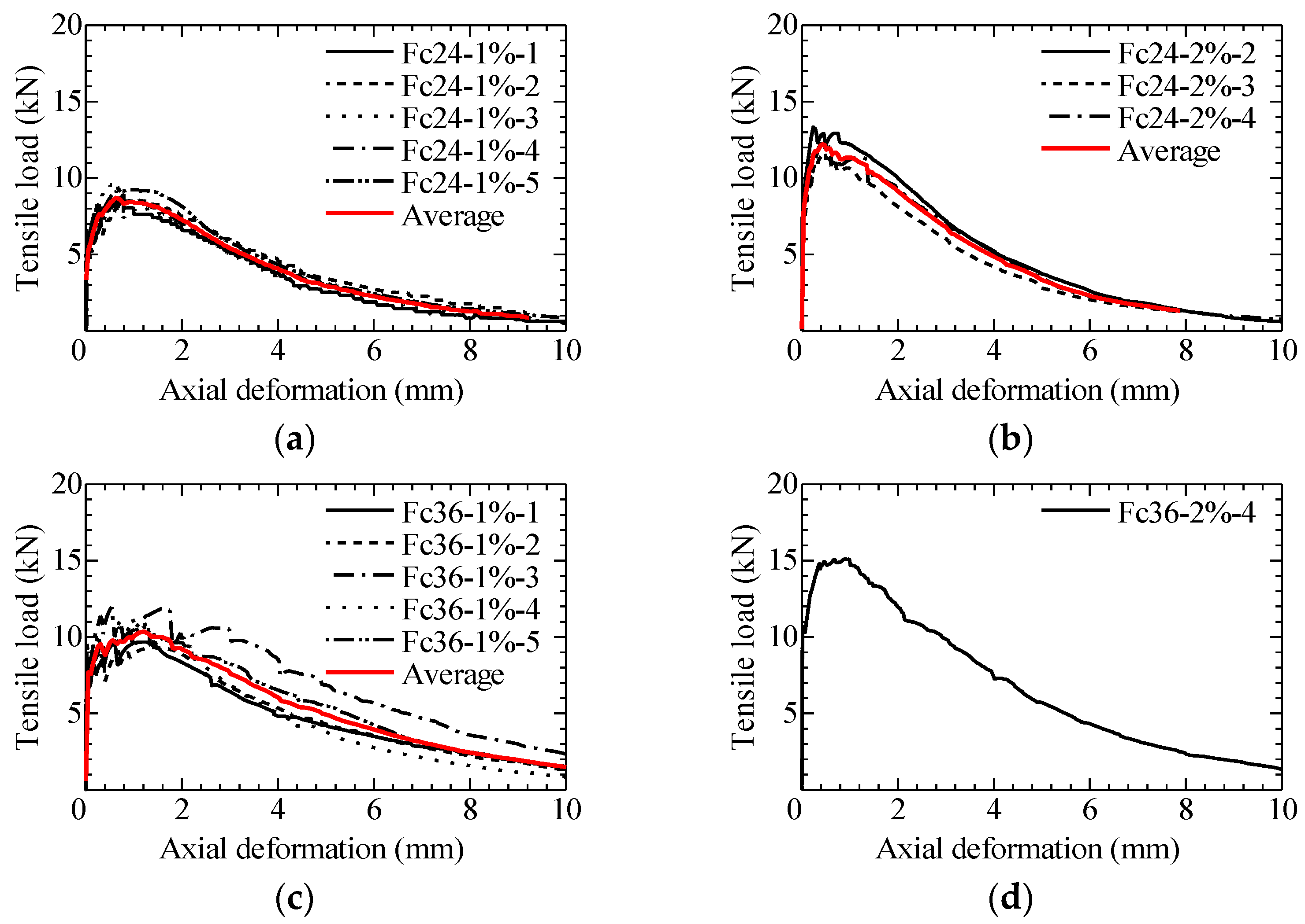
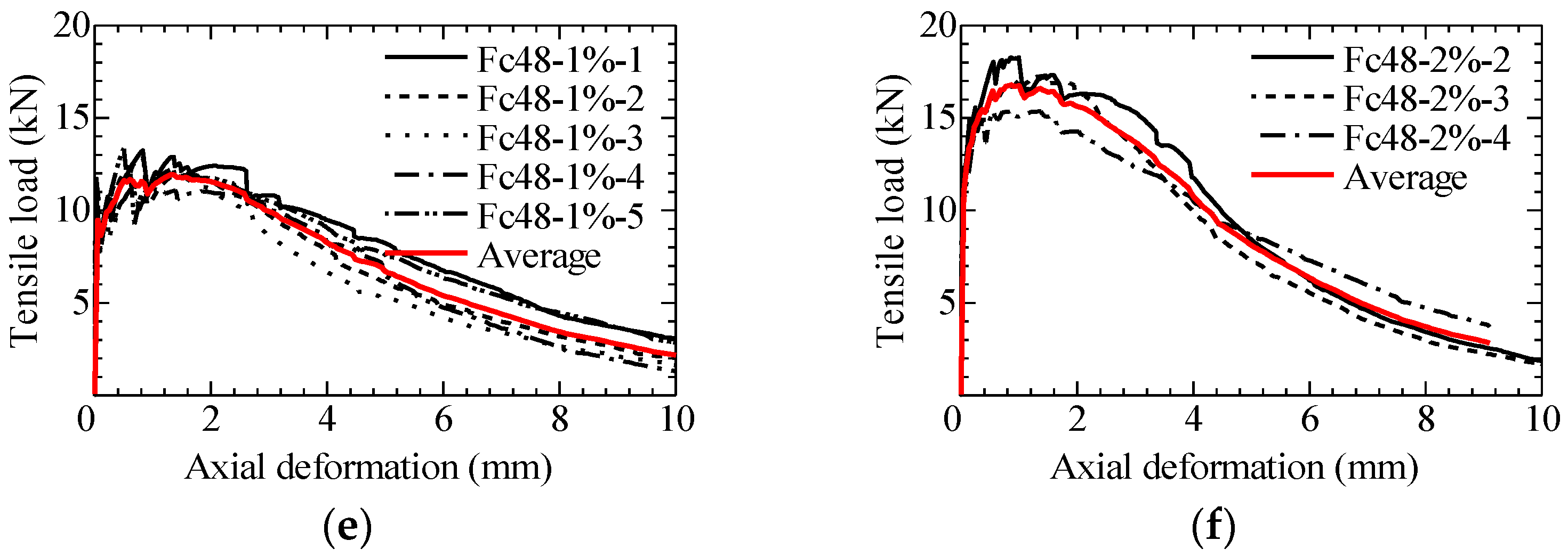
Figure 7 shows the tensile load-axial deformation relationship obtained from the uniaxial tension test. Only FRCC specimens showing tensile failure are plotted. In order to compare the tensile behavior between each series, the average curve of test results in each series is also shown in the figure as a red line. While specimens without fibers did not retain the tensile load after first cracking, the tensile load of FRCC specimens decreased gradually after the peak of a large axial deformation with a wide crack opening. In addition, FRCC specimens showed a tensile strain-hardening property that load-increases after the first crack is generated.
Table 4 summarizes the results of the uniaxial tension test. As revealed by the results, the tensile loads at the first crack of FRCC specimens are larger than those of specimens without fibers (Fc24-N, Fc36-N, and Fc48-N), indicating that the addition of fibers has an inhibitory effect on cracks occurring. The tensile loads at the first crack also increase with the increase of the matrix strength and fiber volume fraction. The maximum loads of FRCC specimens are larger than the tensile loads at first crack, which confirms a tensile strain-hardening property.
Figure 8 shows the relationship between maximum load and the experimental parameters, i.e., the compressive strength of FRCC and fiber volume fraction. The lines in the figure are connected by the average values of the maximum loads in each series. By comparing the specimens with the same fiber volume fraction, average maximum loads increase with the increase of compressive strength. On the other hand, by comparing the specimens with the same mixture proportion, average maximum loads increase as the fiber volume fraction increases.

4. Pullout Test of Individual Fiber

4.1. Specimens

Figure 9 shows the dimensions of the specimen for the pullout test of the individual bundled aramid fiber and the constitution of the mold. The specimen is a thin plate made of the matrix without a fiber in which an individual fiber is embedded at the center of the plate. The dimension in the plane section is 30 × 30 mm2, and the thickness of the plate is one of the experimental parameters. The mold consists of two acrylic plates and three rubber plates. A total of five plates are fixed by bolts so as not to cause any visible deformation of the rubber plates. An individual fiber is positioned by the holes of the upper and lower rubber plates. A cementitious matrix is poured from the injection hole and the ventilator holes function so as not to make air voids. The thickness of the specimen is varied by changing the thickness of the middle rubber plate. The dimensions of the specimen and the mold are exactly the same as those used in the authors’ previous study [17].
The experimental parameters are matrix strength (mixture proportion shown in Table 2, i.e., Fc24, Fc36, and Fc48) and the embedded length of fiber (thickness of the plate, 4 mm, 8 mm, and 12 mm). Therefore, nine series of specimens were determined for the pullout test. Five specimens were manufactured for each series, so a total of 45 specimens were basically tested. The matrix compressive strengths obtained by three cylinder specimens (ϕ100 × 200 mm) for each mixture proportion in the testing age (average 10-day curing time) were 26.5 MPa, 37.1 MPa, and 52.6 MPa for Fc24, Fc36, and Fc48 series specimens, respectively.

4.2. Loading and Measurement

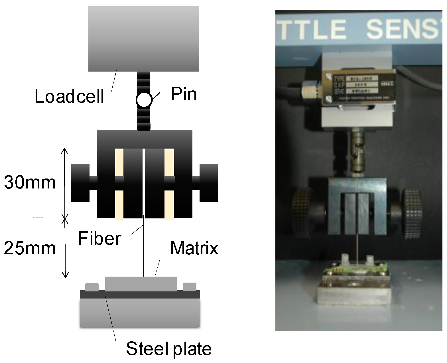
Pullout load was applied using an electronic system universal testing machine with a capacity of 200 N, as shown in Figure 10. The specimen was fixed via an adhered steel plate, and the embedded fiber was clamped directly by throwing a jig. The head speed was set to 1 mm per minute. The pullout load and head displacement were recorded. The loading and measurement methods are exactly the same as those applied in the authors’ previous study [17].

4.3. Failure Pattern and Pullout Load vs. Slip Relationship

In all of the tested specimens, the fiber was pulled out from the matrix without observing a clear rupture of the fiber, as shown in Figure 11. The surface of the fiber embedded in the matrix was a little damaged. Only one specimen (Fc24-8 mm) could not be loaded due to the damage to the specimen at the detaching of the mold.
Pullout load–slip curves of all the tested specimens are shown in Figure 12. The slip is calculated from the measured displacement of the loading head, subtracting the elongation of fiber outside the matrix, as in the previous study [17]. The averaged curves are calculated in each series of specimens to compare the curves between the different series of specimens. As shown in the figure, the curves generally show two stages, i.e., the load increases lineally up to the maximum load, and decreases gradually. The pullout load becomes almost zero when the slip reaches the embedded length of the fiber. The maximum load generally increases as the matrix strength and the embedded length also increase.

4.4. Evaluation of Maximum Pullout Load

Figure 13 shows the relationship between the maximum pullout load (Pmax) and compressive strength of the matrix (fc). The black plots show the average values of the maximum pullout loads in each series. It can be recognized that the maximum pullout loads increase as the matrix strength increases. Straight lines can be obtained by the least square method for each embedded length series of the specimens. The coefficients of the lines are different in each series. The maximum pullout load of longer embedded length specimens is highly influenced by the matrix strength. It is considered that the bond resistance of bundled fiber is due to a constant bond, along with the embedded fiber-like friction mechanism.
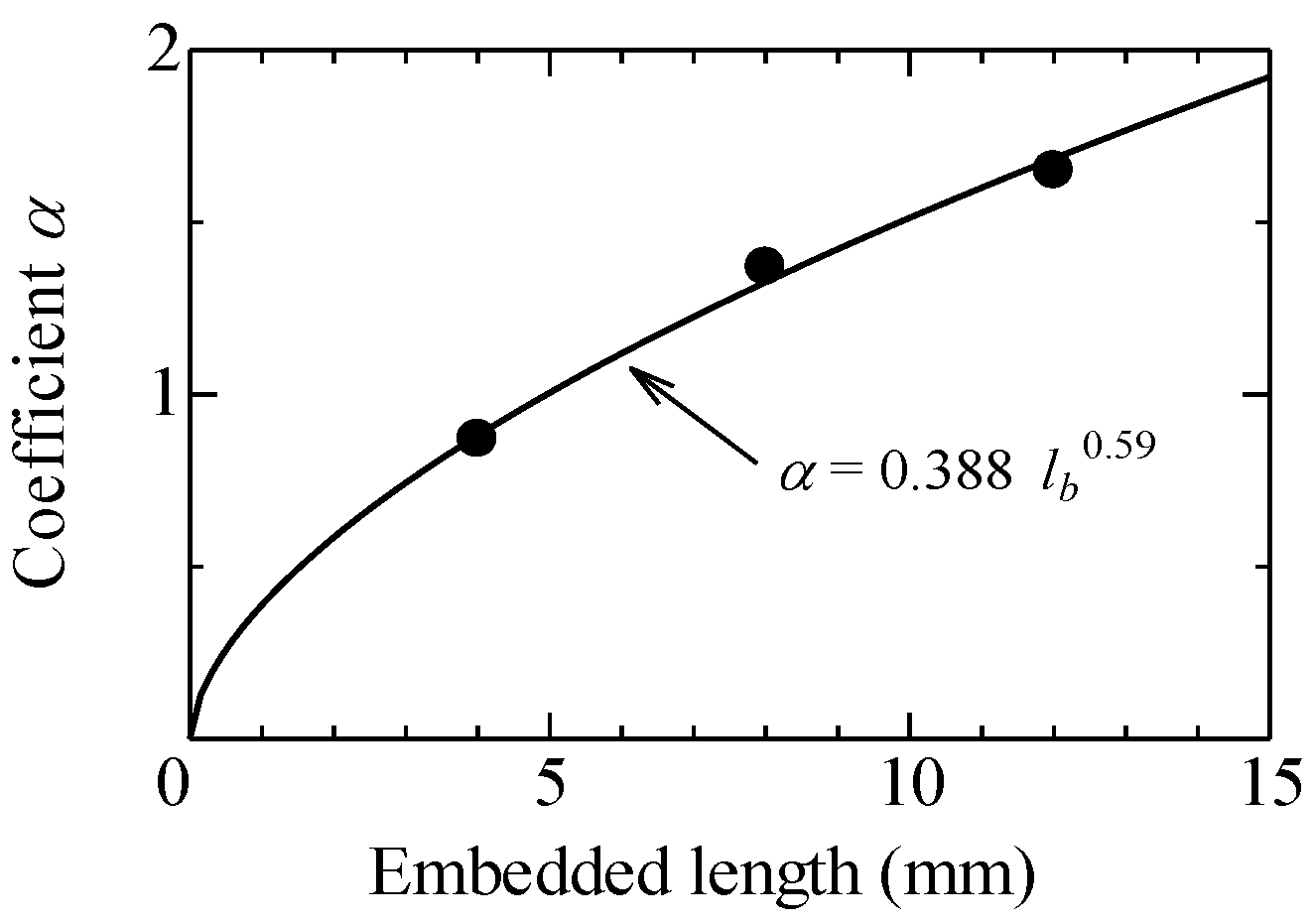
Figure 14 shows the relationship between the embedded length of the fiber (lb) and the coefficients of the lines (α) shown in Figure 13. The curve shown in the figure is obtained by the regression analysis as it is expressed by the powered function of the embedded length. Finally, the maximum pullout load can be evaluated by the following Equation (1).
Pmax = (0.388 lb 0.59) fc
where,
Pmax: maximum pullout load (N);
lb: embedded length of fiber (mm);
fc: compressive strength of matrix (MPa).

5. Calculation of Bridging Law and Comparison with Test Results

5.1. Calculation Method of Bridging Law

The calculation method of the bridging law is exactly the same as that in the authors’ previous study [17], except for the maximum pullout load of the individual fiber. In the authors’ previous study, the maximum pullout load was simply given by a proportional relationship with the embedded length without considering the matrix strength. The bridging law is obtained by the summation of forces carried by the individual bridging fibers considering the probability density function for fiber inclination angle, fiber centroidal location, snubbing effect due to fiber inclination angle, and the apparent rupture strength of the fiber. Though the bilinear model that is the same as that in the previous study for the pullout load–slip model is adapted, the maximum pullout load is given by Equation (1). The parameters for the calculation are summarized in Table 5.

5.2. Comparison of Calculation Result with Uniaxial Tension Test Result

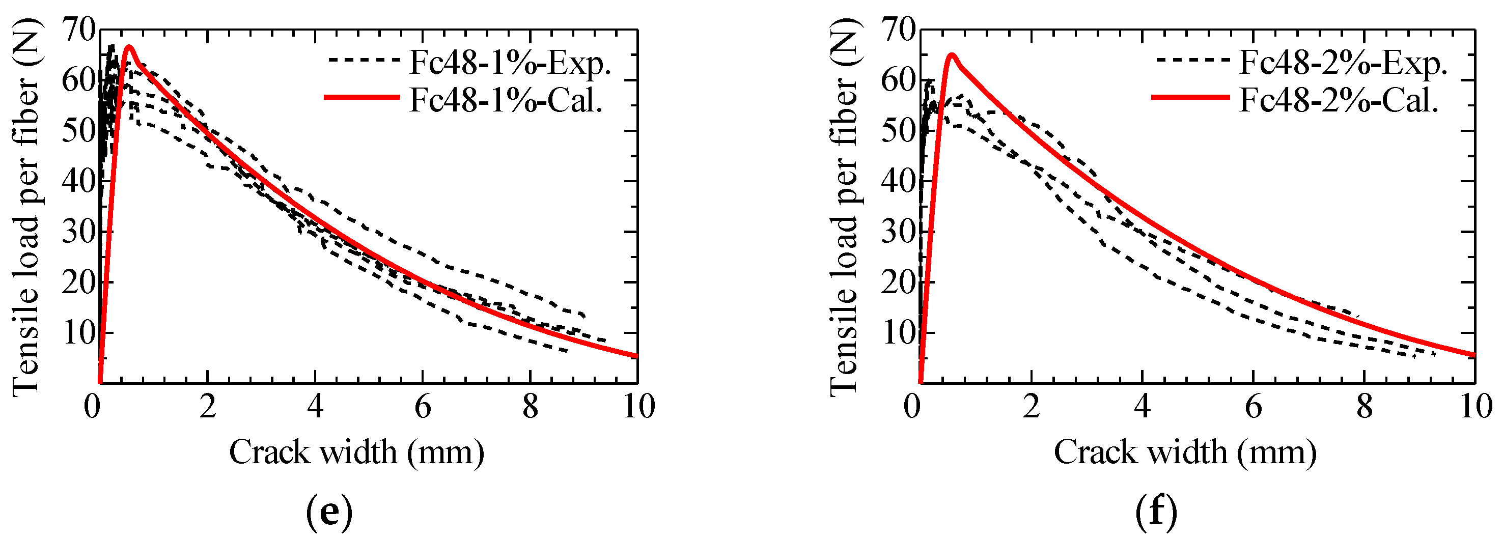
Figure 15 shows the comparison of tensile load-crack width curves between uniaxial tension test results and bridging law calculation results for each series of tested parameters. Table 6, Table 7 and Table 8 show the maximum tensile load obtained by the uniaxial tension test and bridging law calculation for Fc24, Fc36, and Fc48 series of specimens, respectively.
Tensile load is divided by the number of fibers, i.e., the counted number of fibers on the fracture surface in the case of the test results as described in Section 3.3, or the number of effective fibers [19] given by following Equation (2) in the case of the calculation. The crack width for the test results is obtained from the measured axial deformation divided by the number of cracks observed in the uniaxial tension test.
Nf = Vf Am / Af ηf
where,
Nf: number of effective fibers;
Vf: fiber volume fraction;
Am: cross-sectional area of matrix;
Af: cross-sectional area of individual fiber;
ηf: fiber effectiveness.
As seen in Figure 15, the calculation results of bridging law generally express the results of the uniaxial tension test well. Concerning the maximum load, the tensile maximum load per fiber of the averaged test results for Fc24, Fc36, and Fc48 series of specimens are 1.07, 0.97, and 0.93 times the maximum load obtained by the calculation, respectively. Thus, it is considered that the calculated bridging law considering the effect of matrix strength is adaptable to express the bridging performance of the bundled aramid fiber.
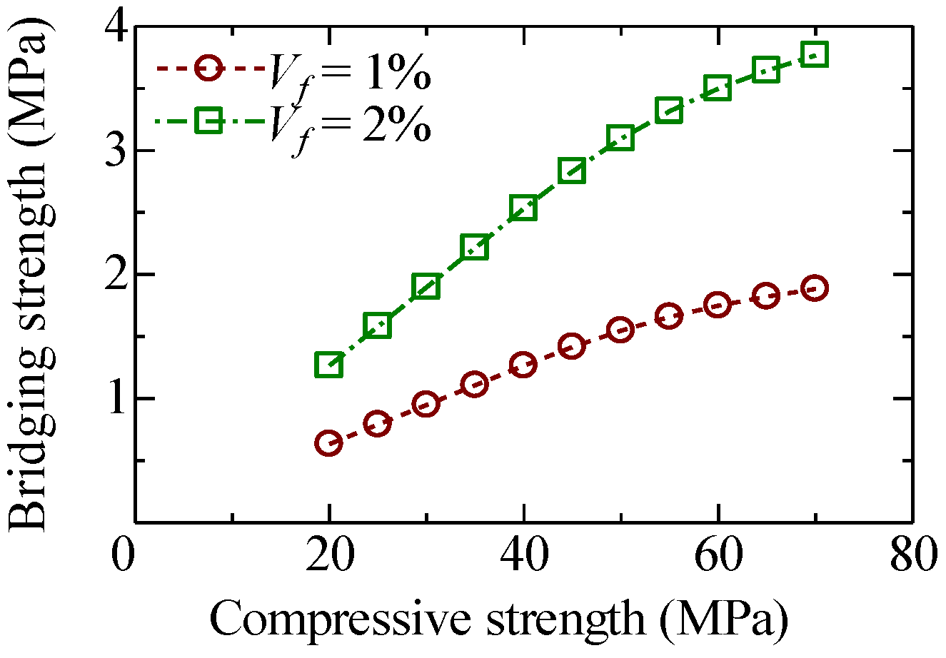
The effect of matrix strength on the maximum tensile load is investigated based on the bridging law calculation. Figure 16 shows the relationship between compressive strength and bridging strength, which is defined as the maximum tensile load divided by the cross-sectional area of the matrix. The calculations are carried out for several compressive strengths from 20 MPa to 70 MPa with fiber volume fractions (Vf) of 1% and 2%. The calculation results show that the bridging strength shows a linear relationship up to a compressive strength of around 50 MPa. Beyond 50 MPa, the increment of bridging strength becomes small. This is due to the rupture of fiber in the calculation.

6. Conclusions

To investigate the influence of matrix strength on the bridging performance of the FRCC with bundled aramid fiber, the uniaxial tension test of FRCC, the pullout test for an individual fiber, and the calculation of bridging law were conducted with the main parameters of matrix strength and fiber volume fraction. The following are concluded from this study.
1. From the uniaxial tension test results, maximum tensile load increases as the compressive strength of FRCC and fiber volume fraction increases.
2. From the pullout test results, the maximum pullout load generally increases as the matrix strength and the embedded length of the fiber also increase.
3. From the pullout test results, the maximum pullout load is evaluated by matrix compressive strength and the embedded length of fiber.
4. The calculated bridging law considering the effect of matrix strength is adaptable to express the bridging performance of the bundled aramid fiber.
5. The bridging law calculation result shows that the bridging strength shows a linear relationship up to a compressive strength of around 50 MPa. Beyond 50 MPa, the increment of bridging strength becomes small due to the rupture of the fiber.
It is considered that these findings will be valuable to evaluate the tensile properties of FRCC by the matrix strength, which is generally exhibited by compressive strength in the design of structural elements, such as coupling beams, columns, seismic walls, and beam–column joints. The authors also consider that simple calculation methodologies for the tensile strength and toughness of FRCC will provide the effective use of FRCC in the structures, and these will be studied in the future.

Author Contributions

Conceptualization, T.K. and H.S.; methodology, T.K. and H.S.; validation, T.K., H.S. and J.W.; formal analysis, T.K., H.S. and J.W.; investigation, H.S. and J.W.; resources, T.K.; data curation, T.K., H.S. and J.W.; writing—original draft preparation, T.K.; writing—review and editing, T.K., H.S. and J.W.; visualization, T.K.; supervision, T.K.; project administration, T.K. All authors have read and agreed to the published version of the manuscript.

Funding

This research received no external funding.

Data Availability Statement

The data that support the findings of this study are available from the corresponding author upon reasonable request.

Conflicts of Interest

The authors declare no conflict of interest.

References

  1. Shah, S.P.; Kuder, K.G.; Mu, B. Fiber-reinforced cement-based composites: A forty year odyssey. In Proceedings of the 6th RILEM Symposium on Fiber-Reinforced Concretes (FRC), Varenna-Lecco, Italy, 20 September 2004; di Prosco, M., Felicetti, R., Plizzari, G.A., Eds.; RILEM Publications S.A.R.L.: Paris, France, 2004; pp. 3–30. [Google Scholar]
  2. Aldea, C.M.; Shah, S.P. Durability Enhancements of Cracked Concrete by Fibers. In Durability Enhancements in Concrete with Fiber Reinforcement; ACI SP-276; ACI: Farmington Hills, MI, USA, 2011; pp. 3.1–3.14. [Google Scholar]
  3. Rokugo, K.; Kanda, T. (Eds.) Strain Hardening Cement Composites: Structural Design and Performance; RILEM State-of-the-Art Reports 6; Springer: Berlin/Heidelberg, Germany, 2013; p. 90. [Google Scholar]
  4. Li, V.C. Engineered Cementitious Composites (ECC)—Bendable Concrete for Sustainable and Resilient Infrastructure; Springer: Berlin/Heidelberg, Germany, 2019; p. 419. [Google Scholar]
  5. Matsumoto, T.; Mihashi, H. JCI-DFRCC Summary Report on DFRCC Terminologies and Application Concepts. In Proceedings of the JCI International Workshop on Ductile Fiber Reinforced Cementitious Composites (DFRCC), Takayama, Japan, 21–22 October 2002; pp. 59–66. [Google Scholar]
  6. An Outstanding Para-Aramid Combining Unique Properties. Available online: https://www.teijinaramid.com/wp-content/uploads/2018/10/Product-brochure-Technora.pdf (accessed on 23 March 2022).
  7. Fiber Sheets for Repairing and Reinforcing Concrete, One Direction Aramid Fiber Sheet. Available online: https://eng.maedakosen.jp/products/583/ (accessed on 23 March 2022).
  8. Cho, Y.S.; Jang, H.S.; Back, S.K.; Choi, M.I.; Hong, S.U.; Lee, Y.T. Evaluation of Sustainable Structural Concrete Using Recycled Aggregate and Aramid Fiber Sheet. Adv. Mater. Sci. Eng. 2016, 2016, 2721859. [Google Scholar] [CrossRef] [Green Version]
  9. Uchida, Y.; Takeyama, T.; Dei, T. Ultra high strength fiber reinforced concrete using aramid fiber. In Proceedings of the 7th International Conference on Fracture Mechanics of Concrete and Concrete Structures, Jeju, Korea, 23–28 May 2010; pp. 1492–1497. [Google Scholar]
  10. Pitcha, J.; Chung, N.T.; Ganchai, T.; Linh, V.H.B. Mechanical properties of aramid fiber-reinforced composites and performance on repairing concrete beams damaged by corrosion. Songklanakarin J. Sci. Technol. 2020, 42, 637–644. [Google Scholar]
  11. Kiyota, M.; Mihashi, H.; Kanda, T.; Kawamata, A. Study on Bond Characteristics of Fibers in Cementitious Composites. In Proceedings of the Japan Concrete Institute, Sapporo, Hokkaido, Japan, 27–30 August 2001; Volume 23, pp. 187–192. [Google Scholar]
  12. Kanda, T.; Li, V.C. Interface Property and Apparent Strength of High-Strength Hydrophilic Fiber in Cement Matrix. J. Mater. Civ. Eng. 1998, 10, 5–13. [Google Scholar] [CrossRef] [Green Version]
  13. Redon, C.; Li, V.C.; Wu, C.; Hoshiro, H.; Saito, T.; Ogawa, A. Measuring and Modifying Interface Properties of PVA Fibers in ECC Matrix. J. Mater. Civ. Eng. 2001, 13, 399–406. [Google Scholar] [CrossRef]
  14. Blazy, J.; Blazy, R. Polypropylene fiber reinforced concrete and its application in creating architectural forms of public spaces. Case Stud. Constr. Mater. 2021, 14, e00549. [Google Scholar] [CrossRef]
  15. Shannag, M.; Brincker, R.; Hansen, W. Pullout behavior of steel fibers from cement-based composites. Cem. Concr. Res. 1997, 27, 925–936. [Google Scholar] [CrossRef]
  16. Wang, Y.; Li, V.C.; Backer, S. Analysis of Synthetic Fiber Pull-Out from a Cement Matrix. MRS Online Proc. Libr. 2011, 114, 159. [Google Scholar] [CrossRef] [Green Version]
  17. Kanakubo, T.; Echizen, S.; Wang, J.; Mu, Y. Pullout Behavior of Bundled Aramid Fiber in Fiber-Reinforced Cementitious Composite. Materials 2020, 13, 1746. [Google Scholar] [CrossRef] [PubMed] [Green Version]
  18. Wang, Y.; Backer, S.; Li, V.C. A statistical tensile model of fibre reinforced cementitious composites. Composites 1989, 20, 265–274. [Google Scholar] [CrossRef]
  19. Kanakubo, T.; Miyaguchi, M.; Asano, K. Influence of Fiber Orientation on Bridging Performance of Polyvinyl Alcohol Fiber-Reinforced Cementitious Composite. Mater. J. 2016, 113, 131–141. [Google Scholar] [CrossRef]
  20. Li, V.C.; Wang, Y.; Backer, S. A Micromechanical Model of Tension-Softening and Bridging Toughening of Short Random Fiber Reinforced Brittle Matrix Composites. J. Mech. Phys. Solids 1991, 39, 607–625. [Google Scholar] [CrossRef] [Green Version]
  21. Kanda, T.; Tomoe, S.; Nagai, S.; Maruta, M.; Kanakubo, T.; Shimizu, K. Full Scale Processing Investigation for ECC Pre-cast Structural Element. J. Asian Archit. Build. Eng. 2006, 5, 333–340. [Google Scholar] [CrossRef]
  22. Fukuyama, H. Application of high performance fiber reinforced cementitious composites for damage mitigation of building structures case study on damage mitigation of RC buildings with soft first story. J. Adv. Concr. Technol. 2006, 4, 35–44. [Google Scholar] [CrossRef] [Green Version]
  23. Li, M.; Luub, H.C.; Wu, C.; Mo, Y.L.; Hsu, T.T.C. Seismic performance of reinforced engineered cementitious composite shear walls. Earthq. Struct. 2014, 7, 691–704. [Google Scholar] [CrossRef]
  24. Mu, Y.; Yasojima, A.; Kanakubo, T. Shear Performance of FRCC Beam-Column Joints Using Various Polymer Fibers. J. Civ. Eng. Archit. 2019, 13, 562–571. [Google Scholar]
  25. JIS A 6201; Fly Ash for Use in Concrete. Japanese Standards Association (JSA): Tokyo, Japan, 2015. Available online: https://www.jisc.go.jp/eng/index.html (accessed on 22 April 2022).
  26. ISO 19044:2016; Test Methods for Fibre-Reinforced Cementitious Composites—Load-Displacement Curve Using Notched Specimen. ISO: Geneva, Switzerland, 2016. Available online: https://www.iso.org/committee/259923/x/catalogue/p/1/u/0/w/0/d/0 (accessed on 22 April 2022).
  27. JCI-S-001-2003; Method of Test for Fracture Energy of Concrete by Use of Notched Beam. Japan Concrete Institute: Tokyo, Japan, 2003. Available online: http://jci-net.or.jp/e/guideline/index.html (accessed on 22 April 2022).
  28. JIS A 1108; Method of Test for Compressive Strength of Concrete. Japanese Standards Association (JSA): Tokyo, Japan, 2018. Available online: https://www.jisc.go.jp/eng/index.html (accessed on 22 April 2022).
  29. JIS A 1149; Method of Test for Static Modulus of Elasticity of Concrete. Japanese Standards Association (JSA): Tokyo, Japan, 2017. Available online: https://www.jisc.go.jp/eng/index.html (accessed on 22 April 2022).
  30. Kanakubo, T. Tensile Characteristics Evaluation Method for Ductile Fiber-Reinforced Cementitious Composites. J. Adv. Concr. Technol. 2006, 4, 3–17. [Google Scholar] [CrossRef] [Green Version]
Figure 1. Bundled aramid fiber used in this study: (a) chopped fiber with 30 mm length; (b) close-up of the cross-section; (c) condition of bundling of yarns.
Jcs 06 00131 g001
Figure 2. Dimensions of specimen for uniaxial tension test.
Jcs 06 00131 g002
Figure 3. Setup of loading and measurement for uniaxial tension test.
Jcs 06 00131 g003
Figure 4. Failure modes of specimen in uniaxial tension test: (a) tensile failure; (b) bending failure.
Jcs 06 00131 g004
Figure 5. Examples of crack pattern (tensile failure): (a) Fc24-N; (b) Fc24-1%; (c) Fc24-2%; (d) Fc36-N; (e) Fc36-1%; (f) Fc36-2%; (g) Fc48-N; (h) Fc48-1%; (i) Fc48-2%.
Jcs 06 00131 g005
Figure 6. Examples of the visual appearance of fracture surface: (a) Fc36-1%; (b) Fc36-2%.
Jcs 06 00131 g006
Figure 7. Tensile load-axial deformation relationship in uniaxial tension test: (a) Fc24-1%; (b) Fc24-2%; (c) Fc36-1%; (d) Fc36-2%; (e) Fc48-1%; (f) Fc48-2%.
Jcs 06 00131 g007aJcs 06 00131 g007b
Figure 8. Relationship between maximum load and experimental parameters: (a) compressive strength; (b) fiber volume fraction.
Jcs 06 00131 g008
Figure 9. Pullout specimen: (a) dimensions of pullout specimen; (b) constitution of mold; (c) setup of mold.
Jcs 06 00131 g009
Figure 10. Setup and loading of pullout test.
Jcs 06 00131 g010
Figure 11. Example of pullout specimen: (a) before loading; (b) after loading; (c) pulled out fiber.
Jcs 06 00131 g011
Figure 12. Pullout load-slip relationship in pullout test: (a) Fc24-4 mm; (b) Fc24-8 mm; (c) Fc24-12 mm; (d) Fc36-4 mm; (e) Fc36-8 mm; (f) Fc36-12 mm; (g) Fc48-4 mm; (h) Fc48-8 mm; (i) Fc48-12 mm.
Jcs 06 00131 g012
Figure 13. Relationship between maximum pullout load and compressive strength: (a) specimens with 4 mm embedded length; (b) specimens with 8 mm embedded length; (c) specimens with 12 mm embedded length.
Jcs 06 00131 g013
Figure 14. Relationship between coefficient α and embedded length.
Jcs 06 00131 g014
Figure 15. Comparison of tensile load-rack width curve between uniaxial tension test results and bridging law calculation: (a) Fc24-1%; (b) Fc24-2%; (c) Fc36-1%; (d) Fc36-2%; (e) Fc48-1%; (f) Fc48-2%.
Jcs 06 00131 g015aJcs 06 00131 g015b
Figure 16. Effect of matrix compressive strength on bridging strength of fiber.
Jcs 06 00131 g016
Table 1. Mechanical characteristics of bundled aramid fiber.
Fiber TypeDiameterLengthTensile StrengthElastic Modulus
Aramid0.5 mm30 mm3432 MPa 173 GPa 1
1 Obtained from original yarns.
Table 2. Matrix mixture proportion.
SeriesW/CFA/BUnit Weight (kg/m3)
WCFAS
Fc240.7850.500380484484484
Fc360.5600.300380678291484
Fc480.4360.10038087297484
W: Water, C: High early strength Portland cement, FA: Fly ash (Type II of JIS A 6201 [25]), B: Binder (=C + FA), S: Sand (size under 0.2 mm).
Table 3. Results of compression test.
SeriesFiber Volume Fraction
(%)
Curing
Time
(d)
Compressive
Strength
(MPa)
Elastic
Modulus
(GPa)
Fc240 (None)
1
2
2538.3
35.6
33.3
14.2
13.6
13.0
Fc360 (None)
1
2
3254.6
48.2
46.1
18.2
17.8
17.6
Fc480 (None)
1
2
4571.4
66.9
63.7
20.0
19.7
19.3
Table 4. Results of uniaxial tension test.
SeriesSpecimen No.Load at
First Crack
(kN)
Maximum
Load
(kN)
Average Max.
Load (STDV)
(kN)
Fc24-N1
2
4.99
4.24
4.99
4.24
4.61
(0.53)
Fc24-1%1
2
3
4
5
6.57
5.23
6.58
6.37
5.38
8.88
8.54
9.76
8.49
9.28
8.99
(0.53)
Fc24-2%2
3
4
8.66
7.54
7.40
13.33
12.05
12.41
12.60
(0.66)
Fc36-N1
2
3
5.35
5.40
5.30
5.35
5.40
5.30
5.35
(0.05)
Fc36-1%1
2
3
4
5
7.51
9.53
8.10
7.69
8.94
9.75
9.53
11.95
11.21
10.65
10.62
(1.01)
Fc36-2%410.3415.1015.10
Fc48-N2
3
4
6.30
8.51
5.87
6.30
8.51
5.87
6.89
(1.42)
Fc48-1%1
2
3
4
5
11.03
9.20
11.54
11.97
7.71
13.25
12.82
11.80
11.97
13.33
12.63
(0.71)
Fc48-2%2
3
4
10.71
12.54
10.55
18.28
17.27
15.53
17.03
(1.39)
Table 5. Parameter input values for bridging law calculation.
ParameterInput
Cross-sectional area of individual fiber, Af (mm2)0.196
Length of fiber, lf (mm)30
Apparent rupture strength of fiber [17], σfu (MPa)σfu = 1080 × e−0.667ψ
Bilinear model [17]Maximum pullout load, Pmax (N)
Crack width at Pmax, wmax (mm)
Pmax = (0.388 lb 0.59) fc
wmax = 0.13 lb 0.64
Elliptic distribution [17]Orientation intensity for x-y plane, kxy
Orientation intensity for z-x plane, kzx
Principle orientation angle, θr
1.5
6
0
ψ: Fiber inclination angle to x axis, lb: Embedded length of fiber (mm), fc: Compressive strength (MPa).
Table 6. Comparison between uniaxial tension test results and bridging law calculation (Fc24 Series).
SeriesSpecimen No.Maximum
Load (kN)
Number of Fibers on Fracture SurfaceMax. Load
per Fiber (N)
TopBottomTotal
Fc24-1%
(fc = 35.6 MPa)
1
2
3
4
5
8.88
8.54
9.76
8.49
9.28
99
90
109
95
103
106
108
112
97
109
205
198
221
192
212
43.33
43.13
44.15
44.23
43.76
Calculation4.73Vf Am / Af ηf
= 0.01 × (60 × 70)/0.196 × 0.544
11740.54
Fc24-2%
(fc = 33.3 MPa)
2
3
4
13.33
12.05
12.41
182
159
174
151
145
129
333
304
303
40.04
39.63
40.96
Calculation8.84Vf Am / Af ηf
= 0.02 × (60 × 70)/0.196 × 0.544
23337.91
Table 7. Comparison between uniaxial tension test results and bridging law calculation (Fc36 Series).
SeriesSpecimen No.Maximum
Load (kN)
Number of Fibers on Fracture SurfaceMax. Load
per Fiber (N)
TopBottomTotal
Fc36-1%
(fc = 48.2 MPa)
1
2
3
4
5
9.75
9.53
11.95
11.21
10.65
96
89
118
107
101
82
79
109
93
95
178
168
227
200
196
54.76
56.73
52.63
56.07
54.33
Calculation6.31Vf Am / Af ηf
= 0.01 × (60 × 70)/0.196 × 0.544
11754.12
Fc36-2%
(fc = 46.1 MPa)
415.1016315231547.92
Calculation12.16Vf Am / Af ηf
= 0.02 × (60 × 70)/0.196 × 0.544
23352.16
Table 8. Comparison between uniaxial tension test results and bridging law calculation (Fc48 Series).
SeriesSpecimen No.Maximum
Load (kN)
Number of Fibers on Fracture SurfaceMax. Load
per Fiber (N)
TopBottomTotal
Fc48-1%
(fc = 66.9 MPa)
1
2
3
4
5
13.25
12.82
11.80
11.97
13.33
101
105
92
97
107
97
86
94
101
99
198
191
186
198
206
66.91
67.13
63.44
60.46
64.72
Calculation7.76Vf Am / Af ηf
= 0.01 × (60 × 70)/0.196 × 0.544
11766.59
Fc48-2%
(fc = 63.7 MPa)
2
3
4
18.28
17.27
15.53
156
163
131
148
144
149
304
307
280
60.14
56.25
55.46
Calculation15.16Vf Am / Af ηf
= 0.02 × (60 × 70)/0.196 × 0.544
23365.03
Publisher’s Note: MDPI stays neutral with regard to jurisdictional claims in published maps and institutional affiliations.