Article

Describing the Material Behavior of Steel and Carbon Fiber Reinforced Composites Using a Combined Damage-Plasticity Approach

Leibniz-Institut Für Verbundwerkstoffe, Erwin-Schrödinger-Straße 58, 67663 Kaiserslautern, Germany
*
Author to whom correspondence should be addressed.
J. Compos. Sci. 2022, 6(8), 235; https://doi.org/10.3390/jcs6080235
Submission received: 21 July 2022 / Revised: 3 August 2022 / Accepted: 5 August 2022 / Published: 10 August 2022
(This article belongs to the Special Issue Multifunctional Composite Structures)

Abstract

:
Metal fiber hybrids (MFH) exhibit outstanding mechanical properties. They combine the advantages of ductile metallic materials with the well-known advantages of classical glass or carbon fibers in polymer matrices. Previous research has shown that these hybrid material concepts can improve structural integrity and energy absorption while maintaining their excellent weight-specific mechanical properties as well as allowing a wider range of multifunctional applications. In today’s component design process, simulation is a powerful tool for engineers to exploit the full mechanical potential of the material used. However, describing the material behavior including its multifunctional usability in numerically aided design processes of components is currently one of the major challenges for MFH. Against this background, this work focuses on the development and evaluation of a description method for MFH in the finite element analysis (FEA). A steel and carbon fiber reinforced epoxy resin (SCFRP) with hybridization at the laminate level is chosen as the reference material. To describe the behavior of unidirectional steel fiber reinforced plastic (SFRP) layers, a material model combining an orthotropic damage model and a 1D-plasticity model is proposed and implemented as a user-defined subroutine for LS-Dyna. In addition, SCFRP laminates are manufactured, tested under tensile loading, and used to parameterize the material models and to validate the description method for SCFRP. In this study, it is shown that the description method in combination with the newly developed material model is able to describe the complex failure mechanism of SCFRP. In particular, with respect to the material behavior up to the failure of the carbon fibers, a very good mapping accuracy can be achieved. Strain localization effects occur in both numerically predicted and experimentally measured post-failure behavior. Therefore, it could be concluded that the accuracy of the numerical predictions strongly depends on the geometric resolution of the discretization.

1. Introduction

Hybrid fiber reinforced polymers combining metal fiber reinforcement with classical reinforcement fibers such as carbon or glass fibers—so called metal fiber hybrids (MFH)—are becoming increasingly important in research for the development of future-oriented composite structures. They combine the advantages of ductile metallic materials such as high electrical and thermal conductivity or high-energy absorption capacity under tensile load, with the well-known advantages of classical reinforcing fibers such as their superior density-specific stiffness and strength. There are numerous examples of different combinations of ductile metal fibers and conventional reinforcing fibers in thermoset or thermoplastic matrices [1,2,3,4,5,6,7,8,9,10,11,12,13,14,15,16,17]. Most of these concepts focus on steel fiber reinforcements in combination with glass or carbon fiber reinforced polymers (GFRP/CFRP). The objective of these concepts focused on requirements to overcome the typical drawbacks of GFRP or CFRP, such as their brittle failure behavior under tensile loadings and the associated low damage tolerance. The underlying strategy follows the basic principle of hybridization to preserve the advantages of the individual fibers while compensating for their weaknesses. In summary, the addition of steel fibers to GFRP or CFRP can lead to improvements in the energy absorption and structural integrity while maintaining excellent weight-specific mechanical properties. The improvements achieved can be attributed to the failure mechanism of the hybrid laminates. Due to the ductile material behavior and the high elongation, the steel fibers enable further load-carrying capacity after the failure of the brittle GFRP or CFRP proportion. The performance, especially in the so-called post-damage behavior, strongly depends on the following aspects: steel fiber content, steel fiber properties, fiber resin adhesion, location of steel fibers in the composite and applied hybridization strategy of the steel fiber reinforcement. In general, it can be concluded that the higher the addressable energy absorption capacity of the steel fibers and the less elastic energy released by the failing GFRP or CFRP, the more pronounced the post-damage performance of the hybrid composite [1,2,3,4,5,6,7,8,9,10,11,12,13,14,15,16,17]. In addition to the mechanical advantages achieved, the integration of steel fibers also leads to improvements in the electrical and thermal conductivity, which enables a wider range of multifunctional applications. Although it could be shown that the integration of steel fibers in CFRP, for example, offers the possibility of achieving weight-specific improvements in energy absorption capacity under dynamic load cases, their actual potential for weight savings is predicted by the possibility of integrating additional functionality [10]. Function-oriented approaches can be found in structurally integrated anti-icing systems [18], active and passive actuators [19,20,21], electrical functions such as shielding or lightning strike protection [22], and structural health monitoring [17]. Within a case study of Hannemann et al. [17] regarding the application of steel and carbon fiber reinforced epoxy (SCFRP) in fuselage structures, the advantages of multifunctional usage are discussed in more detail. They conclude that the density disadvantage of SCFRP versus CFRP can be outweighed by the avoidance of additional mass required for the installation of electrical systems (i.e., for functions such as electrical bonding, grounding, shielding). Although this application was only considered theoretically, it clearly demonstrates the weight-saving potential associated with the multifunctional use of these hybrid material concepts.

1.1. Challenges

When designing components, the aim is usually to find a weight-optimal solution. In most cases, this requires a numerically supported design process. In order to exploit the full mechanical potential of these metal-hybridized composites in the design process, it must be possible to describe the material behavior, including the additional functions. This is currently one of the major challenges of MFH, not only with respect to the numerous possibilities for integrating additional direction-dependent, electrical, thermal, tribological, sensory, adaptive or actuator functions, but also for the fundamental description of the mechanical material behavior. In principle, micromechanical material modeling can account for the complex interactions in the mechanical behavior of MFH [23,24,25,26,27]. However, due to the small scale on which micromechanical approaches operate, this would require a significant computational effort for larger geometric structures. Several models using homogenization methods have been published so far for the description of the whole hybrid material on a macroscopic scale [28,29,30,31,32]. These models are mainly formulated for hybrid materials consisting of carbon fibers in combination with glass fibers, where the fibers are considered as linear elastic materials. However, this assumption does not apply to metal fibers, which exhibit pronounced nonlinear material response due to plasticity. A more flexible method of modeling hybrid structures is given by resolving the different layers in the hybrid laminate structure, which is called laminated shell modelling. This is a well-known strategy for modeling composite materials in FEA and is supported by most commercially available FE codes [33]. In the laminated shell modeling strategy, only the material models for each layer are needed to describe the mechanical behavior of the hybrid laminate. For the classical fiber reinforced plastics (FRP), there are a large number of theoretical approaches and already implemented models [34,35,36]. In contrast, there is little research on the material behavior of pure MFRP [37,38,39]. CALLENS et al. carried out experimental research on the mechanical behavior of MFRP and demonstrated a pronounced ductile behavior with an elongation in the range of 10 to 15%, despite the application of lower elongating matrices [38]. With respect to the mapping of this material behavior, in particular the development of irreversible strains due to the plastic deformation of the steel fibers, the selection of implemented material models is severely limited. As can be found in the literature, there are already several approaches that consider irreversible strains when mapping the nonlinear mechanical behavior of FRP [40,41,42,43,44,45,46,47], but only a few of them have been implemented for FEA and are available in commercial FE solvers or have been applied to describe MFRP.

1.2. Objective

Addressing the challenges described above, this work was dedicated to the development and evaluation of a description method for MFH in the FEA. The basic strategy of the description method follows the classical laminate theory implemented in FE codes as a laminated shell method. Here, the classical FRP-layers were modeled using the well-established continuum damage model (CDM) by Matzenmiller, Lubliner and Taylor [47] (referred to as MLT model). For the description of unidirectional MFRP layers, a 1D plasticity model was added to the MLT model and implemented as a user-defined material model for explicit simulations with the LS-Dyna solver. Using these material models in the context of the laminated shell method, a numerical investigation was conducted to predict the mechanical behavior of unidirectionally reinforced MFH. SCFRP with laminate-level hybridization was used as a reference material. In the first step, the material models were calibrated for the pure SFRP and CFRP behavior. Subsequently, the numerical prediction investigation was performed and finally the mapping capability of the proposed modeling approach model was validated. In addition, experimental investigations on the mechanical behavior of SFK, CFRP and SCFRP were conducted. For this purpose, SFRP, CFRP and SCFRP samples were prepared by manually stacking unidirectional steel fiber fabrics, thin resin foils and pre-impregnated carbon fibers followed by a curing process in the autoclave. The specimens were experimentally analyzed using monotonic tensile tests. The results were used to calibrate the material models and to validate the modeling approach. Summarizing the main innovations of this work can be concluded as follows:
  • Development and implementation of a material model for the description of the mechanical material behavior of unidirectional metal fiber reinforced plastics.
  • Application and validation of a description method for the mechanical behavior of SCFRP in the FEM.
  • Experimental characterization of the mechanical material behavior of SCFRP with the aim of material model parameterization and validation of the numerical predictions.

2. Combining the MTL Model with a 1D Plasticity Model

The conceptual idea of the material model for SFRP is to combine the constitutive relationship of the MTL-Model [47] with a formulation for the evolution of plastic strains based on a 1D plasticity model. Within the plasticity model, the isotropic hardening is described by the Ramberg–Osgood relation [48], and the kinematic hardening is considered according to the model by Ziegler [49]. In addition, a model by Schweizerhof [50] is implemented, which allows the consideration of a constant stress level in the post-peak softening behavior. This addresses the energy absorption behavior associated with the failure of the material. The basic principle of the combined material model follows similar approaches from [43,46]. The material model is formulated for the plane stress state ( σ 33 = σ 13 = σ 23 = 0 ). The unidirectional layer consisting of fibers and matrix is assumed to act as a continuum with orthotropic material properties. The direction dependencies are assigned in the 1-2-3 coordinate system, where the 1-direction corresponds to the direction of the steel fibers. Because detailed information regarding the constitutive relationships for the MTL-Modell [47], the 1-D plasticity model [48,49] and the material softening [50] can be found in the literature, this section focuses on the implementation of the combined material model as a user-defined material routine. Therefore, the set of equations from the different material models are treated in a sequential solution scheme (see Figure 1).
In the first step, the 1D plasticity model is used to determine the evolution of the plastic deformation within the steel fibers. It is assumed that the total strain tensor ε _ can be additively divided into an elastic ε _ e l and a plastic ε _ p l strain component ( ε _ = ε _ e l + ε _ p l ). Because the plastic deformations are related to the mechanical behavior of the steel fibers, the plasticity model considers only the material behavior in fiber direction. Thus, the plastic strain tensor takes the form ε _ p l = [ ε p l , 1 0 0 ] T . Based on these assumptions, the plasticity model separates the total strain tensor in its elastic and its plastic components and transfers the elastic components to the damage model, which is the second part of the sequential solution scheme. Considering the computed total elastic strain state, the damage influence is now determined. Therefore, damage state variables are used to represent the relationship between the stress state caused by the total elastic strain state for an undamaged ( ω i = 0   ,   i { 1 , 2 , 12 } ) and a damaged material ( 1 ω i > 0 ) . To account for the influence of damage on the material behavior, the elastic stiffness tensor is formulated as a function of the damage variables. Furthermore, the second step contains a formulation for the propagation of the damage state variables, which distinguishes between damage propagation driven by the MTL model and damage propagation driven by Schweizerhof’s model after the failure stress has been reached.
Regarding the implementation for the LS-Dyna solver, the corresponding system of equations is transformed into its time-discretized form. Therefore, the value of a quantity passed at the beginning of a time increment is denoted by the superscript (n), while the updated value carries the superscript (n + 1). The superscript (tr) represents a prediction of a variable in a so-called trial step, where a correction of the value might be necessary within the algorithm. The following two chapters give a detailed overview of the implemented set of equations for the plasticity and damage model.

2.1. 1D Plasticity Model

Assuming that the strain increment Δ ε _ of the current time increment Δ t is fully elastic and thus triggers an elastic material reaction, a stress prediction σ ˜ 1 ( t r , n + 1 ) —the so-called trial stress—calculated for the updated stress is
σ ˜ 1 ( t r , n + 1 ) = 1 ( n ) · ( ε 1 ( n + 1 ) ε p l , 1 ( n ) ) + 12 ( n ) · ε 2 ( n + 1 )
where 1 and 12 represent the corresponding components of the elastic stiffness tensor. To check the validity of this trial step, the time-discretized yield condition f ( t r , n + 1 ) needs to be evaluated for the trial quantities:
f ( t r , n + 1 ) = | σ ˜ 1 ( t r , n + 1 ) q ( t r , n + 1 ) | ( σ d + K · ( α ( t r , n + 1 ) ) m )
Therefore, in addition to the updated predicted stress, the so-called back stress q ( t r , n + 1 ) and the isotropic hardening law containing the yield stress σ d , the isotropic hardening modulus K , the Ramberg–Osgood exponent m , and the isotropic hardening variable α ( t r , n + 1 ) have to be calculated. In the context of the elastic trial step, the trial values for the internal plasticity variables are
α ( t r , n + 1 ) = α ( n )
q ( t r , n + 1 ) = q ( n )
The yield stress, the isotropic hardening modulus, and the Ramberg–Osgood exponent are material constants and are taken from the material model parameters. For f ( t r ,   n + 1 ) 0 , the prediction applies, and the updated values equal the trial values. The actual elastic strain in 1-direction results from
ε e l , 1 ( n + 1 ) = ε 1 ( n + 1 ) ε p l , 1 ( n )
For the case   f ( t r ,   n + 1 ) > 0 , the plastic strain increment must be determined. For this purpose, the time-discretized form of the evolution equations for the plastic strain ε · p l , 1   , the isotropic hardening variable α · and the back stress q · are required:
ε p l , 1 ( n + 1 ) = ε p l , 1 ( n ) + s i g n (   σ ˜ 1 ( t r , n + 1 ) q ( n ) ) · Δ λ ( n + 1 )
α ( n + 1 ) = α ( n ) + Δ λ ( n + 1 )
q ( n + 1 ) = q ( n ) + H · s i g n (   σ ˜ 1 ( t r , n + 1 ) q ( n ) ) · Δ λ ( n + 1 )
Therein, Δ λ ( n + 1 ) = λ ( n + 1 ) · Δ t describes the time-discretized form of the proportionality factor and H represents the kinematic hardening modulus according to Ziegler’s [49] approach for the back stress evolution. Furthermore, it can be proved that
s i g n (   σ ˜ 1 ( n + 1 ) q ( n + 1 ) ) = s i g n (   σ ˜ 1 ( t r , n + 1 ) q ( n ) )
| σ ˜ 1 ( n + 1 ) q ( n + 1 ) | = | σ ˜ 1 ( t r , n + 1 ) q ( n ) | Δ λ ( n + 1 ) ( 1 ( n ) + H )
holds, and thus, the trial quantities in Equations (6)–(8) can be used. To compute the updated values of the plastic strain ε p l , 1 ( n + 1 ) , the isotropic hardening variable   α ( n + 1 ) and the back stress   q ( n + 1 ) , the value of Δ λ ( n + 1 ) must be determined such that f ( n + 1 ) = 0   applies again for the time-discretized flow condition:
f ( n + 1 ) = | σ ˜ 1 ( t r , n + 1 ) q ( n ) | Δ λ ( n + 1 ) ( 1 ( n ) + H ) ( σ d + K · ( α ( n ) + Δ λ ( n + 1 ) ) m ) = 0
Equation (11) cannot be solved analytically for Δ λ , so a numerical solution must be determined using a Newton–Raphson iteration method [51]. The updated plastic and elastic strain result from
ε e l , 1 ( n + 1 ) = ε 1 ( n + 1 ) ε p l , 1 ( n + 1 )

2.2. Damage Model

Considering the computed elastic strain state ε _ e l ( n + 1 ) , the damage influence is now determined using the MLT model [47]. Thus, it is initially assumed that the elastic strain components generate stresses σ _ ( t r , n + 1 ) , which can be calculated using damage state variables ω ( n ) = [ ω 1 ( n ) ω 2 ( n ) ω 12 ( n ) ] T from the previous time increment. For this assumption, the stress state update σ _   ( t r , n + 1 ) is given by
σ _ ( t r , n + 1 ) = _ (   ω ( n ) ) · ε _ e l ( n + 1 )
where _ (   ω ( n ) ) is given as
_ ( ω ) = [ ( 1 ω 1 ) E 1 ( 1 ω 1 ) ( 1 ω 2 ) υ 21 E 2 0 ( 1 ω 1 ) ( 1 ω 2 ) υ 12 E 1 ( 1 ω 2 ) E 2 0 0 0 D ( 1 ω 12 ) E 12 ]
with
D = 1 ( 1 ω 1 ) ( 1 ω 2 ) υ 21 υ 12
The quantities E 1 , E 2 , E 12 represent the elasticity constants and υ 12 ,   υ 21 , the Poisson’s ratios of the undamaged material. Then, the predicted stress state update σ _   ( t r , n + 1 ) is checked for validity using simplified damage criteria g i for each coordinate direction:
g i ( t r , n + 1 ) = s i g n ( σ i ( t r , n + 1 ) )   ·   ( ε e l , i ( n + 1 ) ε e l , i ( n ) ) ,     i { 1 , 2 , 12 }
For the case   g i ( t r , n + 1 ) 0 , no damage evolution needs to be considered, and the predicted stress component applies as a valid material reaction. However,   g i ( t r , n + 1 ) > 0 indicates a damage evolution. Before calculating the new damage state variables, it is necessary to check if their evolution is rather driven by the post-peak softening stress limit or the MLT damage evolution formulation. Therefore, limit stress criteria L 1 ( t r , n + 1 ) and L 2 ( t r , n + 1 ) are introduced:
L 1 ( t r , n + 1 ) = | σ i ( t r , n + 1 ) | | σ i ( n ) | ,   L 2 ( t r , n + 1 ) = | σ i ( t r , n + 1 ) | S l , i · τ l , i ,     i { 1 , 2 , 12 } ,       l   { t   , c }
Therein S l , i represent the material strength for the different directions. For the variables in 1 and 2 direction, the material strength differs depending on the loading state l and must be defined for tensile (t) and compressive loadings ©. The quantities τ i l [ 0 1 ] are the so-called limiting factors, which denote the fraction of the limiting stress level relative to the peak stress resp. the material strength. The first component of the limit stress criteria L 1 ( t r , n + 1 ) indicates whether material softening occurs, and the second component L 2 ( t r , n + 1 ) distinguishes between a stress state prediction above or below the post-peak softening stress limit. Therefore, L 1 ( t r , n + 1 ) 0 or L 1 ( t r , n + 1 ) < 0     L 2 ( t r , n + 1 ) > 0 implies that the updated damage state is computed from the MLT model as follows:
ω i , l = 1 e x p [ 1 n i , l · e · ( E i S l , i · | ε e l , 1 ( n + 1 ) | ) n i , l ] ,   i { 1 , 2 , 12 } ,   l   { t   , c }
Here, the damage exponents n i , l define the shape of the damage propagation and can be defined for the different material directions as well as for different loading states. In case of L ( t r , n + 1 ) < 0 L 2 ( t r , n + 1 ) 0 , the evolution of the damage state variables follows from the post-peak softening stress limit formulation according to Schweizerhof’s approach:
ω i , l = 1 τ i , l ·   S l , i E i · | ε e l , i | ,     i { 1 , 2 , 12 } ,                   l   { t   , c }
The final updated stress is determined from the current damage variables ω ( n + 1 ) as
σ _ ( n + 1 ) = _ (   ω ( n + 1 ) ) · ε _ e l ( n + 1 )

3. Experimental Work

To parameterize the SFRP and CFRP material models and validate the mapping capabilities of the “laminated shell” strategy for SCFRP, eight different laminate panels were manufactured, processed into coupon specimens and tested under monotonic tensile loads.

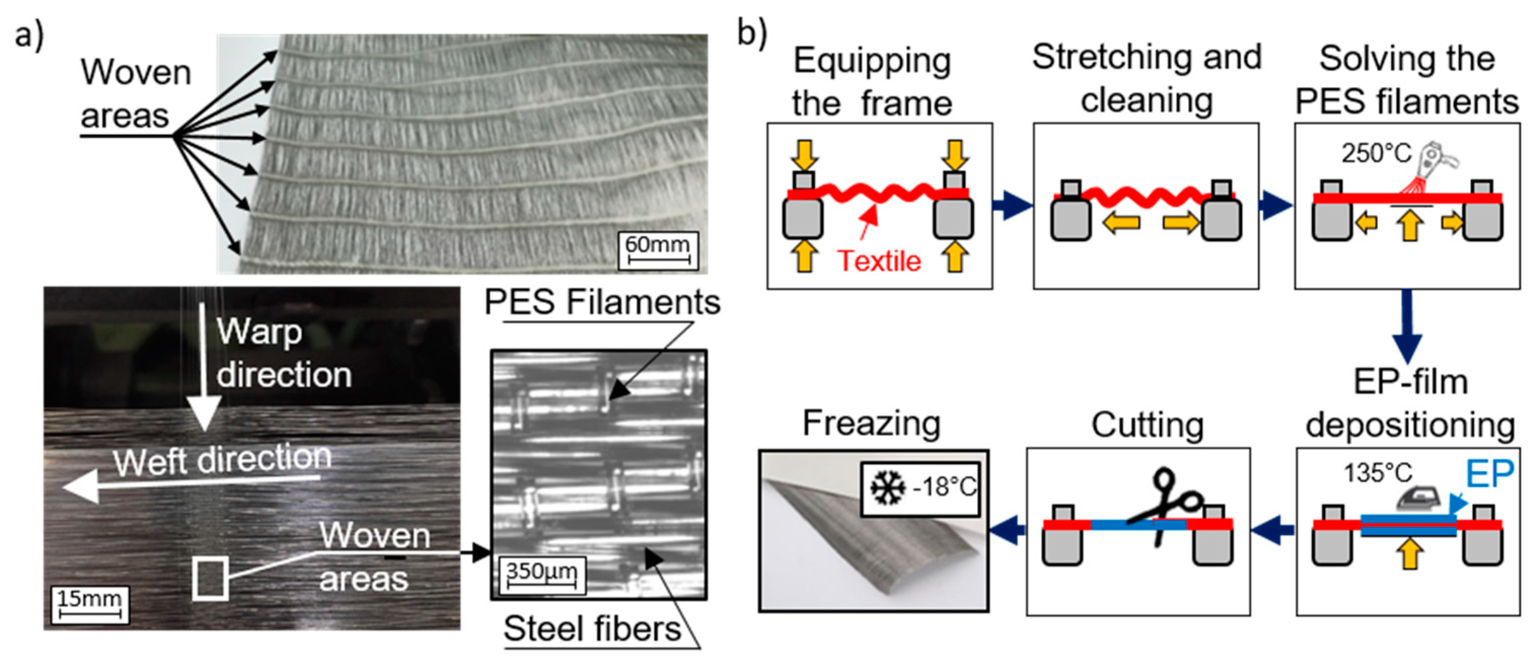
3.1. Laminate Manufacturing

The different laminate configurations are manufactured by manually stacking the pre-impregnated fiber reinforced textiles and a subsequent curing process in an autoclave. Because no pre-impregnated steel fiber textiles are currently available, the first step was to combine a steel fiber textile with thin resin films (Type: Cycom 977-2-40). The dry steel fiber fabric used is a quasi-unidirectional fabric structure (see Figure 2a; area weight: 440 g/m2) and has been developed in cooperation with GKD.
Compared to other manufacturing and hybridization methods used so far, such as fiber winding [17] or dry fiber placement [52], the use of this quasi-unidirectional fabric simplifies the semi-finished products handling and thus increases the efficiency of the manufacturing while maintaining a high level of reproducibility. The fabric consists of single drawn steel fibers (1.4301; diameter: 75 µm, supplied by Bekaert) in the weft direction (size approx. 250 mesh) and frequently repeating areas of woven polyethersulfone (PES) filaments (diameter: 90 µm) in the warp direction. The frequently repeating woven areas have a width of about 10 mm, while the distance between them is approximately 50 mm. The manufacturing process of the pre-impregnated steel fiber textile (see Figure 2b) started by fixing the fabric on a frame and stretching it until the fibers were aligned parallel to each other. To reduce the undulations caused by the fabric structure, the PES filaments were heated up to 250 °C in the next step. At the same time, the pretension of the steel fiber textile was slowly increased. This dissolves the PES filaments and significantly reduces the degree of undulation. Then, the resin films were applied on both sides of the fabric, heated up to 135 °C for a short time period (t < 2 min) and simultaneously pressed onto the fabric. The short-term heating reduces the viscosity of the resin and, in combination with the manually applied pressure, enables pre-impregnation of the steel fiber fabric. In the next step, the pre-impregnated steel fiber textiles and the pre-impregnated carbon fibers (type: Cycom 977-2-35-12KHTS-134) were sliced into panel-sized pieces (350 × 350 mm) and stacked according to the desired stacking sequence (see Table 1). In addition, peel fabrics (Tygavac 60BR) were applied to the top and bottom of the panels. Then the panels were fixed in the panel tooling and sealed with polyimide adhesive tape to prevent resin loss during curing. This setup is provided with venting fabrics, packed in a vacuum bag, evacuated (<10 mbar) and cured an autoclave. The curing cycle included a one-hour dwell time at 135 °C followed by a three-hour cure time at 180 °C. The heating and cooling rates used were 2 °C/min. A pressure of 6.5 bar was applied from the beginning of the dwelling stage until the end of the curing cycle. During the initial heat-up, the resin viscosity decreased and reached its minimum at approximately 135 °C. By interrupting the heating at this temperature, further cross-linking of the epoxy resin was delayed. The low viscosity facilitated impregnation and consolidation of the laminates as well as removal of entrapped air. This is particularly important for the pre-impregnated steel fiber textiles. Applying this procedure, the panels listed in Table 1 were manufactured. Figure 3 shows exemplary micrographs of the manufactured laminates.

3.2. Specimen Preparation and Test Setup

The test specimens listed in Table 2 were retrieved from the manufactured panels using a circular saw and fitted with end tabs to improve the load introduction by the hydraulic clamping device of the testing machine. The tests were performed with a Zwick/Roell Z250 servo-electric testing machine. The force was measured using a load cell with a calibrated measuring range between 500 N and 250 kN. In addition to the testing machine’s deformation measurement system, specimen surface deformations were captured by a three-dimensional digital image correlation (DIC) system. Data acquisition during the test starts when a force threshold of 100 N is exceeded and ends when the force falls below this threshold. The measured forces and deformations are evaluated based on stresses and strains. Therefore, the forces are related to the initial cross-section area, and the deformations are related to the initial gauge length of the specimen. Each laminate configuration is tested in a series of 10 specimens under laboratory conditions at room temperature (23 °C).

4. Numerical Predictions and Model Validation

To assess the predictability of the material behavior of SCFRP using the laminated shell strategy, three steps were performed. In the first step, the parameters of the material model are adjusted. This adjustment process is based on the results of the tensile and shear tests on the pure CFRP and SRP specimens (see Table 2 column: Purpose) and enables the best possible mapping of the mechanical behavior of the single layers in the hybrid laminates. Based on these parameterized material models, the second step demonstrates the application of the laminated shell strategy for the numerical prediction of the material behavior of SCRP laminates. In the third step, the numerical predictions are validated by comparing them with experimental results of the unidirectional and multidirectional reinforced SCFRP specimens (see Table 2 column: Purpose). The numerical analyses presented in this study were performed using the following FEA-model setup (see Figure 4):
  • The numerical investigations were performed using the explicit solver LS-Dyna.
  • The sample geometries were modeled with rectangular, fully integrated shell elements (LS-Dyna element type 16) [53]. The element size was varied as described in the following sections.
  • The degrees of freedom of the nodes belonging to the shell elements were locked in the area of the fixed clamping, and a prescribed displacement was set in the area of the load introduction.
  • In order to be able to determine a structural response comparable to the experimental results, force sensors in the cross section and displacement sensors were modeled at the clamping areas of the sample geometry.
  • The mapping of the experimentally investigated laminate structures was carried out using the laminated shell strategy using the *PART_COMPOSITE method of LS-Dyna (see Figure 4).
  • The material model *MAT_LAMINATED_COMPOSITE_FABRIC [53] implemented for LS-Dyna was used in combination with the failure criterion according to HASHIN [54] to represent the material behavior of CFRP layers. The material behavior of the SFRP layers was mapped with the material model described in chapter 2.

4.1. Material Model Parameterization

Because the used material models contain phenomenological description approaches, the material model parameters cannot be derived directly from the experimental results. Instead, the material model parameters were determined using a parameter-fitting process. This involved comparing the numerical predictions with the corresponding experimental results and systematically adjusting the material model parameters until the numerical prediction shows the best possible mapping. This was realized in an automated process using a parameter-fitting method implemented in LS-Opt. The comparison between the experimentally determined stress–strain curves on the pure CFRP and SFRP specimens and the result of the parameter fitting are shown in Figure 5. The mechanical properties of the best-fitting numerical result and the experimental results are listed in Table 3.
When subjected to tensile loading parallel to the fiber orientation (see Figure 5a), CFRP exhibits linear elastic, brittle material behavior. In contrast, pure SFRP shows a pronounced ductility with a significant higher elongation at break and a lower strength and stiffness. This results directly from the different material properties of the reinforcement fibers. When loaded transverse to the fiber direction (see Figure 5b), both SFRP and CFRP exhibit nearly linear stress–strain behavior. Compared to CFRP, SFRP shows higher stiffness, lower strength and elongation at break transverse to the fiber direction. The reasons for these differences can be attributed, on the one hand, to the different degrees of isotropy for steel and carbon fibers, which explain the difference in stiffness. On the other hand, it is assumed that the interface strength between the unseized steel fiber surface and the matrix is comparatively low and thus explains the differences in strength and elongation at break. Similar influences can also be assumed in the shear test. The results of a shear test (see Figure 5c) on CFRP and SFRP show a pronounced nonlinear material behavior. Despite the higher shear stiffness of the steel fibers, CFRP exhibits a higher shear stiffness and shear strength. The reason for this unexpected behaviour is also assumed to follow from the lower level of adhesion between the unseized steel fiber surface and the matrix. In general, the fitting results show very good agreement with the experimental results and prove the already known mapping ability of the MTL model. This is also true for the newly implemented material model when it comes to the mapping for the SFRP material behavior in fiber direction. The largest remaining deviations occurred in the mapping of the transition from the elastic to the elastic–plastic section of the stress–strain curve and lead to a slight overestimation of the yield stress and to a slight underestimation of the material failure.

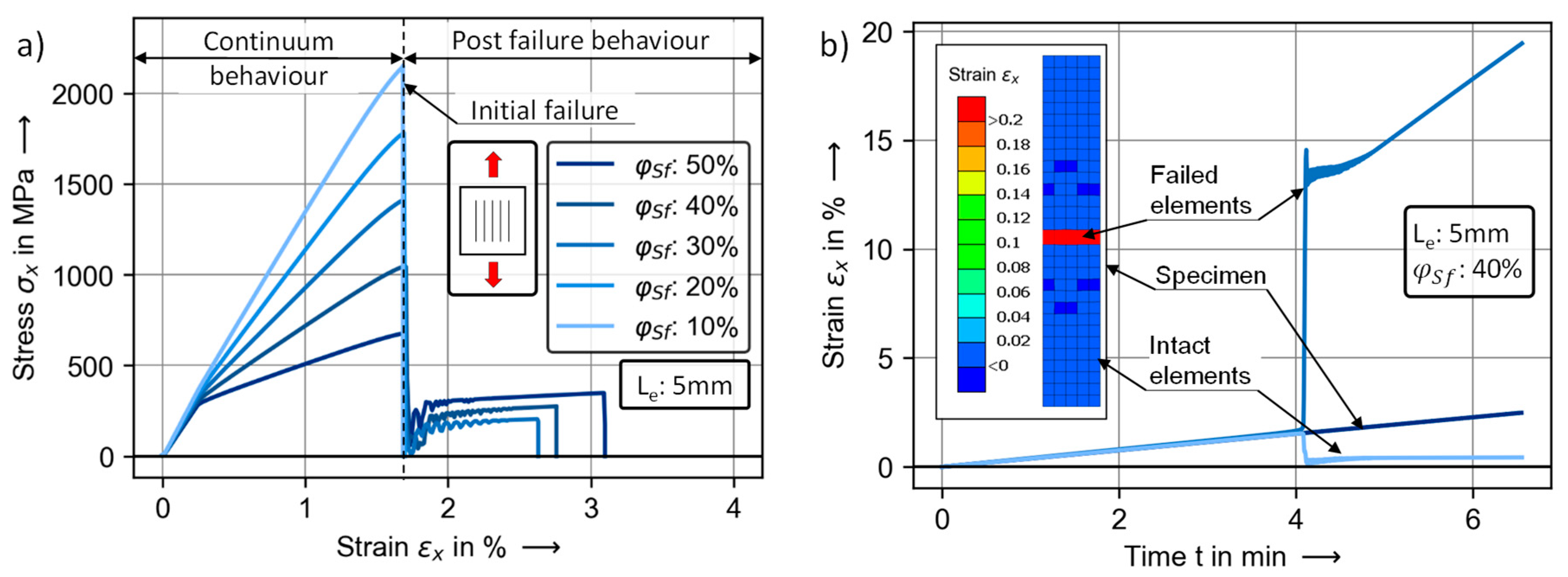
4.2. Prediction of the SCFRP Material Behavior in FEA

To demonstrate the possibilities and limitations of the proposed modeling approach, the calibrated material models for CFRP and SFRP are used to predict the stress–strain behavior of tension-loaded unidirectional reinforced hybrid SCFRP laminates. For this purpose, various simulation models were built considering different steel fiber volume fractions and different element sizes. The total fiber volume fraction was fixed to 60 vol.%. The respective steel and carbon fiber volume fractions were adjusted by the number of corresponding individual layers in the laminate structure. A variation of the steel fiber volume fraction is therefore equivalent to a reciprocal variation of the carbon fiber volume fraction. The resulting stress–strain curves of these variations (see Figure 6a) can be divided into two sections.
The first section represents the continuum material behavior of the intact material and ends with the initial failure of the carbon fibers. Its characteristic bilinear stress–strain behavior can be attributed to the transition of the SFRP layers from a purely elastic to an elastic–plastic material behavior. Thus, the intensity of the bilinearity increases with rising steel fiber volume fraction. The second section of the material behavior occurs only for specific steel fiber volume fractions. Here, a so-called post-failure behavior is observed after the failure of the carbon fiber. The stress level and the maximum elongation in the post-failure behavior increase with the steel fiber volume fraction. The distinctive initial failure of the carbon fibers shows up as a local effect within a single row of elements across the cross-section of the simulation models (see Figure 6b). In these elements, there is a sudden increase in strain at the time of the initial failure, while the strains in the intact elements suddenly drop. The associated node movement of the initially damaged elements represents a relative displacement. The intensity of the sudden strain increase in the damaged elements depends on the load drop after the initial failure, which is related to the number of failed CFRP layers in the laminate structure and thus to the steel fiber volume fraction and the edge length of the elements. The smaller the edge length of the elements or the smaller the steel fiber volume content, the greater the relative displacement and the greater the sudden increase in strain in the damaged elements (see Figure 7a,b). Regarding the occurrence of a post-failure behavior, the sudden strain increase during the initial failure must be resisted by the steel fibers. For a SCFRP configuration with a steel fiber volume fraction of 40 vol.% and an element edge length of 3 mm, the strain increase is higher than the elongation at break of the SFRP layer. Accordingly, the initial failure is coupled with the brittle material failure of the laminate. For higher element edge lengths, the initial failure can be exceeded and a post-failure behavior occurs (see Figure 7c). The strain states within the post-failure behavior are inhomogeneous and follow the stiffness ratio between the damaged and intact elements. With the exception of SCFRP laminates with very high steel fiber volume fractions, strain increases in the post-failure behavior occur mainly in the damaged elements (see Figure 6b). Therefore, the elongation at break of the entire SCFRP laminate depends on the remaining strain capacity of the SFRP layers in the damaged elements after the initial failure and the edge length of these elements. The dependency between the post-failure behavior and the element geometry is a well-known problem in mapping the softening behavior using an element-wise discretized geometry and is formally known as the localization effect.
In general, the stress–strain behavior of SFRP layers during initial failure is influenced by hardening. Higher sudden strain increases are associated with higher stress increases due to hardening (see Figure 7b,d). Furthermore, relative displacement during initial failure is associated with dampened translational oscillation. Here, it can be observed that higher load drops after the initial failure lead to a higher first amplitude in the oscillation (see Figure 7a,b). Depending on the steel fiber volume fraction and the length of the element edge, the oscillation can induce one or more hystereses in the SFRP layers (see Figure 7d).

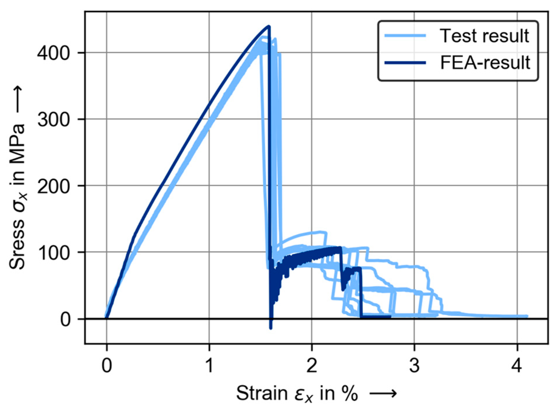
4.3. Validation of the Numerical Predictions

To evaluate the mapping capability of the presented approach, the experimental results of the unidirectional and multidirectional reinforced SCFRP laminates are compared with corresponding numerical predictions. As the element edge length has a significant influence on the numerical prediction of post-failure behaviour—in addition to the fiber volume fractions and laminate layup—the size of the initial damage area that occurs in the experiment after the initial failure is also adjusted in the model setup. In (Figure 8a,b), the numerical predictions are compared to the experimental results for the unidirectional reinforced hybrid laminates. The corresponding properties are listed in Table 4. In the first section of the material behavior, the numerical predictions achieve a good mapping of the experimental results. Smaller deviations are observed in the prediction of the transition point in the bilinear stress–strain behavior. Besides a slight overestimation of the material strength, the point of initial failure is also predicted with very good accuracy.
Similar to the results of numerical predictions, the initial failure in the experimental results is coupled with the occurrence of a local damage. It is assumed that the failure of the carbon fiber occurs in this area and causes delamination between the SFRP layers and the CFRP layers. As in the numerical predictions, the corresponding drop in stiffness causes a relative displacement between the intact and the damaged area of the specimen, leading to a sudden increase in strain (see Figure 8c). Regarding the prediction of the stress level in the post-failure behavior, the numerical prediction also achieves very good mapping. However, when it comes to the elongation at break, the numerical predictions become inaccurate, especially for laminates with high steel fiber volume fractions. The numerical prediction for the laminate configuration with a steel fiber volume fraction of approx. 45% and an element edge length of 16 mm leads to a significant underestimation of the elongation at break. Higher accuracy is reached for the laminate configuration with a steel fiber volume fraction of approx. 30% and an element edge length of 25 mm. This results from the limitation of the initial damage area by the element size of the numerical predictions. While the initial damage area in the experiment propagates during further loading, the initial damaged area in the numerical prediction is limited to the geometry of the initially damaged elements (see Figure 8d). This leads to an overestimation of the strain state in the damaged elements and thus to an underestimation of the elongation at break. This applies in particular when the initial size of the damaged area occurring in the experiments is small compared to its size during the propagation.
In the context of future design tasks, the interaction of unidirectional oriented steel fibers with multidirectional oriented hybridization partners is of significance in addition to the modeling of unidirectional material behavior. Therefore, the tensile test result of the multidirectional SCFRP laminate is compared with a corresponding numerical prediction (see Figure 9 and Table 5). As before, the modeling of the experimental test setup takes into account not only the fiber volume fractions and the laminate layup, but also the size of the initial damaged area occurring in the test. In this regard, an element edge length of approx. 12 mm is used (experimental average: 11.45 mm).
The resulting numerical prediction for the multidirectional SCFRP laminate shows a good mapping of the material behavior before initial failure as well as within the post-failure behavior. In particular, with regard to the predicted stress level of the post-failure behavior, it can be observed that in addition to the SFRP layer oriented in 0°, the CFRP layers oriented in ±45° are also involved in the load contribution after the initial failure. The good mapping result between the experimental and the predicted stress level in the post-failure behavior suggests that this also occurs in the experiments.

5. Conclusions

This work is dedicated to the development and evaluation of a description method for MFH for use in FEA. For this purpose, numerical predictions for the material behavior of hybrid SCFRP using the laminated shell strategy were performed and evaluated. Regarding the description of the complex material response of metal fiber reinforcement polymers, a material model combining an orthotropic damage model and a 1D plasticity model was developed and implemented as a user-defined subroutine for LS-Dyna. Furthermore, steel and carbon fiber reinforced composites were manufactured and used for the parameterization and validation of numerical predictions. For SCFRP with a sufficiently high steel fiber content, the occurrence of an initial failure and the associated relative displacement is a characteristic mechanism in the material behavior. In this study, it is shown that the model using the laminated shell strategy in combination with the adapted material model is capable of describing this mechanism. The material reactions of the SFRP layers associated with the initial failure show a physically plausible mechanical behavior and characterize the progress achieved in the field of describing the material behavior of MFH. However, the drawback is the dependence between the element size and the accuracy in predicting the post-failure behavior due to the well-known effect of strain localization. In terms of validation of numerical predictions for SCFRP, a good mapping for the behavior up to initial failure is reached. The numerical predictions of the post-failure behavior show an underestimation for laminates with high steel-fiber volume fractions. The reason for the underestimation arises from the limitation of the numerical model to element sizes. Because the element size must be adjusted to the geometric size of the initial damage area occurring in the experiments, a prediction method for the size of the initial damaged area is needed to consider MFH such as SCFRP within numerically aided component design.

Author Contributions

J.R.: conceptualization; investigation; formal analysis; validation; writing—original draft preparation; C.A.: conceptualization; writing—review and editing; S.S.: writing—review and editing; supervision; project administration; U.P.B.: supervision; project administration; funding acquisition. All authors have read and agreed to the published version of the manuscript.

Funding

The German Research Foundation provided financial support for this study (DFG, BR 4252/2-2).

Data Availability Statement

The datasets used during the current study are available from the corresponding author on reasonable request.

Acknowledgments

The steel fibers used in this study has been supplied by Bekaert and the quasi-unidirectional steel fiber fabric has been developed in cooperation with GKD Gebr. Kufferath AG.

Conflicts of Interest

The authors declare no conflict of interest.

References

  1. Rao, S.; Daniel, I.M.; Gdoutos, E.E. Mechanical Properties and Failure Behavior of Cord/Rubber Composites. Appl. Compos. Mater. 2004, 11, 353–375. [Google Scholar] [CrossRef]
  2. Van den Abeele, F. Impact Damage Models for Steel Fibre Reinforced Composite Materials. Ph.D. Thesis, Universität Gent, Gent, Belgium, 2006. [Google Scholar]
  3. Meichsner, A.; Voll, N.; Maier, M. Experimentelle Und Numerische Untersuchung Des Deformations-Und Bruchverhaltens von Edelstahltextilverstärkten Kunststoffen Und LFT-Werkstoffen. Z. Kunstst. J. Plast. Technol. 2008, 5, 48–70. [Google Scholar]
  4. Schmeer, S.; Steeg, M.; Maier, M.; Mitschang, P. Metal Fibre Reinforced Composite–Potentialities and Tasks. Adv. Compos. Lett. 2009, 18, 096369350901800. [Google Scholar] [CrossRef] [Green Version]
  5. Hasselbruch, H.; Von Hehl, A.; Zoch, H.W. Properties and Failure Behavior of Hybrid Wire Mesh/Carbon Fiber Reinforced Thermoplastic Composites under Quasi-Static Tensile Load. Mater. Des. 2014, 66, 429–436. [Google Scholar] [CrossRef]
  6. Hannemann, B.; Backe, S.; Schmeer, S.; Balle, F.; Breuer, U.P. New Multifunctional Hybrid Polymer Composites Reinforced by Carbon and Steel Fibers. In Proceedings of the ICCM20, Copenhagen, Denmark, 19 July 2015. [Google Scholar]
  7. Lehmann, B.; Selvarayan, S.K.; Ghomeshi, R.; Gresser, G.T. Carbon Fiber Reinforced Composite–Toughness and Structural Integrity Enhancement by Integrating Surface Modified Steel Fibers. Mater. Sci. Forum 2015, 825–826, 32. [Google Scholar] [CrossRef]
  8. Mosleh, Y.; Clemens, D.; Gorbatikh, L.; Verpoest, I.; van Vuure, A.W. Penetration Impact Resistance of Novel Tough Steel Fibre-Reinforced Polymer Composites. J. Reinf. Plast. Compos. 2015, 34, 624–635. [Google Scholar] [CrossRef]
  9. Vanclooster, K.; Barburski, M.; Lomov, S.V.; Verpoest, I.; Deridder, F.; Lanckmans, F. Experimental Characterization of Steel Fibre Knitted Fabrics Deformability. Exp. Tech. 2015, 39, 16–22. [Google Scholar] [CrossRef]
  10. Breuer, U.P.; Hannemann, B.; Schmeer, S.; Balle, F.; Backe, S. Metal and Carbon—The Development of a New Multifuctional Material for Primary Structures. In Proceedings of the DLRK 2016, Brunswick, Germany, 13 September 2016. [Google Scholar]
  11. McBride, A.K.; Turek, S.L.; Zaghi, A.E.; Burke, K.A. Mechanical Behavior of Hybrid Glass/Steel Fiber Reinforced Epoxy Composites. Polymers 2017, 9, 151. [Google Scholar] [CrossRef] [PubMed] [Green Version]
  12. Brien, C.; Mcbride, A.; Zaghi, A.E.; Burke, K.; Hill, A. Mechanical Behavior of Stainless Steel Fiber-Reinforced Composites Exposed to Accelerated Corrosion. Materials 2017, 10, 772. [Google Scholar] [CrossRef] [Green Version]
  13. Swolfs, Y.; De Cuyper, P.; Callens, M.G.; Verpoest, I.; Gorbatikh, L. Hybridisation of Two Ductile Materials–Steel Fibre and Self-Reinforced Polypropylene Composites. Compos. Part. A Appl. Sci. Manuf. 2017, 100, 48–54. [Google Scholar] [CrossRef]
  14. Arun Prakash, V.R.; Jaisingh, S. Mechanical Strength Behaviour of Silane Treated E-Glass Fibre, Al-6061 and SS-304 Wire Mesh Reinforced Epoxy Resin Hybrid Composites. Def. Technol. 2018. [Google Scholar] [CrossRef]
  15. Backe, S.; Balle, F.; Hannemann, B.; Schmeer, S.; Breuer, U.P. Fatigue Properties of Multifunctional Metal- and Carbon-Fiber-Reinforced Polymers and Intrinsic Capabilities for Damage Monitoring. Fatigue Fract. Eng. Mater. Struct. 2018, 42, 143–151. [Google Scholar] [CrossRef] [Green Version]
  16. Truong, G.T.; Tran, H.; Choi, K.K. Tensile Behavior of On- and Off-Axis Carbon Fiber Reinforced Polymer Composites Incorporating Steel Wire Mesh. Mech. Mater. 2019, 137, 103131. [Google Scholar] [CrossRef]
  17. Hannemann, B. Multifunctional Metal-Carbon-Fibre Composites for Damage Tolerant and Electrically Conductive Lightweight Structures. Ph.D. Thesis, TU-Kaiserslautern, Kaiserslautern, Germany, 2017. [Google Scholar]
  18. Ahmed, T. Hybrid Composite Structures: Multifunctionality through Metal Fibres. Ph.D. Thesis, TU Delft, Delft, The Netherlands, 2009. [Google Scholar]
  19. Hübler, M.; Nissle, S.; Gurka, M.; Breuer, U.P. Fiber-Reinforced Polymers with Integrated Shape Memory Alloy Actuation: An Innovative Actuation Method for Aerodynamic Applications. CEAS Aeronaut. J. 2016, 7, 567–576. [Google Scholar] [CrossRef]
  20. Gurka, M.; Nissle, S.; Hübler, M.; Kaiser, M. Active Vortex Generator Deployed on Demand by Active Hybrid Composites From Shape Memory Alloys and Fiber Reinforced Polymers. In Proceedings of the ASME 2017, Snowbird, UT, USA, 18 September 2017; p. V001T08A001. [Google Scholar]
  21. Nissle, S.; Gurka, M. Characterization of the Load Transfer between Fiber Reinforced Composites and Shape Memory Alloys for Active Hybrid Structures. In Proceedings of the ECCM18, Athens, Greece, 25–28 June 2018. [Google Scholar]
  22. Hannemann, B.; Backe, S.; Schmeer, S.; Balle, F.; Breuer, U.P. Improved Mechanical and Electrical Properties of CFRP Multiaxial Laminates by Embedded Metal Fibers. In Proceedings of the ECCM16, Sevilla, Spain, 22–26 June 2016. [Google Scholar]
  23. Bauer, C.; Hannemann, B.; Glatt, E.; Schmeer, S. Micromechanical Simulation of a Multifunctional Hybrid Composite with Continuous Steel and Carbon Fiber Reinforcement. In Proceedings of the ACCE, Detroit, MI, USA, 6 September 2017. [Google Scholar]
  24. Raju, B.; Hiremath, S.R.; Roy Mahapatra, D. A Review of Micromechanics Based Models for Effective Elastic Properties of Reinforced Polymer Matrix Composites. Compos. Struct. 2018, 204, 607–619. [Google Scholar] [CrossRef]
  25. Sabuncuoglu, B.; Orlova, S.; Gorbatikh, L.; Lomov, S.V.; Verpoest, I. Micro-Scale Finite Element Analysis of Stress Concentrations in Steel Fiber Composites under Transverse Loading. J. Compos. Mater. 2015, 49, 1057–1069. [Google Scholar] [CrossRef]
  26. Swolfs, Y.; McMeeking, R.M.; Verpoest, I.; Gorbatikh, L. The Effect of Fibre Dispersion on Initial Failure Strain and Cluster Development in Unidirectional Carbon/Glass Hybrid Composites. Compos. Part. A Appl. Sci. Manuf. 2015, 69, 279–287. [Google Scholar] [CrossRef] [Green Version]
  27. Utzig, L.; Karch, C.; Rehra, J.; Hannemann, B.; Schmeer, S. Modelling and Simulation of Effective Strength of Hybrid Polymer Composites Reinforced by Carbon and Steel Fibres. J. Mater. Sci. 2017, 53, 667–677. [Google Scholar] [CrossRef]
  28. Jalalvand, M.; Czél, G.; Wisnom, M.R. Damage Analysis of Pseudo-Ductile Thin-Ply UD Hybrid Composites—A New Analytical Method. Compos. Part. A Appl. Sci. Manuf. 2015, 69, 83–93. [Google Scholar] [CrossRef] [Green Version]
  29. Marom, G.; Fischer, S.; Tuler, F.R.; Wagner, H.D. Hybrid Effects in Composites: Conditions for Positive or Negative Effects versus Rule-of-Mixtures Behaviour. J. Mater. Sci. 1978, 13, 1419–1426. [Google Scholar] [CrossRef]
  30. Rehra, J.; Hannemann, B.; Schmeer, S.; Hausmann, J.; Breuer, U.P. Approach for an Analytical Description of the Failure Evolution of Continuous Steel and Carbon Fiber Hybrid Composites. Adv. Eng. Mater. 2019, 21, 1800565. [Google Scholar] [CrossRef]
  31. Swolfs, Y.; Gorbatikh, L.; Verpoest, I. Fibre Hybridisation in Polymer Composites: A Review. Compos. Part. A Appl. Sci. Manuf. 2014, 67, 181–200. [Google Scholar] [CrossRef]
  32. Wu, G.; Yang, J.M. Analytical Modelling and Numerical Simulation of the Nonlinear Deformation of Hybrid Fibre–Metal Laminates. Model. Simul. Mater. Sci. Eng. 2005, 13, 413. [Google Scholar] [CrossRef]
  33. Matthews, F.L.; Davies, G.A.O.; Hitchings, D.; Soutis, C. Finite Element Modelling of Composite Materials and Structures; Elsevier: Amsterdam, The Netherlands, 2000; ISBN 978-1-85573-892-8. [Google Scholar]
  34. Soden, P.D.; Kaddour, A.S.; Hinton, M.J. Recommendations for Designers and Researchers Resulting from the World-Wide Failure Exercise. Compos. Sci. Technol. 2004, 64, 589–604. [Google Scholar] [CrossRef]
  35. Kaddour, A.S.; Hinton, M.J. Benchmarking of Triaxial Failure Criteria for Composite Laminates: Comparison between Models of ‘Part (A)’ of ‘WWFE-II’. J. Compos. Mater. 2012, 46, 2595–2634. [Google Scholar] [CrossRef]
  36. Deuschle, H.M.; Puck, A. Application of the Puck Failure Theory for Fibre-Reinforced Composites under Three-Dimensional Stress: Comparison with Experimental Results. J. Compos. Mater. 2013, 47, 827–846. [Google Scholar] [CrossRef]
  37. Callens, M.G.; De Cuyper, P.; Swolfs, Y.; Gorbatikh, L.; Verpoest, I. Hybridization of Ductile Steel Fibre and Self-Reinforced Composites. In Proceedings of the 9th International Conference on Composite Science and Technology ICCST, Sorrento, Italy, 24–26 April 2013; pp. 24–26. [Google Scholar]
  38. Callens, M.G. Development of Ductile Stainless Steel Fibre Composites. Ph.D. Thesis, KU Leuven, Leuven, Belgium, 2014. [Google Scholar]
  39. Gerberich, W.W. Fracture Mechanics of a Composite with Ductile Fibers. J. Mech. Phys. Solids 1971, 19, 71–87. [Google Scholar] [CrossRef]
  40. Chen, J.-F.; Morozov, E.V. A Consistency Elasto-Viscoplastic Damage Model for Progressive Failure Analysis of Composite Laminates Subjected to Various Strain Rate Loadings. Compos. Struct. 2016, 148, 224–235. [Google Scholar] [CrossRef]
  41. Chen, Y.; Zhao, Y.; Ai, S.; He, C.; Tao, Y.; Yang, Y.; Fang, D. A Constitutive Model for Elastoplastic-Damage Coupling Effect of Unidirectional Fiber-Reinforced Polymer Matrix Composites. Compos. Part. A Appl. Sci. Manuf. 2020, 130, 105736. [Google Scholar] [CrossRef]
  42. Ge, J.; He, C.; Liang, J.; Chen, Y.; Fang, D. A Coupled Elastic-Plastic Damage Model for the Mechanical Behavior of Three-Dimensional (3D) Braided Composites. Compos. Sci. Technol. 2018, 157, 86–98. [Google Scholar] [CrossRef]
  43. Johnson, A.F.; Pickett, A.K.; Rozycki, P. Computational Methods for Predicting Impact Damage in Composite Structures. Compos. Sci. Technol. 2001, 61, 2183–2192. [Google Scholar] [CrossRef] [Green Version]
  44. Ladeveze, P.; LeDantec, E. Damage Modelling of the Elementary Ply for Laminated Composites. Compos. Sci. Technol. 1992, 43, 257–267. [Google Scholar] [CrossRef]
  45. Ren, R.; Le, G.; Zhong, J.; Ma, D.; He, Q. Numerical Research on Elasto-Plastic Behaviors of Fiber-Reinforced Polymer Based Composite Laminates. Compos. Struct. 2019, 207, 364–372. [Google Scholar] [CrossRef]
  46. Xiao, X. A Coupled Damage-Plasticity Model for Energy Absorption in Composite. Int. J. Damage Mech. 2010, 19, 727–751. [Google Scholar] [CrossRef]
  47. Matzenmiller, A.; Lubliner, J.; Taylor, R.L. A Constitutive Model for Anisotropic Damage in Fiber-Composites. Mech. Mater. 1995, 20, 125–152. [Google Scholar] [CrossRef]
  48. Ramberg, W.; Osgood, W.R. Description of Stress-Strain Curves by Three Parameters. Available online: https://digital.library.unt.edu/ark:/67531/metadc54697/ (accessed on 10 December 2020).
  49. Ziegler, H. A Modification of Prager’s Hardening Rule. Quart. Appl. Math. 1959, 17, 55–65. [Google Scholar] [CrossRef] [Green Version]
  50. Schweizerhof, K.; Weimar, K.; Münz, T.; Rottner, T. Crashworthiness Analysis with Enhanced Composite Material Models in LS-DYNA- Merits and Limits. Available online: http://www.dynasupport.com/howtos/material/composite-models/composite_paper.pdf (accessed on 10 December 2020).
  51. Galántai, A. The Theory of Newton’s Method. J. Comput. Appl. Math. 2000, 124, 25–44. [Google Scholar] [CrossRef] [Green Version]
  52. Kühn, F.; Rehra, J.; May, D.; Schmeer, S.; Mitschang, P. Dry Fiber Placement of Carbon/Steel Fiber Hybrid Preforms for Multifunctional Composites. Adv. Manuf. Polym. Compos. Sci. 2019, 5, 37–49. [Google Scholar] [CrossRef]
  53. Hallquist, J.O. LS-DYNA Theory Manual-March 2006. 680. Available online: https://www.lstc.com/dynamat/pdfs/mat_104_theory.pdf (accessed on 20 July 2022).
  54. Hashin, Z. Failure Criteria for Unidirectional Fiber Composites. J. Appl. Mech. 1980, 47, 329–334. [Google Scholar] [CrossRef]
Figure 1. Flowchart of the sequential treatment of the plasticity and the damage model within the implemented material model.
Jcs 06 00235 g001
Figure 2. (a) Woven structure of the quasi-unidirectional steel fiber fabric; and (b) manufacturing process of the pre-impregnated steel fiber textiles.
Jcs 06 00235 g002
Figure 3. Micrographs of the SFRP_UD_L laminate in (a), the SCFRP_UD_30 laminate in (b), and the SCFRP_MD_20 laminate in (c).
Jcs 06 00235 g003
Figure 4. Overview of the FEA-model setup including the application of the laminated shell strategy and its linkage to the microstructure of the corresponding laminate.
Jcs 06 00235 g004
Figure 5. Experimentally determined stress–strain behavior and the result of parameter fitting for tensile tests of CFRP and SFRP in parallel to the fiber direction (CFRP_UD_L, SFRP_UD_L) (a), transverse to the fiber direction (CFRP_UD_T, SFRP_UD_T) (b) and for shear tests (CFRP_UD_S,SFRP_UD_S) (c).
Jcs 06 00235 g005
Figure 6. Variation of the steel fiber volume fraction in the FEA model with a fixed element edge length of 5 mm in (a) and local strain of an initially damaged and an intact element in the FEA model with 40 vol.% steel fibers and a fixed element edge length of 5 mm in (b).
Jcs 06 00235 g006
Figure 7. Sudden strain increase at the initial failure for different steel fiber volume fractions in (a) and for different element edge lengths in (b) and stress–strain behavior of a laminate configuration with a steel fiber volume fraction of 40% for a variation of the element edge length in (c) as well as stress–strain behavior of an SFRP layer in the initially damaged elements for different element edge lengths in (d).
Jcs 06 00235 g007
Figure 8. Experimentally determined and numerically predicted stress–strain behavior for the SCFRP_UD_30 specimens in (a) and the SCFRP_UD_45 specimens (b) in comparison of the elongation measured in the initial damage area with the elongation of the entire specimen during a tensile test of a SCFRP_UD_30 specimen in (c), and comparison of the damage evolution in the experiment and the initially damaged element in the calculation model for a SCFRP_UD_45 specimen in (d).
Jcs 06 00235 g008
Figure 9. Experimentally determined and numerically predicted stress–strain behavior for a multidirectional SCFRP with a steel fiber volume fraction of approx. 20%.
Jcs 06 00235 g009
Table 1. Manufactured laminate configurations, including their stacking sequence and volume fractions measured by fiber counting using a Hough transform-based circle detection.
LabelStacking SequenceMicrostructure
L = longitudinal; T = transvers; S = shear; UD = unidirectional; MD = multidirectional; 20, 30 or 45 = steel fiber volume fractionsf = steel fiber; cf = carbon fiber;
s = symmetric ;   x y ¯ = middle symmetric ply
Steel   fiber   volume   fraction   ( φ s f ) Carbon   fiber   volume   fraction   ( φ c f ) Resin   volume   fraction   ( φ r )
SFRP_UD_L [ ( 0 s f ) 4 ] s   58.92 vol.%0 vol.%41.08 vol.%
SFRP_UD_T [ ( 90 s f ) 8 ] s   59.48 vol.%0 vol.%40.52 vol.%
SFRP_SL_S [ ( + 45 s f / 45 s f ) 4 ] s   59.73 vol.%0 vol.%40.27 vol.%
CFRP_UD_L [ ( 0 c f ) 4 ] s   0 vol.%61.49 vol.%38.51 vol.%
CFRP_UD_T [ ( 90 c f ) 8 ] s   0 vol.%62.35 vol.%37.75 vol.%
CFRP_SL_S [ ( + 45 c f / 45 c f ) 4 ] s   0 vol.%60.16 vol.%39.84 vol.%
SCFRP_UD_30 [ ( 0 s f ) 2 / ( 0 c f ) 3 ] s   32.50 vol.%28.35 vol.%39.15 vol.%
SCFRP_UD_45 [ ( 0 s f ) 3 / ( 0 c f ) 2 ] s   45.39 vol.%18.40 vol.%36.21 vol.%
SCFRP_MD_20 [ ( 0 s f ) 2 / ( 90 s f ) 2 / ( + 45 c f / + 45 c f ) 2 / 90 c f / 0 c f / 90 ¯ c f ] s 18.36 vol.%40.89 vol.%40.75 vol.%
Table 2. Scope of testing as well as related standards, specimen geometries and testing parameters.
LabelFeasible TestsRelated StandardSpecimen Size (W × H × T)Gauge LengthTest SpeedPurpose
SFRP_L8DIN EN ISO 527-5250 × 15 × 11504 mm/minParametrization of the SFRP-Model
SFRP_T9DIN EN 2597150 × 10 × 2502 mm/min
SFRP_S8EN ISO 14,129250 × 25 × 21504 mm/min
CFRP_L8DIN EN ISO 527250 × 15 × 11502 mm/minParametrization of the CFRP-Model
CFRP_T9DIN EN 2597150 × 10 × 2502 mm/min
CFRP_S10EN ISO 14,129250 × 25 × 21504 mm/min
SCFRP_UD3010DIN EN ISO 527-5150 × 15 × 1502 mm/minValidation of the unidirectional prediction
SCFRP_UD4510DIN EN ISO 527-5150 × 15 × 1502 mm/min
SCFRP_MD10DIN EN ISO 527-4250 × 15 × 21502 mm/minValidation of the multidirectional prediction
Table 3. Experimentally determined and numerically predicted mechanical properties of CFRP and SFRP.
LabelResult Type E x
in GPa
E y
in GPa
G x y
in GPa
S t , x  
in MPa
S t , y  
in MPa
S x y  
in MPa
ε x  
in %
ε y  
in %
SFRPTest90.3 ± 5.412.4 ± 0.283.68 ± 0.09462 ± 6421.9 ± 2.751.8 ± 0.4220.6 ± 2.80.19 ± 0.04
Fitting93.712.953.7428.825.754.219.30.24
CFRPTest141.5 ± 4.89.1 ± 0.944.43 ± 0.142312 ± 11276.5 ± 5.679.5 ± 1.51.5 ± 0.041.01 ± 0.17
Fitting145.89.314.82550.1378.673.81.581.12
Table 4. Experimentally determined and numerically predicted mechanical properties for SCFRP laminate with a steel fiber volume fraction of approx. 30% and with approx. 45% (for property identification see Figure 8a).
LabelResult Type E x
in GPa
σ y i e l d
in MPa
σ i n i
in MPa
ε i n i
in %
σ p o s t
in MPa
ε t o t
in %
u x
in MPa
SCFRP UD30Test109.4 ± 0.02224.1 ± 18.91540 ± 10.91.68 ± 0.03131.3 ± 8.711.9 ± 3.923.46 ± 3.7
FEA110.65270.451635.451.58119.7311.222.85
SCFRP UD45Test97.8 ± 0.08195.1 ± 18.9912.4 ± 10.91.75 ± 0.09266.6 ± 30.917.8 ± 2.947.81 ± 9.8
FEA98.54210.64970.351.58261.957.4132.47
Table 5. Experimentally determined and numerically predicted mechanical properties for a multidirectional SCFRP with a steel fiber volume fraction of approx. 20%.
LabelResult Type E x
in GPa
σ y i e l d
in MPa
σ i n i
in MPa
ε i n i
in %
σ p o s t
in MPa
ε t o t
in %
u x
in MPa
SCFRP MD20Test40.12 ± 1.0681.5 ± 7.06412.2 ± 6.591.52 ± 0.0585 ± 8.523.14 ± 0.450.88 ± 0.33
FEA45.15120.56425.791.598.532.510.85
Publisher’s Note: MDPI stays neutral with regard to jurisdictional claims in published maps and institutional affiliations.

