Article

Influence of Thermal and Thermomechanical Stimuli on Dental Restoration Geometry and Material Properties of Cervical Restoration: A 3D Finite Element Analysis

1
Department of Mechanical and Industrial Engineering, Manipal Institute of Technology, Manipal Academy of Higher Education, Manipal 576104, Karnataka, India
2
Department of Conservative Dentistry and Endodontics, KVG Dental College & Hospital, Sullia 574327, Karnataka, India
3
Department of Oral Medicine and Radiology, Manipal College of Dental Sciences, Manipal, Manipal Academy of Higher Education, Manipal 576104, Karnataka, India
4
Department of Aeronautical and Automobile Engineering, Manipal Institute of Technology, Manipal Academy of Higher Education, Manipal 576104, Karnataka, India
5
Department of Mechanical Engineering, School of Automobile, Mechanical & Mechatronics Engineering, Manipal University Jaipur, Jaipur 303007, Rajasthan, India
6
Department of Prosthodontics, Manipal College of Dental Sciences, Mangalore, Manipal Academy of Higher Education, Manipal 576104, Karnataka, India
*
Authors to whom correspondence should be addressed.
J. Compos. Sci. 2023, 7(1), 6; https://doi.org/10.3390/jcs7010006
Submission received: 5 November 2022 / Revised: 4 December 2022 / Accepted: 28 December 2022 / Published: 30 December 2022
(This article belongs to the Special Issue Advanced Polymeric Composites and Hybrid Materials)

Abstract

:
Cervical restoration of a premolar tooth is a challenging task as it involves structural modification to ensure the functional integrity of the tooth. The lack of retention in the cervical area, with the cavity margins on dentin and the nonavailability of enamel, makes it challenging for restoration. The high organic content of dentin, along with its tubular structure and outward flow of fluid, make dentin bonding difficult to attain. The objective of this study is to evaluate the impact of thermal and thermomechanical stimuli on the geometry of dental restorations in the cervical region. In the present study, a three-layered restorative material made of glass ionomer cement, hybrid layer, and composite resin is considered by varying the thickness of each layer. Group 1 of elliptical-shaped cavities generates von Mises stress of about 14.65 MPa (5 °C), 41.84 MPa (55 °C), 14.83 MPa (5 °C and 140 N), and 28.89 MPa (55 °C and 140 N), respectively, while the trapezoidal cavity showed higher stress of 36.27 MPa (5 °C), 74.44 MPa (55 °C), 34.14 MPa (5 °C and 140 N), and 75.57 MPa (55 °C and 140 N), which is comparable to the elliptical cavity. The result obtained from the analysis helps to identify the deformation and volume change that occurs due to various real-time conditions, such as temperature difference and thermal stress. The study provides insight into the behavior of novel restorative materials of varied thicknesses and temperature levels through simulation.

1. Introduction

The primary function of teeth is biting, which involves the blending, cutting, and grinding of food to allow the tongue and oropharynx to shape it into a bolus that can be easily swallowed. The most common dental problem observed in children, teenagers, and older individuals is cervical cavities, which are caused primarily by a variety of factors such as oral bacteria, frequent snacking, consuming sugary beverages, inadequate tooth cleaning, and occlusal stresses due to wasting diseases [1]. Preparing a cavity at the neck of the tooth (junction of crown and root surface) is a typical form of treatment modality for restoration of cervical lesions for filling a cavity on the buccal and lingual surfaces (Class V cavities termed by Dr. G V Black) [2]. It is a crucial activity as the dental restorations should last long in the biological setting. Since the restorative material and the dental substrate have different material properties, dentists need to determine the anticipated mechanical performance of a restored tooth [3]. Mandibular teeth, especially those with high occlusal loading as seen by the presence of wear facets, have been observed to have a greater failure rate of class V restorations when high-modulus macro-filled materials are used [4]. Finite element analysis (FEA) studies have shown that varying the mechanical properties of restorations and the restoration/cavity anatomy leads to variations in the stress distribution patterns when the same boundary condition and mastication load are applied on occlusal regions for different models [4,5].
The incidence of class V lesions that are noncarious in nature is 31–58%. The location of the lesion can make it more challenging to accomplish a long-lasting and stable restoration, which is the fundamental challenge in restorative treatment [6]. Amalgam, resin composites, and glass ionomer cement are usually used to restore the cavity [7]. However, these restorative materials have shortcomings in their ability to sustain the thermal stress and temperature variations (between 0 °C to 67 °C) that possibly occur in the oral cavity. This can cause the contraction and expansion of the cavity after the consumption of hot or cold beverages [8]. The properties of the materials, the procedures, cavity design, and the influences of the thermal stress on the restored tooth will decide how effectively the material adheres to the tooth surface. Tensile stress is seen on the silver amalgam restorative material when cold liquid is consumed, while compression happens in the resin composite restorative material. The opposite phenomenon takes place when a hot liquid is drunk, putting compression on the amalgam but tensile stress on the composite [9].
FEA has recently been employed to simulate the clinical context in several biomechanical studies. The finite element assessment is increasingly used to model and simulate dental treatment procedures, including the procedures involved and their effects post-treatment [10]. The expense of in vitro and in vivo studies can be decreased, and research outcomes can be improved by using these virtual models and simulations [11]. FEA plays an important role in the assessment of relevant treatment procedures by performing force analysis and material evaluation and approximating the tooth geometry with a finite number of points, three-dimensional (3D) imaging, and mapping of the tooth topology [12]. Subsequently, structural and thermal stress, compression, and strain calculations are performed for the elemental body [13]. This study aims to evaluate the causal effect of thermal and thermomechanical stimuli on the thickness of dental restorative materials, geometry, and material properties of cervical restorations.

2. Materials and Methods

2.1. FE Model Generation

The three-dimensional (3D) model of an extracted premolar tooth is created from digital imaging and communications in medicine (DICOM) images obtained from cone beam computed tomography (CBCT). This study was approved by the institutional ethics committee (IEC No. 883–2018), and the study was performed in accordance with the ethical standards. All the procedures were performed as per the ethical guidelines laid down by the Declaration of Helsinki (2013). A three-dimensional reconstruction method was employed, and the generated model was imported in standard triangle language (STL) format for further modifications using the tool Ansys SpaceClaim 2021 R2 version. The solid body of the premolar tooth generated from the STL model is shown in Figure 1. Internal contours, curvature, and occlusal anatomy were refined using SpaceClaim layout editing tools. ANSYS Workbench 2021 R2 was used to perform FE analysis (Swanson ANSYS, Houston, Pennsylvania).

2.2. Cervical Cavity of a Premolar Tooth

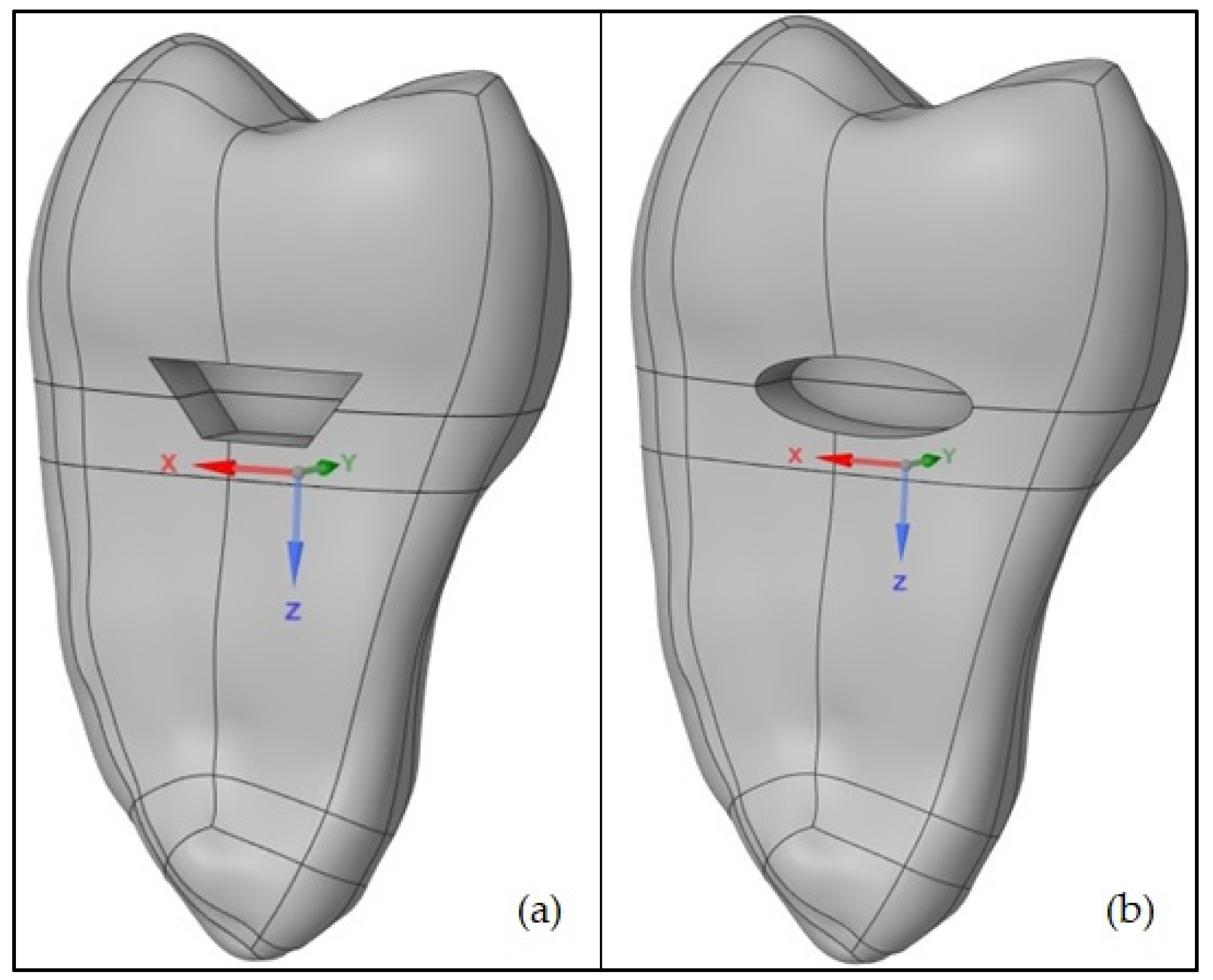
The two shapes of cavity considered in the present study for analysis included trapezoidal and elliptical-shaped symmetric cavities created in the cervical region (cementum–enamel junction (CEJ)) of a premolar tooth with a depth of 3 mm, a height of 2 mm, and a width of 6 mm. Technically, the cavity was restored with three materials: glass ionomer cement, hybrid layer, and composite resin. Figure 2a,b represent the images of trapezoidal and elliptical-shaped cavities, respectively.
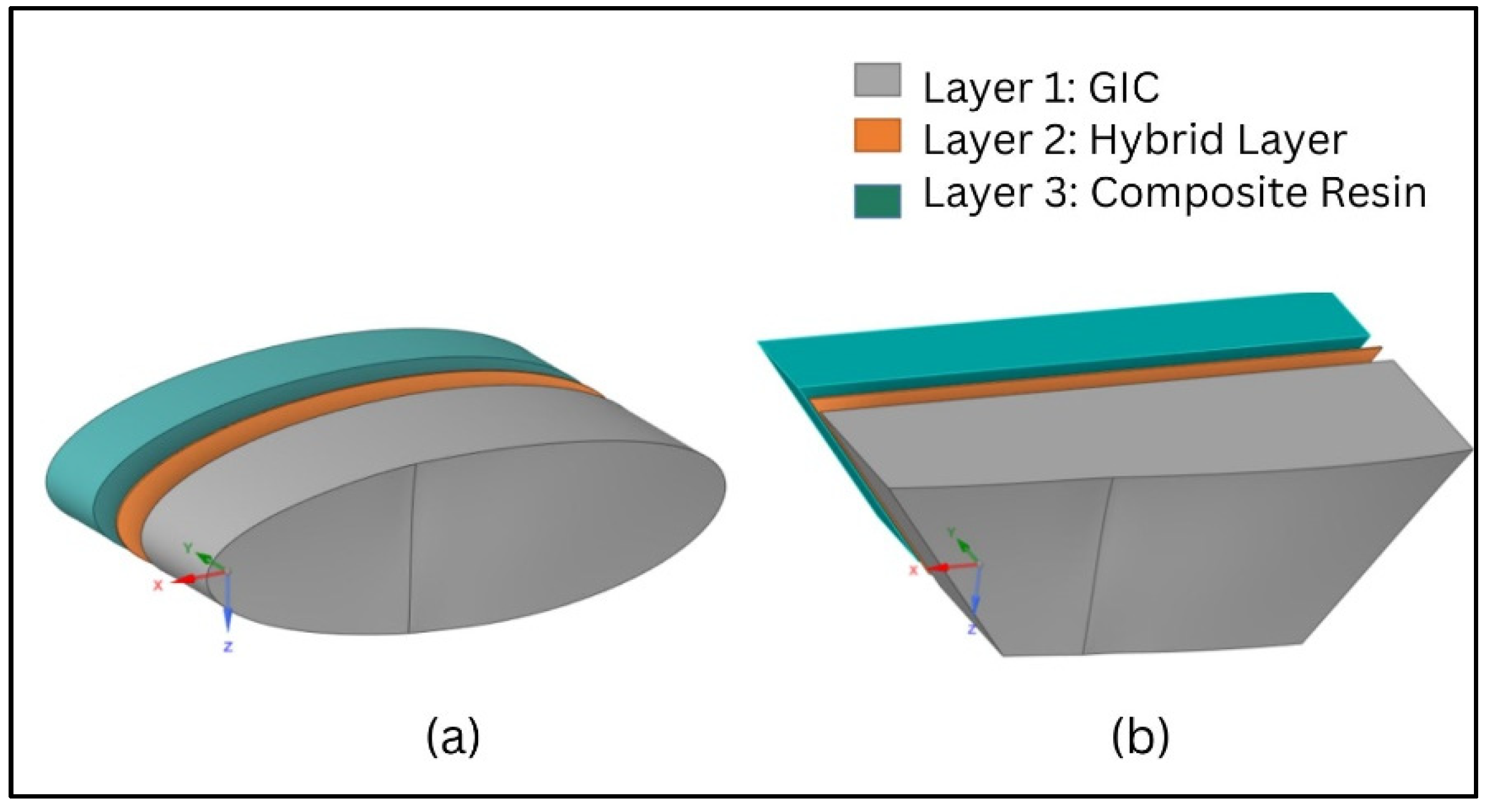
A prismatic cavity was created across the mesiodistal occlusal wall with a total depth of 3 mm. Layer 1 was at the rear part of the cavity made of GIC. The middle layer 2 was glued above layer 1 and was made of a hybrid layer, and the third layer was of composite resin. The thicknesses of the GIC, composite resin, and hybrid layer [14] were varied to study their response toward thermal and thermomechanical loading conditions. Figure 3a,b represent the filler materials used to restore the cavities [15].

2.3. Material Properties

The premolar tooth is divided into three regions, namely, enamel, dentin, and cementum. The enamel is thickest over the cusps, measuring 2.5 mm thick, and thins out near the cervical edges. The area around the cervical edges is called dentin. The cementum is a hard, calcified layer of tissue that covers the root of the tooth. On its outer side, the cementum is attached to the periodontal ligament, and on its inner side, the dentin. The materials and their properties used for finite element analysis are listed in Table 1.
The thermal and thermomechanical analysis were performed on trapezoidal and elliptical cavities by altering the thickness of each layer. Table 2 represents the division of groups according to the thickness of restorative material blocks considered in the present study [15,16,17,18].

2.4. Meshing

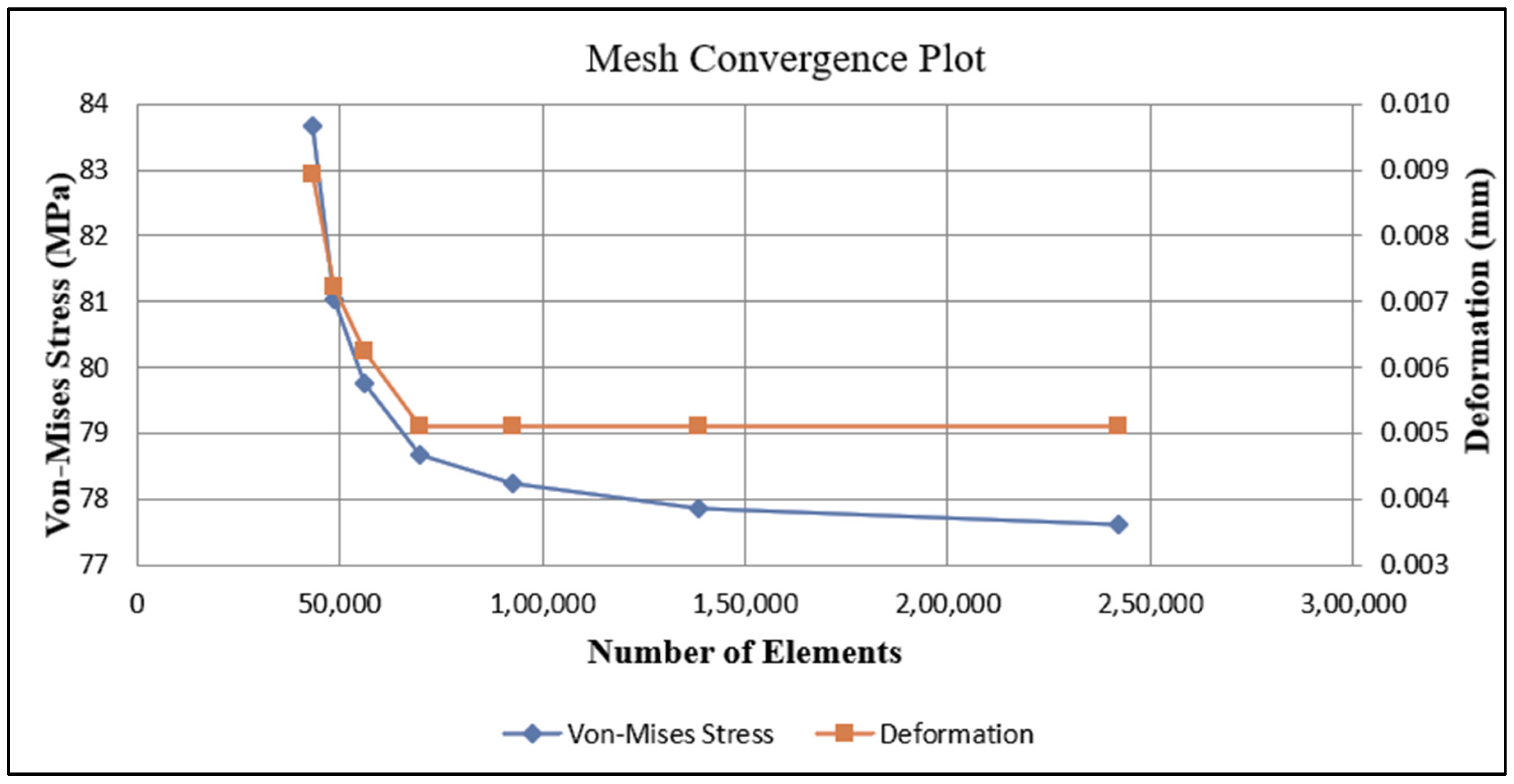
The CAD model with the restored cavity was exported to ANSYS Workbench 2021 R2 for meshing. Mesh was generated using tetrahedral elements used with adaptive mesh refinement. A mesh convergence test was performed to ensure that the results of the analysis were not affected by changing the mesh size. The test was conducted by varying the number of elements from 43,347 to 242,118. The coarse mesh was used outside the cavity region, and the finer mesh was used in the cavity region. Table 3 shows the results of the mesh convergence test.
The von Mises stress is a value used to predict whether the material will yield or fracture. The von Mises yield criterion states that if the von Mises stress of a material under load is equal to or greater than the yield limit of the same material under simple tension, then the material will yield or fracture. The evaluation of the von Mises stress is calculated using Equation (1):
( σ von   Mises ) ) 2 = ( σ 1 2 + σ 2 2 + σ 3 2   ) ( σ 1 σ 2 + σ 2 σ 3 + σ 3 σ 1 ) = ( σ y F O S ) 2
Figure 4 shows the plot of the mesh convergence test indicating the variation of von Mises stress and deformation observed for the variation in mesh density (number of elements). The mesh density was defined to be medium for outside the cavity region, while the finer mesh density was adopted at the cavity region. The “patch confirming method” was used as the algorithm, and the element order was set to “global settings”. A finer mesh of 0.2 mm was set in the cavity region. The “body sizing” feature was used to reduce the element size to 0.7 mm. Refinement of mesh was carried out to improve the element quality index. As a result, the model contained 105,872 nodes and 69,427 elements. The meshed models of trapezoidal and elliptical-shaped cavities and the restorative materials are shown in Figure 5a,b.

3. Results

3.1. Thermal Analysis on Trapezoidal Cavity at 5 °C

Thermal analysis was carried out in ANSYS Workbench 2021 R2. The “space claim” model was imported to ANSYS Workbench 2021 R2 through the “import” option. The materials and properties were assigned to the imported geometry. Bonded contact was defined between all mating parts. Enamel and dentin were subjected to a temperature of 5 °C (cold condition). A temperature of 35 °C (oral body temperature) was maintained at the cementum region, and all translational and rotational DOFs were constrained. This thermal analysis was performed on all six groups with various layer thicknesses. The von Mises stress and deformation observed for all six groups are shown in Table 4.
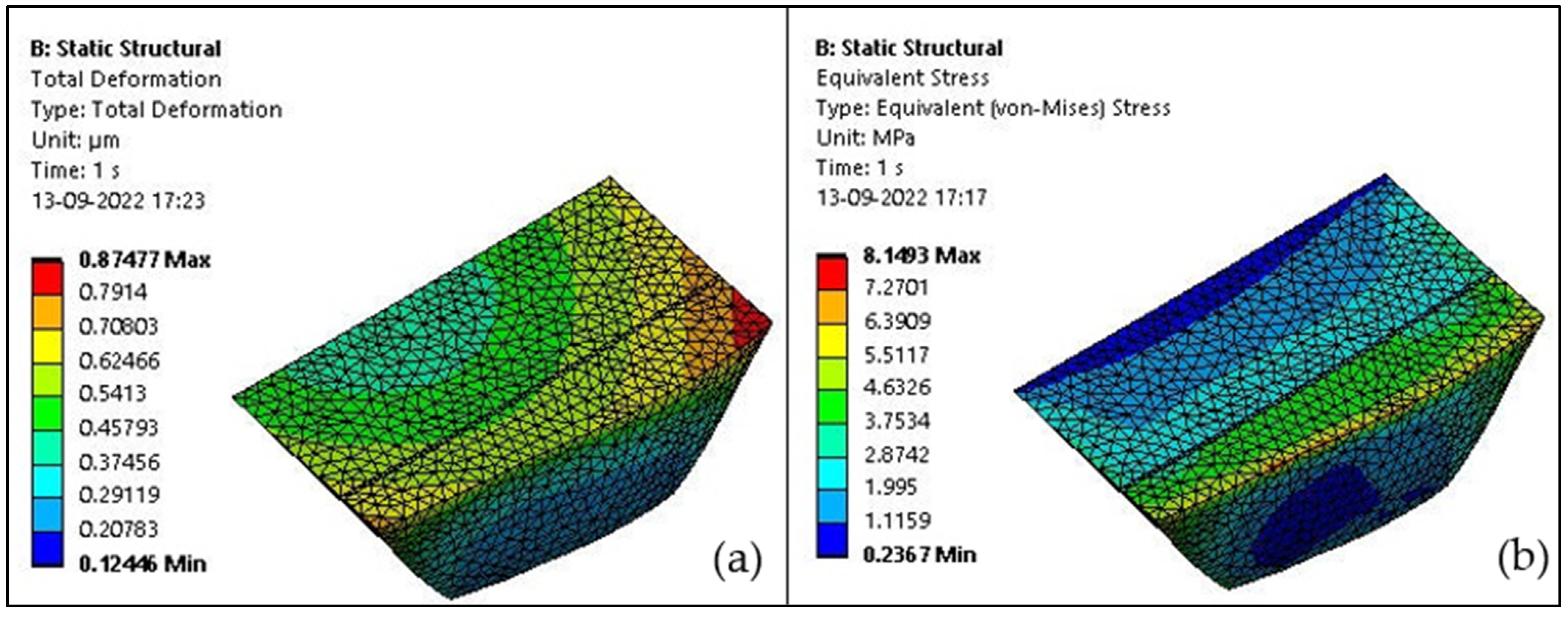
From the analysis, it is observed that at 5 °C, Group 1 shows the highest deformation and von Mises stress values, which are 2.363 μm and 36.276 MPa. It is also observed that Group 6 shows the least deformation and von Mises stress value, which are 0.874 μm and 8.149 MPa, as shown in Figure 6a,b.
The maximum deformation occurred at the upper right end of the cavity.

3.2. Thermal Analysis on Trapezoidal Cavity at 55 °C

Similarly, enamel and dentin were subjected to a temperature of 55 °C (hot condition). A temperature of 35 °C (oral body temperature) was maintained at the cementum region, and all translational and rotational degrees of freedom (DOF)s were constrained. This thermal analysis was performed on all six groups with various layer thicknesses. The von Mises stress and deformation observed for all six groups are shown in Table 5.
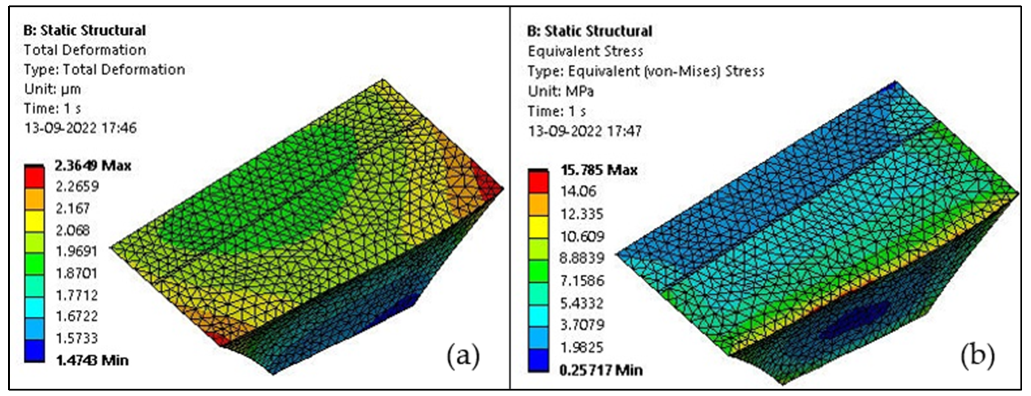
From the analysis, it is observed that at 55 °C, Group 1 shows the highest deformation and von Mises stress value, which are 5.2091 μm and 73.441 MPa. It is also observed that Group 6 shows the least deformation and von Mises stress value, which are 2.364 μm and 15.785 MPa, as shown in Figure 7a,b. The maximum deformation occurred at the upper right and left end of the cavity.

3.3. Thermomechanical Analysis on a Trapezoidal Cavity at 5 °C

The thermomechanical analysis was carried out in ANSYS Workbench 2021 R2. The “space claim” model was imported to ANSYS Workbench. The materials and properties were assigned to the imported geometry. Bonded contact was defined between all mating parts. Enamel and dentin were subjected to a temperature of 5 °C (cold condition). A temperature of 35 °C (oral body temperature) was maintained at the cementum region, and all translational and rotational DOFs were constrained. A 140 N concentrated load was applied perpendicular to the lingual plane of the buccal cusp on the occlusal surface (normal load) to simulate the chewing force. This thermomechanical analysis was performed on all six groups with various layer thicknesses. The von Mises stress and deformation observed for all six groups are shown in Table 6.
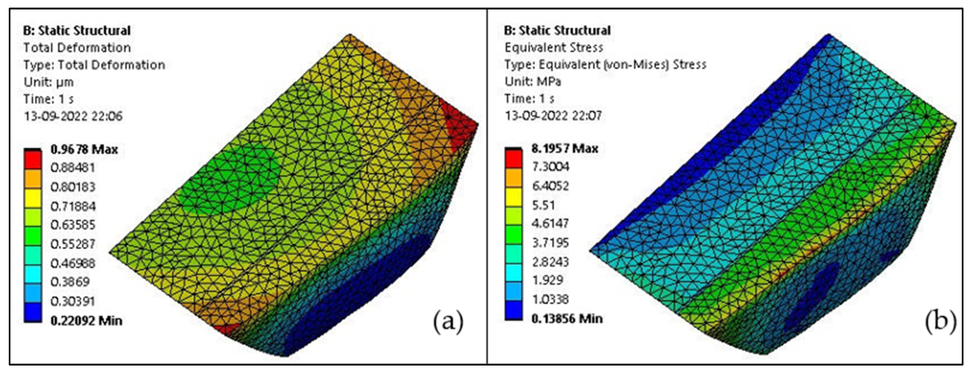
From the analysis, it is observed that at a temperature of 5 °C and loading of 140 N, Group 1 shows the highest deformation and von Mises stress value, which as 2.471 μm and 34.147 MPa. It is also observed that Group 6 shows the least deformation and von Mises stress value, which are 0.967 μm and 8.196 MPa, as shown in Figure 8a,b. The maximum deformation occurred at the upper right and left end of the cavity.

3.4. Thermomechanical Analysis on a Trapezoidal Cavity at 55 °C

Similarly, enamel and dentin were subjected to a temperature of 55 °C (hot condition). A temperature of 35 °C (oral body temperature) was maintained at the cementum region, and all translational and rotational DOFs were constrained. A 140 N concentrated load was applied perpendicular to the lingual plane of the buccal cusp on the occlusal surface (normal load) to simulate the chewing force. This thermomechanical analysis was performed on all six groups with various layer thicknesses. The von Mises stress and deformation observed for all six groups are shown in Table 7.
From the analysis, it is observed that at a temperature of 55 °C and loading of 140 N Group 1 shows the highest deformation and von Mises stress value, which are 5.123 μm and 75.572 MPa. It is also observed that Group 6 shows the least deformation and von Mises stress value, which are 2.191 μm and 15.174 MPa, as shown in Figure 9a,b. The maximum deformation occurred at the upper middle, right, and left end of the cavity.

3.5. Thermal Analysis on Elliptical Cavity at 5 °C

Thermal analysis was carried out in ANSYS Workbench 2021 R2. The “space claim” model was imported to ANSYS Workbench through the “import” option. The materials and properties were assigned to the imported geometry. Bonded contact was defined between all mating parts. Enamel and dentin were subjected to a temperature of 5 °C (cold condition). A temperature of 35 °C (oral body temperature) was maintained at the cementum region, and all translational and rotational DOFs were constrained. This thermal analysis was performed on all six groups with various layer thicknesses. The von Mises stress and deformation observed for all six groups are shown in Table 8.
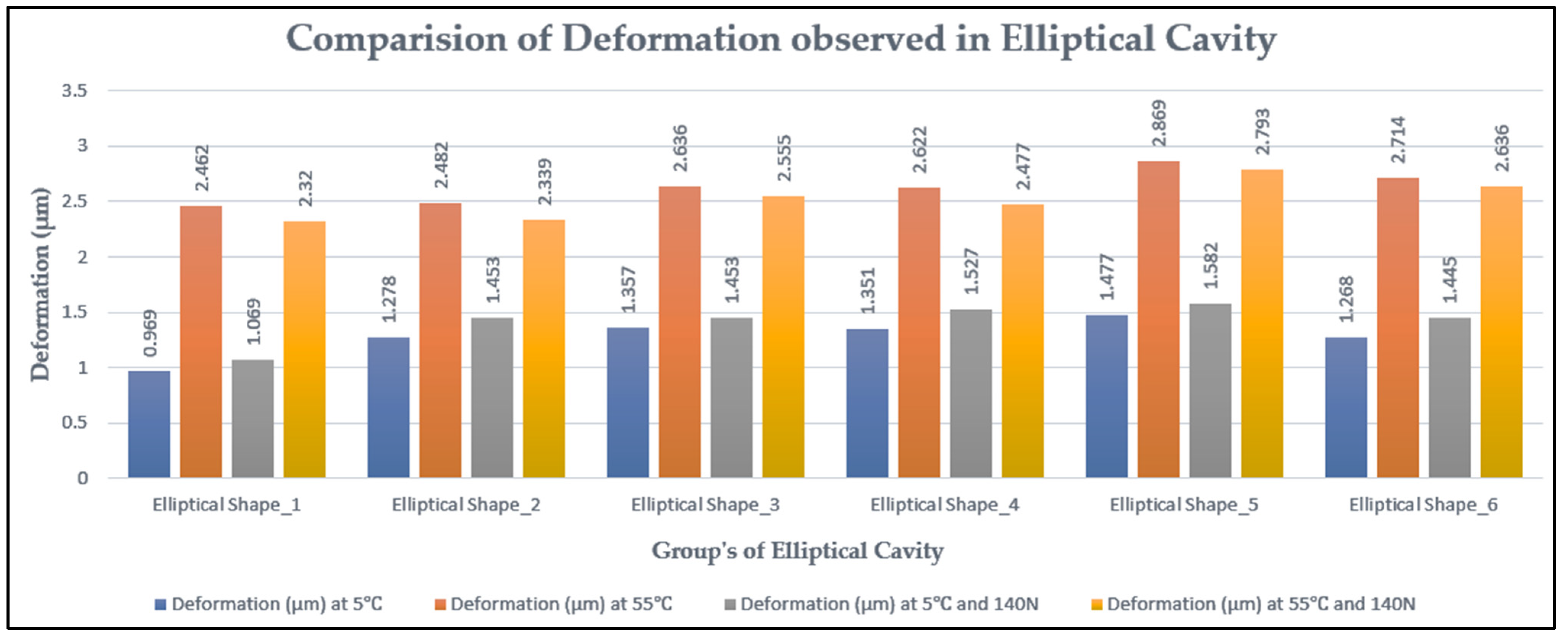
From the analysis, it is observed that at 5 °C Group 5 shows the highest deformation and von Mises stress value, which are 1.477 μm and 27.899 MPa. It is also observed that Group 1 shows the least deformation and von Mises stress value, which are 0.969 μm and 14.657 MPa, as shown in Figure 10a,b. The maximum deformation occurred at the upper right end of the cavity.

3.6. Thermal Analysis on Elliptical Cavity at 55 °C

Similarly, enamel and dentin were subjected to a temperature of 55 °C (hot condition). A temperature of 35 °C (oral body temperature) was maintained at the cementum region and all translational, and rotational DOFs were constrained. This thermal analysis was performed on all six groups with various layer thicknesses. The von Mises stress and deformation observed for all six groups are shown in Table 9.
From the analysis, we can observe that at 55 °C Group 5 shows the highest deformation and von Mises stress value, which are 2.869 μm and 54.156 MPa. We can also observe that Group 1 shows the least deformation and von Mises stress value, which are 2.462 μm and 32.331 MPa, as shown in Figure 11a,b. The maximum deformation occurred at the upper right end of the cavity.

3.7. Thermomechanical Analysis on Elliptical Cavity at 5 °C

The thermomechanical analysis was carried out in ANSYS Workbench 2021 R2. The “space claim” model was imported to ANSYS Workbench through the “import” option. The materials and properties were assigned to the imported geometry. Bonded contact was defined between all mating parts. Enamel and dentin were subjected to a temperature of 5 °C (cold condition). A temperature of 35 °C (oral body temperature) was maintained at the cementum region, and all translational and rotational DOFs were constrained. A 140 N concentrated load was applied perpendicular to the lingual plane of the buccal cusp on the occlusal surface (normal load) to simulate the chewing force. This thermomechanical analysis was performed on all six groups with various layer thicknesses. The von Mises stress and deformation observed for all six groups are shown in Table 10.
From the analysis, it is observed that at a temperature of 5 °C and loading of 140 N, Group 5 shows the highest deformation, and von Mises stress value is 1.582 μm and 28.886 MPa. It is also observed that Group 1 shows the least deformation and von Mises stress value, which are 1.069 μm and 14.537 MPa, as shown in Figure 12a,b. The maximum deformation occurred at the upper right and left end of the cavity.

3.8. Thermomechanical Analysis on Elliptical Cavity at 55 °C

Similarly, enamel and dentin were subjected to a temperature of 55 °C (hot condition). A temperature of 35 °C (oral body temperature) was maintained at the cementum region, and all translational and rotational DOFs were constrained. A 140 N concentrated load was applied perpendicular to the lingual plane of the buccal cusp on the occlusal surface (normal load) to simulate the chewing force. This thermomechanical analysis was performed on all six groups with various layer thicknesses. The von Mises stress and deformation observed for all six groups are shown in Table 11.
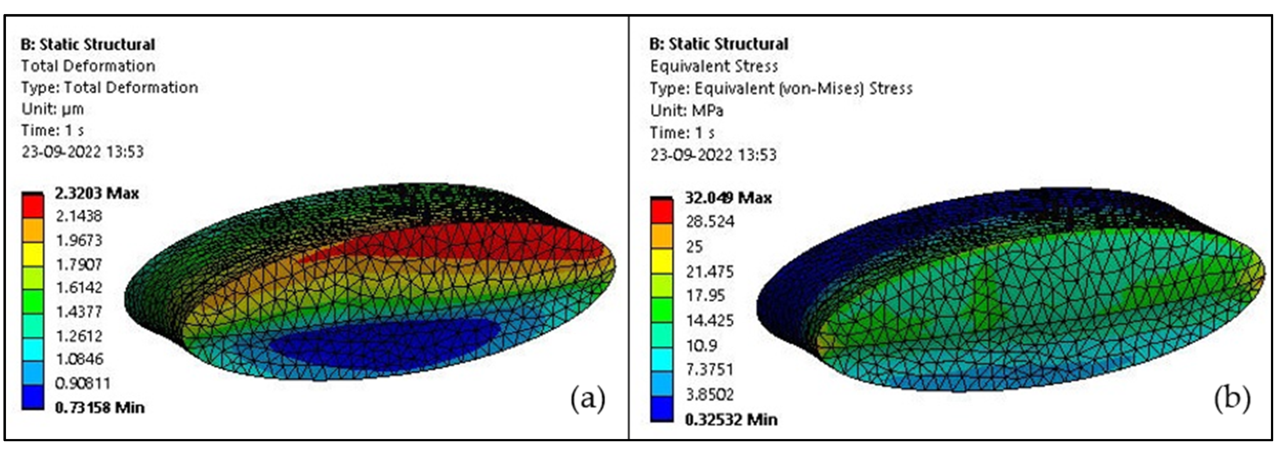
From the analysis, it is observed that at a temperature of 55 °C and loading of 140 N, Group 5 shows the highest deformation and von Mises stress value, which are 2.793 μm and 54.206 MPa. It is also observed that Group 1 shows the least deformation and von Mises stress value, which are 2.320 μm and 32.049 MPa, as shown in Figure 13a,b. It is observed that the deformation occurred at the upper right end of the cavity.

3.9. Comparison of von Mises Stresses and Deformation in Trapezoidal Cavity Restoration

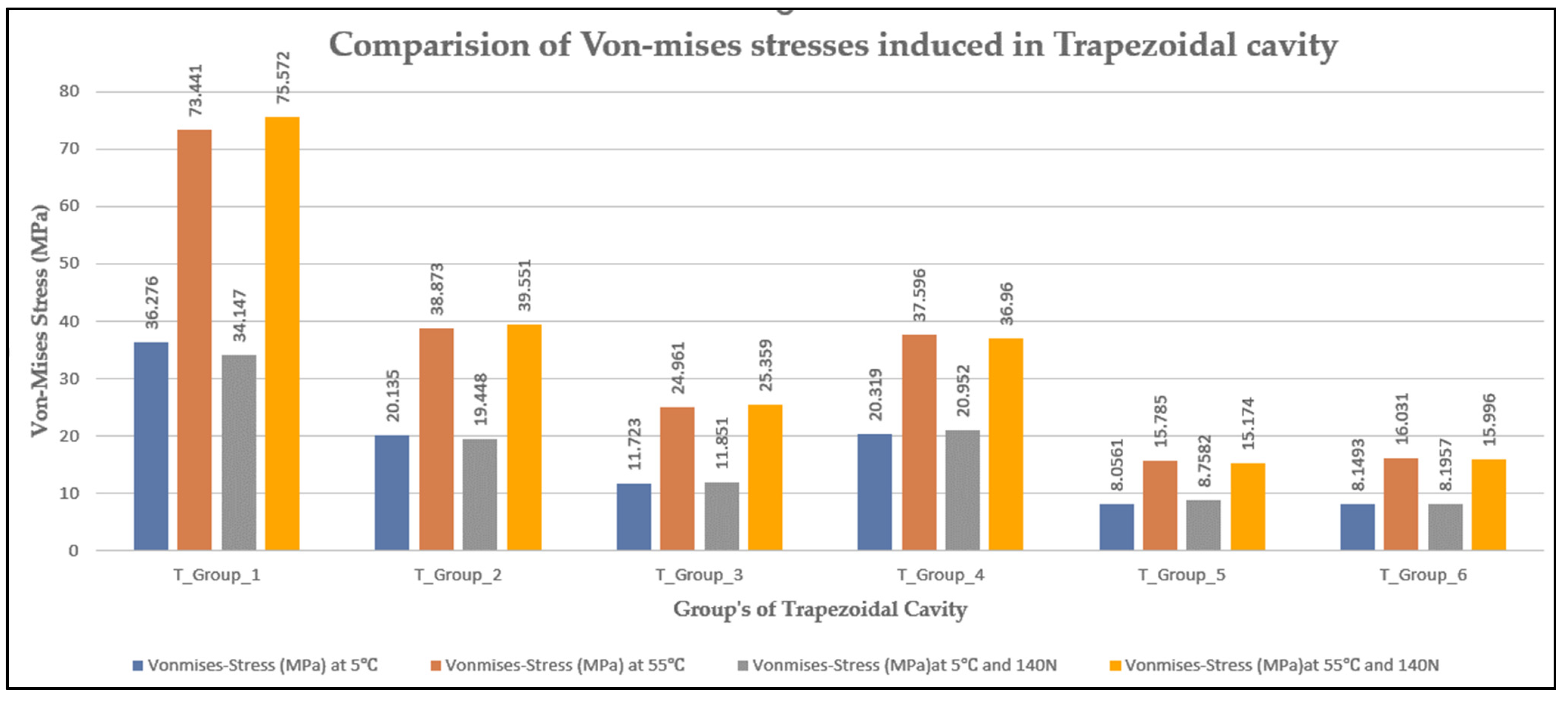
The von Mises stresses and deformation of trapezoidal cavity restorative materials at 5 °C and 55 °C under thermal and thermomechanical loading are shown in Figure 14 and Figure 15 respectively.

3.10. Comparison of von Mises Stresses and Deformation in Elliptical Cavity Restoration

The von Mises stresses and deformation of elliptical cavity restorative material are at 5 °C and 55 °C under thermal and thermomechanical loading are shown in Figure 16 and Figure 17 respectively.

4. Discussion

Due to the various physical and thermal characteristics of various restorative materials, a temperature gradient caused by hot and cold liquid drinks in the mouth leads to thermal stresses. The heat transfer among the materials occurs due to conduction. Thus, an increase or decrease in temperature results in thermal stresses. The thermal stresses could result in tension stress, which leads to crack initiation or growth within the restorative materials, thereby causing catastrophic failure. The study conducted by Swathi Pai et al. [1] has shown that a cervical trapezoidal cavity will undergo the least deformation and von Mises stress when Group 5 materials (1 mm GIC, 0.06 mm hybrid layer, 2 mm composite resin) are used, and it is also shown that a cervical elliptical-shaped cavity will undergo the least deformation and von Mises stress when Group 6 (2 mm GIC, 0.06 mm hybrid layer, 1 mm composite resin) materials are used. However, this study did not focus on thermal analysis. The chances of deformation would be higher because of high thermal stress due to temperature differences while drinking hot or cold beverages. In the present study, the main focus was on the behavior of the materials under different thermal and thermomechanical loading conditions.
Several studies have reported that thermal stress concentrations occur at biomaterial interfaces [16,17,18,19,20,21]. Therefore, it is very necessary to achieve good adhesion between the two layers to resist the applied load [21]. Clinically, this can be achieved by using good isolation techniques. Different stress levels may be caused by variations in the crown shape, boundary conditions, type, size, and several parts, as well as loading conditions. In our finite element analysis, we neglected the effect of the pulp chamber on the stress distribution and assumed that all materials were linearly elastic and isotropic, remaining elastic under applied thermal loads [22]. These results obtained in the study of Anusavice et al. [23] supported the outcomes of Gulec and Ulusoy [24], who argued that materials with low elastic moduli put additional stress on dental tissues. In their study, Gulec and Ulusoy [24] found that interbedded ceramic had the lowest stress value, and Vita Enamic had the greatest von Mises stress values.
From this study, it can be concluded that the stresses induced in the elliptical cavity are slightly lower than those in a trapezoidal cavity. The study conducted by Nabih et al. [25] has shown the mechanical and thermal stresses of Vita Enamic and IPS e.max CAD. Compared to Vita Enamic, the IPS e.max CAD produced more valuable stresses on the tooth structure. From the results obtained, it was observed that the materials that have higher elastic modulus will undergo the least deformation. The temperature variations significantly affect the stresses induced on both restoration and tooth structures. This study was not focused on thermomechanical loading, which is a crucial real-time condition where both thermal and mechanical loads interact. However, the present study focused on both thermal and thermomechanical conditions where a concentrated load of 140 N was applied on three occlusion points [19], along with a temperature of 5 °C and 55 °C applied to the dentin–enamel junction while maintaining cementum temperature at 35 °C. The least von Mises stress and deformation for the trapezoidal cavity were observed by Group 6 (2 mm GIC, 0.06 µm hybrid layer, 1 mm composite resin), and the least von Mises stress and deformation for the elliptical cavity were also observed by Group 1 (1 mm GIC, 0.03 µm hybrid layer, 2 mm composite resin). The least amount of deformation and von Mises stress was observed in two distinct groups, although identical materials were used for the restoration of the trapezoidal and elliptical cavities. In the current study, the deformation observed in both shapes is very negligible; therefore, it would not be significant to compare them entirely based on deformation. Analyzing the region of maximum stress, it is observed that the higher stress values are experienced at the interface between the hybrid layer and GIC. According to a study conducted by Nabih [25], the strains placed on both the restoration and the tooth structure are greatly influenced by thermal temperature variations, and IPS e.max CAD produced more favorable stresses on the tooth structure than Vita Enamic. The findings of Nabih [25] concurred with those of Yin et al. [26]. They claimed that the low fracture resistance and flexural strength of the polymer-infiltrated ceramic network compared to glass ceramics, which causes higher stresses on the restoration and surrounding structure at the applied magnitude of load and may be the cause of these results. In accordance with Lin et al. [27], Ausiello et al. [28], Rees et al. [29], Federlin et al. [30], and Ausiello et al. [12], the results of their investigation likewise demonstrated that tensile stresses were lower than compressive stresses.
Dejak and Mlotkowski [31] used a three-dimensional (3D) finite element analysis involving contact elements in the research. Seven identical 3-D replicas of primary molars were modelled. Intact tooth (IT), unrestored tooth (UT), tooth with a cavity prepared using the Modified Open Technique (MOT); tooth restored with composite resin inlays (CRIT) (True Vitality; 5.4 GPa elastic modulus); tooth restored with composite resin inlays (CRIH) (Herculite XRV; 9.5 GPa elastic modulus); tooth restored with composite resin inlays (CRIC) (Charisma; 14.5 GPa elastic modulus); tooth restored with composite resin inlays (CRIZ) (Z100) The occlusal surface of each model was subjected to 200 N of stress. Calculations were made to determine the stresses experienced by the inlays, composite resin cement layer, and tooth tissues during testing. The Mohr-Coulomb failure criterion was employed to assess material toughness. Dejak and Mlotkowski [31] measured the tensile and shear binding strengths of luting cement to enamel and dentin, and compared them to contact stresses in the cement-tissue adhesive interface. It was found that the Mohr-Coulomb failure criterion values were lower in teeth restored with composite resin and ceramic inlays compared to those of unrestored teeth with a preparation (UT), but were still 2.5 times higher than those of an undamaged tooth (IT). The Mohr-Coulomb failure criterion values were nearly three times higher for the ceramic inlay (CI) than for the composite resin inlays. These numbers were 2–4 times smaller for the ceramic inlay model’s luting agent compared to those of the composite resin inlay models’ luting agents. Contact tensile and shear stresses were lower at the adhesive interface between the cement and tooth surrounding the ceramic inlays than they were around the composite resin inlays. It was shown that stresses exceeded tissue strength in the cervical enamel adjacent to the inlays’ proximal surface.
Toparli et al. [8] found that composite resin shows better behavior than amalgam when cold liquid (15 °C) is used. On the contrary, amalgam is more satisfactory when hot liquid (60 °C) is used [6]. However, we found that the lowest von Mises stress was at the tooth–restorative interface at both 5 °C and 55 °C. The results of our study are not in agreement with those of Toparli et al. [8] This difference may be related to the different experimental conditions of MS Guler [32] study. MS Guler [32] observed that when thermal changes at the interface of tooth materials are taken into account, the smallest stress and maximum stress were found in amalgam and glass ionomer cement, respectively. The varying mechanical and thermal qualities of restorative materials could be the cause. As a result, amalgam could be employed in class V cavities to minimize stress on the restorative material and lower the chance of material loss. The results reported here need to be confirmed by more in vivo and in vitro research.
Temperature fluctuations in the mouth cause cyclic changes that may cause the thermal fatigue of the adhesive process [32,33]. The tensile stresses were produced at the regions of load application on the occlusal surface in both restored cases. Therefore, it is essential to control this surface roughness by polishing it to avoid stress concentration spots and the development of fatigue cracks, which might lead to fracture [34,35,36,37,38].
The present study revealed that the stress induced in the trapezoidal cavity is slightly higher than in the elliptical cavity. For example, Group 1 of elliptical-shaped cavities generated von Mises stresses of about 14.65 MPa (at 5 °C), 41.84 MPa (at 55 °C), 14.83 MPa (at 5 °C and 140 N), and 28.89 MPa (55 °C and 140 N), while the trapezoidal cavity generated 36.27 MPa (at 5 °C), 74.44 MPa (at 55 °C), 34.14 MPa (at 5 °C and 140 N), and 75.57 MPa (55 °C and 140 N), which is significantly higher than the stress in elliptical cavities. This could be the result of sharp edges present in a trapezoidal cavity as stress concentration occurs because of the sudden change in the geometry. Further study on fatigue analysis is required to predict the number of cycles to the failure. This analysis can be applied to all kinds of cavity restorations to predict the life of the filler material.

5. Conclusions

The least deformation and von Mises stress for an elliptical-shaped cavity were shown by Group 1 (1 mm GIC, 0.03 µm adhesive layer, and 2 mm composite layer), and the highest was shown by Group 5 (1 mm GIC, 0.06 µm adhesive layer, and 2 mm composite layer), whereas, in the trapezoidal-shaped cavity, the highest deformation and stress were observed in Group 1 (1 mm GIC, 0.03 µm adhesive layer, and 2 mm composite layer), and the least stress in Group 6 (2 mm GIC, 0.06 µm adhesive layer, and 1 mm composite layer). It was observed that maximum deformation occurred at the upper right end of the cavity. From this study, we can conclude that the stresses induced in the elliptical cavity are slightly lower when compared to the trapezoidal cavity. The transfer of load between the layers is largely governed by the cavity shape.

Author Contributions

Conceptualization, R.S.U., S.P. (Swathi Pai) and N.N.; methodology, R.S.U., S.P. (Swathi Pai), V.P. and N.N.; software, R.S.U., P.G., A.J. and S.P. (Santosh Patil); validation, R.R. and S.P. (Santosh Patil); formal analysis, R.S.U., N.N. and S.P. (Santosh Patil); investigation, J.T.; resources, K.S., R.S., J.T. and R.R.; data curation, S.P. (Swathi Pai) and R.R.; writing—original draft preparation, R.S., P.G., A.J. and R.R.; writing—review and editing, S.P. (Swathi Pai), K.S., N.N. and P.H.; visualization, V.P., K.S. and P.G.; supervision, V.P., N.N. and P.H.; project administration, S.P. (Swathi Pai) and N.N. All authors have read and agreed to the published version of the manuscript.

Funding

This research has not received external funding.

Institutional Review Board Statement

This research was conducted with permission from the Institutional Ethics Committee (IEC No. 883–2018). All procedures performed in this study involving human participants were in accordance with the ethical standards of the institutional and/or national research committee and with the 1964 Helsinki declaration and its later amendments or comparable ethical standards.

Data Availability Statement

All data and material collected are presented in the manuscript. Requests for clarification on any matter can be made through the corresponding author.

Acknowledgments

The authors acknowledge the Department of Mechanical and Industrial Engineering, Manipal Institute of Technology, Manipal Academy of Higher Education, Manipal for providing technical support and computing facility for the analysis.

Conflicts of Interest

The authors declare no conflict of interest.

References

  1. Pai, S.; Nayak, N.; Awasthi, S.; Acharya, S.R.; Bhat, V.; Patil, V. Effect of thickness of various restorative materials and hybrid layer on stress distribution of direct cervical restorations of teeth using a three-dimensional structural finite element analysis. Eng. Sci. 2021, 16, 281–287. [Google Scholar] [CrossRef]
  2. Cakici, E.B.; Guler, M.S.; Guler, C.; Cakici, F.; Sen, S. Finite element analysis of thermal stress distribution in different restorative materials used in class V cavities. Niger. J. Clin. Pract. 2016, 19, 30. [Google Scholar] [CrossRef] [PubMed]
  3. Sen, D.; Patil, V.; Smriti, K.; Varchas, P.; Ratnakar, R.; Naik, N.; Kumar, S.; Saxena, J.; Kapoor, S. Nanotechnology and Nanomaterials in Dentistry: Present and Future Perspectives in Clinical Applications. Eng. Sci. 2022, 20, 14–24. [Google Scholar] [CrossRef]
  4. Babaei, B.; Shouha, P.; Birman, V.; Farrar, P.; Prentice, L.; Prusty, G. The effect of dental restoration geometry and material properties on biomechanical behaviour of a treated molar tooth: A 3D finite element analysis. J. Mech. Behav. Biomed. Mater. 2022, 125, 104892. [Google Scholar] [CrossRef] [PubMed]
  5. Kim, S.-Y.; Kim, B.-S.; Kim, H.; Cho, S.-Y. Occlusal Stress Distribution and remaining crack propagation of a cracked tooth treated with different materials and designs: 3D finite element analysis. Dent. Mater. 2021, 37, 731–740. [Google Scholar] [CrossRef] [PubMed]
  6. Browning, W.D.; Brackett, W.W.; Gilpatrick, R.O. Two-year clinical comparison of a microfilled and a hybrid resin-based composite in non-carious Class V lesions. Oper. Dent. 2000, 25, 46–50. [Google Scholar] [PubMed]
  7. Palmer, D.S.; Barco, M.T.; Billy, E.J. Temperature extremes produced orally by hot and cold liquids. J. Prosthet. Dent. 1992, 67, 325–327. [Google Scholar] [CrossRef]
  8. Toparli, M.; Gokay, N.; Aksoy, T. An investigation of temperature and stress distribution on a restored maxillary second premolar tooth using a three-dimensional finite element method. J. Oral Rehabil. 2000, 27, 1077–1081. [Google Scholar] [CrossRef]
  9. Jiang, W.; Bo, H.; YongChun, G.; LongXing, N. Stress distribution in molars restored with inlays or onlays with or without endodontic treatment: A three-dimensional finite element analysis. J. Prosthet. Dent. 2010, 103, 6–12. [Google Scholar] [CrossRef]
  10. Moeen, F.; Nisar, S.; Dar, N. A step by step guide to finite element analysis in dental implantology. Pak. Oral Dent J. 2014, 34, 164–169. [Google Scholar]
  11. Gateau, P.; Sabek, M.; Dailey, B. In vitro fatigue resistance of glass ionomer cements used in post-and-coreapplications. J. Prosthet. Dent. 2001, 86, 149–155. [Google Scholar] [CrossRef] [PubMed]
  12. Ausiello, P.; Franciosa, P.; Martorelli, M.; Watts, D.C. Numerical Fatigue 3D-FE modeling of indirect composite-restored posterior teeth. Dent. Mater. 2011, 27, 423–430. [Google Scholar] [CrossRef] [PubMed]
  13. Korioth, T.W.; Versluis, A. Modeling the mechanical behavior of the jaws and their related structures by finite element (FE) analysis. Crit. Rev. Oral Biol. Med. 1997, 8, 90–104. [Google Scholar] [CrossRef] [PubMed] [Green Version]
  14. Ye, Q.; Spencer, P. Analyses of material-tissue interfaces by Fourier transform infrared, Raman spectroscopy, and chemometrics. In Material-Tissue Interfacial Phenomena; Woodhead Publishing: Sawston, UK, 2017; pp. 231–251. [Google Scholar]
  15. Belli, S.; Eskitaşcio, G.; Eraslan, O.; Senawongse, P.; Tagami, J. Effect of hybrid layer on stress distribution in a premolar tooth restored with composite or ceramic inlay: An FEM study. J. Biomed. Mater. Res. Part B Appl. Biomater. 2005, 74, 665–668. [Google Scholar] [CrossRef] [PubMed]
  16. Valin Rivera, J.L.; Gonçalves, E.; Vinicius Soares, P.; Milito, G.; Ricardo Perez, J.O.; Palacios Roque, G.F.; Valin Fernández, M.; Figueredo Losada, H.; Araújo Pereira, F.; Garcia del Pino, G.; et al. The Restored Premolars Biomechanical Behavior: FEM and Experimental Moiré Analyses. Appl. Sci. 2022, 12, 6768. [Google Scholar] [CrossRef]
  17. Eliguzeloglu, E.; Eraslan, O.; Omurlu, H.; Eskitascıoglu, G.; Belli, S. Effect of hybrid layer and thickness on stress distribution of cervical wedge-shaped restorations. Eur. J. Dent. 2010, 4, 160–165. [Google Scholar] [CrossRef] [Green Version]
  18. Sundfeld, R.H.; Valentino, T.A.; de Alexandre, R.S.; Briso, A.L.F.; Sundefeld, M.L.M.M. Hybrid layer thickness and resin tag length of a self-etching adhesive bonded to sound dentin. J. Dent. 2005, 33, 675–681. [Google Scholar] [CrossRef]
  19. Sorrentino, R.; Aversa, R.; Ferro, V.; Auriemma, T.; Zarone, F.; Ferrari, M.; Apicella, A. Three-dimensional finite element analysis of strain and stress distributions in endodontically treated maxillary central incisors restored with different post, core and crown materials. Dent Mater. 2007, 23, 983–993. [Google Scholar] [CrossRef]
  20. Aykul, H.; Toparli, M.; Dalkiz, M. A calculation of stress distribution in metal-porcelain crowns by using three-dimensional finite element method. J. Oral Rehabil. 2002, 29, 381–386. [Google Scholar] [CrossRef]
  21. Yang, H.-S.; Lang, L.A.; Guckes, A.D.; Felton, D.A. The effect of thermal change on various dowel-and-core restorative materials. J. Prosthet. Dent. 2001, 86, 74–80. [Google Scholar] [CrossRef]
  22. Toparli, M.; Aykul, H.; Sasaki, S. Temperature and thermal stress analysis of a crowned maxillary second premolar tooth using three-dimensional finite element method. J. Oral Rehabil. 2002, 30, 99–105. [Google Scholar] [CrossRef] [PubMed]
  23. Anusavice, K.J.; Hojjatie, B. Influence of incisal length of ceramic and loading orientation on stress distribution in ceramic crowns. J. Dent. Res. 1988, 67, 1371–1375. [Google Scholar] [CrossRef] [PubMed]
  24. Gulec, L.; Ulusoy, N. Effect of endocrown restorations with different CAD/CAM materials: 3D finite element and Weibull analyses. BioMed Res. Int. 2017, 2017, 5638683. [Google Scholar] [CrossRef] [PubMed] [Green Version]
  25. Nabih, S.M.; Ibrahim, N.I.; Elmanakhly, A.R. Mechanical and thermal stress analysis of hybrid ceramic and lithium disilicate based ceramic CAD-cam inlays using 3-D Finite Element Analysis. Braz. Dent. Sci. 2021, 24, 1–10. [Google Scholar] [CrossRef]
  26. Yin, R.; Kim, Y.-K.; Jang, Y.-S.; Lee, J.-J.; Lee, M.-H.; Bae, T.-S. Comparative evaluation of the mechanical properties of CAD/CAM dental blocks. Odontology 2019, 107, 360–367. [Google Scholar] [CrossRef]
  27. Lin, C.-L.; Chang, C.-H.; Ko, C.-C. Multifactorial analysis of a mod restored human premolar using auto-mesh finite element approach. J. Oral Rehabil. 2001, 28, 576–585. [Google Scholar] [CrossRef]
  28. Ausiello, P.; Apicella, A.; Davidson, C.L. Effect of adhesive layer properties on stress distribution in composite restorations—A 3D finite element analysis. Dent. Mater. 2002, 18, 295–303. [Google Scholar] [CrossRef]
  29. Rees, J.S.; Hammadeh, M.; Jagger, D.C. Abfraction lesion formation in maxillary incisors, canines and premolars: A finite element study. Eur. J. Oral Sci. 2003, 111, 149–154. [Google Scholar] [CrossRef]
  30. Federlin, M.; Krifka, S.; Herpich, M.; Hiller, K.-A.; Schmalz, G. Partial ceramic crowns: Influence of ceramic thickness, preparation design and luting material on fracture resistance and marginal integrity in vitro. Oper. Dent. 2007, 32, 251–260. [Google Scholar] [CrossRef]
  31. Dejak, B.; Mlotkowski, A. Three-dimensional finite element analysis of strength and adhesion of composite resin versus ceramic inlays in molars. J. Prosthet. Dent. 2008, 99, 131–140. [Google Scholar] [CrossRef]
  32. Güler, M.S. Evaluation of stress distribution of different restorative materials in class V cavities. Atatürk Üniversitesi Diş Hekim. Fakültesi Derg. 2019, 28, 518–523. [Google Scholar] [CrossRef]
  33. Kotousov, A.; Kahler, B.; Swain, M. Analysis of interfacial fracture in dental restorations. Dent. Mater. 2011, 27, 1094–1101. [Google Scholar] [CrossRef]
  34. Bai, K.; Zhang, T.H.; Yang, Z.Y.; Song, F.; Yang, X.D.; Wang, K. Anisotropic, gradient and metal-like mechanical behaviors of teeth and their implications on tooth functions. Chin. Sci. Bull. 2007, 52, 2310–2315. [Google Scholar] [CrossRef] [Green Version]
  35. Singh, V.; Misra, A.; Marangos, O.; Park, J.; Ye, Q.; Kieweg, S.L.; Spencer, P. Fatigue life prediction of dentin–adhesive interface using micromechanical stress analysis. Dent. Mater. 2011, 27, e187–e195. [Google Scholar] [CrossRef] [PubMed] [Green Version]
  36. Yahyazadehfar, M.; Ivancik, J.; Majd, H.; An, B.; Zhang, D.; Arola, D. On the mechanics of fatigue and fracture in teeth. Appl. Mech. Rev. 2014, 66, 030803. [Google Scholar] [CrossRef] [PubMed]
  37. Sharma, D.; Kudva, V.; Patil, V.; Kudva, A.; Bhat, R.S. A Convolutional Neural Network Based Deep Learning Algorithm for Identification of Oral Precancerous and Cancerous Lesion and Differentiation from Normal Mucosa: A Retrospective Study. Eng. Sci. 2022, 18, 278–287. [Google Scholar] [CrossRef]
  38. Prabhu, N.; Shetty, D.K.; Naik, N.; Shetty, N.; Kalpesh Parmar, Y.; Patil, V.; Sooriyaperakasam, N. Application of finite element analysis to evaluate optimal parameters for bone/tooth drilling to avoid thermal necrosis. Cogent Eng. 2021, 8, 1876582. [Google Scholar] [CrossRef]
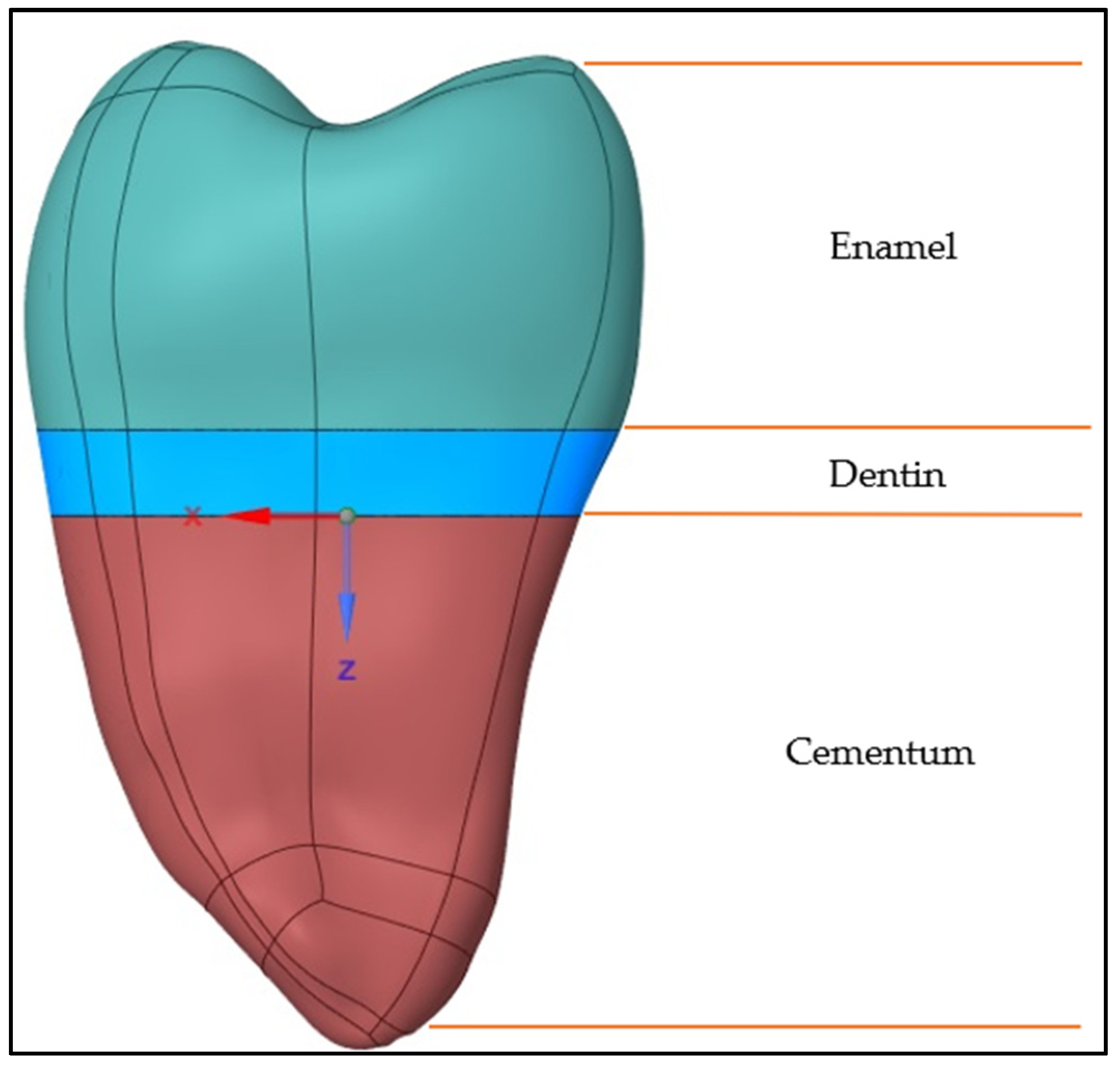
Figure 1. Premolar tooth model.
Jcs 07 00006 g001
Figure 2. (a) Trapezoidal cavity; (b) elliptical cavity.
Jcs 07 00006 g002
Figure 3. (a) Restorative materials for elliptical cavity; (b) restorative materials for trapezoidal cavity.
Jcs 07 00006 g003
Figure 4. Mesh convergence test for system response for a converged repeatable solution.
Jcs 07 00006 g004
Figure 5. (a) Meshed models of a trapezoidal-shaped cavity; (b) meshed models of an elliptical-shaped cavity.
Jcs 07 00006 g005
Figure 6. (a) Deformation observed in Group 6 at a temperature of 5 °C; (b) von Mises stress induced in Group 6 at a temperature of 5 °C.
Jcs 07 00006 g006
Figure 7. (a) Deformation observed in Group 6 at a temperature of 55 °C; (b) von Mises stress induced in Group 6 at a temperature of 55 °C.
Jcs 07 00006 g007
Figure 8. (a) Deformation observed in Group 6 at a temperature of 5 °C and loading of 140 N; (b) von Mises stress induced in Group 6 at a temperature of 5 °C and loading of 140 N.
Jcs 07 00006 g008
Figure 9. (a) Deformation observed in Group 6 at a temperature of 55 °C and loading of 140 N; (b) von Mises stress induced in Group 6 at a temperature of 55 °C and loading of 140 N.
Jcs 07 00006 g009
Figure 10. (a) Deformation observed in Group 1 at a temperature of 5 °C; (b) von Mises stress induced in Group 1 at a temperature of 5 °C.
Jcs 07 00006 g010
Figure 11. (a) Deformation observed in Group 1 at a temperature of 55 °C; (b) von Mises stress induced in Group 1 at a temperature of 55 °C.
Jcs 07 00006 g011
Figure 12. (a) Deformation observed in Group 1 at a temperature of 5 °C and loading of 140 N; (b) von Mises stress induced in Group 1 at a temperature of 5 °C and loading of 140 N.
Jcs 07 00006 g012
Figure 13. (a) Deformation observed in Group 1 at a temperature of 55 °C and loading of 140 N; (b) von Mises stress induced in Group 1 at a temperature of 55 °C and loading of 140 N.
Jcs 07 00006 g013
Figure 14. von Mises stresses under thermal and thermomechanical analysis for a trapezoidal cavity.
Jcs 07 00006 g014
Figure 15. Deformation observed under thermal and thermomechanical analysis for a trapezoidal cavity.
Jcs 07 00006 g015
Figure 16. von Mises stresses under thermal and thermomechanical analysis for an elliptical cavity.
Jcs 07 00006 g016
Figure 17. Deformation observed under thermal and thermomechanical analysis for an elliptical cavity.
Jcs 07 00006 g017
Table 1. Properties of the materials used in the study.
MaterialsYoung’s Modulus of Elasticity (GPa)Poisson’s RatioThermal Expansion Coefficient (1/°C)Thermal Conductivity (W/m °C)
Enamel800.3311 × 10−60.84
Dentin200.3111.4 × 10−60.63
Cementum13.70.310 × 10−65.8
Hybrid Layer7.70.339 × 10−62.61
Composite Resin150.2434 × 10−61.26
Glass Ionomer Cement10.80.335 × 10−60.615
Table 2. Division of groups according to the thickness of restorative materials.
GroupsThe Thickness of Layers of Restorative Materials
Glass Ionomer Cement (mm)Hybrid Layer (mm)Composite Resin (mm)
Group 110.032
Group 220.031
Group 31.50.031.5
Group 41.50.061.5
Group 510.062
Group 620.061
Table 3. Mesh convergence test.
Elementsvon Mises Stress
(MPa)
Deformation
(mm)
% ChangeOuter Body Element Size
(mm)
Restorative Material Element Size
(mm)
Temperature
(°C)
Load (N)
242,11877.6210.005−2.6670.40.255140
138,53077.8640.005−1.0400.50.255140
92,59478.2250.005−0.5810.60.255140
69,60778.6820.0051200.70.255140
56,32579.7480.0061.3550.80.255140
48,53381.0260.0072.9790.90.255140
43,34783.6760.0096.34710.255140
Table 4. Thermal analysis results at a temperature of 5 °C.
ShapeThermal Loading
5 °C
TrapezoidalDeformation (μm)von Mises Stress (MPa)
Group 12.36936.276
Group 21.07720.135
Group 30.89911.723
Group 40.87920.319
Group 50.8698.758
Group 60.8748.149
Table 5. Thermal analysis results at a temperature of 55 °C.
ShapeThermal Loading
55 °C
TrapezoidalDeformation (μm)von Mises Stress (MPa)
Group 15.20973.441
Group 22.79738.873
Group 32.52624.961
Group 42.46637.596
Group 52.36816.031
Group 62.36415.785
Table 6. Thermomechanical analysis results at a temperature of 5 °C and loading of 140 N.
ShapeThermomechanical Loading
5 °C and 140 N
TrapezoidalDeformation (μm)von Mises Stress (MPa)
Group 12.47134.147
Group 21.16619.448
Group 30.98811.851
Group 40.09720.952
Group 50.9788.758
Group 60.9678.196
Table 7. Thermomechanical analysis results at a temperature of 55 °C and loading of 140 N.
ShapeThermomechanical Loading
55 °C and 140 N
TrapezoidalDeformation (μm)von Mises Stress (MPa)
Group 15.12375.572
Group 22.6939.551
Group 32.42925.359
Group 42.36736.96
Group 52.29315.996
Group 62.19115.174
Table 8. Thermal analysis results at a temperature of 5 °C.
ShapeThermal Loading
5 °C
EllipticalDeformation (μm)von Mises Stress (MPa)
Group 10.96914.657
Group 21.27818.418
Group 31.35718.207
Group 41.35117.999
Group 51.47727.899
Group 61.26816.655
Table 9. Thermal analysis results at a temperature of 55 °C.
ShapeThermal Loading
55 °C
EllipticalDeformation (μm)von Mises Stress (MPa)
Group 12.46232.331
Group 22.48235.753
Group 32.63635.343
Group 42.62234.94
Group 52.86954.156
Group 62.71441.283
Table 10. Thermomechanical analysis results at a temperature of 5 °C and loading of 140 N.
ShapeThermomechanical Loading
5 °C and 140 N
EllipticalDeformation (μm)von Mises Stress (MPa)
Group 11.06914.537
Group 21.45318.876
Group 31.45318.497
Group 41.52718.719
Group 51.58228.886
Group 61.44517.23
Table 11. Thermomechanical analysis results at a temperature of 55 °C and loading of 140 N.
ShapeThermomechanical Loading
55 °C and 140 N
EllipticalDeformation (μm)von Mises Stress (MPa)
Group 12.32032.049
Group 22.33935.479
Group 32.55535.068
Group 42.47734.236
Group 52.79354.206
Group 62.63637.049
Disclaimer/Publisher’s Note: The statements, opinions and data contained in all publications are solely those of the individual author(s) and contributor(s) and not of MDPI and/or the editor(s). MDPI and/or the editor(s) disclaim responsibility for any injury to people or property resulting from any ideas, methods, instructions or products referred to in the content.