Article

Bond Strength and Corrosion Protection Properties of Hot-Dip Galvanized Prestressing Reinforcement in Normal-Strength Concrete

1
Klokner Institute, Czech Technical University in Prague, 166 08 Prague, Czech Republic
2
Faculty of Architecture, Czech Technical University in Prague, 166 34 Prague, Czech Republic
*
Author to whom correspondence should be addressed.
J. Compos. Sci. 2024, 8(10), 407; https://doi.org/10.3390/jcs8100407
Submission received: 13 August 2024 / Revised: 22 September 2024 / Accepted: 26 September 2024 / Published: 4 October 2024
(This article belongs to the Section Composites Manufacturing and Processing)

Abstract

:
Several prestressing reinforced structures have recently collapsed due to chloride-induced steel corrosion. This study investigates the effect of the corrosion of hot-dip galvanized conventional prestressing steel reinforcement under hydrogen evolution on bond strength in normal-strength concrete. The impact of hydrogen evolution on the porosity of cement paste at the interfacial transition zone (ITZ) is verified through image analysis. The whole surface of prestressing strands is hot-dip galvanized, and their corrosion behavior when embedded in the cement paste is investigated by measuring the time dependence of the open-circuit potential. Concerning the uniformity of the hot-dip galvanized coating and its composition, it is advisable to coat the individual wires of the prestressing reinforcement and subsequently form a strand. It is demonstrated that the corrosion of the coating under the evolution of hydrogen in the cement paste reduces the bond strength of hot-dip galvanized reinforcement in normal-strength concrete. Image analysis after 28 days of cement paste aging indicates insignificant filling of hydrogen-generated pores by zinc corrosion products. Applying an additional surface treatment (topcoat) stable in an alkaline environment is necessary to avoid corrosion of the coating under hydrogen evolution and limit the risk of bond strength reduction.

1. Introduction

Corrosion protection of conventional steel concrete reinforcement with a hot-dip galvanized (HDG) coating can extend the service life of reinforced concrete structures. This coating increases the corrosion resistance to carbonation of the concrete cover and the action of chloride anions [1,2,3]. However, it is also known that in fresh concrete, the hot-dip galvanized coating corrodes not only by the formation of Zn2+ cations (anodic corrosion reaction—see Equation (1)) but also by the development of hydrogen, which is formed by a cathodic corrosion reaction—see Equation (2) [4,5].
Z n Z n 2 + + 2 e
2 H 2 O + 2 e H 2 + 2 O H
The generated hydrogen can increase the porosity of the cement paste at the interfacial transition zone (ITZ), thereby reducing the bond strength of the coated reinforcement in the concrete [6,7,8]. However, according to the results of some studies, the evolution of hydrogen bubbles and the formation of specific corrosion products (calcium hydoxyzincate dihydrate—CHZ) has an insignificant effect on bond strength [9,10], it is usually recommended to apply an additional protective coating on the surface of hot-dip galvanized concrete reinforcement [11]. This topcoating aims to prevent the corrosion of hot-dip galvanized steel in fresh concrete under hydrogen evolution. For this purpose, conversion coatings [12,13], organofunctional silane-based coatings [14], or, e.g., acrylate dispersions [15] can be used. The hot-dip galvanized coating is currently also considered as corrosion protection for conventional prestressing reinforcement steel of concrete [16], and a suitable method of corrosion protection needs to be developed.
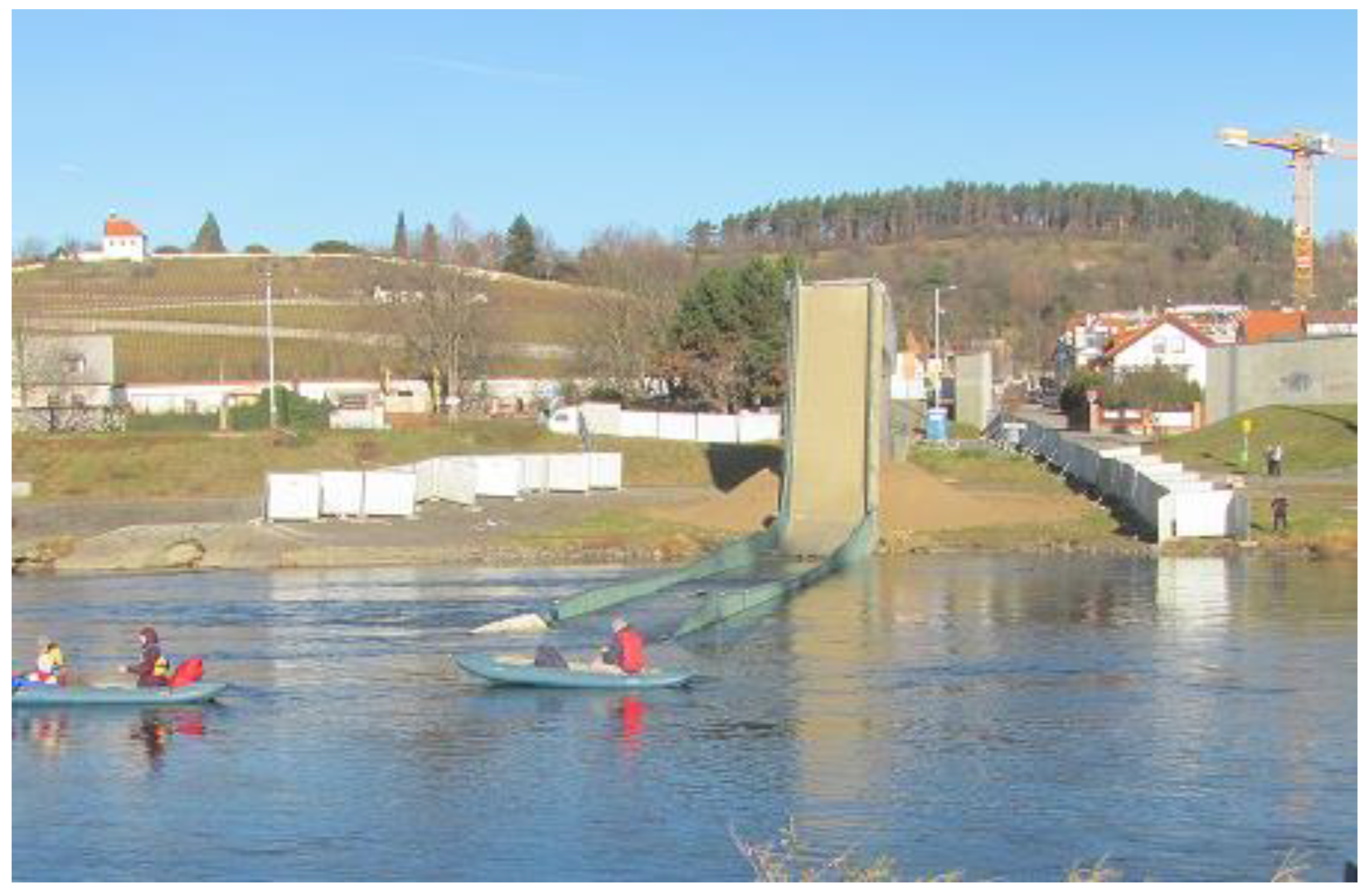
Usually, the corrosion damage of prestressing reinforcement is influenced by the stimulating effect of chloride anions—see Figure 1. The critical level of contamination of the grout itself (0.2 wt. % converted to cement content) in the prestressing reinforcement protector by chloride anions is lower than that of conventional reinforced concrete structures (0.4 wt. % converted to cement content) [17,18]. The electrochemical corrosion damage of the prestressing reinforcement stimulated by chloride anions likely contributed to the collapse of the cable-supported Prague-Troja footbridge in 2017 (stress ribbon, Figure 2) [19] and also of Ponte Morandi in Genoa in 2018 [20].
Previous studies investigated using epoxy coatings as corrosion protection for prestressing reinforcement in concrete. Adding hard additive particles to the top epoxy layer significantly increased the surface roughness of the reinforcement, and thus increased the bond strength in concrete [21]. A 2020 patent recommended protecting the surface of the conventional prestressing reinforcement with a hot-dip galvanized coating (batch technology) [16]. However, the recommendation to additionally coat the outer surface of the hot-dip galvanized coating to avoid hydrogen-induced bond strength reduction needs to be questioned as sound experimental evidence about the bond strength of such coated prestressing reinforcement in normal-strength concrete (NSC) is missing.
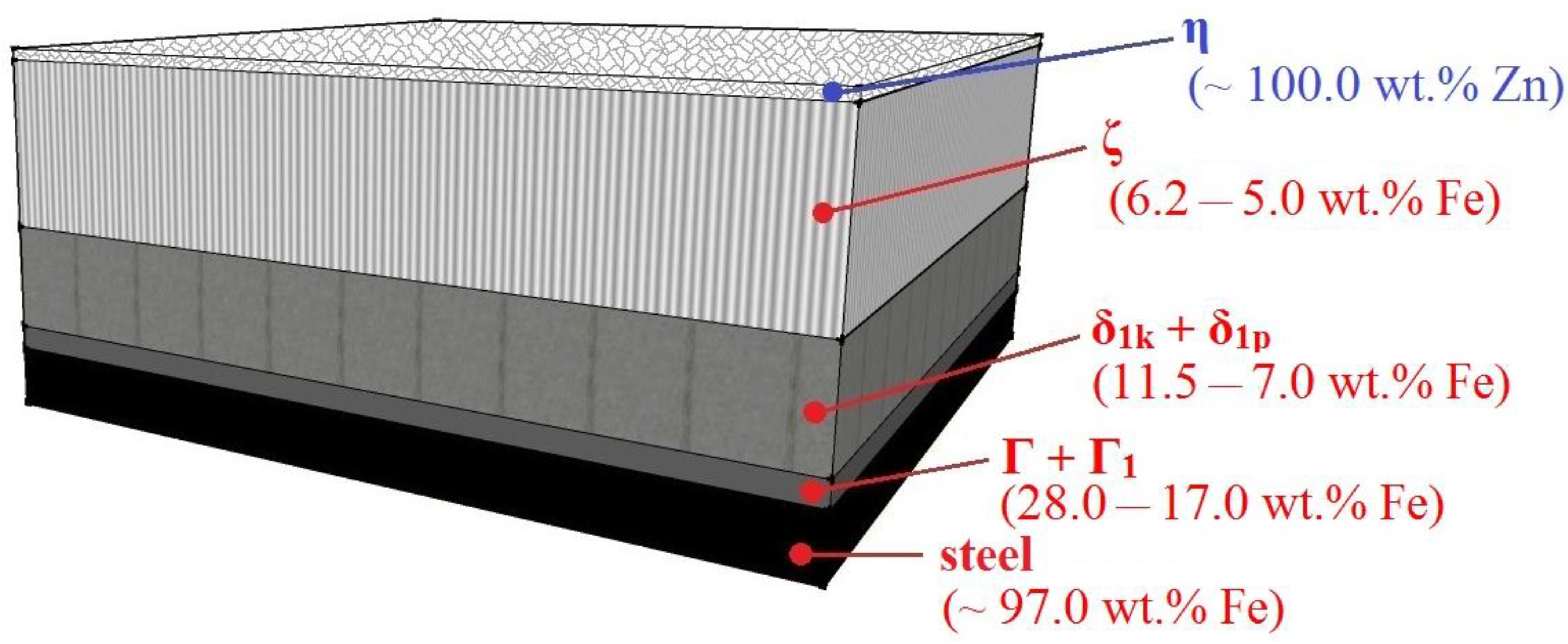
However, it is clear that the geometry of the reinforcement surface and the composition of the hot-dip galvanized coating have a significant effect on the bond strength of concrete. It has been discussed in the literature that the composition of the hot-dip galvanized coating has a major influence on corrosion behavior in concrete environments [22,23,24]. It is recommended that the external layer should be composed of phase η (a solid solution of iron in zinc with an iron content of about 0.03 wt. %) to ensure the conditions for the transition of corrosion from the active to the passive state as sufficient zinc is necessary for the formation of a continuous layer of Ca[Zn(OH)3]2·2H2O, the so-called CHZ—calcium hydroxyzincate dihydrate [22,23]. The hot-dip galvanized coating contains an inner layer of Fe-Zn intermetallic phases (see the composition of the HDG coating shown in Figure 3) under certain conditions (higher Si and P content in steel with a type of heat treatment playing a significant role), a coating can be formed when the outer layer is formed by the intermetallic phase ζ (FeZn13; the iron content is 5.00–6.02 wt. %) [25,26,27,28,29]. It has been experimentally shown that this phase exhibits lower corrosion resistance in the alkaline environment of concrete (higher corrosion rate, higher kinetics of H2 formation, formation of cracks across the coating) [30,31,32]. Thus, it is evident that the presence of an external layer of this phase can have a negative effect on the bond strength of the hot-dip galvanized steel in the concrete and on the extension of the service life of the structure since the Fe-Zn intermetallic phases exhibit lower resistance against chloride-induced corrosion.
This paper focuses on verifying the effect of hot-dip galvanized coating (batch technology) on the surface of currently used prestressing reinforcement (without applied prestressing) on corrosion behavior and bond strength under real conditions of the cement paste or normal strength concrete applications. In the case of corrosion, hydrogen-induced changes in the porosity of the cement paste at the interfacial transition zone (ITZ) are also tested.
This experimental verification aims to provide fundamental insights for the design of new and assessment of existing prestressed reinforced concrete structures with such coating (particularly for bridges in chloride-laden environments such as coastal areas or where de-icing salts are applied) concerning their service life (consideration of the effect of chloride anions) and possible changes in load capacity (effect of coating corrosion in fresh concrete on bond strength).

2. Materials and Methods

An experimental program was conducted to assess the corrosion properties and bond strength to concrete of hot-dip galvanized prestressing steel. The program included time-dependent measurements of the open-circuit potential (Ecorr) in real cement paste conditions (individual wires were tested) and bond strength testing using pull-out tests (cubic specimens of normal-strength concrete). Scanning electron microscopy was also used to evaluate the microstructure of the hot-dip galvanized coating on the prestressing steel and the influence of coating corrosion under hydrogen evolution on the porosity of the cement paste at the interfacial transition zone (ITZ).

2.1. Materials Used

For the aforementioned experimental research, a high-carbon steel strand (conventional prestressing steel reinforcement according to prEN 10138-3 [33]) type Y1860 (1.1366) S7 15.7 (supplier: Freyssinet CS, a.s., Zápy-Brandýs nd Labem-Stará Boleslav, Czech Republic) was used. The composition of steel Y1860 S7 15.7 is presented in Table 1 and the material characterization of the prestressing reinforcement steel is summarized in Table 2.
Samples of wires and strands of prestressing reinforcement were hot-dip galvanized in a commercial galvanizing plant (Apollo Metal, s.r.o., Čenkov, Czech Republic). Before coating, the samples were degreased at the Klokner Institute laboratory (CTU-Klokner Institute, Prague, Czech Republic) using mechanical cleaning with a CaO paste followed by conventional degreasing in 25 wt. % KOH for 20 min at 75 °C after rinsing in distilled water. The supplier of the surface treatment declared that the samples were also alkali-cleaned and pickled before the coating application [34]. Reference samples of wires (uncoated) were also degreased at the Klokner Institute laboratory before measuring the open-circuit potential. Reference samples of prestressing steel strands for bond strength testing were not degreased.
Portland cement CEM I 42.5 R (Českomoravský cement, a.s., Mokrá-Horákov, Czech Republic) was used for the preparation of the cement paste and concrete specimens, with its composition detailed in Table 3. For measuring the time-dependent Ecorr of individual prestressing steel wires, a cement paste with a water-to-cement ratio (w/c) of 0.35 was used, prepared according to the mix design given in Table 4. For bond strength tests, cubic concrete specimens with a w/c ratio of 0.55 were produced using normal-strength concrete (NSC) as per the mix design presented in Table 5 [35].

2.2. Corrosion Investigations

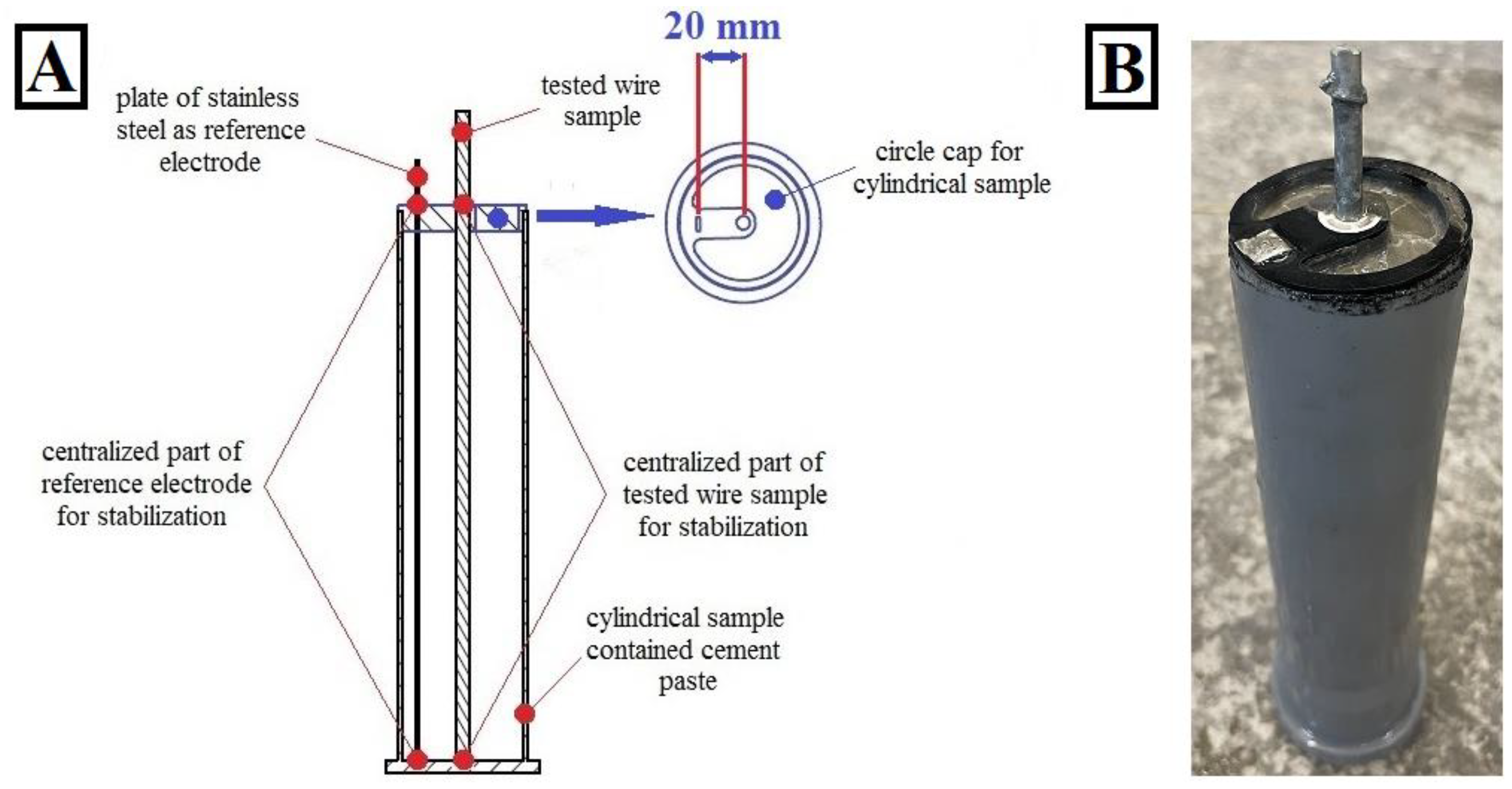
A total of 14 cylindrical concrete specimens were created to measure the time-dependent Ecorr (see Figure 4). These specimens contained prestressing steel wires as samples (7 uncoated wires and 7 hot dip galvanized wires). A cylindrical PE mold with a diameter of 50 mm and two centered PE caps were used. The mold and caps were 3D-printed (Prusa i3MK3S+ Prusa Research, Prague, Czech Republic). The total height of the mold was 150 mm. The bottom cap had no holes, and the gap between the cylindrical wall and the bottom cap was sealed with neutral elastic silicone-based sealant. The top cap had holes for inserting the prestressing steel wire specimen (uncoated or hot-dip galvanized). A hole was created at the top cap’s edge to place a reference electrode (foil) made of corrosion-resistant steel—FeCr18Ni9 (Goodfellow Metals, Huntingdon, UK). The distance between the reference electrode and the sample surface was 20 mm (see Figure 4) [6].
The cement paste was prepared with a higher water-to-cement ratio (w/c: 0.42) to ensure complete wetting of both the test wires and reference electrodes. To avoid potential interference with the corrosion process, plasticizers and aggregates were intentionally omitted. Therefore, the consistency of the cement paste could only be adjusted by adding water.
The evolution of the open-circuit potential (Ecorr) between the reference stainless steel and the prestressing steel wire specimen was measured using an OWON B35T+ multimeter (OWON-Fujian Lilliput Optoelectronics Technology Co., Ltd., Zhangzhou, China). Measurements were taken on the first day of exposure after 30 min and subsequently every 2 h for 6 days (the molds were stored in a humid atmosphere above the water level: 65% RH; 20.5 ± 1 °C). After this period, the specimens were submerged in water for 7 days (after approximately 170 h). Subsequently, the Ecorr of the samples was measured again (every 2 h), but the samples were removed from the water during measurements (and then returned to the water). Simultaneously, the potential difference between the reference electrode in the cement paste and a commercial saturated calomel electrode (SCE) was measured. Measurements were taken manually using an OWON B35T+ multimeter after opening the top cap of the mold (the average potential difference after 30 min of stabilization was determined to be −40 mV).

2.3. Bond Strength Investigation

To prepare the cubic normal-strength concrete (NSC) specimens, aggregates that absorbed a portion of the water were used [36]. Consequently, even though no plasticizer was added to the concrete mix, additional water was not required to ensure adequate wetting of the prestressing steel strand surface (actual w/c ratio: 0.55). The cement paste in the cylindrical specimens was manually compacted in four layers using a standard device (concrete mixer GIFOS MB 80; speed rotation: 30 rounds per minute) followed by vibration on a vibration table (GIFOS s.r.o., Brno-Horní Heršpice, Czech Republic). The NSC specimens in steel cubic molds were compacted using a hand-held device (Eibenstock EBR 125.1, 10,000 rpm-Elektrowerkzeuge GmbH Eibenstock, Eibenstock, Germany) for 1 min (the mold was filled in two separate layers and compacted). The prestressing steel strand specimen was anchored in the center of the steel cubic mold (for pull-out tests) using a wooden wedge (placed at the bottom of the mold) and a PE insert at the top (created by 3D printing)—see Figure 5.
All test specimens (cement paste, NSC) were cured in a humid atmosphere (95% RH; 20.5 ± 1 °C) for 28 days [37]. A total of 7 parallel specimens were prepared for bond tests.
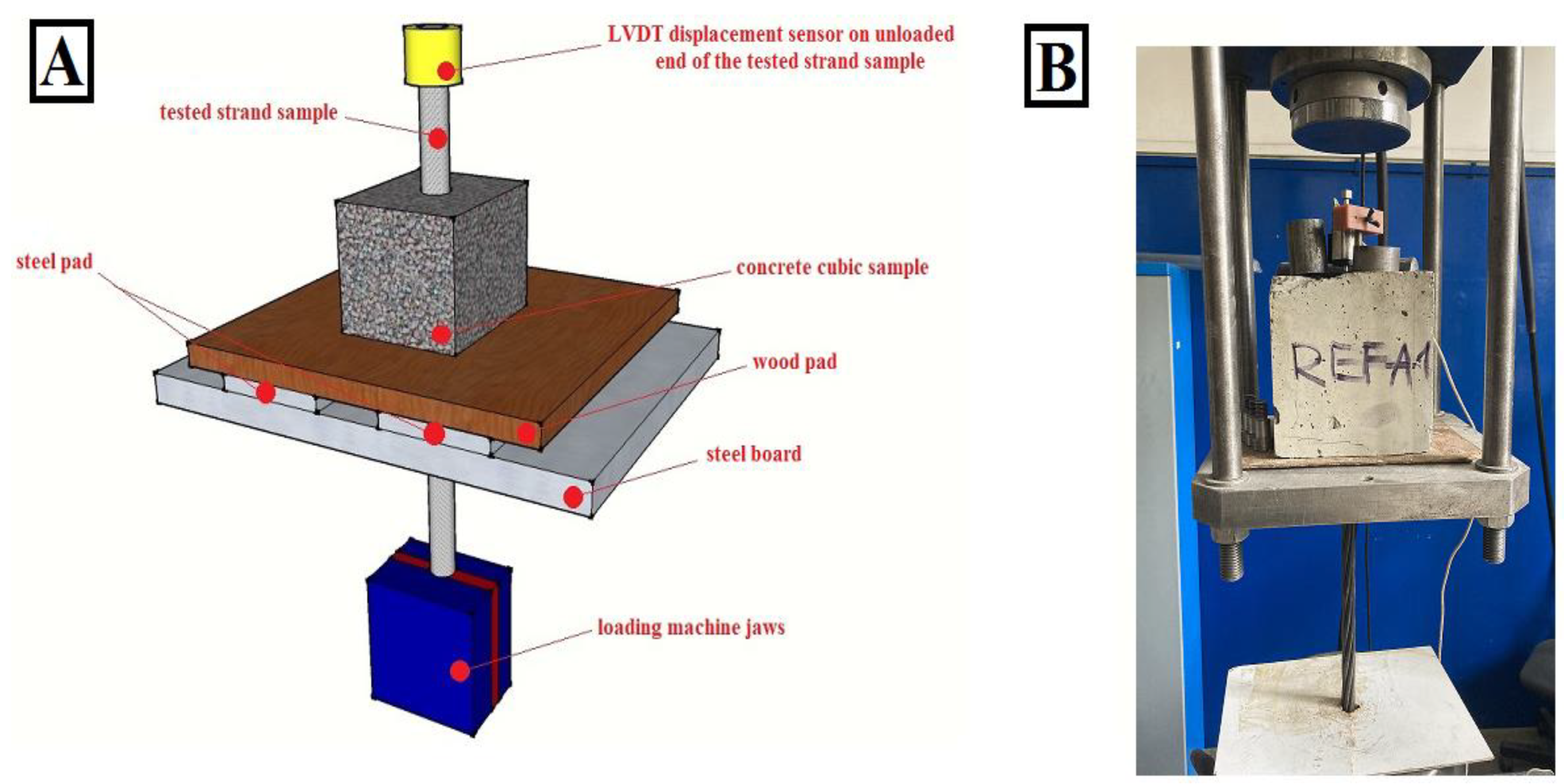
The pull-out tests to determine bond strength were conducted on cubic specimens according to RILEM RC6 [38] and ASTM C234-91a [39] standards. Bond strength was determined based on the slip–bond stress relationship. The slip was measured using an LVDT sensor (Micro-Epsilon Messtechnik GmbH, Ortenburg, Germany) placed on the unloaded end of the reinforcement—see Figure 6. The pull-out tests were performed on an MTS 500 kN testing machine. The pull-out test was controlled by displacing the unloaded end of a reinforcing bar at a constant rate of 0.005 mm/s [40]. The test was terminated when a slip of 2.0 mm was reached.

2.4. Scanning Electron Microscopy

The coating microstructure was evaluated using scanning electron microscopy (SEM) (Jeol JSM-IT200, Tokyo, Japan) and optical microscopy (Weldinspect DIM-U) on cross-sections. Grinding was performed on an automatic grinder LaboPol-2 (Struers GmbH, Willich, Germany) using grinding papers (P60-P2400) and diamond polishing pastes.
Measurements of the changes in porosity of the cement paste at the interfacial transition zone (ITZ) between the prestressing reinforcement and the cement paste (with a composition similar to the samples for Ecorr measurements) were conducted [6,14]. Steel strands were embedded to approximately 3/4 of their cross-sectional depth into 3 prismatic PE molds for each type of prestressing steel reinforcement (see Figure 7). After 28 days of curing at 60% RH, the reinforcements were removed from the specimens. After drying the mechanically divided cement paste samples (8 h, 85 °C), the porosity of the cement paste at the ITZ was measured. The total surface area occupied by pores (%) was evaluated and compared between the two types of interfaces (cement paste from uncoated prestressing reinforcement and hot-dip galvanized reinforcement). A scanning electron microscope (SEM) (Jeol JSM-IT200, Tokyo, Japan) and the free software ImageJ were used for evaluation. The total analyzed area from both samples was approximately 4 cm2.

2.5. Roughness Investigations of Prestressing Reinforcement

The surface roughness Ra (measured in the longitudinal direction) was verified for individual wire specimens (uncoated steel and hot-dip galvanized steel) from the prestressing steel reinforcement. The surface roughness has an effect on the bond strength of reinforcement in concrete. A total of 8 wires were measured (6 measurements per wire). The mean value and standard deviation of each reinforcement were evaluated. The individual wires were clamped separately in a clamping vice, and the measurements were performed using a MITUTOYO SJ-210 instrument (Mitutoyo, Kawasaki, Japan).

2.6. X-ray Diffraction of Corrosion Products

An X-ray diffraction analysis of the composition of the corrosion products was performed on a sample of hot-dip galvanized prestressing steel reinforcement exposed in cement paste (28 days of aging, reinforcement taken from an experiment to verify the changes in the porosity of cement paste on ITZ). For the actual analysis, a PAN analytical X´Pert3 instrument (Malvern Panalytical V. B., Almelo, The Netherlands) using CuKα radiation over the angular range 5–110° was used.

3. Results and Discussion

The results of the presented test program are discussed in four subsections. In Section 3.1, the composition of the hot-dip galvanized (HDG) coating on the individual wires of prestressing steel strain (six outer and one inner wire in total) is evaluated by scanning electron microscopy (SEM) [41]. In Section 3.2, the open-circuit potential of uncoated and HDG wires separated from the strands is measured in the cement paste. In Section 3.3, the results of pull-out tests of the bond strength of the prestressing steel strand in normal strength concrete are presented. In that section, the porosity of the cement paste taken from the ITZ zone (from the surface of both uncoated and HDG prestressing strands) is evaluated by image analysis (ImageJ).

3.1. Structure of HDG Coating

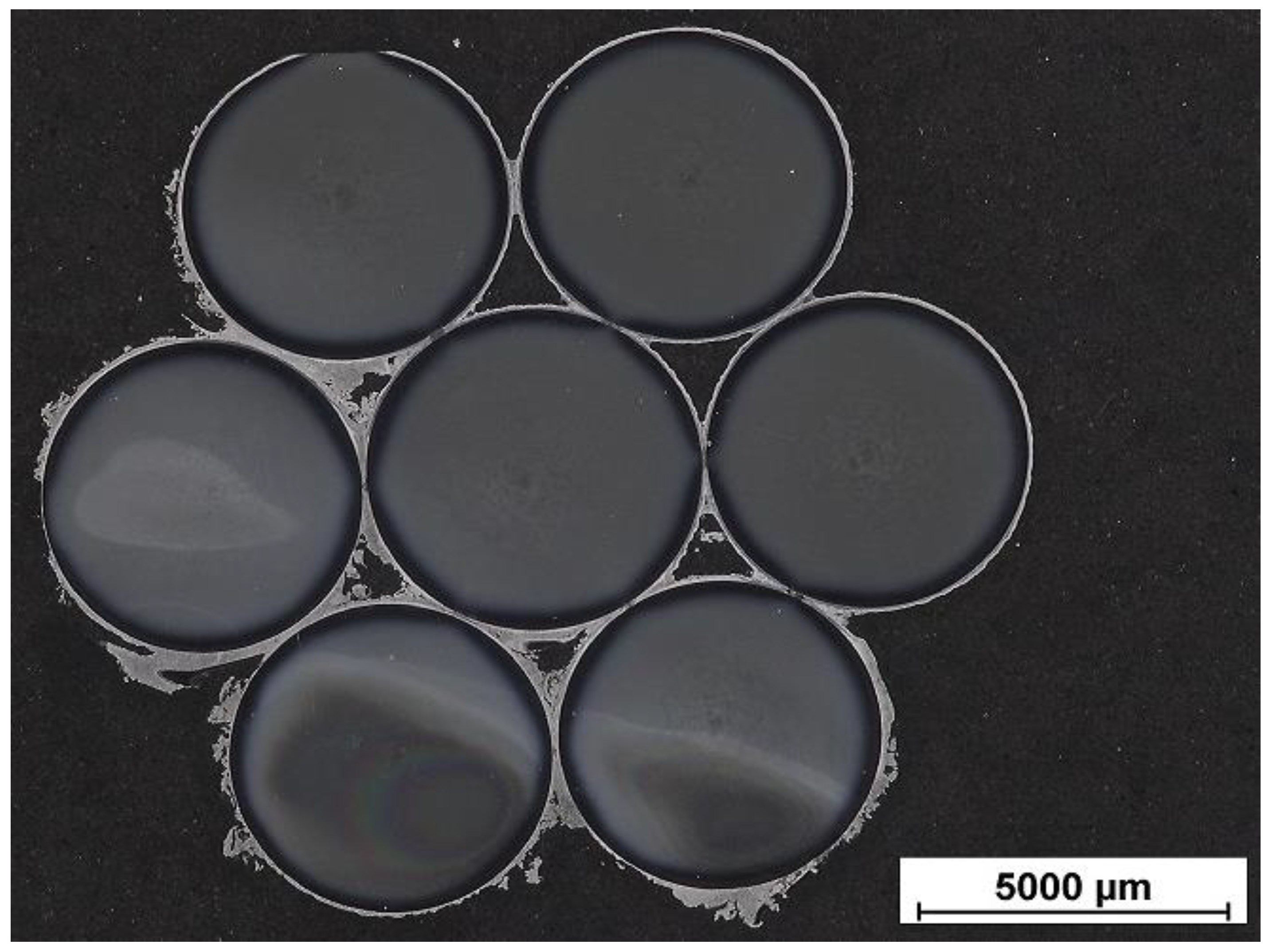
A typical example of the thickness and continuity of the HDG coating on the surface of individual wires taken from strands of the prestressing reinforcement is shown in Figure 8 (cross-section taken by optical microscopy). The surface of the outer wires of the prestressing reinforcement exhibited uniform coating coverage. However, the thickness of the coating was locally very rough—a local increase of up to 400% compared to the mean thickness. This significantly increased the friction of the surface of the test reinforcement, which can affect the increase in the bond strength of the coated reinforcement with the concrete [6,14,42,43]. The differences in coating thickness were related to the locally different reactivity of the steel surface. The inhomogeneity of carbon and silicon representation in the steel may influence this. An increased manganese content in the steel should not play a role in this regard [44]. However, the non-uniformity of the distribution of crystal lattice defects in the steel, the local surface cleanliness, and possibly the distribution of internal stresses in the steel of prestressing strands can be discussed. A significant thickness of the HDG coating was often detected at contacts of the outer wire surfaces. Due to the higher thickness of the coating, cracking once a strand was prestressed occurred (Figure 9A). These cracks can cause the coating to spall off from the steel surface during the handling and storage of the reinforcement. A detailed study of the surface of the inner and outer wires revealed localized coating delaminations (see Figure 9B). Both locally high thickness and cracking of the coating can reduce the barrier protection properties of the coating on the surface of the prestressing reinforcement. The corrosion products can cause the debonding of other coating parts in a short exposure time due to stress cracking [45,46].
Imaging the cross-sections of the coating of an outer and inner (Figure 10) wire of the prestressing reinforcement revealed that a continuous HDG coating with a thickness of approximately 65 µm formed locally (typical locations shown) on the steel surface. The outer wires exhibited the usual coating composition of single Fe-Zn intermetallic phases (see Figure 3) and continuous outer η layers [25,26,27,28,29,47,48]. However, the thickness of that phase was locally less than 10 µm, which is the necessary thickness for the formation of a protective layer from the corrosion products on the dominating Ca[Zn(OH)3]2·2H2O base [6,14,22,49,50]. However, the thickness of the coating on the surface of the inner wire was slightly higher—by about 10%. It appeared that the composition of the coating was atypical, i.e., the Γ phase (i.e., Γ + Γ1), the δ phase (δ1k + δ1p), and the outer layer was a palisade structure of the ζ phase (FeZn13). The ζ phase also showed a slightly higher thickness than usual. The outer layer from the η phase was absent (only local spots were observed). Thus, the HDG coating had a similar composition as if it were formed on silicon-killed steel (with Si content in the Sandelin region, i.e., 0.03–0.12 wt. %) [14,26,51,52]. The hydrogen overvoltage on the surface of the ζ phase was lower than on the surface of the η phase, accelerating the kinetics of hydrogen gas formation [30,31,32,53]. Earlier experimental works indicated that the hydrogen evolution could significantly compromise the integrity of the coating, thereby increasing the likelihood of compressive stresses causing transverse cracks, a significant hydrogen embrittlement of the coating, and susceptibility to brittle fracture [14,53,54]. The difficult accessibility of the steel surface for the zinc melt was a major contributor to the atypical coating composition on the inner wire of the prestressing reinforcement.
The results of surface roughness (Ra) measurements of uncoated and hot-dip galvanized prestressing steel wires are shown in Figure 11. The results indicate that the surface roughness (measured in the longitudinal direction) of hot-dip galvanized steel is higher than that of uncoated steel (approximately three times). Although the resulting coating is metallic sheen and the grain morphology is visually fine and uniform (produced after the samples are removed from the hot-dip galvanized bath). Similar values of Ra in the case of hot-dip galvanized and uncoated plain bars steel have been measured previously [6]. However, it can be considered that the surface roughness of single-strand hot-dip galvanized wires in strand (coating of the whole strand) will be higher (see Figure 8).
In general, it can be summarized that hot-dip galvanizing of whole strands was disadvantageous with regard to optimum protective properties. A metallographic analysis revealed a non-uniform coating thickness, the local absence of coating on the steel surface (between the outer and inner wires of reinforcement), and the formation of coating without a continuous η phase layer (on the surface of the inner wire of the prestressing reinforcement). To ensure the formation of a continuous coating of hot-dip galvanizing with an external η phase layer (solid solution of iron in zinc), it is necessary to hot-dip galvanize the individual wires of the prestressing reinforcement separately and then form the prestressing strain reinforcement.

3.2. Open-Circuit Potential Measurements

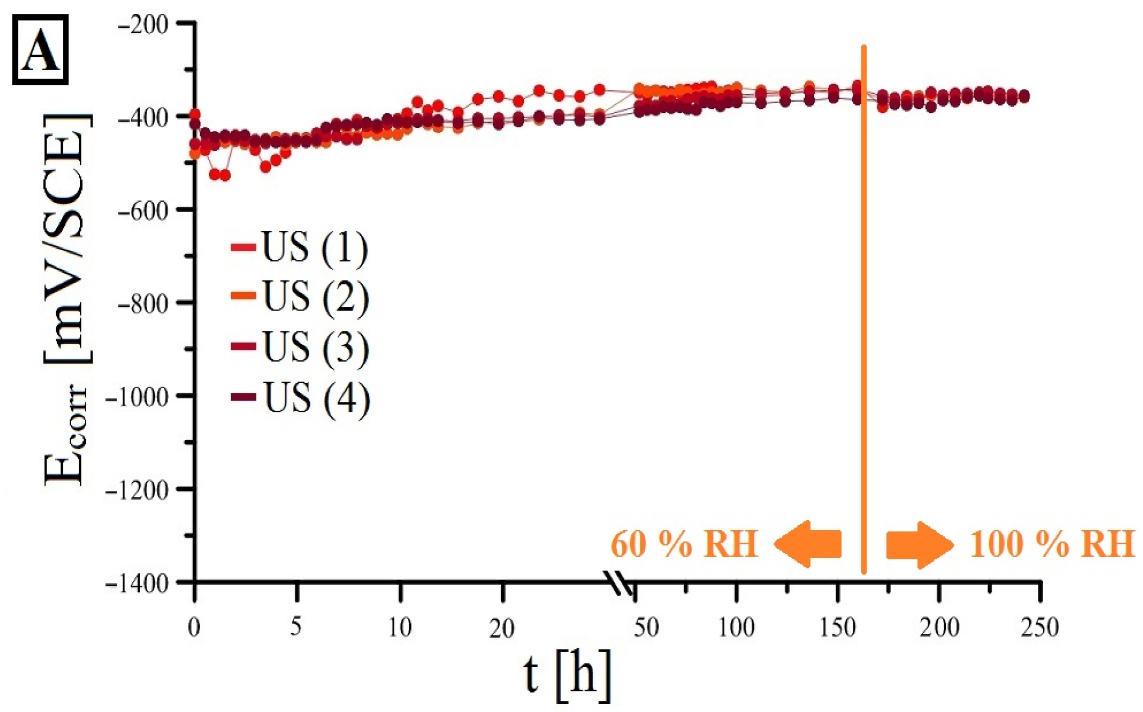
The time development of the open-circuit potential of uncoated steel (results for uncoated steel, US, in red color) and hot-dip galvanized steel, HDG (in blue color), are shown in Figure 12. The US values gradually increased over the time (up to 250 h here) interval, and the effect of keeping the samples under a water level (after ~170 h) was insignificant (a decrease in values of at most 50 mV/SCE). Thus, it is clear that relatively quickly after the experiment started, the surface of the uncoated steel was covered by a continuous natural passive layer, which was related to the high alkalinity of the cement paste pore solution (very likely pH > 13.0). This fact is described in detail in the literature [6,14,55,56,57,58]. The passive layer of usual thickness of around 15 nm consists of an inner protective layer probably composed of Fe3O4 and an outer significantly less protective layer of Fe2O3 [59,60,61,62]. Such a passive protective layer guarantees the corrosion of uncoated steel at a negligibly low corrosion rate, unaffecting the service life of concrete structures [14].
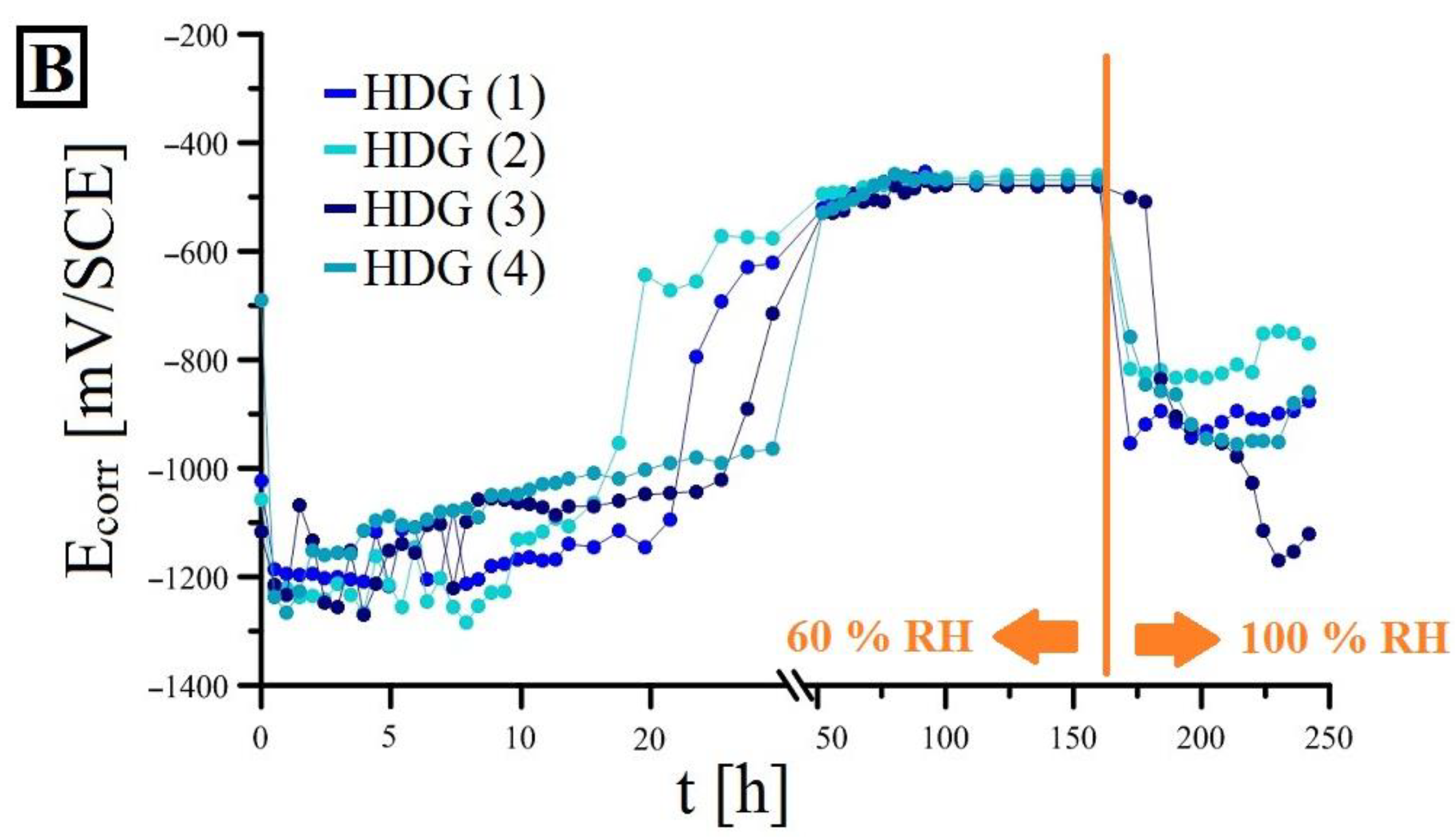
The time development of the open-circuit potential of HDG steel in the cement paste showed significant changes in the Ecorr values with exposure time, and compared to uncoated steel, they were significantly dependent on the RH of the environment. At the beginning of exposure, all four samples corroded under hydrogen evolution (see Equation (2)) at an open-circuit potential of about −1200 mV/SCE. This was observed in both model concrete pore solutions (containing Ca2+) and real normal-strength concrete [6,13,14,22,49,50,63,64]. After about 20 h, there was a sudden increase in Ecorr values up to about −500 mV/SCE and most likely a significant reduction in the corrosion rate of the HDG specimens.
Since the open-circuit potential of the HDG samples after this exposure time exceeded the threshold of −990 mV/SCE, the corrosion process proceeded with a cathodic oxygen reduction according to Equation (3).
1 2 O 2 + 2 e + H 2 O 2 O H
The limiting value of −990 mV/SCE for the corrosion of HDG steel in the alkaline environment of concrete is expressed from the equilibrium potential Eeq for Equation (2). The actual expression follows from the Nernst equation (see Equation (4) through Equation (6)) [6].
E e q = E 0 R T z F · l n a H 2 · a O H 2 a H 2 O 2 ; E 0 = 0.828 V
E e q = 0.828 + 0.059 14 p H = 0.059 · p H
E a q ( 2 H 2 O + 2 e H 2 + 2 O H ) = 990 m V / S C E
According to some authors, this is caused by the formation of a passive layer of Ca[Zn(OH)3]2·2H2O (CHZ), which effectively passivates the surface of HDG steel up to about pH 13.3 [13,14,22,49,63,64]. According to other authors, the passivity is not provided by the formation of CHZ but by the lack of water penetration at the surface of the HDG steel. These authors assume that sufficient protective passive drilling is formed not only by CHZ but also by ZnO and Zn(OH)2 (the phase precipitating between the pores of CHZ) [65,66]. The formation of the protective passive layer, in this case, is related to kinetic parameters (mainly ion transport to the surface of the coated steel). The thermodynamic stability of the protective layer of corrosion products strongly depend on the SO42−, Cl ion content, and pH of the concrete pore solution [67,68,69,70].
However, after the samples are submerged under water at about 170 h, the open-circuit potential values decreased. For one of four HDG samples, the Ecorr value even dropped below the threshold value of −990 mV/SCE. This again allowed for the progress of corrosion damage of HDG steel under hydrogen evolution at a very significant rate. The decrease in the measured values was related to facilitating water access to the corroding surface. Thus, it was evident that even after 170 h of exposure, a layer of corrosion products did not provide complete corrosion protection in a passive state. Moreover, this was observed even for specimens with wires coated separately, exhibiting an optimal composition with an outer layer formed from the η phase (Figure 10). However, locally, the thickness of the η phase may have been significantly lower than the specified critical value (10 µm) for passivation, and the transition to corrosion in the passive state on Fe-Zn intermetallic phases was very difficult [14,22,30,32,71,72].
The results presented in this section indicate that the transition of the surface of HDG steel in real concrete to a passive state may be somewhat imaginary and unrelated to the formation of a compact CHZ layer. Conversely, the lack of liquid water (consumed by cement hydration) at the surface of HDG steel may be related to the increase in Ecorr, accompanied by a decrease in corrosion rate. A passive layer with a significant barrier protection effect may form significantly later.
However, the Ecorr(t) values demonstrated that HDG conventional prestressing reinforcement corroded in real concrete under hydrogen evolution for a significant time (at least 20 h), which may be reflected in an increase in the porosity of the cement paste at the interface (ITZ). This increase in the porosity of the cement paste may be related to a decrease in the bond strength of the reinforcement in concrete [6,7,14,15,16].

3.3. Bond Strength

The effect of corrosion of HDG steel under hydrogen evolution on bond strength in concrete is often discussed in the literature. The evolution of gas penetrates the cement paste in the interfacial transition zone. This increases the porosity, which significantly reduces the proportion of the surface area of the reinforcement occupied by the cement paste. This leads to a reduction in the adhesion force fad that contributes to bond strength Tc,i according to Equation (7) [6,14]:
T c , i = i f a d + i f f + i f σ
The friction force (ff) differed for the US and HDG specimens as the hot-dip galvanizing process increases steel roughness [6,73,74]. This was confirmed in Figure 11. It can be concluded that an increased value of Ra (surface roughness) increased the bond strength of the HDG specimens in concrete. The effect of mechanical resistance of the concrete cover layer (fσ) on bond strength is generally significant. In our case, it was assumed that the fσ component was approximately the same for both specimens. Since it may apply that fσ > fad for this type of reinforcement, the negative effect of hydrogen evolution on bond strength may be less critical in such cases [6,14].
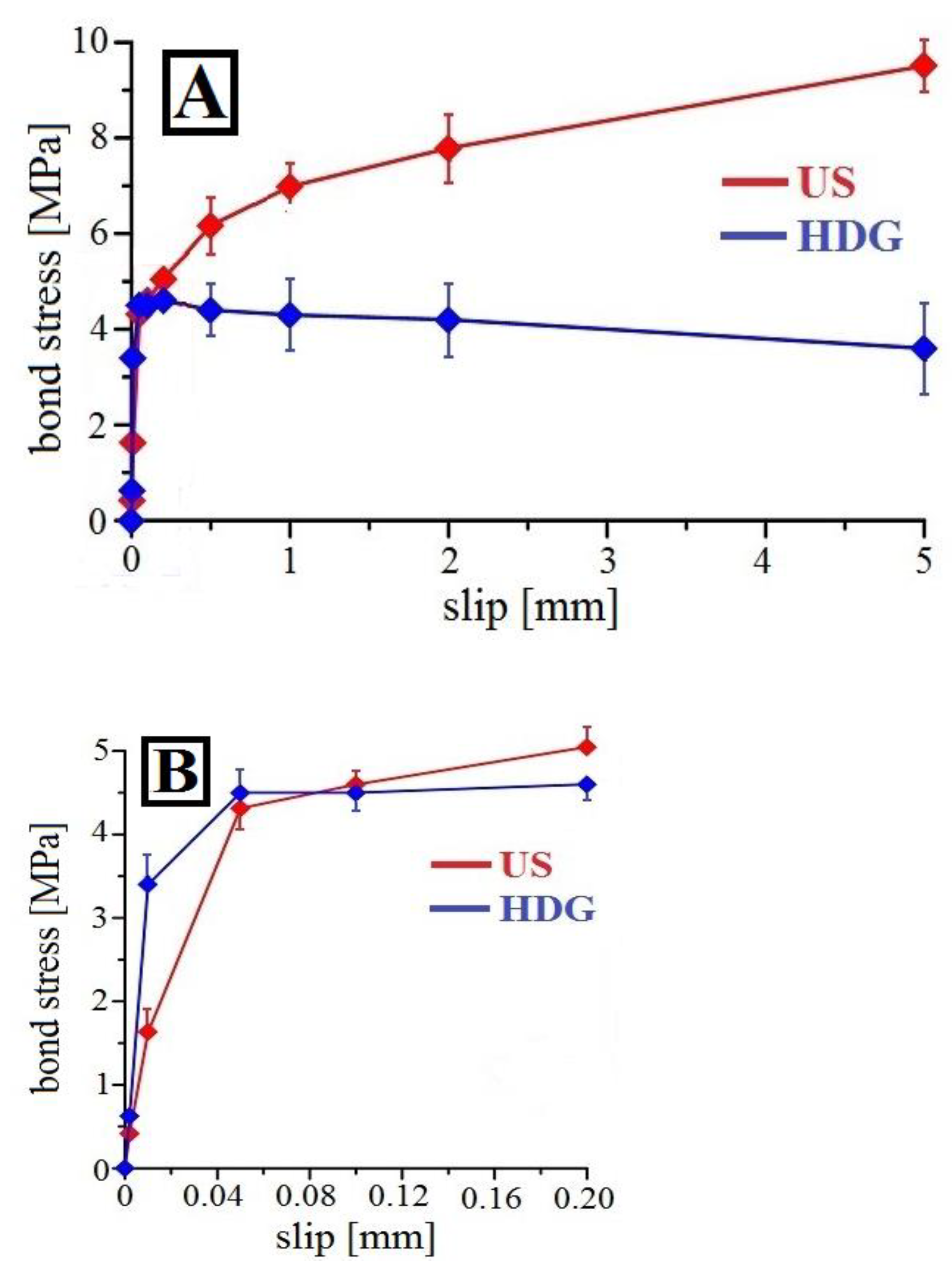
The results of the bond strength (pull-out) tests for both types of specimens are displayed in Figure 13. Bond stress–slip curves for uncoated steel (in red) have a typical parabolic shape with increasing bond strength for prestressing strands [75,76,77]. For HDG specimens, the bond stress–slip curve attained a global maximum (~4.5 MPa at 0.04 mm slip). Afterwards, there was a gradual decrease in bond stress values as the slip value increased. However, at very low slip values (up to the global maximum of the curve), the increase in bond strength of the HDG strands was more significant than for uncoated steel. This was mainly attributed to the locally increased surface roughness (Ra) (Figure 11). Additionally, there may have been an increase in the surface roughness of the samples due to the formation of CHZ crystals [10,78,79].
Due to shear loading during the pull-out test (already at low slip values), longitudinal cracks likely formed between the corrosion products of the coating (or the top rough layer) and the cement paste, and consequently, the reinforcement was easier to be pulled out of the normal strength concrete cubic specimen. In general, the bond strength of HDG strands is lower than that of uncoated steel. The porous structure of the cement paste caused by hydrogen evolution at the interfacial transition zone (ITZ) was only manifested at higher slip values (bond strength of ~4.5 MPa) when the bond strength was significantly reduced. However, the influence of other factors on the bond strength of coated prestressing steel strands with concrete could not be excluded.
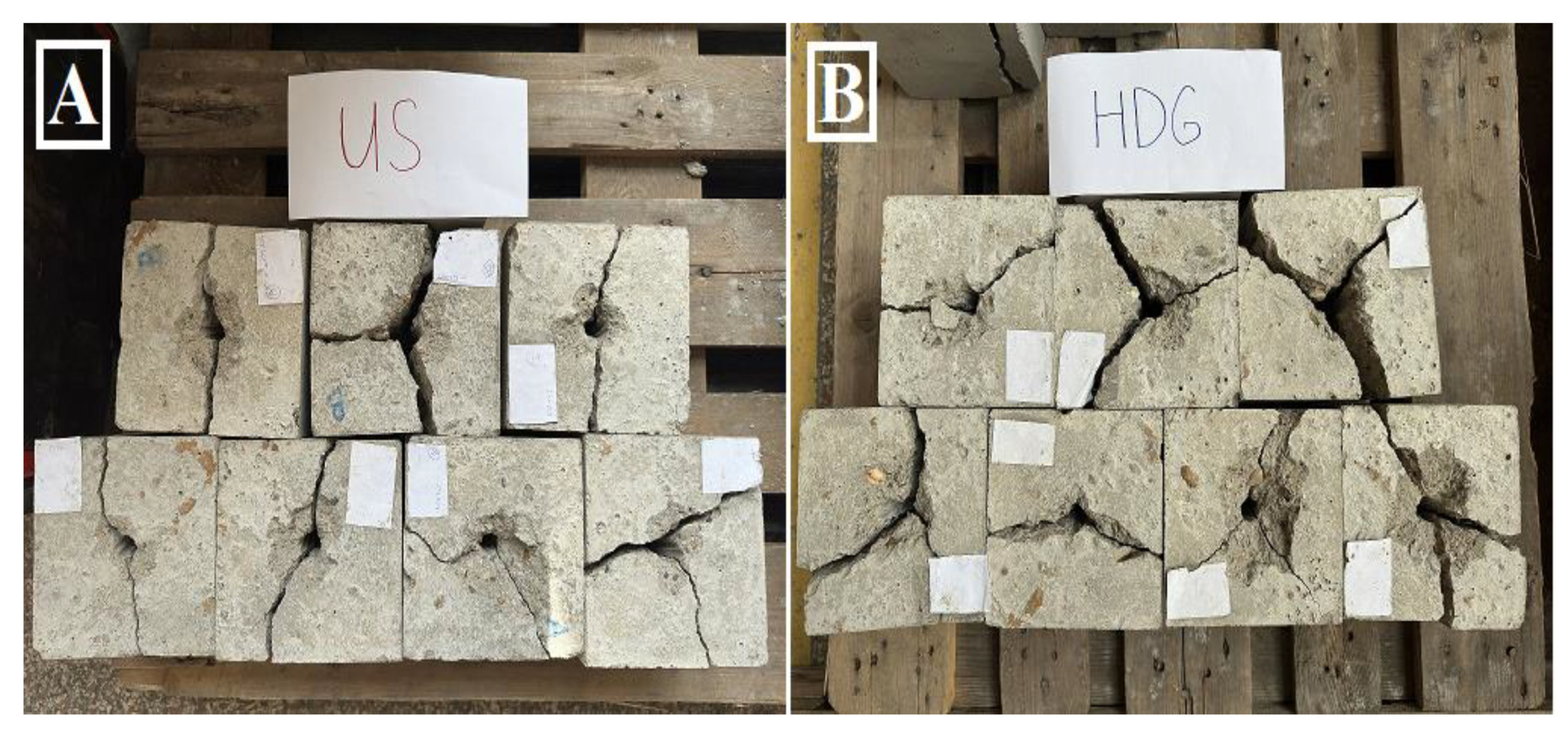
The failure pattern after pull-out tests for both types of strands was further investigated—see Figure 14. Uncoated steel and hot-dip galvanized steel showed a clear splitting failure, as the cubic specimens for the pull-out test were without transversal reinforcement [80,81]. A visual examination of failure surfaces revealed no significant differences between the two types of specimens regarding crack sizes and crack propagation. The reduction in bond strength in normal-strength concrete (NSC) was due to the changes caused by hydrogen formation or precipitation of the CHZ-based corrosion products. Note that the deceleration of cement paste hardening in the ITZ due to zinc corrosion products may partly reduce bond strength. Zinc corrosion products can significantly inhibit the hydration of silicate/aluminate-based cement, negatively affecting the mechanical properties of concrete [82,83,84,85].
Figure 15 shows the surface of hot-dip galvanized coating on surface of prestressing steels after bond strength test (pull-out test). The increased surface roughness (see Figure 11) of the hot-dip galvanized reinforcement conditions the formation of cracks/fracture patterns mainly on the highest surface (perpendicular to the reinforcement axis) in contact with normal-strength concrete. Locally, cracks/fracture patterns were detected in the η phase (solid solution of iron in zinc)-see Figure 15A. However, locations with cracks through zinc corrosion products were also detected, suggesting that the failure mode may partially pass in this area. Quite exceptionally, carcks/fracture pattern in ζ phase (FeZn13) were detected. This phase is significantly more brittle than the η phase.

3.4. Cement Paste Porosity

Figure 16 shows examples of the ITZ of the cement paste from uncoated steel. The porosity of the phase interface from uncoated steel exhibited low porosity, typical for the cement paste with a water-to-cement ratio w/c = 0.35. The cracks across the ITZ were caused by the absence of reinforcement and aggregate in the cement paste and the tensile forces required to pull out the strands. The cement paste was marginally locally porous due to imperfect compaction.
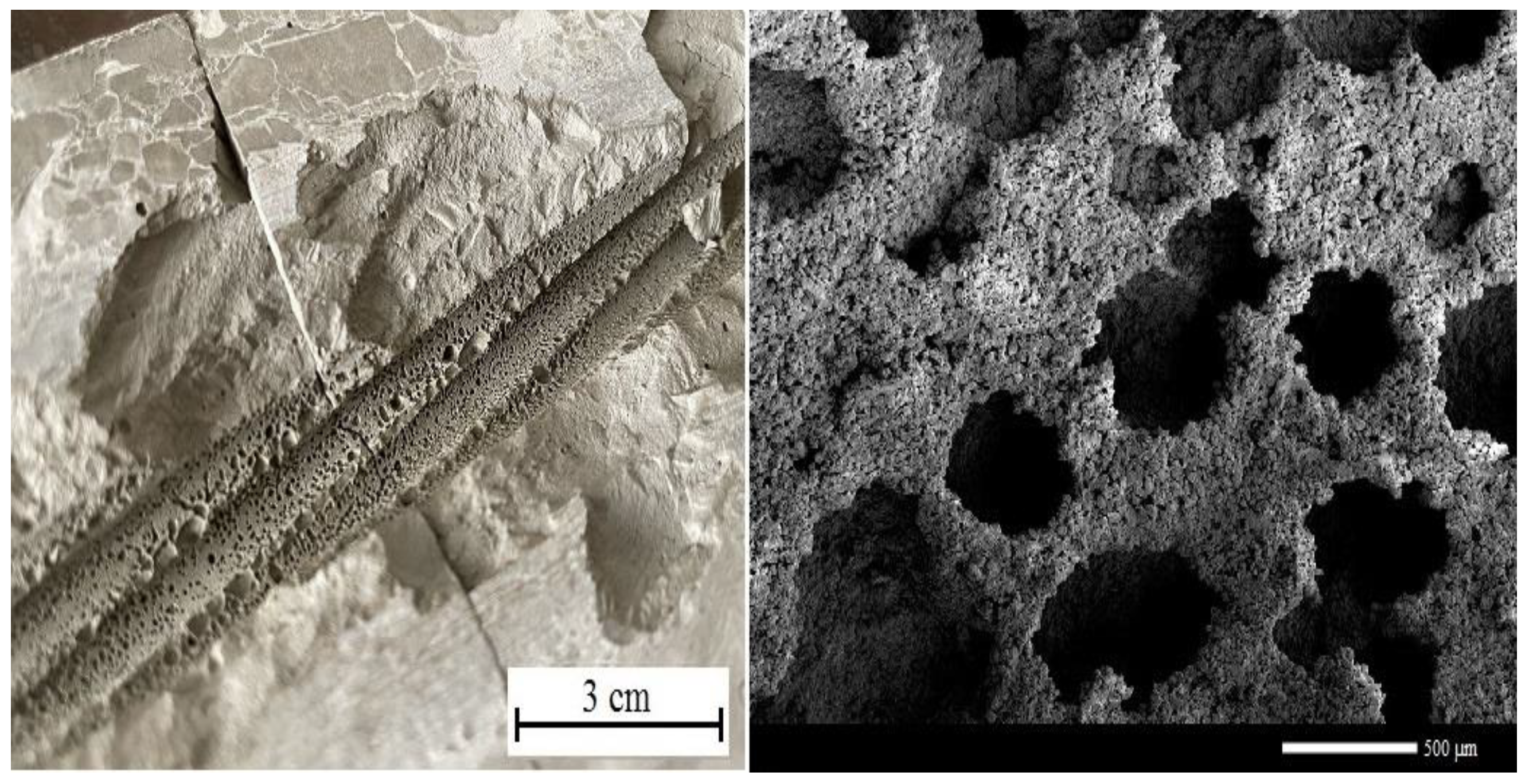
Figure 17 displays the ITZ of HDG prestressing steel. The porosity of the cement paste was significantly larger. It is also evident that the pores formed were due to the corrosion of the coating under hydrogen evolution. Compared to the literature [9,53,71,86], it is evident that the corrosion products of zinc could not fill the pores in the cement paste formed by hydrogen evolution after 28 days of concrete aging. On the contrary, the results of the present work confirmed the findings of other works, which showed that zinc corrosion products were not able to fill the pores formed by hydrogen after 28 days of concrete (cement paste) aging [87,88], after 1 year of aging [6,14], even after 4 years of aging [89]. Hydrogen-formed pores (see Figure 17) had locally significant dimensions (hole diameter)—up to hundreds of micrometers. The total depth of the pores varied; corrosion products partly filled some. The total pore depth was expected to be less than the hole diameter (less than hundreds of micrometers). The reason for this is the partial possibility of gas leakage along the phase interface (steel/cement paste) and the partial filling of the bottom of the pores with zinc corrosion products.
Figure 18 presents the overall results of the comparative image analysis (surface occupied by pores) of the ITZ cement paste from both types of strands. Corrosion of the HDG strands under hydrogen evolution caused an increase in the porosity of the cement paste up to 20 times. Therefore, this may have been the leading cause of the observed reduction in bond strength of the HDG strands in normal-strength concrete (Section 3.3).
Figure 19 shows the result of X-ray diffraction (diffraction pattern) of corrosion products on the surface of hot-dip galvanized prestressing steel reinforcement after 28 days of curing in cement paste. Due to the circular surface of the reinforcement, the analysis was very difficult, and even a semi-quantitative comparison of the representation of the different phases would be burdened with a significant error. Notwithstanding this fact, it was clear that the detected surface had only a very thin layer of η (1-Zn) phase, as the presence of ζ (2-FeZn13) phase was quite evident. Among the corrosion products, the expected ZnO and CHZ (Ca[Zn(OH)3]2·2H2O) phases [6,22,49,50,63,64,67] were observed. According to the results of the pull-out test, it was clear that the CHZ phase was unlikely to contribute significantly to the bond strength [10,14]. The presence of ZnO in larger amounts indicated the higher alkalinity of the cement paste pore solution [14,50,63,64,65]. Also present were portlandite (Ca(OH)2) and calcite (CaCO3) phases, whose origin was from cement paste.
It followed that an additional topcoat of the surface of the HDG strands was necessary to limit the corrosion of the coating under hydrogen evolution in contact with fresh concrete. Previous work suggested that conversion coatings [11,13,14,90,91], organic coatings [92], and bitumen-based coatings [93] could be successfully used. Without topcoats, the bond strength of HDG strands in concrete (cement paste or cement grout) may be significantly reduced.
Corrosion of the hot-dip galvanized coating on the surface of the prestressing reinforcement in OPC led to the development of the hydrogen gas and a small reduction in coating thickness. Despite this, the coating commonly keeps its barrier protection properties. The observed reduction in bond strength due to a significant increase in the porosity of the cement paste in ITZ may be critical in cases where transfer and anchorage lengths provided by design are insufficient, e.g., when outdated design approaches are taken into account. It may then be required to increase the bond strength by extending anchor lengths.
In contrast, bond strength reduction may have an unimportant effect on the load-bearing capacity of the structures for which design provisions provide a large reliability margin and where bond strength is only partly utilized at ultimate limit states. In other cases, mild steel reinforcement may provide additional contribution to the load-bearing capacity when bond strength between tendons and the cement paste or grout is reached.
Corrosion of prestressing reinforcement is initiated when the concentration of chloride anions exceeds a threshold value. The level of local corrosion damage to the surface of the prestressing reinforcement is determined by chloride ion concentration, voids in or absence of grout, total wetting time, and the possible presence of other corrosion stimulants (e.g., SO2, SO42−). A wide range of conditions that may occur in situ is difficult to capture by laboratory tests and consequently, the results presented in this study needs to be considered with caution. Regardless of this, hot-dip galvanized coatings exhibited a substantially higher resistance to chloride anions, and it can be concluded that they could significantly extend the time to activation of the underlying steel under in situ conditions, thereby extending service life of prestressing reinforcement. This positive effect was slightly reduced by the hydrogen-induced pores in the cement paste that allowed chloride anions to accumulate along the surface.
A challenge for further research is the investigation into the effect of prestressing—when bond strength is measured on hydrogen development-affected prestressed tendons, it is expected that a lower porosity of the cement paste would be reached at the same amount of developed hydrogen. However, this hypothesis needs to be verified by subsequent studies.
In combination with frequent stress cycles, the aforementioned pores and caverns in the cement paste along with the accumulated chloride anions may also contribute to the formation and propagation of fatigue cracks. This effect is expected to be relatively minor in comparison with the extension of service life provided by the coating; yet, this remains to be confirmed by further research.
Regarding implications for applications with other materials, continuous galvanizing is deemed to be slightly more efficient but excessively expensive for routine applications in civil engineering. Applications based on rapidly developing ultra-high-performance concretes (UHPCs) are foreseen—as the material is much denser compared to NSC, much lower porosities in the paste are expected, implying a lower reduction in bond strength.
Hot-dip galvanized coating can extend service life particularly of the structures susceptible to chloride-induced corrosion. In order to prevent hydrogen-induced corrosion of the coating, it is, however, necessary to apply an additional coating of the prestressing reinforcement—see above.
Subsequent life cycle-cost studies should help to identify situations in which hot-dip galvanization should be applied to prestressing reinforcement. It is expected that these will include structures in chloride-laden environment, in particular those with vertically curved tendons, with a significant probability of early chloride ingress (i.e., for the first five years approximately).

4. Conclusions

Focusing on hot-dip galvanized prestressing steel strands, this study investigated the effect of their corrosion in fresh normal-strength concrete under hydrogen evolution on bond strength. Initially, whole strands of conventional prestressing reinforcement were hot-dip galvanized. The corrosion behavior of individual coated wires was then studied by measuring the time development of the open-circuit potential in the cement paste. The effect of hydrogen evolution on the porosity of the cement paste at the interfacial transition zone (ITZ) was verified by image analysis.
Hot-dip galvanizing of whole strands is an inefficient method of corrosion protection, because this method does not ensure the formation of a uniform coating of similar composition for all wires in the strand. This coating exhibits lower corrosion resistance and stability in the concrete environment.
Corrosion of hot-dip galvanized prestressing steel in cement paste is accompanied by hydrogen evolution for a very long time. The formation of corrosion products based on Ca[Zn(OH)3]2·2H2O may not provide sufficient surface passivation. Corrosion of hot-dip galvanized prestressing steel under hydrogen evolution may occur again after re-submergence of samples under water level.
It was shown that the hydrogen evolution increased the porosity of the cement paste at the interfacial transition zone (ITZ). This fact significantly contributed to the reduction in bond strength in normal-strength concrete, although hot-dip galvanizing prestressing steel reinforcement significantly increased surface roughness (Ra).
Based on these findings, it is concluded that for civil engineering applications, it is necessary to coat wires individually (batch hot-dip galvanizing process) and subsequently form the strand. To prevent corrosion of the coating with hydrogen evolution in cementitious materials, it is necessary to additionally protect HDG steel by other coatings that are sufficiently stable in an alkaline environment. It is recommended that wires be individually coated in this way (hot-dip galvanized coating as well as topcoating).

Author Contributions

Methodology, K.H.; validation, V.S.; formal analysis, T.C.; investigation, P.P., T.C. and N.P.; resources P.P. and N.P.; writing—original draft, P.P. All authors have read and agreed to the published version of the manuscript.

Funding

This research was supported by the Czech Science Foundation under grant no. 24-12783S.

Data Availability Statement

Data are contained within the article.

Conflicts of Interest

The authors declare no conflicts of interest.

References

  1. Borges da Fonsêca, M.S.D.A.; Meira, G.R. Accelerated chloride-induced corrosion of hot-dipped galvanized reinforcements and its influence on the bond strength to concrete. Constr. Build. Mater. 2024, 426, 136123. [Google Scholar] [CrossRef]
  2. Al-Negheimish, A.; Hussain, R.R.; Alhozaimy, A.; Singh, D.D.N. Corrosion performance of hot-dip galvanized zinc-aluminium coated steel rebars in comparison to the conventional pure zinc coated rebars in concrete environment. Constr. Build. Mater. 2021, 274, 121921. [Google Scholar] [CrossRef]
  3. Xie, W.; Li, J.; Li, Y. Electrochemical corrosion behavior of carbon steel and hot dip galvanized steel in simulated concrete pore solution with different pH values. Mater. Sci. 2017, 23, 280–284. [Google Scholar]
  4. Fagueira, R.B.; Silva, C.J.R.; Pereira, E.V. Hybrid sol-gel coatings for corrosion protection of hot-dip galvanized steel in alkaline medium. Surf. Coat. Technol. 2015, 265, 191–204. [Google Scholar] [CrossRef]
  5. Zheng, H.; Dai, J.G.; Poon, C.S.; Li, W. Influence of a superplasticizer on initial corrosion of galvanized steel bars in concrete pore solution. J. Mater. Civ. Eng. 2021, 33, 04021113. [Google Scholar] [CrossRef]
  6. Pokorný, P.; Pernicová, R.; Tej, P.; Kolísko, J. Changes of bond strength properties of hot-dip galvanized plain bars with cement paste after 1 year of curing. Constr. Build. Mater. 2019, 226, 920–931. [Google Scholar] [CrossRef]
  7. Gallego, A. Comparison between concrete-black steel and concrete-galvanized steel bond via the pull-out test supplied with acoustic emission. In Proceedings of the European Working Group on Acoustic Emission, Berlin, Germany, 15–17 September 2004; pp. 761–767. [Google Scholar]
  8. Hamad, B.S.; Jumaa, G.K. Bond strength of hot-dip galvanized hooked bars in high strength concrete structures. Constr. Build. Mater. 2008, 22, 2042–2052. [Google Scholar] [CrossRef]
  9. Belaïd, F.; Arliguie, G.; François, R. Porous structure of ITZ around galvanized and ordinary steel reinforced. Cem. Concr. Res. 2001, 31, 1561–1566. [Google Scholar] [CrossRef]
  10. Fratesi, R.; Moriconi, G.; Coppola, L. The Influence of Steel Galvanization on Rebars Behaviour in Concrete. In Corrosion of Reinforcement in Concrete Construction; The Royal Society of Chemistry: London, UK, 1996; pp. 630–640. [Google Scholar]
  11. Arenas, M.A.; Casado, C.; Nobel-Pujol, V.; Damborenea, J. Influence of the conversion coating on the corrosion of galvanized steel. Cem. Concr. Compos. 2006, 28, 267–275. [Google Scholar] [CrossRef]
  12. Bikulčius, G. Corrosion behaviour in alkaline media of steel with various conversion coatings in concrete. J. Appl. Chem. 2003, 76, 1809–1813. [Google Scholar]
  13. Sanchez, M.; Alonso, M.C.; Cecilio, P.; Montemor, M.F.; Andrade, C. Electrochemical and analytical assessment of galvanized steel reinforcement pre-treated with Ce and La salts under alkaline media. Cem. Concr. Compos. 2006, 28, 256–266. [Google Scholar] [CrossRef]
  14. Pokorný, P.; Kouřil, M. Predicted corrosion performance of organofunctional silane coated steel reinforcement for concrete structures: An overview. Buildings 2024, 14, 1756. [Google Scholar] [CrossRef]
  15. Prüfbericht. Bundesanstalt für Materialforschung und-Prüfung, Prüfung von einem Nachbehandlungsmittel an Feurverzinktem Betonstahl; BAM: Bam, Iran, 2018; pp. 1–6. [Google Scholar]
  16. King, D. Pre-Stressed Concrete Structure with Galvanized Reinforcement. U.S. Patent US 10,753,095 B2, 25 August 2020. [Google Scholar]
  17. EN 206 + A2. Concrete—Specification, Performance, Production and Conformity. ÚNMZ: Prague, Czech Republic, 2020.
  18. Hájková, K.; Šmilauer, V.; Jendele, L.; Červenka, J. Prediction of reinforcement corrosion due to chloride ingress and its effects on serviceability. Eng. Struct. 2018, 174, 768–777. [Google Scholar] [CrossRef]
  19. Liu, C.-Y.; Chou, J.-S. Bayesian-optimized deep learning model to segment deteroriation patterns underneath bridge decks photographed by unmanned aerial vehicle. Autom. Constr. 2023, 146, 104666. [Google Scholar] [CrossRef]
  20. Morgese, M.; Ansari, F.; Domaneschi, M.; Cimellaro, G.P. Post-collapse analysis of Morandi’s Polcevera viaduct in Genoa Italy. J. Civ. Struct. Health Monit. 2020, 10, 69–85. [Google Scholar] [CrossRef]
  21. Dorsten, V.; Hunt, F.F.; Preston, H.K. Epoxy coated seven-wire strand for pre-stressed concrete. Pre-Stress. Concr. Inst. 1984, 29, 120–129. [Google Scholar]
  22. Andrade, C.; Macias, A. Galvanized Reinforcement in Concrete, Surface Coatings-2; Wilson, A.D., Nicholson, J.W., Prosser, H.J., Eds.; Elsevier Applied Science Publishers Ltd.: Amsterdam, The Netherlands, 1988; pp. 137–182. [Google Scholar]
  23. Bellezze, T.; Malavolta, M.; Quaranta, A.; Ruffini, N.; Roventi, G. Corrosion behaviour in concrete of tree differently galvanized steel bars. Cem. Concr. Compos. 2006, 28, 246–255. [Google Scholar] [CrossRef]
  24. Sistonen, E. Service Life of Hot Dip Galvanized Reinforcement Bars in Carbonated and Chloride Contaminated Concrete. Ph.D. Thesis, Structural Enginnering and Building Technology, Helsinki University of Technology, Helsinki, Finland, 2000. [Google Scholar]
  25. Vontorová, J.; Mohyla, P.; Kreislová, K. Quality of zinc coating formed on structural steel by hot-dip galvanizing after surface contamination. Coatings 2024, 14, 493. [Google Scholar] [CrossRef]
  26. Marder, A.R. The metallurgy of zinc-coated steel. Prog. Mater. Sci. 2000, 45, 191–271. [Google Scholar]
  27. Okamoto, N.L.; Yasuhara, A.; Inui, H. Order-disorder structure of the δ1k phase in the Fe-Zn system determined by scanning transmission electron microscopy. Acta Mater. 2014, 81, 345–357. [Google Scholar] [CrossRef]
  28. Okamoto, N.L.; Tanaka, K. Structure refinement of the δ1p phase in the Fe-Zn system by single crystal X-ray diffraction combined with scanning transmission electron microscopy. Acta Crystallogr. 2014, 70, 275–282. [Google Scholar]
  29. Yu, J.; Liu, J.; Zhou, W.; Zhang, J.; Wu, J. Cross-sectional TEM observation of iron—Zinc intermetallic Γ and Γ1 phases in commercial galvannealed IF steel sheets. Mater. Des. 2007, 28, 249–253. [Google Scholar] [CrossRef]
  30. Maahn, E.; Sorensen, B. The Influence of microstructure on the corrosion properties of hot–dip galvanized reinforcement in concrete. Corrosion 1986, 42, 187–196. [Google Scholar] [CrossRef]
  31. Bird, C.E. The influence of minor constituents in Portland cement on the behavior of galvanized steel in concrete. Corros. Prev. Control. 1964, 17–21. [Google Scholar]
  32. Lee, H.H.; Hiam, D. Corrosion resistance of galvannealed steel. Corrosion 1989, 45, 852–856. [Google Scholar] [CrossRef]
  33. prEN 10138-3; Pre-Stressing Steels—Part 3: Strand. European Committee for Standardization: Brussel, Belgium.
  34. Available online: https://wiegel.de/cs/standorte/cenkov/ (accessed on 18 September 2024).
  35. Kondraivendhan, B.; Bhattacharjee, B. Strength and w/c ratio relationship of cement based materials though pore features. Mater. Charact. 2016, 122, 124–129. [Google Scholar] [CrossRef]
  36. Kurda, R.; De Brito, J.; Silvestre, J.D. Water absorption and electrical resistivity of concrete with recycled concrete aggregates and fly ash. Cem. Concr. Compos. 2019, 95, 169–182. [Google Scholar] [CrossRef]
  37. Song, X.; Wu, Y.; Gu, X.; Chen, C. Bond behaviour of reinforcing steel bars in early age concrete. Constr. Build. Mater. 2015, 94, 209–217. [Google Scholar] [CrossRef]
  38. RILEM RC6; Bond Test for Reinforcement Steel. 2: Pull-Out Test. E & FN SPON: Paris, France, 1983.
  39. ASTM C234-91a; Standard Test Method for Comparing Concretes on the Basis of the Bond Developed with Reinforcing Steel. ASTM International: West Conshohocken, PA, USA, 1991.
  40. Matsumoto, K.; Wang, T.; Hayashi, D.; Nagai, K. Investigation on the pull-out behavior of deformed bars in cracked reinforced concrete. J. Adv. Concr. Technol. 2016, 14, 573–589. [Google Scholar] [CrossRef]
  41. Pistofidis, N.; Vourlias, G.; Konidaris, S.; Pavlidou, E.; Stergiou, A.; Stergioudis, G. Microstructure of zinc hot-dip galvanized coatings used for corrosion protection. Mater. Lett. 2006, 60, 786–789. [Google Scholar] [CrossRef]
  42. Khabaz, A. Analysis of sliding mechanism of straight steel fibers in concrete and determine the effect of friction. Arch. Civ. Mech. Eng. 2017, 17, 599–608. [Google Scholar] [CrossRef]
  43. Jiang, C.; Wu, Y.-F.; Dai, M.-J. Degradation of steel-to-concrete bond due to corrosion. Constr. Build. Mater. 2018, 158, 1073–1080. [Google Scholar] [CrossRef]
  44. Blumenau, M.; Norden, M.; Friedel, F.; Peters, K. Reactive wetting during hot-dip galvanizing of high manganese alloyed steel. Surf. Coat. Technol. 2011, 205, 3319–3327. [Google Scholar] [CrossRef]
  45. Persson, D.; Thierry, D.; Karlsson, O. Corrosion and corrosion products of hot dipped galvanized steel during long term atmospheric exposure at different sites world-wide. Corros. Sci. 2017, 126, 152–165. [Google Scholar] [CrossRef]
  46. Alvarenga, E.d.A.; Lins, V.F.C. Atmospheric corrosion evaluation of electrogalvanized, hot-dip galvanized and galvannealed intersticial free steels using accelerated field and cyclic tests. Surf. Coat. Technol. 2016, 306, 428–438. [Google Scholar] [CrossRef]
  47. Carpio, J.; Casado, J.A.; Álvarez, J.A.; Gutiérrez-Solana, F. Environmental factors in failure during structural steel hot-dip galvanizing. Eng. Fail. Anal. 2009, 16, 585–595. [Google Scholar] [CrossRef]
  48. Yu, Z.; Hu, J.; Meng, H. A review of recent developments in coating systems for hot dip galvanized steel. Front. Mater. 2020, 7, 74. [Google Scholar] [CrossRef]
  49. Andrade, C.; Holst, J.D.; Nürnberger, U.; Whiteley, J.D.; Woodman, N. Protection System for Reinforcement; CEB-Bulletin D’Information: Lousanne, Switzerland, 1992. [Google Scholar]
  50. Macías, A.; Andrade, C. Corrosion rate of galvanized steel immersed in saturated solutions of Ca(OH)2 in the pH range 12-13.8. Br. Corros. J. 1983, 18, 82–87. [Google Scholar] [CrossRef]
  51. Kania, H.; Mendala, J.; Kozuba, J.; Saternus, M. Development of bath chemical composition for batch hot-dip galvanizing—A review. Materials 2020, 13, 4168. [Google Scholar] [CrossRef]
  52. Bondareva, O.S.; Melnikov, A.A. Effect of silicon content in steel on the hot-dip zinc coating microstructure formation. IOP Conf. Ser. Mater. Sci. Eng. 2016, 156, 012015. [Google Scholar] [CrossRef]
  53. Yeomans, S.R. Galvanized Steel Reinforcement in Concrete, 2nd ed.; Elsevier: Canberra, Australia, 2004. [Google Scholar]
  54. Santos, P. Influencia de la Estructura Metalográfica y del tipo de Cemento en la Corrosion de Armaduras Galvanizadas. Ph.D. Thesis, Universidad Autónoma de Madrid, Madrid, Spain, 1986. [Google Scholar]
  55. Valcarce, M.B.; Vázquez, M. Carbon steel passivity examined in alkaline solutions: The effect of chloride and nitrite ions. Electrochim. Acta 2008, 53, 5007–5015. [Google Scholar] [CrossRef]
  56. Elsener, B. Macrocell corrosion of steel in concrete—Implications for corrosion monitoring. Cem. Concr. Compos. 2002, 24, 65–72. [Google Scholar] [CrossRef]
  57. Lu, P.; Kursten, B.; Macdonald, D.D. Deconvolution of the partial anodic and cathodic processes during the corrosion of carbon steel in concrete pore solution under simulated anoxic conditions. Electrochim. Acta 2014, 143, 312–323. [Google Scholar] [CrossRef]
  58. Eichler, T.; Isecke, B.; Bäßler, R. Investigations on the re-passivation of carbon steel in chloride containing concrete in consequence of cathodic polarization. Mater. Corros. 2009, 60, 119–129. [Google Scholar] [CrossRef]
  59. Williamson, J.; Isgor, O.B. The effect of simulated concrete pore solution composition and chlorides on the electronic properties of passive films on carbon steel rebar. Corros. Sci. 2016, 106, 82–95. [Google Scholar] [CrossRef]
  60. Freire, L.; Nóvoa, X.R.; Montemor, M.F.; Carmezim, M.J. Study of passive films formed on mild steel in alkaline media by the application of anodic potentials. Mater. Chem. Phys. 2009, 114, 962–972. [Google Scholar] [CrossRef]
  61. Volpi, E.; Olietti, A.; Stefanoni, M.; Trasatti, S.P. Electrochemical characterization of mild steel in alkaline solutions simulating concrete environment. J. Electroanal. Chem. 2015, 736, 38–46. [Google Scholar] [CrossRef]
  62. Song, Z.; Zhang, Y.; Liu, L.; Pu, Q.; Jiang, L.; Chu, H.; Luo, Y.; Liu, Q.; Cai, H. Use of XPS for quantitative evaluation of tensile-stress-induced degradation of passive film on carbon steel in simulated concrete pore solutions. Constr. Build. Mater. 2021, 274, 121779. [Google Scholar] [CrossRef]
  63. Macías, A.; Andrade, C. Corrosion of galvanized steel reinforcements in alkaline solutions. Part 1: Electrochemical results. Br. Corros. J. 1987, 22, 113–118. [Google Scholar] [CrossRef]
  64. Macías, A.; Andrade, C. Corrosion of galvanized steel reinforcements in alkaline solutions. Part 2: SEM study and identification of corrosion products. Br. Corros. J. 1987, 22, 119–129. [Google Scholar] [CrossRef]
  65. Menzel, K. Zur Korrosion von verzinktem Stahl in Kontakt mit Beton–IWB (Mitteilungen); Universität Stuttgart: Stuttgart, Germany, 1992. [Google Scholar]
  66. Wienerová, K.; Kouřil, M.; Stoulil, J. Koroze a ochrana zinkované oceli v prostředí betonu. Koroze Ochr. Mater. 2010, 54, 148–154. [Google Scholar]
  67. Macias, A.; Andrade, C. Stability of the calcium hydroxyzincate protective layer developer on galvanized reinforcements after a further increase of the pH value. Mater. Constr. 1986, 36, 19–28. [Google Scholar]
  68. Macias, A.; Andrade, C. Galvanized steel behaviour in Ca(OH)2 saturated solution containing SO4 ions. Cem. Concr. Res. 1987, 17, 307–316. [Google Scholar] [CrossRef]
  69. González, J.A.; Andrade, C. Effect of carbonation, chlorides and relative ambient humidity on the corrosion of galvanized rebars embedded in concrete. Br. Corros. J. 1982, 17, 21–28. [Google Scholar] [CrossRef]
  70. Andrade, C.; Macias, A. Influencia del contenido en álcalis de los cementos sobre la corrosión de armaduras galvanizadas. Mater. Constr. 1981, 184, 83–93. [Google Scholar] [CrossRef]
  71. Yeomans, S.R. Galvanized steel reinforcement—A prespect view, conference. In Proceedings of the Real World Concrete–Symposium of RN Swamy, Milwaukee, WI, USA, 4–9 June 1995; American Concrete Institute: Farmington Hills, MI, USA, 1995; pp. 57–70. [Google Scholar]
  72. Yeomans, S.R. Comparative Studies of Galvanized and Epoxy Coated Steel Reinforcement in Concrete; Research Report, No. R103; The University of New South Wales: Canberra, Australia, 1991; pp. 1–15. [Google Scholar]
  73. Gong, Z.; Gao, Y.; Huang, X. Influence of surface roughness on the morphology of interfacial layer and on out-brust formation during hot-dip galvanizing. SN Appl. Sci. 2020, 2, 550. [Google Scholar] [CrossRef]
  74. Kaboli, S.; McDermid, J.R. Effect of process variables on the grain size and crystallographic texture of hot dip galvanized coatings. Metall. Mater. Trans. A 2014, 45, 3938–3953. [Google Scholar] [CrossRef]
  75. Baran, E.; Akis, T.; Yesilmen, S. Pull-out behavior of pre-stressing strands in steel fiber reinforced concrete. Constr. Build. Mater. 2012, 28, 362–371. [Google Scholar] [CrossRef]
  76. Mohandoss, P.; Pillai, R.G.; Gettu, R. Determining bond strength of seven-wire strands in pre-stressed concrete. Structures 2021, 33, 2413–2423. [Google Scholar] [CrossRef]
  77. Sahamitmongkol, R.; Kishi, T. Tension stiffening effect and bonding characteristics of chemically pre-stressed concrete under tension. Mater. Struct. 2011, 44, 455–474. [Google Scholar] [CrossRef]
  78. Kurdowski, W. Cement and Concrete Chemistry; Springer: London, UK, 2014. [Google Scholar]
  79. Al Khalaf, M.N.; Page, C.L. Steel/mortar interfaces: Microstructural features and mode of failure. Cem. Concr. Res. 1979, 9, 197–207. [Google Scholar] [CrossRef]
  80. Nie, R.; Huang, Y.; Li, X.; Sun, H.; Li, D.; Ying, J. Bond of epoxy-coated reinforcement to seawater coral aggregate concrete. Ocean. Eng. 2020, 208, 107350. [Google Scholar] [CrossRef]
  81. Chang, Y.; Qin, S.; Huang, M.; Hu, D.; Yang, H.; Li, S. Analytical model of the bond stress-slip relationship for reinforced concrete due to splitting failure. Constr. Build. Mater. 2021, 287, 123025. [Google Scholar] [CrossRef]
  82. Lieber, W.; Gebauer, J. Einbau von Zink in Calciumsilicathydrate. Zement-Klak-Gips 1969, 4, 161–164. [Google Scholar]
  83. Asavapisit, S.; Fowler, G. Solution chemistry during cement hydratation in the presence of metal hydroxide wastes. Cem. Concr. Res. 1997, 27, 1249–1260. [Google Scholar] [CrossRef]
  84. Mellado, A.; Borrachero, M.V.; Soriano, L.; Paya, J.; Monzo, J. Immobilization of Zn(II) in portland cement pastes. J. Therm. Anal. Calorim. 2013, 112, 1377–1389. [Google Scholar] [CrossRef]
  85. Tashiro, C.; Oba, J. The effect of Cr2O3, Cu(OH)2, ZnO and PbO on the compressive strength and the hydrates of the hardened C3A paste. Cem. Concr. Res. 1979, 9, 253–258. [Google Scholar] [CrossRef]
  86. Tan, Z.Q. The Effect of Galvanized Steel Corrosion on Integrity of Concrete. Master’s Thesis, Applied Science in Civil Engineering, University of Waterloo, Waterloo, ON, Canada, 2007. [Google Scholar]
  87. Rovnaníková, P.; Bayer, P. Změny v mikrostruktuře cementového tmelu na styku s pozinkovanou výztuží v čase. In Proceedings of the Konference AKI, Bystřice nad Pernštejnem, Czech Republic, 2003; pp. 19–20. [Google Scholar]
  88. Rovnaníková, P.; Bayer, P. Study of the interfacial transition zone between cement paste and zinc coated steel reinforcement. In Proceedings of the 13th International Conference Corrosion of Underground Structures, Kosice, Slovakia, 27–28 May 2003; pp. 65–70. [Google Scholar]
  89. Rovnaníková, P.; Bayer, P. Role of the physical-chemical methods for evaluation of the relation between galvanized steel-cement stone. CERM 2004, 469–474. [Google Scholar]
  90. Lai, D.L.; Jiang, Y.B.; Wang, Y.Q.; Kong, G.; Che, C.S. Improved corrosion resistance of galvanized steel with a zinc phosphate coating in alkaline solution. Int. J. Electrochem. Sci. 2020, 15, 4853–4868. [Google Scholar] [CrossRef]
  91. Kong, G.; Liu, L.; Lu, J.; Che, C.; Zhong, Z. Study on lanthanum salt conversion coating modified with citric acid on hot dip galvanized steel. J. Rare Earths 2010, 28, 461–465. [Google Scholar] [CrossRef]
  92. Bailey, R.W.; Ridge, H.G. Corrosion of metals in buildings. Chem. Ind. 1957, 1222–1227. [Google Scholar]
  93. Burchett, K.R. Metal Treatment to Prevent Corrosion and Blemishes in Metal Reinforced Concrete Structures. U.S. Patent 3619441, 9 November 1971. [Google Scholar]
Figure 1. Example of corrosion damage of conventional prestressing steel reinforcement stimulated by chloride anions—archive of Klokner Institute of CTU in Prague.
Jcs 08 00407 g001
Figure 2. Collapse of Troja footbridge in Prague caused by corrosion of conventional prestressing steel reinforcement—archive of Klokner Institute of CTU in Prague.
Jcs 08 00407 g002
Figure 3. Typical composition of hot-dip galvanized coating on low-silicon steel (outside the so-called Sandelin area and the area with significant silicon content in steel)—reprinted from [25].
Jcs 08 00407 g003
Figure 4. Modelling of sample for measurement Ecorr/FeCr18Ni9 of hot-dip galvanized wire (from prestressing strand) in cement paste: (A) Modelling of sample for measurement; (B) Real view of sample for measurement.
Jcs 08 00407 g004
Figure 5. Figure (A) shows how the steel strand was positioned in the center of the concrete cube using a wooden wedge and a clamp. Figure (B) shows a group of concrete cubes prepared for the pull-out test.
Jcs 08 00407 g005
Figure 6. The pull-out bond strength test between a strand sample and normal-strength concrete: (A) experimental setup schema; (B) the setup of MTS 500 kN loading machine.
Jcs 08 00407 g006
Figure 7. Cement paste specimens were prepared using both types of prestressing steel to determine the porosity of the cement paste at the interface.
Jcs 08 00407 g007
Figure 8. Evaluation of coating formation on individual prestressing wires by optical microscopy – overview.
Jcs 08 00407 g008
Figure 9. Evaluation of continuity of HDG coating between (A) the outer wires of prestressing steel strand—cracks in the coating; (B) the outer and inner wire of prestressing steel strand—presence of discontinuous coating.
Jcs 08 00407 g009
Figure 10. HDG coating on the surface of the prestressing strand—detailed view: (A) The surface of the outer wire; (B) The surface of the inner wire.
Jcs 08 00407 g010
Figure 11. Comparison of surface roughness (Ra) between uncoated steel (US) and hot-dip galvanized (HDG) prestressing steel wires.
Jcs 08 00407 g011
Figure 12. Time development (250 h of testing) of open-circuit potential for samples: (A) the uncoated (US) prestressing steel in cement paste; (B) HDG prestressing steel in cement paste.
Jcs 08 00407 g012aJcs 08 00407 g012b
Figure 13. Results of bond strength tests: (A) bond stress–slip curves overview (curves—mean values, error bars—standard deviation); (B) bond stress–slip curves for low slip values (curves—mean values, error bars—standard deviation) after 28 days of concrete aging.
Jcs 08 00407 g013
Figure 14. Failure pattern after pull-out test for concrete samples with: (A) uncoated (US) prestressing steel; (B) HDG prestressing steel (after 28 days of concrete aging).
Jcs 08 00407 g014
Figure 15. Hot-dip galvanized coating cracks/fracture pattern on surface of prestressing steel after pull-out test: (A) fracture pattern in η phase; (B) fracture pattern in ζ phase (FeZn13) after 28 days of concrete aging.
Jcs 08 00407 g015
Figure 16. Interfacial transition zone of uncoated prestressing steel in cement paste after 28 days of aging (overview) and SEM image of detailed porous structure of cement paste from ITZ.
Jcs 08 00407 g016
Figure 17. Interfacial transition zone of hot-dip galvanized prestressing steel in cement paste after 28 days of aging (overview) and SEM image of detailed porous structure of cement paste from ITZ.
Jcs 08 00407 g017
Figure 18. Bar chart of the total area of pores of cement paste taken from different interfacial transition zones (ITZs).
Jcs 08 00407 g018
Figure 19. Diffraction pattern of corrosion products precipitated on surface of hot-dip galvanized prestressing steel after 28 days of curing in cement paste.
Jcs 08 00407 g019
Table 1. Composition of steel Y1860 (1.1366) S7 15.7 tested with prestressing strain (composition guaranteed by the producer).
CompoundCMnSiPSNFe
Content (wt. %)0.810.720.260.0080.0090.006balance
Table 2. Material characterization of prestressing reinforcement steel (parameters guaranteed by the producer).
PropertyValue and Unit
Ultimate tensile strength1860 MPa
Nominal diameter15.7 mm
Nominal density~1172 g/m
Yield strength (0.1%)246 kN
Young’s modulus~195 GPa
Maximum elongation3.5%
Table 3. Cement composition guaranteed by the producer (CEM I 42.5 R).
CompoundCaOSiO2Al2O3Fe2O3MgOSO3K2ONa2O
content (wt. %)64.219.54.73.21.33.20.780.09
Table 4. Content by m3 of cement paste for Ecorr measurements.
MixturePortland Cement (kg)Water (L)Gravel (kg)Sand (kg)
w/c: 0.35144.900
Table 5. Content by m3 of normal strength concrete for bond strength tests.
AdmixtureContent (kg/m3)Note
Cement (CEM I 42.5 R)365Pure Portland cement
Aggregate900Fraction 0/4—fine sand
585Fraction 4/8
285Fraction 8/16
Mixture (w/c)0.55-
Disclaimer/Publisher’s Note: The statements, opinions and data contained in all publications are solely those of the individual author(s) and contributor(s) and not of MDPI and/or the editor(s). MDPI and/or the editor(s) disclaim responsibility for any injury to people or property resulting from any ideas, methods, instructions or products referred to in the content.