Article

In Situ PANI–Graphite Nanochain-like Structures and Their Application as Supercapacitive Electrodes

by
Samuel E. Kayode
1,
Olaolu S. Awobifa
1,
Marco A. Garcia-Lobato
1,
María Téllez Rosas
1,
Mario Hoyos
2,* and
Francisco J. González
1,*
1
Facultad de Ciencias Químicas, Universidad Autónoma de Coahuila, Saltillo 25280, Coahuila, Mexico
2
Instituto de Ciencia y Tecnología de Polímeros (ICTP-CSIC), c/Juan de la Cierva, 3, 28006 Madrid, Spain
*
Authors to whom correspondence should be addressed.
J. Compos. Sci. 2024, 8(6), 200; https://doi.org/10.3390/jcs8060200
Submission received: 1 April 2024 / Revised: 4 May 2024 / Accepted: 23 May 2024 / Published: 26 May 2024
(This article belongs to the Special Issue Nanocomposites for Supercapacitor Application)

Abstract

:
Composite materials based on polyaniline and graphite were prepared using in situ polymerization of an aniline monomer without any previous treatment. Three monomer/graphite weight ratios during polymerization were studied, which were 1:1, 1:2, and 1:3. The composite materials showed a nanochain-like structure whose dimensions vary with the graphite content. Materials were deposited over a fluorine-doped tin oxide (FTO) substrate to evaluate its capacitive performance. The electrochemical measurements carried out in a 0.1 M aqueous solution of H2SO4 showed that PANI-Gr1 composite electrode exhibits a capacitance of 238 F·g−1 at 0.5 A·g−1 within a potential window of 0–0.6 V vs. Ag/AgCl. At a current density of 4.0 A·g−1, the PANI-Gr1 composite shows an energy density of 3.0 Wh·kg−1 that is 30% higher than pure PANI, results due to an increase in electrical conductivity concomitant with the morphology change and surface area increase. Composite materials showed promising properties as easily processable and scalable electrodes for supercapacitors.

1. Introduction

A new generation of portable electronics devices require the use of energy storage devices with higher capacity. One of the most promising materials for energy storage devices are electrochemical capacitors, which are complementary systems to batteries, especially where it is necessary to provide energy peaks due to the higher power density [1].
Electrochemical capacitors’ performance depends on its capacitance mechanism. There are two reported mechanisms for capacitance in electrochemical capacitors: the electrochemical double layer capacitance (EDLC), and the pseudocapacitance. The EDLC mechanism is based on the charge storage at the electrode/electrolyte interfaces [2]. Materials used for EDLC are commonly highly porous carbon materials such as activated carbon (AC), due to its high specific surface area. For this reason, in recent years, there has been an increasing interest in developing activated carbon using biomass and biowaste materials for energy storage applications [3,4,5]. Nevertheless, the relatively low conductivity of AC limits their performance, resulting in low capacitance and energy density [6]. Therefore, during recent years, other carbonaceous materials have been proposed as alternative carbon materials with much higher electrical conductivity, such as carbon nanotubes [7] or graphene [8]. However, despite being many reports of supercapacitors based on carbon nanostructures, some limitations, especially its higher cost respect to commercial AC capacitors, have hindered its scale-up and commercialization [9].
One interesting approach to increase the energy density of supercapacitors is the use of pseudocapacitive materials like metal oxides such as ruthenium oxides [10], nickel oxides [11], manganese oxide [12], Co3O4 [13], other transition metal sulfides [14], and conjugated polymers (CPs) [15]. The pseudocapacitance phenomena occurs due to the charge accumulation in the bulk of a redox material when a redox reaction occurs (faradaic reaction) [16]. These systems, denoted as pseudocapacitors, are known as the ‘bridge’ between batteries and supercapacitors. However, the main disadvantage of pseudocapacitors is the lower power density and low cyclability respect to EDLC capacitors due to its low ion diffusion [17]. Among CPs, polypyrrole (PPy), polythiophenes (PTs), and polyaniline (PANI) are some of the most studied materials. In particular, the use of PANI as active material in supercapacitors is motivated by its superior theoretical capacitance and relatively high conductivity on its doped state [18,19]. For example, Hassan et al. [20] took advantage of the high conductivity, large surface area, and fast redox kinetics of PANI to prepare a composite material of PANI-doped-activated carbon. An asymmetric supercapacitor was further constructed where zinc strontium sulfide (ZnSrS) was used as the cathode. The device produced a large energy density of 32.88 Wh·kg−1 and 148 C·g−1 at 800 W·kg−1 and was able to retain 90% of its initial capacity after 5000 cycles. In another report, Ajay et al. [21] obtained an increase from 144 F·g−1 to 427 F·g−1 at 2 mV·s−1 from a composite prepared from PANI and orange-peel-activated carbon with a capacity retention of 75% after 5000 cycles. Other related work reported the pseudocapacitive activity of MnO2 and the high conductivity of PEDOT polymer to prepare a composite with activated carbon cloth [22]. The fabricated device demonstrated a broad electrochemical window of 1.8 V, a capacitance of 1882.5 mF·cm−1 at 1 mA·cm−2 in 1.5 M LiCl electrolyte, and a cycling stability of 94.6% after 10,000 cycles. The interesting electrochemical performance was due to the synergic properties of both the MnO2 and the PEDOT.
One interesting approach used for the development of novel materials with improved electrochemical performance is based on the preparation of in situ composite materials with carbon structures and CPs to enhance the overall capacitance [23]. The objective of performing the in situ polymerization of a monomer in presence of a filler or templates is to enhance the interfacial interaction between the filler and the polymer, improving the quality of the filler dispersion and consequently take advantage of electrochemical properties of single materials expecting synergic effects in some cases. This strategy seems effective by performing a coating of PANI over Fe3O4 NPs [24] or using carbon structures like activated carbon [25], carbon nanotubes [26], or graphene [27,28].
One alternative material to achieve low-cost electrodes is the use of other carbon conductive materials like graphite. Graphite, defined as multiple layers of hexagonal lattices of carbon atoms, seems a much cheaper option in comparison with graphene or carbon nanotubes with relatively high electrical conductivity. The use of graphite as a component for electrode fabrication is widely adopted in the battery industry and as current collectors for supercapacitors [29,30]. Hence, it seems to be an interesting alternative towards scalable and moderate-cost energy storage devices. One limitation of the use of graphite is its relatively low specific surface area that is an essential property for the application of supercapacitors. To address this issue, one relevant approach consists of performing an exfoliation of graphite, where graphite sheets are isolated with a consequent increase in surface area.
The use of PANI–graphite composite materials has been applied to develop flexible electrodes for supercapacitors [31,32,33,34]. However, these materials are normally prepared using electrochemical polymerization of an aniline monomer. Chemical oxidative polymerization has the advantage of being a simple, low-cost, easy-scalable, and versatile technique to prepare in situ composite materials, a methodology that has already been used and reported within our research group [35]. The preparation of PANI–graphite composite materials using in situ polymerization has been previously reported, but so far is less studied than composite materials with other carbonaceous structures.
In this work, we report the preparation of PANI–graphite nanochain-like structures (PANI-Gr), obtained from a simple, fast, cheap, and easy scalable in situ polymerization of an aniline monomer into graphite layers. Three monomer:graphite weight ratios were tested with no previous modification or surface treatment of graphite. Physicochemical and electrochemical properties were measured to identify the most promising materials heading to supercapacitor applications. PANI-Gr composite materials showed superior capacitance and energy density than pure PANI at a current density of 4.0 A·g−1. The contribution of this work is to report the development of a fast, simple, and scalable methodology that can be used for the fabrication of supercapacitors using a relatively low-cost material like graphite as a carbon filler for nanochain composites. Materials demonstrated a reasonable electrochemical performance even with a lower concentration of acid electrolyte, suggesting that this simple approach can supply composite materials even in an industrial scale to be used in devices for high-power applications.

2. Materials and Methods

2.1. Reagents

Aniline hydrochloride, graphite flakes (particle size less than 50 μm), and polyacrilic acid (PAA) were used as binders for the preparation of electrodes and were obtained from Merck. Ammonium persulfate (APS), hydrochloric acid (HCl), and all solvents used were of reagent grade and purchased from Jalmek Chemicals (San Nicolás de los Garza, Nuevo León, México). All the chemicals were used as received without any further modification.

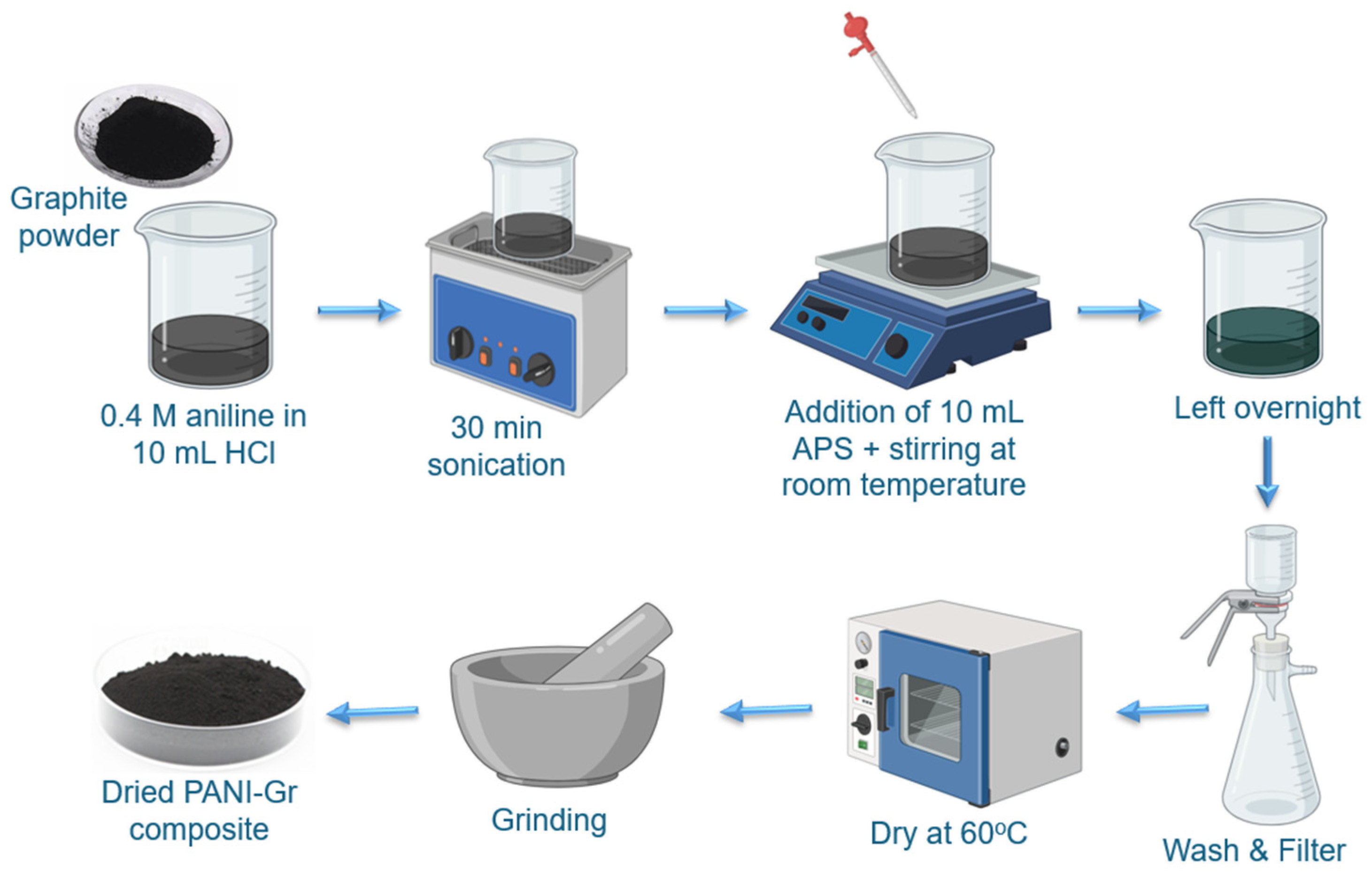
2.2. Composite Materials Preparation

Preparation of composite materials using in situ polymerization was carried out based on a reported methodology, but in the presence of graphite particles without any previous modification or surface treatment [36]. The synthesis of PANI and PANI-Gr composites were carried out at room temperature, making the method industrially viable since it requires minimal energy consumption. To prepare raw PANI, 10 mL of a solution of aniline monomer 0.4 M dissolved in HCl 1 M was mixed with 10 mL of APS 0.5 M in deionized water under continuous stirring for 30 min at room temperature. The product obtained was then kept without stirring overnight to allow a dark-green solid precipitate. Afterwards, the product was washed by using 0.2 M HCl and acetone twice and filtered using conventional lab filter paper. Finally, the product was dried firstly on a hot plate at 80 °C and finally at room temperature under reduced pressure overnight (Scheme 1). To prepare PANI-Gr composite materials, a similar procedure was followed, but the concentration of aniline monomer was increased gradually in ratios, as described in Table 1. The ratio of APS/aniline was kept at 1.25 in all the polymerization reactions, and the PANI and graphite content were determined from stoichiometric calculations.

2.3. Characterization

SEM micrographs of PANI, graphite, and composite materials were obtained using a Hitachi SU-8000 field emission scanning electron microscope (FESEM) (Hitachi High-Technologies Corporation, Tokyo, Japan). FTIR spectra was obtained using a Perkin Elmer Frontier FTIR Spectrometer (Perkin Elmer, Waltham, MA, USA). TGA analyses was carried out using a Perkin Elmer TGA 4000 (Perkin Elmer, Waltham, MA, USA) under nitrogen atmosphere at a scan rate of 20 °C/min. Specific surface area was determined using a surface area and pore size analyzer Quantachrome Model Nova 2200e (Quantachrome Instruments, Boynton Beach, FL, USA), applying the Brunauer–Emmett–Teller (BET) equation using nitrogen as adsorbate at 77 °K. In total, 300 mg of sample was previously degassed using reduced pressure at 100 °C. The measurements were performed considering 30 adsorption points and 30 desorption points using an interval from 0.005 to 0.99 of relative pressure (p/p0). Pore size distribution was calculated using the Barret Joyner and Halenda (BJH) model from the desorption data. Electrical conductivity was obtained by measuring the resistance of the composite using a two-probe method. Dried powder of the samples was pressed into pellets of 1.0 mm and 19 mm diameter, a standard DC voltage/current detector, and a two-probe electrode configuration method was used. The sample was placed between two electrodes, current was passed through the electrodes, and the resistance was measured using a two-probe digital multimeter. The average value of resistance was taken at least at seven different points, and the conductivity (σ) was calculated using Equation (1) [12].
σ = 1 R × L A
where R is the average resistance (Ω), L is the thickness (cm), and A (cm2) is the area of the sample.
Cyclic voltammetry (CV) of electrodes was obtained using a Pine Wavedriver 10 potentiostat/galvanostat (Pine Research Instrumentation, Durham, NC, USA) in a three-electrode electrochemical cell. Ag/AgCl was used as reference electrode and Pt metal as counter electrode, using 0.1 M H2SO4 as the electrolyte and a potential window from 0 to 0.6 V. Electrodes were prepared in a similar method to reference [37] using 50 mg of the active materials (raw PANI or PANI-Gr composites), which were mixed in 2.0 mL ethanol, followed by the addition of 5.0 wt. % of PAA as a binder and 2.5 wt.% of carbon black as a conductive additive. The mixture was immersed in an ultrasonic bath for 1 h to obtain a uniform dispersion of the composite sample. The mixture was then dip-coated on a fluorine-doped tin oxide (FTO) glass-coated substrate and dried at 60 °C for 12 h. The same procedure was repeated for all the composites. Specific capacitance (Cs) in F·g−1 units, energy density (E) in Wh·Kg−1 units and power density (P) in W·Kg−1 were calculated from the equations shown below [7,11,12]. The weight of active materials in the measurements were between 2.0 and 1.4 mg.
C s = j t V
E = C s × V ² 7.2
P = E × 3600 t
where j is current density (A·g−1), ∆t is discharge time (s) ∆V is potential window (V).

3. Results

Figure 1 shows the SEM micrographs of graphite, PANI, and composite materials. Graphite micrographs show irregular flakes with a length of approximately 3.0 ± 0.2 μm, whereas raw PANI tends to form polymer micron-sized agglomerates. In contrast to its individual components, PANI-Gr composite materials show a homogeneous rod/chain morphology with a diameter of approximately 150 nm and whose length depends on the aniline concentration, as is shown in Table 1. This morphology change with similar dimensions was observed previously for other PANI–graphite materials, and it was accused to the ultrasonic treatment [38]. In the case of PANI-Gr3, the rod length of the composite materials is notably larger in comparison with the other two samples. It is previously known that changes in PANI morphology are related to the pH of the medium [39] or the polymerization induction time [40]. Therefore, changes, especially on the diameter and length of the rods of PANI-Gr composite materials, can be attributed to both reasons; for one side, the role of graphite, which may enable to restrain PANI agglomerates, and on the other hand, due to a slower polymerization kinetics caused by the presence of graphite structures. The latter effect has been previously observed in the polymerization of methyl methacrylate with graphene oxide [41]. Finally, it is worth mentioning that this morphology changes from micron-size plates and agglomerates from graphite and PANI, respectively, to nano-chain composites that therefore have an increase in the surface area. Table 1 shows the specific BET surface area obtained for graphite, PANI, and composite materials. Composite materials showed a slight increase in the specific surface area compared to raw synthesized PANI, but lower than other PANI values reported [42,43]. However, it is worth mentioning that other authors like El-Shazly et al. indicate that the specific surface area of PANI–clay nanocomposites is lower than PANI due to the blocking of the active sites of the material because of the filler [44]. In our work, we consider that this small increase is due to the change in morphology of PANI nanocomposites.
Table 1. PANI-Graphite composite materials prepared.
SampleAniline: Graphite Weight RatioPANI Content (wt. %)Rod Length
(nm)
Rod Diameter (nm)Surface Area (m2/g)Pore Volume(cm3/g)
Graphite-0--4.420.009
PANI-100--9.86 *0.083 *
PANI-Gr11:150546 ± 136136 ± 4011.370.016
PANI-Gr22:166383 ± 150148 ± 2311.870.011
PANI-Gr33:175973 ± 276178 ± 916.680.014
* Obtained from previously published results [45].
Figure 2 shows the FTIR spectra of the composite materials obtained. Raw PANI and graphite are represented for comparison. PANI bands, which appear at 1487 and 1562 cm−1, are attributed to the C=C stretching benzenoid and quinoid ring deformation, respectively [32,46,47]. The band at 1110 cm−1, which also appears in the composite material, is attributed to the electron delocalization in the PANI salts [48]. The peak that appears at 1300 cm−1 corresponds to C-N stretching vibration [32,46]. Raw graphite and graphite composite materials present a band in 1220 cm−1, which corresponds to the C-C bond deformation [49], and the band at 1020 cm−1 is assigned the C-O-C stretching [50] due to the oxidation of graphite by the action of the APS oxidant during the polymerization reaction.
The thermal stability of raw components and composite materials was evaluated through TGA, shown in Figure 3. Figure 3a shows the TGA curves, and Figure 3b,c shows the weight derivative for the raw and composite materials prepared. Pure graphite presents thermal stability and a minimal weight loss up to 700 °C. After that temperature, graphite showed a dramatic decrease and decomposition that, according to the literature, is dependent on particle size [51]. This decomposition is attributed to the highly energetic degradation process of the 3D carbon network of graphite, which consists of numerous stacked graphene layers and the additional energy to break Van der Waal forces [52]. However, graphite still presents less than 24% of weight up to 800 °C. PANI presents three decomposition processes. The first step below 150 °C is attributed to the loss of residual moisture and free undoped HCl present; the second decomposition process between 150 °C and 350 °C is due to the doped HCl decomposition [53]; and the third step above 400 °C is attributed to the polymer backbone decomposition [54]. The indicated weight loss intervals coincide with the curves of the normalized derivative weight losses shown in Figure 3b,c. PANI-Gr1 and PANI-Gr3, with higher graphite content, present improved thermal stability compared to pure PANI, as can be seen in the derivative of weight loss where the highest rate of PANI decomposition occurs at 260 °C (doped HCl decomposition). PANI-Gr2 shows a different decomposition curve compared with the other two composites. This behavior above 300 °C is due to the less intercalation of the PANI inside the graphite sheets, achieving less exfoliation of the sheets. The peak of the derivative of weight loss (Tmax) of the PANI-Gr2 appears at 230 °C, a lower temperature value if we compare it to raw PANI or the other two composites. This behavior may also be due to the lower doping ratio in this composite, and a probably lower molecular weight if we compare it to the original PANI or that obtained for the other two composites. Composites graphs recorded the highest Tmax range (716–726 °C), and can be linked to their respective carbon building blocks involved in the bonding and structural framework, showing that all these materials were burnt in nitrogen atmosphere before 800 °C, leaving less than 10% of residue behind, and suggesting the high purity of the graphite.

Electrochemical Studies of PANI-Gr Composites

Capacitive performances of PANI and PANI-Gr composite materials have been investigated using cyclic voltammetry (CV) and galvanometry charge–discharge (GCD) methods in a three-electrode system. FTO glass (current collector), coated with the polymer or composite was used as working electrode, Pt as a counter electrode and Ag/AgCl as reference electrode using 0.1 M H2SO4 as electrolyte. Figure 4a shows the CV curves for the electrodes performed within a potential window of 0–600 mV vs. Ag/AgCl at a scan rate of 20 mV·s−1. The enclosed area of CV curves in PANI and the composites by exception of PANI-Gr3 are quite similar at 20 mV·s−1, indicating a comparable charge storage capacity. Meanwhile, PANI-Gr3 showed poor charge storage capacity. Figure 4b shows the CV curve at a sweep rate of 5 mV·s−1. The characteristic redox peaks observed around 400 mV was due to the pseudocapacitive nature of PANI [55]. Moreover, at 5 mV·s−1, the shape of the CV curves appears more rectangular, and it is clear that the mechanism of charge storage of the PANI-graphite composite is based on electrostatic adsorption of electrolyte ions at the electrode/electrolyte interface. This fact is explained by the double-layer capacitive behavior of graphite and the surface redox reaction, which is mostly of PANI [56]. Figure 4c shows the plot of specific capacitance versus sweep rate, specific capacitance increases with a decrease in sweep rate for both PANI and PANI-Gr1. This is because electrostatic adsorption and desorption of electrolyte ions at the electrode–electrolyte interfere has sufficient time to take place, but the opposite was the case when the sweep rate increases [57]. Nevertheless, a decrease in electrochemical reversibility occurs at a lower sweep rate, which resulted from the slower galvano-dynamic response. This phenomenon occurs because the ion diffusion of the electrode is limited, whereas the capacitance depends firmly on the redox reactions than double layer [58]. The galvano-dynamic response can be improved by modifying the graphite surface to create a pore structure on the graphite surface and increase the specific surface area [45]; these will result in increased ion adsorption at the electrode/electrolyte interface.
A galvanostatic charge–discharge (GCD) test was used to further study the electrochemical performance of the PANI-Gr1 composite at different current densities, 0.5, 1.0, 2.0, 3.0, and 4.0 A·g−1 and the result was then compared with PANI. Figure 5 shows the GCD curves performed at different current densities within a potential window of 0–600 mV. Quasi-triangular shape observed in the GCD curve is an indication that the overall capacitance values in the PANI-Gr1 composite are the combined features of both the electrical double layer and pseudo-capacitance. The value of the specific capacitance calculated from the GCD measurement for PANI-Gr1 was 238 F·g−1 at 0.5 A·g−1 of current density. Figure 5c shows the voltage drop observed at different current densities. Voltage drops observed at the initial stage of discharge on the GCD curve, could be caused by the internal resistance of active electrode materials [59]. From Figure 5c, the voltage drops observed for PANI and PANI-Gr1 are 0.0595 V and 0.0485 V at a low current density of 0.5 A·g−1, and 0.485 V and 0.399 V at 4.0 A·g−1, respectively. The voltage drop of the PANI-Gr1 composite is lower than pure PANI in all the current densities measured. The decrease in voltage drop observed in the PANI-Gr1 composite is accused to the low electrical resistance from the graphite. Nevertheless, there is a pronounced decrease in the capacitive properties with the current density. This could be due to the high ohmic polarization caused by the intrinsic resistance of the electrode material. This phenomenon is derived from the resistance of the electrolyte solution and the contact resistance at the interface between the electrode material and the current collector [60]. This can be reduced by improving the conductivity of the electrode material, eliminate the binder used or changing the current collector. The measured electrical conductivity of PANI-Gr1 was 1.94 × 10⁻³ S·cm−1, which is about 28% higher compared to PANI, which was 1.40 × 10⁻³ S·cm−1, indicating that the presence of graphite in the PANI matrix leads to improved electrical conductivity. The improvement in the electrical conductivity could be attributed to an effective electron delocalization in the PANI structure and that graphite works as a conductive bridge between the PANI-conducting domains [61]. Proper dispersion of graphite particles into the PANI matrix, coupled with its high specific surface area, can be beneficial factors for the improvement observed in the electrical conductivity and hence the electrochemical performance of the composite [62].
The specific capacitance obtained at 0.5 A·g−1 of current density for PANI-Gr1 was 238 F·g−1 which leads to an energy and power densities of 12 Wh·Kg−1 and 150 W·Kg−1, respectively. These values are lower than those of PANI which were 292 F·g−1, 15 Wh·Kg−1, and 150 Wh·Kg−1. These values make sense as pseudocapacitive effect of PANI leads to higher energy density. However, this trend changes at higher current densities. Figure 5d shows the variation of specific capacitance with respect to the current density. Specific capacitance is seen to decrease as the current density increases, and a lower specific capacity at higher current density is related to higher ion diffusion resistance into the electrode [63]. This has the disadvantage of having a restriction on the charge storage to mere surface of the composite, which could lead to inefficient use of the active material. The charge storage capacity of the electrode can also be affected by the slow response of the active materials at higher current densities [58,64]. At a current density of 3.0 A·g−1, both PANI and PANI-Gr1 showed a specific capacitance of 105 F·g−1. Meanwhile, at a current density of 4.0 A·g−1, the PANI-Gr1 composite showed a value of 60 F·g−1 and an energy density of 3 Wh·kg−1 compared to 47 F·g−1 and 2.3 Wh·kg−1 obtained for PANI. Therefore, an increase of 30% in energy density can be observed because of the presence of graphite in the composite material.
Also, in the case of the PANI-Gr1 composite, minimal diffusion resistance was observed at a current density of 4.0 A·g−1 as the specific capacity of the PANI-Gr1 began to outperform that of pure PANI, which gives room for charge storage at maximum. The energy and power density values reported in this work for both the pure PANI and the composite are comparable to the values obtained for PANI and composites prepared from PANI and carbon materials from other authors, as shown in Table 2. Moreover, results show that our energy density is within the range of commercial supercapacitors [65]. It is worth noting that our values were obtained with an electrolyte, which has ten times less acid concentration, making this method a greener approach. To demonstrate that the concentration of the electrolyte has a minimal effect in our results, we performed a CV analysis of the PANI-Gr1 with 0.1 M and 1.0 M electrolyte concentration (Figure S1). We observed minimal changes in the curve, indicating a similar charge storage and capacitive behavior. In addition to this, it is relevant to highlight again that the graphite was used as provided without any previous treatment, avoiding the use of acids for exfoliation, heat, or hydrothermal treatments, or more sophisticated methods like laser or atomic layer deposition, to improve the electrochemical performance of the material. These factors endow this composite preparation approach with the advantages of being a simple, straightforward, and sustainable method.

4. Conclusions

PANI–graphite composite materials were prepared using an in situ polymerization reaction of an aniline monomer using different graphite content. A change in the morphology from granular to nano-chain particles was observed and credited to the previous exfoliation of graphite, which acts as a template in the formation of the composite materials, with different dimensions depending on the graphite content. An improvement in thermal stability and surface area compared to pure PANI was observed with the addition of graphite as conductive filler without any previous treatment prior to polymerization. At a current density of 4.0 A·g−1, the PANI-Gr1 composite shows 30% higher energy density than raw PANI, results due to an improvement in electrical conductivity, morphology, and surface area of the composite materials. Materials prepared using in situ technology showed interesting properties towards a new generation of scalable and reasonable-cost energy storage devices.
The need for continuous search for cheaper energy keeps increasing, and the full potential of CPs for energy storage applications is yet to be explored. Therefore, intensified research efforts are essential to combine the electrical conductivity and fast redox kinetics in the various CPs such as PANI and its derivatives. Carbon forms from different sources, especially biomass-based which are cheap, abundant, eco-friendly, and have the potential to attain high specific surface area, will be of great benefit for the in situ preparation of composite materials for cheap and efficient energy application. Another interesting area of study of these methodologies are binder-free electrodes or in situ conductive binders, which will enable a high conductivity and electrochemical performance of these and similar composites for supercapacitors applications.

Supplementary Materials

The following supporting information can be downloaded at: https://www.mdpi.com/article/10.3390/jcs8060200/s1, Figure S1. Comparison of the electrolyte concentration of H2SO4 electrolyte on the electrochemical performance of PANI–Gr1 composite.

Author Contributions

Conceptualization, F.J.G.; Methodology, F.J.G.; validation, S.E.K. and O.S.A.; formal analysis, F.J.G., M.A.G.-L. and S.E.K.; investigation, F.J.G., S.E.K. and O.S.A.; resources, F.J.G. and M.A.G.-L.; data curation; S.E.K. and M.A.G.-L.; writing—original draft preparation, F.J.G. and S.E.K.; writing—review and editing, F.JG., M.H., M.T.R. and M.A.G.-L.; visualization, F.J.G. and S.E.K.; supervision, F.J.G.; project administration, F.J.G.; funding acquisition, F.J.G. and M.H. All authors have read and agreed to the published version of the manuscript.

Funding

The authors gratefully acknowledge the financial support of CONAHCYT: CVU 1244598; and CVU 1245789S projects. E.K. and O.S.A. thanks CONAHCYT for the scholarship granted for their PhD studies.

Data Availability Statement

The original contributions presented in the study are included in the article/Supplementary Materials, further inquiries can be directed to the corresponding authors.

Acknowledgments

The authors acknowledge to Jorge Cañas Montoya his assistance with SEM micrographs, to Cynthia Luévano Martínez for her technical assistance with TGA and FTIR analyses and to M.C. José Martín Bass López for the surface area and pore size analysis.

Conflicts of Interest

The authors declare no conflict of interest.

References

  1. Simon, P.; Gogotsi, Y. Perspectives for electrochemical capacitors and related devices. Nat. Mater. 2020, 19, 1151–1163. [Google Scholar] [CrossRef]
  2. Miller, E.E.; Hua, Y.; Tezel, F.H. Materials for energy storage: Review of electrode materials and methods of increasing capacitance for supercapacitors. J. Energy Storage 2018, 20, 30–40. [Google Scholar] [CrossRef]
  3. Gan, Y.X. Activated Carbon from Biomass Sustainable Sources. C 2021, 7, 39. [Google Scholar] [CrossRef]
  4. Zhou, M.; Yan, S.-X.; Wang, Q.; Tan, M.-X.; Wang, D.-Y.; Yu, Z.-Q.; Luo, S.-H.; Zhang, Y.-H.; Liu, X. Walnut Septum-Derived Hierarchical Porous Carbon for Ultra-High-Performance Supercapacitors. Rare Met. 2022, 41, 2280–2291. [Google Scholar] [CrossRef]
  5. Kayode, S.E.; González, F.J. Treatment of Biowaste for Electrodes in Energy Storage Applications: A Brief Review. J. Compos. Sci. 2023, 7, 127. [Google Scholar] [CrossRef]
  6. Qing, Y.; Jiang, Y.; Lin, H.; Wang, L.; Liu, A.; Cao, Y.; Sheng, R.; Guo, Y.; Fan, C.; Zhang, S.; et al. Boosting the supercapacitor performance of activated carbon by constructing overall conductive networks using graphene quantum dots. J. Mater. Chem. A 2019, 7, 6021–6027. [Google Scholar] [CrossRef]
  7. Shokry, A.; Karim, M.; Khalil, M.; Ebrahim, S.; El Nady, J. Supercapacitor Based on Polymeric Binary Composite of Polythiophene and Single-Walled Carbon Nanotubes. Sci. Rep. 2022, 12, 11278. [Google Scholar] [CrossRef]
  8. Xie, P.; Yuan, W.; Liu, X.; Peng, Y.; Yin, Y.; Li, Y.; Wu, Z. Advanced carbon nanomaterials for state-of-the-art flexible supercapacitors. Energy Storage Mater. 2021, 36, 56–76. [Google Scholar] [CrossRef]
  9. Olabi, A.G.; Abbas, Q.; Abdelkareem, M.A.; Alami, A.H.; Mirzaeian, M.; Sayed, E.T. Carbon-Based Materials for Supercapacitors: Recent Progress, Challenges and Barriers. Batteries 2023, 9, 19. [Google Scholar] [CrossRef]
  10. Majumdar, D.; Maiyalagan, T.; Jiang, Z. Recent Progress in Ruthenium Oxide-Based Composites for Supercapacitor Applications. ChemElectroChem 2019, 6, 4343–4372. [Google Scholar] [CrossRef]
  11. Ahmad, R.; Shah, M.A. Hydrothermally Synthesised Nickel Oxide Nanostructures on Nickel Foam and Nickel Foil for Supercapacitor Application. Ceram. Int. 2023, 49, 6470–6478. [Google Scholar] [CrossRef]
  12. Radhakanth, S.; Singhal, R. In–Situ Synthesis of MnO Dispersed Carbon Nanofibers as Binder-Free Electrodes for High-Performance Supercapacitors. Chem. Eng. Sci. 2023, 265, 118224. [Google Scholar] [CrossRef]
  13. Fan, Y.; Chen, H.; Li, Y.; Cui, D.; Fan, Z.; Xue, C. PANI-Co3O4 with Excellent Specific Capacitance as an Electrode for Supercapacitors. Ceram. Int. 2021, 47, 8433–8440. [Google Scholar] [CrossRef]
  14. Yuan, K.; Gao, T.-J.; Yang, Y.; Luo, W.; Li, S.; Zhang, C.-Y.; Xu, J.-X.; Li, N.; Zhu, Y.-R. Template Sacrificial Controlled Synthesis of Hierarchical Nanoporous Carbon@NiCo2S4 Microspheres for High-Performance Hybrid Supercapacitors. Rare Met. 2023, 42, 2643–2657. [Google Scholar] [CrossRef]
  15. Zhang, Z.; Liao, M.; Lou, H.; Hu, Y.; Sun, X.; Peng, H. Conjugated Polymers for Flexible Energy Harvesting and Storage. Adv. Mater. 2018, 30, 1704261. [Google Scholar] [CrossRef]
  16. Snook, G.A.; Kao, P.; Best, A.S. Conducting-polymer-based supercapacitor devices and electrodes. J. Power Sources 2011, 196, 1–12. [Google Scholar] [CrossRef]
  17. Peng, C.; Zhang, S.; Jewell, D.; Chen, G.Z. Carbon nanotube and conducting polymer composites for supercapacitors. Prog. Nat. Sci. 2008, 18, 777–788. [Google Scholar] [CrossRef]
  18. Lota, K.; Khomenko, V.; Frackowiak, E. Capacitance properties of poly(3,4-ethylenedioxythiophene)/carbon nanotubes composites. J. Phys. Chem. Solids 2004, 65, 295–301. [Google Scholar] [CrossRef]
  19. Li, H.; Wang, J.; Chu, Q.; Wang, Z.; Zhang, F.; Wang, S. Theoretical and experimental specific capacitance of polyaniline in sulfuric acid. J. Power Sources 2009, 190, 578–586. [Google Scholar] [CrossRef]
  20. Hassan, H.; Iqbal, M.W.; Afzal, A.M.; Asghar, M.; Aftab, S. Enhanced the Performance of Zinc Strontium Sulfide-Based Supercapattery Device with the Polyaniline Doped Activated Carbon. J. Solid State Electrochem. 2023, 27, 125–137. [Google Scholar] [CrossRef]
  21. Ajay, K.M.; Dinesh, M.N.; Byatarayappa, G.; Radhika, M.G.; Kathyayini, N.; Vijeth, H. Electrochemical Investigations on Low Cost KOH Activated Carbon Derived from Orange-Peel and Polyaniline for Hybrid Supercapacitors. Inorg. Chem. Commun. 2021, 127, 108523. [Google Scholar] [CrossRef]
  22. Akbar, A.R.; Saleem, A.; Rauf, A.; Iqbal, R.; Tahir, M.; Peng, G.; Khan, A.S.; Hussain, A.; Ahmad, M.; Akhtar, M.; et al. Integrated MnO2/PEDOT Composite on Carbon Cloth for Advanced Electrochemical Energy Storage Asymmetric Supercapacitors. J. Power Sources 2023, 579, 233181. [Google Scholar] [CrossRef]
  23. Himadri Reddy, P.C.; Amalraj, J.; Ranganatha, S.; Patil, S.S.; Chandrasekaran, S. A Review on Effect of Conducting Polymers on Carbon-Based Electrode Materials for Electrochemical Supercapacitors. Synth. Met. 2023, 298, 117447. [Google Scholar] [CrossRef]
  24. Javed, M.S.; Khan, A.J.; Hanif, M.; Nazir, M.T.; Hussain, S.; Saleem, M.; Raza, R.; Yun, S.; Liu, Z. Engineering the Performance of Negative Electrode for Supercapacitor by Polyaniline Coated Fe3O4 Nanoparticles Enables High Stability up to 25,000 Cycles. Int. J. Hydrogen Energy 2021, 46, 9976–9987. [Google Scholar] [CrossRef]
  25. González, F.J.; Montesinos, A.; Araujo-Morera, J.; Verdejo, R.; Hoyos, M. ‘In-Situ’ Preparation of Carbonaceous Conductive Composite Materials Based on PEDOT and Biowaste for Flexible Pseudocapacitor Application. J. Compos. Sci. 2020, 4, 87. [Google Scholar] [CrossRef]
  26. Ates, M.; Serin, M.A.; Calisskan, S. Electrochemical supercapacitors of PANI/MWCNT, PEDOT/MWCNT and PANI-co-EDOT/MWCNT nanocomposites. Polym. Bull. 2019, 76, 3207–3231. [Google Scholar] [CrossRef]
  27. . Sun, M.; Wang, G.; Yang, C.; Jiang, H.; Li, C. A graphene/carbon nanotube@π-conjugated polymer nanocomposite for high-performance organic supercapacitor electrodes. J. Mater. Chem. A 2015, 3, 3880–3890. [Google Scholar] [CrossRef]
  28. Maddu, A.; Nugroho, R.A.; Rustami, E.; Arjo, S.; Hidayat, M. Synthesis of Graphene/Polyaniline Nanocomposite for Supercapacitor Electrodes. J. Phys. Conf. Ser. 2019, 1171, 12043. [Google Scholar] [CrossRef]
  29. Qi, W.; Lv, R.; Na, B.; Liu, H.; He, Y.; Yu, N. Nanocellulose-Assisted Growth of Manganese Dioxide on Thin Graphite Papers for High-Performance Supercapacitor Electrodes. ACS Sustain. Chem. Eng. 2018, 6, 4739–4745. [Google Scholar] [CrossRef]
  30. Sun, X.-T.; Wan, Y.; Wang, B.; Xu, Q.; Teng, X.-L.; Liu, H.-Y.; Wang, Y.-J.; Guo, S.-W.; Wu, C.-H.; Hu, H.; et al. Laser Irradiation of Graphite Foils as Robust Current Collectors for High-Mass Loaded Electrodes of Supercapacitors. Rare Met. 2022, 41, 4094–4103. [Google Scholar] [CrossRef]
  31. Sharma, K.; Pareek, K.; Rohan, R.; Kumar, P. Flexible supercapacitor based on three-dimensional cellulose/graphite/polyaniline composite. Int. J. Energy Res. 2019, 43, 604–611. [Google Scholar] [CrossRef]
  32. Zhou, H.; Zhang, W.; Zhi, X.; Zhai, H.J. Remarkably enhanced performances of polyaniline/electrochemically surface-treated graphite electrodes with optimal charge transfer pathways for flexible supercapacitor application. J. Power Sources 2018, 402, 311–319. [Google Scholar] [CrossRef]
  33. Yao, B.; Yuan, L.; Xiao, X.; Zhang, J.; Qi, Y.; Zhou, J.; Zhou, J.; Hu, B.; Chen, W. Paper-based solid-state supercapacitors with pencil-drawing graphite/polyaniline networks hybrid electrodes. Nano Energy 2013, 2, 1071–1078. [Google Scholar] [CrossRef]
  34. Melih, B.A.; Emirhan, A.; Ozge, G.; Semih, G.; Sahin, Y. Construction of Phthalocyanine-Titanium Dioxide/Graphene/Polyaniline Composite Electrodes by Electrochemical Method for Supercapacitor Applications. ECS J. Solid State Sci. Technol. 2023, 12, 031008. [Google Scholar] [CrossRef]
  35. González, F.; Tiemblo, P.; Hoyos, M. In-Situ Approaches for the Preparation of Polythiophene-Derivative Cellulose Composites with High Flexibility and Conductivity. Appl. Sci. 2019, 9, 3371. [Google Scholar] [CrossRef]
  36. Stejskal, J.; Gilbert, R.G. Polyaniline. Preparation of a conducting polymer (IUPAC technical report). Pure Appl. Chem. 2002, 74, 857–867. [Google Scholar] [CrossRef]
  37. Patil, D.S.; Pawar, S.A.; Devan, R.S.; Gang, M.G.; Ma, Y.R.; Kim, J.H.; Patil, P.S. Electrochemical supercapacitor electrode material based on polyacrylic acid/polypyrrole/silver composite. Electrochim. Acta 2013, 105, 569–577. [Google Scholar] [CrossRef]
  38. Mo, Z.; Shi, H.; Chen, H.; Niu, G.; Zhao, Z.; Wu, Y. Synthesis of graphite nanosheets/polyaniline nanorods composites with ultrasonic and conductivity. J. Appl. Polym. Sci. 2009, 112, 573–578. [Google Scholar] [CrossRef]
  39. Wang, J.; Wang, J.; Yang, Z.; Wang, Z.; Zhang, F.; Wang, S. A novel strategy for the synthesis of polyaniline nanostructures with controlled morphology. React. Funct. Polym. 2008, 68, 1435–1440. [Google Scholar] [CrossRef]
  40. Wang, J.; Wang, J.; Zhang, X.; Wang, Z. Assembly of polyaniline nanostructures. Macromol. Rapid Commun. 2007, 28, 84–87. [Google Scholar] [CrossRef]
  41. Tsagkalias, I.S.; Manios, T.K.; Achilias, D.S. Effect of graphene oxide on the reaction kinetics of methyl methacrylate in situ radical polymerization via the bulk or solution technique. Polymers 2017, 9, 432. [Google Scholar] [CrossRef] [PubMed]
  42. Xu, H.; Li, X.; Wang, G. Polyaniline Nanofibers with a High Specific Surface Area and an Improved Pore Structure for Supercapacitors. J. Power Sources 2015, 294, 16–21. [Google Scholar] [CrossRef]
  43. Ayuningsih, A.; Budi, S.; Paristiowati, M.; Fahdiran, R.; Handoko, E.; Sugihartono, I. Aniline Concentration-Dependent Surface Area of Emeraldine Salt Polyaniline. IOP Conf. Ser. Mater. Sci. Eng. 2021, 1098, 062068. [Google Scholar] [CrossRef]
  44. El-Shazly, A.H.; Elkady, M.; Abdelraheem, A. Investigating the Adsorption Behavior of Polyaniline and Its Clay Nanocomposite towards Ammonia Gas. Polymers 2022, 14, 4533. [Google Scholar] [CrossRef] [PubMed]
  45. Arvizu, M.A.; González, F.J.; Romero-Galarza, A.; Rodríguez-Varela, F.J.; Garcia, C.R.; Garcia-Lobato, M.A. Symmetric Supercapacitors of PANI Coated RuO2 /TiO2 Macroporous Structures Prepared by Electrostatic Spray Deposition. J. Electrochem. Soc. 2022, 169, 020564. [Google Scholar] [CrossRef]
  46. Li, N.; Hou, Z.; Liang, S.; Cao, Y.; Liu, H.; Hua, W.; Wei, C.; Kang, F.; Wang, J.-G. Highly Flexible MnO2@polyaniline Core-Shell Nanowire Film toward Substantially Expedited Zinc Energy Storage. Chem. Eng. J. 2023, 452, 139408. [Google Scholar] [CrossRef]
  47. Yelil Arasi, A.; Juliet Latha Jeyakumari, J.; Sundaresan, B.; Dhanalakshmi, V.; Anbarasan, R. The structural properties of Poly(aniline)-Analysis via FTIR spectroscopy. Spectrochim. Acta Part A Mol. Biomol. Spectrosc. 2009, 74, 1229–1234. [Google Scholar] [CrossRef] [PubMed]
  48. Yang, J.; Ding, Y.; Zhang, J. Uniform rice-like nanostructured polyanilines with highly crystallinity prepared in dodecylbenzene sulfonic acid micelles. Mater. Chem. Phys. 2008, 112, 322–324. [Google Scholar] [CrossRef]
  49. Nikzad, L.; Alibeigi, S.; Vaezi, M.R.; Yazdani, B.; Rahimipour, M.R. Synthesis of a graphite-polyaniline nanocomposite and evaluation of its electrochemical properties. Chem. Eng. Technol. 2009, 32, 861–866. [Google Scholar] [CrossRef]
  50. Shao, L.; Chang, X.; Zhang, Y.; Huang, Y.; Yao, Y.; Guo, Z. Graphene oxide cross-linked chitosan nanocomposite membrane. Appl. Surf. Sci. 2013, 280, 989–992. [Google Scholar] [CrossRef]
  51. Zaghib, K.; Song, X.; Kinoshita, K. Thermal Analysis of the Oxidation of Natural Graphite: Isothermal Kinetic Studies. Thermochim. Acta 2001, 371, 57–64. [Google Scholar] [CrossRef]
  52. Farivar, F.; Yap, P.L.; Karunagaran, R.U.; Losic, D. Thermogravimetric Analysis (TGA) of Graphene Materials: Effect of Particle Size of Graphene, Graphene Oxide and Graphite on Thermal Parameters. J. Carbon Res. 2021, 7, 41. [Google Scholar] [CrossRef]
  53. Sui, X.; Chu, Y.; Xing, S.; Yu, M.; Liu, C. Self-organization of spherical PANI/TiO2 nanocomposites in reverse micelles. Colloids Surf. A Physicochem. Eng. Asp. 2004, 251, 103–107. [Google Scholar] [CrossRef]
  54. Kumar, A.; Kumar, A.; Mudila, H.; Awasthi, K.; Kumar, V. Synthesis and thermal analysis of polyaniline (PANI). J. Phys. Conf. Ser. 2020, 1531, 012108. [Google Scholar] [CrossRef]
  55. Du, X.; Xu, Y.; Xiong, L.; Bai, Y.; Zhu, J.; Mao, S. Polyaniline with high crystallinity degree: Synthesis, structure, and electrochemical properties. J. Appl. Polym. Sci. 2014, 131, 40827. [Google Scholar] [CrossRef]
  56. Du, J.; Li, Y.; Zhong, Q.; Yang, J.; Xiao, J.; Chen, D.; Li, W. Boosting the Utilization and Electrochemical Performances of Polyaniline by Forming a Binder-Free Nanoscale Coaxially Coated Polyaniline/Carbon Nanotube/Carbon Fiber Paper Hierarchical 3D Microstructure Composite as a Supercapacitor Electrode. ACS Omega 2020, 5, 22119–22130. [Google Scholar] [CrossRef] [PubMed]
  57. Bhoyate, S.; Ranaweera, C.K.; Zhang, C.; Morey, T.; Hyatt, M.; Kahol, P.K.; Gupta, R.K. Eco-Friendly and High Performance Supercapacitors for Elevated Temperature Applications Using Recycled Tea Leaves. Glob. Chall. 2017, 1, 1700063. [Google Scholar] [CrossRef] [PubMed]
  58. Jeyaranjan, A.; Sakthivel, T.S.; Neal, C.J.; Seal, S. Scalable ternary hierarchical microspheres composed of PANI/ rGO/CeO2 for high performance supercapacitor applications. Carbon 2019, 151, 192–202. [Google Scholar] [CrossRef]
  59. Pan, C.; Gu, H.; Dong, L. Synthesis and electrochemical performance of polyaniline @MnO2/graphene ternary composites for electrochemical supercapacitors. J. Power Sources 2016, 303, 175–181. [Google Scholar] [CrossRef]
  60. Zhang, D.; Yang, B.; She, W.; Gao, S.; Wang, J.; Wang, Y.; Wang, K.; Li, H.; Han, L. Simultaneously Achieving High Energy and Power Density for Ultrafast-Charging Supercapacitor Built by a Semi-Graphitic Hierarchical Porous Carbon Nanosheet and a High-Voltage Alkaline Aqueous Electrolyte. J. Power Sources 2021, 506, 230103. [Google Scholar] [CrossRef]
  61. Wu, T.-M.; Lin, Y.-W.; Liao, C.-S. Preparation and characterization of polyaniline/multi-walled carbon nanotube composites. Carbon 2005, 43, 734–740. [Google Scholar] [CrossRef]
  62. Elnaggar, E.M.; Kabel, K.I.; Farag, A.A.; Al-Gamal, A.G. Comparative study on doping of polyaniline with graphene and multi-walled carbon nanotubes. J. Nanostruct. Chem. 2017, 7, 75–83. [Google Scholar] [CrossRef]
  63. Kim, J.W.; Augustyn, V.; Dunn, B. The Effect of Crystallinity on the Rapid Pseudocapacitive Response of Nb2O5. Adv. Energy Mater. 2012, 2, 141–148. [Google Scholar] [CrossRef]
  64. Wang, J.; Polleux, J.; Lim, J.; Dunn, B. Pseudocapacitive Contributions to Electrochemical Energy Storage in TiO2 (Anatase) Nanoparticles. J. Phys. Chem. C 2007, 111, 14925–14931. [Google Scholar] [CrossRef]
  65. Sirimanne, D.C.U.; Kularatna, N.; Arawwawala, N. Electrical Performance of Current Commercial Supercapacitors and Their Future Applications. Electronics 2023, 12, 2465. [Google Scholar] [CrossRef]
  66. Dhawale, D.S.; Vinu, A.; Lokhande, C.D. Stable nanostructured polyaniline electrode for supercapacitor application. Electrochim. Acta 2011, 56, 9482–9487. [Google Scholar] [CrossRef]
  67. Zhang, L.L.; Li, S.; Zhang, J.; Guo, P.; Zheng, J.; Zhao, X.S. Enhancement of Electrochemical Performance of Macroporous Carbon by Surface Coating of Polyaniline. Chem. Mater. 2010, 22, 1195–1202. [Google Scholar] [CrossRef]
  68. Zhao, Z.; Xie, Y. Enhanced electrochemical performance of carbon quantum dots-polyaniline hybrid. J. Power Sources 2017, 337, 54–64. [Google Scholar] [CrossRef]
  69. Li, L.; Raji, A.-R.O.; Fei, H.; Yang, Y.; Samuel, E.L.G.; Tour, J.M. Nanocomposite of Polyaniline Nanorods Grown on Graphene Nanoribbons for Highly Capacitive Pseudocapacitors. ACS Appl. Mater. Interfaces 2013, 5, 6622–6627. [Google Scholar] [CrossRef]
  70. Li, J.; Ren, Y.; Ren, Z.; Wang, S.; Qiu, Y.; Yu, J. Aligned polyaniline nanowires grown on the internal surface of macroporous carbon for supercapacitors. J. Mater. Chem. A 2015, 3, 23307–23315. [Google Scholar] [CrossRef]
  71. Zhang, X.; Lin, Q.; Zhang, X.; Peng, K. A novel 3D conductive network-based polyaniline/graphitic mesoporous carbon composite electrode with excellent electrochemical performance. J. Power Sources 2018, 401, 278–286. [Google Scholar] [CrossRef]
Scheme 1. Preparation of PANI-Graphite composites.
Jcs 08 00200 sch001
Figure 1. SEM micrographs of graphite, PANI, and PANI-Gr composite materials. Magnification: 20,000×.
Jcs 08 00200 g001
Figure 2. FTIR spectra of graphite, PANI, and PANI-Gr composite materials.
Jcs 08 00200 g002
Figure 3. (a) TGA curves and (b,c) normalized derivative weight loss curves of PANI, graphite, and PANI-Gr composite materials.
Jcs 08 00200 g003
Figure 4. (a) CV curves of polyaniline–graphite composite performed at 20 mV·s−1; (b) CV curves of PANI and PANI–Gr1 at 5 mV·s−1; (c) plot of specific capacitance vs. the sweep rate.
Jcs 08 00200 g004
Figure 5. Electrochemical performance of PANI and PANI-Gr1 electrodes. (a) GCD curve of PANI; (b) GCD curve of PANI-Gr1; (c) voltage drop at different current densities; and (d) specific capacitance at different current densities.
Jcs 08 00200 g005
Table 2. Electrochemical performance of PANI/Gr and PANI/nanocarbon composite materials.
SamplePotential Range (V)ElectrolyteCurrent Density (A·g−1)Specific Energy (Wh·kg−1)Specific Power (W·kg−1)Reference
PANI−0.1–0.81 M H2SO41.0 mA.cm−29.8896[66]
PANI-DOMC−0.2–0.82 M H2SO40.549182[67]
CQDs-PANI/CFs0–0.61 M H2SO41.036.9300[68]
PANI/GNRs0–0.81 M H2SO40.257.563149[69]
PANI/MC0–1.01 M H2SO41.019500[70]
PANI/GMC−0.2–0.81 M H2SO41.024.64250[71]
PANI-Gr0–0.60.1 M H2SO40.512150This work
Disclaimer/Publisher’s Note: The statements, opinions and data contained in all publications are solely those of the individual author(s) and contributor(s) and not of MDPI and/or the editor(s). MDPI and/or the editor(s) disclaim responsibility for any injury to people or property resulting from any ideas, methods, instructions or products referred to in the content.

