Abstract
In this study, micro-scale numerical simulations were performed to evaluate the residual strength of carbon fiber-reinforced polymers (CFRPs) subjected to cyclic transverse and out-of-plane shear loading fatigue. The simulations utilized a finite element method, incorporating an entropy-based damage criterion for the matrix resin. This method aimed to link entropy generation to strength degradation, with the parameter determined as a function of entropy. Cyclic tensile and shear analyses were conducted to correlate residual strength with entropy accumulation, establishing a linear relationship for . The results demonstrated meso-scale strength degradation based on micro-scale numerical simulations. Material constants for the epoxy resin matrix were determined through creep and tensile tests, and a generalized Maxwell model with 15 elements was used to represent viscoelastic behavior. Numerical simulations employed the Abaqus/Standard 2020 software, with the epoxy resin matrix behavior implemented via a UMAT subroutine. The analysis revealed a linear relationship between entropy and residual strength for both cyclic tensile and out-of-plane shear loading. This approach enhances experimental insights with numerical predictions, offering a comprehensive understanding of CFRP strength degradation under fatigue loading. This study represents the first numerical approach to link the entropy of the matrix resin at the micro-scale with macro-scale residual strength in CFRP, providing a novel and comprehensive framework for understanding and predicting strength degradation under cyclic loading.
1. Introduction
Carbon fiber-reinforced polymers (CFRPs) are widely used in the aerospace industry due to their excellent mechanical properties. Understanding their durability under long-term use is crucial; however, the current research predominantly relies on experimental approaches. Therefore, it is important to establish methods that employ numerical methods to investigate the strength degradation behavior of CFRPs in more detail [1,2,3,4,5,6,7,8,9,10,11,12,13,14,15,16,17,18].
Recently, entropy-based fracture criteria have been adopted for matrix resins, defining material failure as the critical value of entropy generation. Mehdizadeh et al. developed a nondestructive fatigue model based on thermographic methodology and entropy production to predict the residual life of components under variable amplitude loading. Experiments on stainless steel 304 demonstrate the model’s superior accuracy compared to traditional methods like Miner’s rule and fatigue-driving energy approaches. The model also successfully predicts outcomes in variable-frequency fatigue experiments, highlighting its robustness and applicability [19]. Naderi et al. postulate that the thermodynamic entropy of metals at the point of fatigue fracture remains constant, regardless of geometry, load, or frequency. Experimental tests and analytical predictions on aluminum 6061-T6 and stainless steel 304 validate this hypothesis across bending, torsion, and tension–compression conditions. The findings highlight the potential for using entropy generation as a reliable metric for predicting fatigue life in cyclically loaded components [20]. Naderi et al. investigated fatigue damage in metals through thermodynamic entropy generation, linking cyclic plastic strain energy dissipation to damage progression. Experiments on bending, tension – compression, and torsional fatigue demonstrate the effectiveness of entropy as a measure of fatigue damage. An experimental relationship between entropy generation and a damage variable is established, enabling the quantitative evaluation of fatigue evolution [21]. Naderi et al. proposed a damage evolution assessment method based on entropy production, applicable to constant- and variable-amplitude loading. Experiments with Al 6061-T6 and SS 304 in bending, torsion, and tension–compression fatigue show that damage evolution is independent of load, frequency, size, and loading history. Additionally, the entropy production fractions for individual load amplitudes sum to unity, validating the methodology [22]. Liakat et al. examined high-cycle fatigue (HCF) of medium carbon steel 1018 using thermodynamic entropy generation, with tension–compression tests revealing significant non-damaging anelastic energy at stress levels below yield strength. A methodology is proposed to quantify anelastic energy, validated through finite element simulations, while entropy accumulation from pristine state to fracture is shown to remain nearly constant. These findings highlight entropy generation as a reliable metric for predicting fatigue life evolution under cyclic loading [23]. Sakai et al. investigated the relationship between volumetric strain and thermodynamic entropy generation in Polyamide 6 (PA6), using tensile testing and differential scanning calorimetry (DSC). At 25% strain, PA6 showed a volumetric strain of ~4.8% and entropy generation of ~56 kJ/K·m3. Similar trends were observed in the matrix resin of carbon fiber-reinforced polymers (CFRPs), confirming the applicability of entropy generation for stress state evaluation [24]. Kudo et al. investigated the relationship between fatigue and epoxy resin in CFRPs, focusing on mechanical and thermal entropy generation, which are shown to be equivalent. Using 100 cyclic loading tests, mechanical entropy is quantified from dissipated energy, and specific heat capacity changes are calculated using a Debye model equation. Lock-in thermography (LIT) is demonstrated as a nondestructive method for measuring thermophysical properties, offering a reliable approach for estimating fatigue in CFRPs [25]. Deng et al. examined transverse cracking in CFRP cross-ply laminates under cyclic loading, using fatigue tests and an entropy-based failure criterion. Results show that cracking behavior depends on load frequency and stress level, with higher frequencies delaying crack initiation and reducing total crack numbers, while higher stress levels accelerate initial crack formation. The proposed entropy-based criterion accurately simulates transverse cracking and captures load frequency effects on crack growth, which the conventional Paris law cannot address [26]. Sakai et al. compared entropy generation from mechanical and thermal perspectives through molecular dynamics (MD) simulations and experiments on Polyamide 6 (PA6). Mechanical and thermal entropy values from MD simulations were consistent, while experimentally measured mechanical entropy was slightly lower. Thermal entropy, estimated from DSC-measured specific heat capacity, showed higher values, likely due to overestimation from the applied method, confirming that entropy increases with mechanical loading and can indicate invisible material damage [27]. Sato et al. propose a nonlinear viscoelastic constitutive equation, incorporating entropy damage to predict the residual strength of unidirectional CFRPs. Numerical and experimental analyses reveal reduced failure strength after holding constant strain, consistent with the accumulation of matrix resin damage. The model demonstrates its ability to predict residual strength and lifetime under varying load histories, aligning well with the experimental results [28].
Yamada et al. investigated the correlation between nanoscale damage and mechanical property degradation in thermosetting resins using molecular dynamics simulations of DGEBA and 44′ DDS under cyclic loading. A bond dissociation algorithm based on interatomic distances quantifies damage through stress–strain curves, entropy generation, and void formation, revealing inelastic behavior as bond dissociations and voids increase with loading amplitude. The findings show that tensioned covalent bonds break sequentially, leading to void formation and nonlinear stress–strain behavior, with potential for algorithm enhancements to improve degradation predictions [29]. Iwamoto et al. used full atomic molecular dynamics simulations to examine microscopic damage evolution in PEEK polymers under cyclic loading, quantified by entropy, polymer disentanglement, and void volume fraction. Results show that increased voids and polymer disentanglement correlate with entropy generation and reduced tensile strength after cyclic loading. Systems with similar entropy but different loading histories exhibited comparable strength, suggesting entropy generation as a measure of total microscopic damage and material degradation [30].
Bryant et al. introduced a thermodynamic framework for modeling degradation dynamics in machinery, using entropy generation as a measure of irreversible degradation. A theorem is developed to relate entropy generation to degradation forces, providing a systematic method for creating degradation models consistent with thermodynamic laws. Applications to sliding and fretting wear in tribological components demonstrate the approach’s effectiveness in capturing degradation processes [31]. Li et al. analyzed the durability of CFRP adhesive joints using entropy-based damage modeling and finite element analysis. They found that adhesive layer thickness significantly affects durability, with an optimal thickness of 0.3 mm maximizing fatigue resistance. Stress distribution and damage variables vary with thickness, providing insights into failure mechanisms [32]. Deng et al. proposed an entropy-based failure criterion to predict the fatigue lifetime of unidirectional CFRPs under cyclic loadings, considering matrix resin and fibers independently in a micro-finite element model. Numerical analysis reveals that damage initiates between fibers, with fatigue lifetime differing by 6.3% between low-to-high (L-H) and high-to-low (H-L) loading sequences. The proposed method outperforms conventional theories, effectively predicting the residual strength and fatigue lifetime of CFRP components [33]. Kudo et al. investigated the temperature-dependent fatigue behavior of CFRP resin under cyclic loading, focusing on inelastic deformation and dissipated energy. At low frequencies, heat dissipation prevents a significant temperature rise, while at higher frequencies, accumulated heat accelerates damage. Incorporating non-recoverable strain into fatigue simulations allows for the accurate modeling of frequency-dependent behavior, advancing fatigue life prediction methodologies [34].
When a material is unused and undamaged, its molecular arrangement is orderly, resulting in low entropy. Upon loading, the orderly molecular structure partially collapses, leading to an increase in entropy. This collapse is equivalent to the material’s inelastic deformation. Thus, with repeated loading, the molecular structure collapses, increasing entropy until it reaches a critical value, causing material failure. The amount of entropy generated at failure is inherent to the material, independent of geometric shape, stress level, and frequency. This allows for the assessment of irreversible cumulative damage, using entropy generation to clarify the degradation of properties and estimate the fatigue life and residual strength of structural materials under periodic loading. Although studies on fracture criteria using entropy are important, no multi-scale research has been conducted to bridge the micro-scale and meso-scale for epoxy resins.
Deng et al. performed micro-scale simulations of repeated loading [33]. They used an entropy-based fracture criterion to estimate the fatigue life of CFRPs under multi-amplitude cyclic loading, developing a micro-finite element model that separately considered the matrix resin and fibers. However, they focused only on the onset of failure and did not estimate the overall fatigue life of CFRPs, failing to link entropy generation to the overall behavior of CFRPs. Koyanagi et al. incorporated entropy into Hashin’s criteria, enabling the representation of strength degradation that the traditional Hashin’s criteria could not, and conducted meso-scale simulations of cyclic loading [35]. They reproduced the occurrence of transverse cracks, showing stress level and frequency dependence on the number of cracks. However, the coefficient α linking entropy increase to strength degradation remained undetermined, preventing a correct association between entropy generation and strength degradation. If the coefficient α can be determined through micro-scale analysis, it would enable the integration of micro-scale and meso-scale analyses. Additionally, composite materials like CFRPs have complex micro-structures and anisotropic properties. To understand the material properties of the entire product, it is common to perform material tests, as mentioned earlier, but the properties obtained from material tests reflect macro-structural characteristics, not micro-structural ones. Therefore, if multi-scale analysis, considering both micro-scale and meso-scale properties, becomes possible, material design can fully leverage the inherent properties of the materials.
In this study, we conducted creep tests on epoxy resin, which is widely used as the matrix resin for CFRPs. Using a generalized Maxwell model with 15 elements as the viscoelastic model, we determined the material constants and the necessary constants for numerical simulations. To establish the relationship between entropy generation and the residual strength after cyclic loading, we performed analyses using Abaqus/Standard 2020, with the epoxy resin matrix behavior implemented via the Abaqus/Standard user subroutine UMAT. We carried out micro-scale repeated tensile and out-of-plane shear analyses incorporating an entropy-based damage criterion for the resin part of CFRPs. As a result, we established a linear relationship between the strength of CFRPs after fatigue loading and the overall entropy of CFRPs. While previous studies have treated CFRPs as homogeneous materials, this work uniquely focuses on the entropy generation of the resin matrix, successfully linking it to macro-scale entropy and residual strength. This groundbreaking approach marks a significant advancement in the predictive modeling of CFRP fatigue behavior.
2. Degradable Hashin’s Criteria [35]
As previously mentioned, Koyanagi et al. introduced entropy into Hashin’s failure criteria. Equations (1)–(4) represent the failure criteria, Equations (5)–(11) represent strength reduction, and Equations (12)–(15) represent fracture energy reduction. , , , (=), and are the tensile strength in the longitudinal direction, compressive strength in the longitudinal direction, tensile strength in the transverse direction, compressive strength in the transverse direction, longitudinal (in-plane) shear strength, and transverse shear strength, respectively. , and are the fracture toughness in longitudinal tension, longitudinal compression, transverse tension, and transverse compression, respectively. The four damage criteria—fiber tensile mode , fiber compressive mode , transverse tensile mode , and transverse compressive mode —are calculated using the degraded strengths. When any of these criteria are met (e ≥ 1), it is concluded that damage has occurred. The constants , and used in strength reduction and fracture energy reduction relate entropy to strength reduction and fracture energy reduction. Currently, these values are arbitrary constants, as they have not yet been determined.
Therefore, we aim to apply the entropy damage criteria to the matrix resin of CFRPs and conduct numerical analyses at the micro-scale. By correlating the residual strength of CFRPs after fatigue loading with entropy generation and determining as a function of entropy, we intend to represent meso-scale strength degradation considering the results of micro-scale numerical simulations. In this study, tensile fatigue analysis and out-of-plane shear fatigue analysis were performed, and was determined.
3. Determination of Material Constants
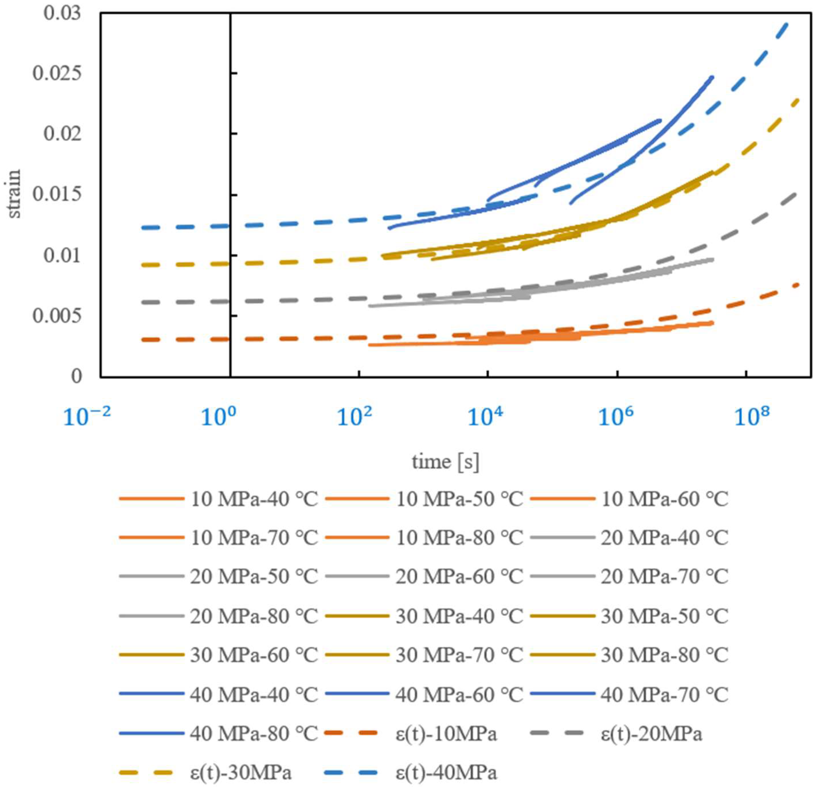
The most commonly used resin in CFRPs is epoxy resin; therefore, this study employed epoxy resin [25]. In this section, based on the creep test results of epoxy resin, the activation energy (), reference temperature (), and stress relaxation curve () were calculated. From the results, a master curve was obtained. DGBEA 50 g and 4,4′ DDS 16.3 g were mixed to create test specimens with dimensions of 60 mm in length, 10 mm in width, and 3 mm in thickness. Creep tests were conducted under stresses of 10 MPa, 20 MPa, 30 MPa, and 40 MPa, at temperatures of 40 °C, 50 °C, 60 °C, 70 °C, and 80 °C for each stress level, with each test lasting 1 h. The obtained creep test data were shifted using the Arrhenius-type temperature–time equivalence principle (Equation (16)). The parameters were set as .
Using creep compliance, a time-strain function was created and fitted to the creep test results. The creep compliance and strain function are shown in Equations (17) and (18), respectively. The constants were determined as . The results above are shown in Figure 1. The creep test results shifted using the temperature–time equivalence principle are indicated by solid lines, and the strain function obtained through fitting is indicated by dashed lines.

Figure 1.
fitted to the results of creep test.
The stress relaxation curve , which is necessary for determining the stiffness and viscosity coefficients of the matrix resin, was obtained by taking the inverse of , resulting in a master curve. Although this conversion requires a Laplace transform, numerical substitution and calculation showed that the values obtained by taking the inverse of were almost identical. Therefore, in this study, which deals with numerical calculations, they are considered equivalent. is shown in Equation (19)
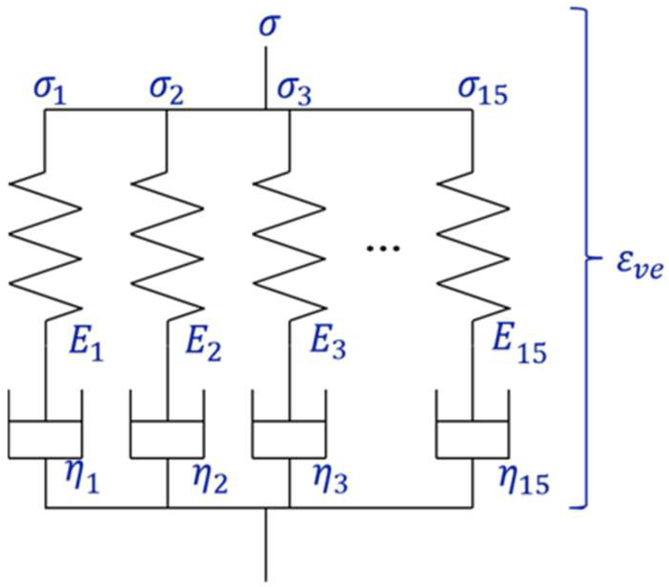
Next, for the 15 Maxwell models, which are described in detail in next section, the stiffness of each element was set to 220 MPa, and the viscosity coefficients were fitted (Figure 2). There are various fitting methods, but we aimed to reasonably represent the entire region by using Maxwell elements. So, to make it easier, we kept stiffness at a constant and adjusted the viscosity coefficients to match the master curve. A strain of 0.1 was assumed, and the equation used is shown in Equation (20). The determined stiffness and viscosity coefficients of each Maxwell element are presented in Table 1.
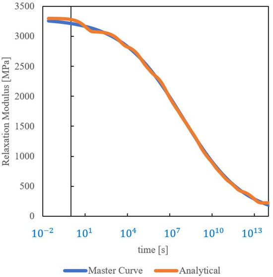
Figure 2.
Analytical curve fitted to master curve.

Table 1.
Material properties of springs and dashpots for viscoelastic model.
The determination of the nonlinear coefficient, as shown in Equation (22), was conducted. Using the same specimens as in the creep tests, a tensile test was performed at room temperature with a strain rate of 0.5% per second, and the numerical analysis results were fitted. The experimental and fitted analytical curves are shown in Figure 3. It was determined that , and .
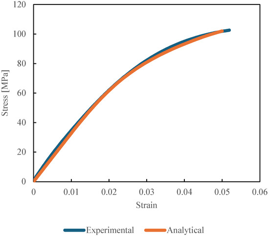
Figure 3.
Experimental and analytical stress–strain curve for determining nonlinear coefficient.
4. Numerical Procedures
4.1. Analysis Algorithm for the Matrix Resin
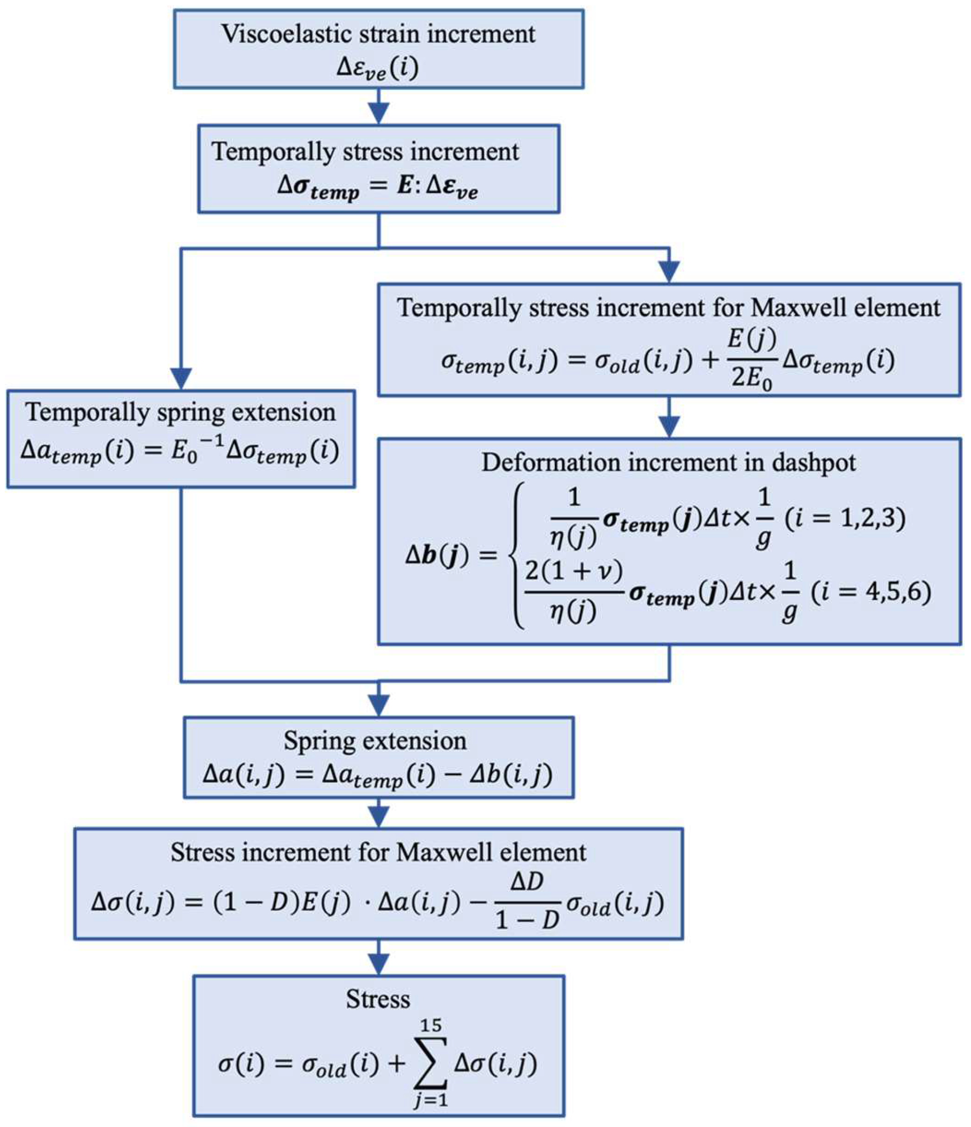
To represent strength degradation at the meso-scale, using numerical analysis results at the micro-scale based on entropy, we aim to apply the entropy damage criteria to the matrix resin of CFRPs and conduct numerical analyses at the micro-scale. By correlating the residual strength of CFRPs after fatigue loading with entropy generation and determining as a function of entropy, we intend to represent meso-scale strength degradation considering the results of micro-scale numerical simulations. In this study, a generalized Maxwell model, shown in Figure 4, was employed as the viscoelastic model, comprising 15 Maxwell elements. The material constants used were determined, as previously described. Analyses were conducted using Abaqus/Standard 2020, and the analysis algorithm for the epoxy resin matrix was implemented using the Abaqus/Standard user subroutine UMAT. The UMAT computational flow was shown in Figure 5. First, the strain increment is taken as the viscoelastic strain increment, and a temporary stress increment is calculated. From this temporary stress increment, the temporary spring extension and the temporary stress increment of the Maxwell elements are determined, and the deformation of the dashpot is calculated. Using the temporary spring extension and temporary dashpot deformation, the extension of the spring is computed, and the stress increment for each Maxwell element is determined. By summing the stress increments of each Maxwell element, the total stress increment is obtained. The , which is the stiffness matrix for calculating the temporary stress increment, is shown in Equation (21), and the , which is the nonlinear coefficient for calculating the deformation increment of the dashpot, is shown in Equation (22). Additionally, as shown in Equation (23), the entropy increment is calculated by dividing the dissipated energy, derived from the stress and dashpot displacement, by the absolute temperature. Furthermore, as shown in Equation (24), the cumulative entropy generation is obtained by adding the entropy increment determined in Equation (23) to the entropy from the previous increment, and the damage coefficient is determined in Equation (25) and carried over to the next increment. The stress of each Maxwell element and the total stress are carried over to the next increment and used in the calculation of the nonlinear coefficients and the dashpot elongation. When the damage coefficient (D) reaches 0.25, the element is considered to have failed, and element deletion is performed. This ensures that the failed elements no longer carry any stress. For the damage coefficient (Equation (25)), following the simple tensile test by Kudo et al. [25], the fracture entropy was set to 20 .

Figure 4.
Generalized Maxwell model for analyzing viscoelastic behavior.
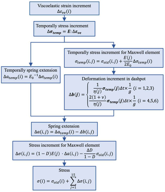
Figure 5.
Overall flowchart for updating stress.
4.2. Analysis Model and Conditions
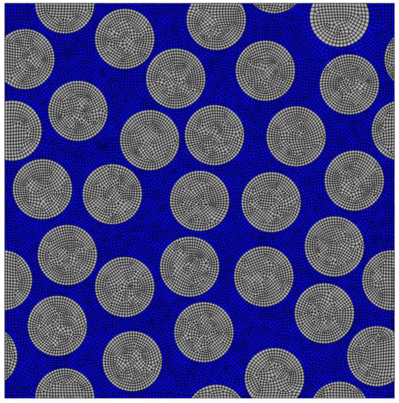
For the CFRP model, a three-dimensional unit cell analysis model of CFRPs, as shown in Figure 6, was utilized. The dimensions of the 3D unit cell were 39 μm × 39 μm × 0.3 μm. The carbon fibers had an elastic modulus of 14 GPa, a Poisson’s ratio of 0.3, and a diameter of 6 μm, with 30 fibers included at a volume fraction of 56%. This study did not consider the fiber/matrix interface. The element type used was an 8-node brick element. The epoxy resin matrix was assumed to be a nonlinear viscoelastic material, following a constitutive equation that considers entropy damage. The analysis model applied periodic boundary conditions to all edges using the key degree of freedom method [36,37,38,39,40].
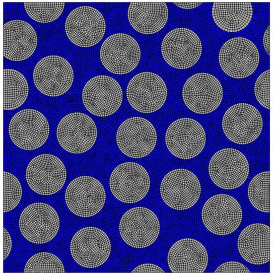
Figure 6.
Finite element model of CFRPs.
For the cyclic tensile analysis, as shown in Figure 7, Dummy-Y was subjected to repeated tensile loading in the Y-axis direction. Displacement control was used to apply strains of 0.1%, 0.2%, 0.3%, 0.4%, 0.5%, 0.7%, and 0.8% for 5, 10, 20, 40, and 80 cycles. The average entropy increase of all elements at the end of each cycle was calculated, and after completing the cycles, tensile fracture was induced at a strain rate of 0.1%/s to determine the residual strength as the maximum stress at fracture.
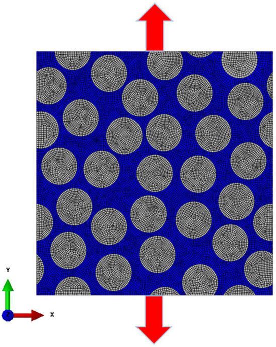
Figure 7.
Finite element model for analyzing cyclic tensile and global strain.
For the cyclic out-of-plane shear analysis, as shown in Figure 8, the central node was introduced onto the fixed displacement to avoid rigid body displacement, and a Dummy-X was subjected to repeated shear loading in the Z-axis direction. Displacement control was used to apply strains of 0.1%, 0.2%, 0.3%, 0.4%, 0.5%, 0.6%, 0.7%, and 0.8% for 5, 10, 20, 40, and 80 cycles. The average entropy increase of all elements at the end of each cycle was calculated, and after completing the cycles, tensile fracture was induced at a strain rate of 0.1%/s to determine the residual strength as the maximum stress at fracture.
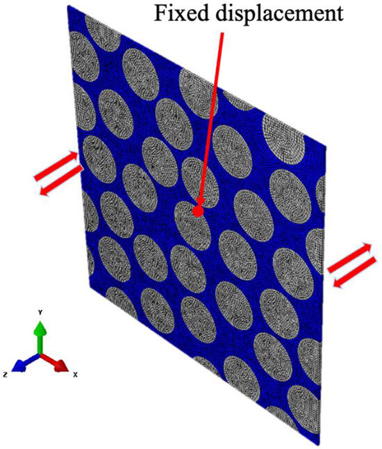
Figure 8.
Finite element model for analyzing cyclic-out-of-plane shear and global strain.
5. Results
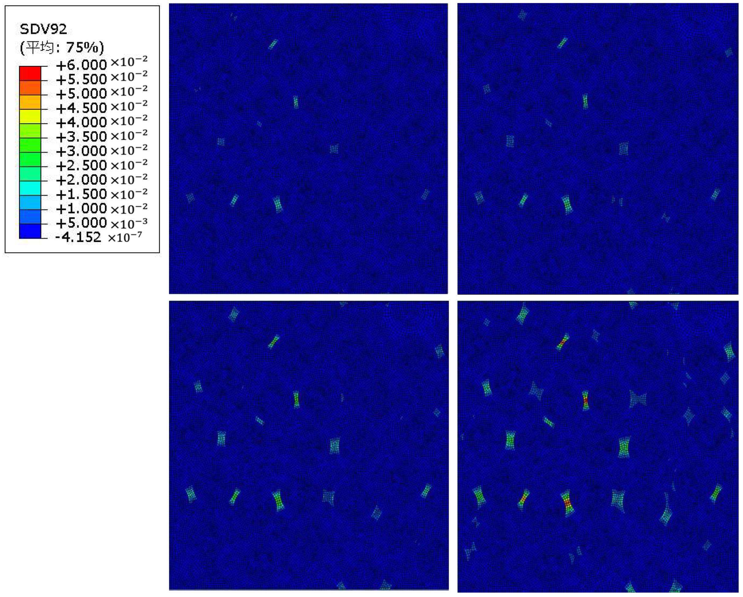
As an example of the analysis results, Figure 9 shows the damage state after applying repeated tensile loading at a strain of 0.8% for 10 cycles, 20 cycles, 40 cycles, and 80 cycles. The maximum damage coefficient, which is an index that represents damage, is set to D = 0.25, indicating that the damage coefficient increases from blue to red. Similarly, Figure 10 shows the damage state after applying repeated out-of-plane shear loading at a strain of 0.8% for 10 cycles, 20 cycles, 40 cycles, and 80 cycles. Again, the maximum damage coefficient is set to D = 0.06, indicating that the damage coefficient increases from blue to red. In both analyses, as the number of load cycles increases, the damage also increases.
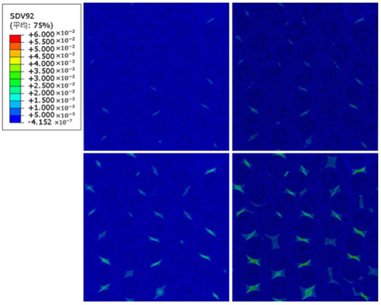
Figure 9.
Damage coefficient after cyclic tensile loading (strain 0.8%, 10 cycle (upper left), 20 cycle (upper right), 40 cycle (lower left), and 80 cycle (lower right)).
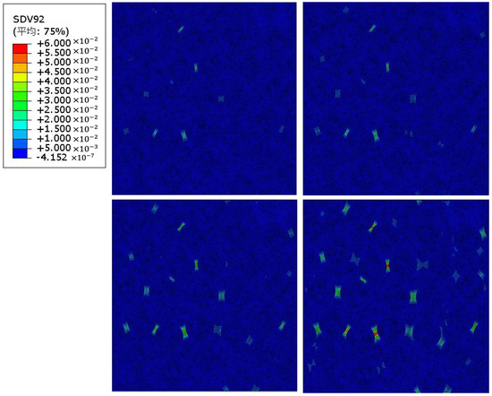
Figure 10.
Damage coefficient after cyclic out-of-plane shear loading (strain 0.8%, 10 cycle (upper left), 20 cycle (upper right), 40 cycle (lower left), and 80 cycle (lower right)).
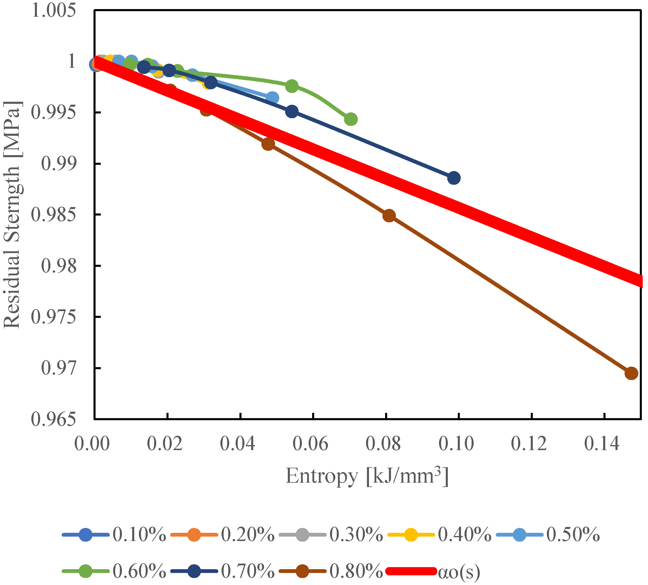
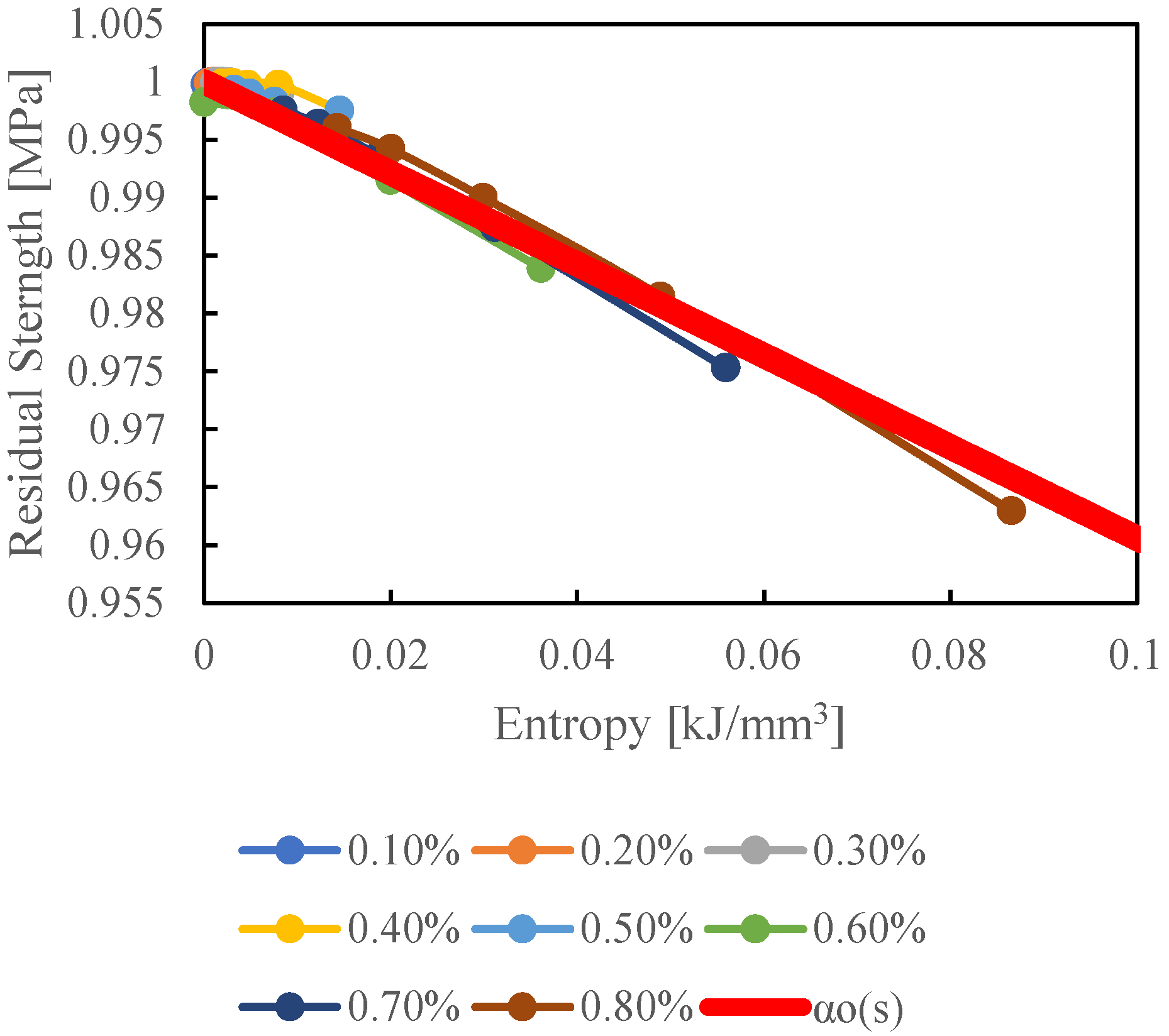
The relationship between residual strength and entropy derived from cyclic tensile and cyclic out-of-plane shear analyses was fitted with as a linear function, and is shown in Figure 11 for cyclic tensile analysis and Figure 12 for cyclic out-of-plane shear analysis. In both the cyclic tensile analysis and the cyclic out-of-plane shear analysis, it was found that an increase in entropy leads to a decrease in residual strength. The determined values for each analysis are presented in Equations (26) and (27). The residual strength was standardized.
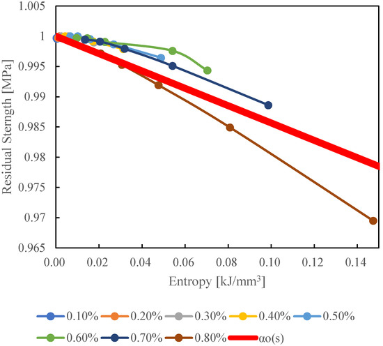
Figure 11.
fitted to the relationship between entropy and standardized residual strength under cyclic tensile loading.

Figure 12.
fitted to the relationship between entropy and standardized residual strength under cyclic out-of-plane shear loading.
6. Conclusions
In this study, we conducted micro-scale numerical simulations to evaluate the residual strength of CFRPs subjected to cyclic transverse and out-of-plane shear loading fatigue, using a finite element method. By incorporating an entropy-based damage criterion for the matrix resin, we established a linear relationship, which is in Hashin’s criteria, between entropy accumulation and strength degradation. The simulations demonstrated that increased entropy, resulting from cyclic loading, directly correlates with decreased residual strength in CFRPs. Material constants for the epoxy resin matrix were determined through creep and tensile tests, and a generalized Maxwell model was used to represent viscoelastic behavior. The Abaqus/Standard 2020 software facilitated these analyses with the epoxy resin matrix behavior implemented via a UMAT subroutine. The linear relationship between entropy and residual strength was validated for both cyclic tensile and shear loading conditions. This suggests that using entropy generation allows for a comprehensive assessment of damage under various loading histories. This approach enhances experimental insights with numerical predictions, offering a comprehensive understanding of CFRP strength degradation under fatigue loading. The findings underscore the potential of micro-scale numerical simulations to accurately predict meso-scale strength degradation, thus contributing significantly to the material design and durability assessment of CFRPs in practical applications. This research pioneers the integration of micro-scale resin-specific entropy with macro-scale strength degradation in CFRP, establishing a world-first computational framework that advances our understanding of the material’s fatigue behavior and its application in complex engineering environments.
Author Contributions
Conceptualization, J.K.; methodology, J.K.; software, T.S.; validation, J.K.; formal analysis, T.S.; investigation, T.S.; resources, T.S.; data curation, T.S.; writing—original draft preparation, T.S.; writing—review and editing, T.S. and N.K.; visualization, T.S.; supervision, J.K.; project administration, J.K.; funding acquisition, J.K. All authors have read and agreed to the published version of the manuscript.
Funding
The work was supported by the JST-Mirai Program [221036344].
Institutional Review Board Statement
Not applicable.
Informed Consent Statement
Not applicable.
Data Availability Statement
The data are contained within the article.
Conflicts of Interest
The authors declare no conflicts of interest.
References
- Banks-Sills, L.; Choron, T.; Simon, I. Effect of number of fatigue cycles on fatigue data: CFRP (prepreg and wet-layup). Fatigue Fract. Eng. Mater. Struct. 2024, 47, 833–848. [Google Scholar] [CrossRef]
- Nishi, Y.; Hosoi, A.; Kawada, H. Evaluation of matrix crack growth in interlaminar toughened quasi-isotropic carbon-fiber reinforced plastic laminates up to the very-high cycle regime by ultrasonic fatigue testing. Compos. Sci. Technol. 2024, 253, 110623. [Google Scholar] [CrossRef]
- Singh, K.K.; Sharma, N. Fatigue behavior of symmetric and asymmetric carbon and basalt fiber-reinforced polymer composites in transverse loading. J. Braz. Soc. Mech. Sci. Eng. 2024, 46, 245. [Google Scholar] [CrossRef]
- Lei, Z.; Pan, R.; Sun, W.; Dong, Y.; Wan, Y.; Yin, B. Fatigue damage mechanisms and evolution of residual tensile strength in CFRP Composites: Stacking sequence effect. Compos. Struct. 2024, 330, 117818. [Google Scholar] [CrossRef]
- Gerdes, L.; Mrzljak, S.; Keuntje, J.; Wippo, V.; Jaeschke, P.; Walther, F. Fatigue performance of laser cut carbon fiber-reinforced epoxy and polyamide 6 considering specimen width. Mater./Mater. Test. 2023, 65, 1645–1656. [Google Scholar] [CrossRef]
- Frik, M.; Benkedjouh, T.; Essaidi, A.B.; Boumediene, F. Advancing Damage Assessment of CFRP-Composite through BILSTM and Hilbert Upper Envelope Analysis. Russ. J. Nondestruct. Test. 2023, 59, 1241–1258. [Google Scholar] [CrossRef]
- Jia, Z.; Garnier, C.; Pastor, M.-L.; Rousseau, J.; Gong, X. Experimental investigation of impacted multidirectional laminates under compressive static and cyclic loading. Compos. Struct. 2023, 322, 117335. [Google Scholar] [CrossRef]
- Jia, Z.; Pastor, M.-L.; Garnier, C.; Gong, X. Fatigue life determination based on infrared thermographic data for Multi-Directional (MD) CFRP composite laminates. Compos. Struct. 2023, 319, 117202. [Google Scholar] [CrossRef]
- Morgado, G.F.D.M.; Montagna, L.S.; Gouvêa, R.F.; Guimarães, A.; Passador, F.R.; Rezende, M.C. Fatigue and durability assessment of PA6-based carbon fiber composites for lightweight applications. J. Compos. Mater. 2023, 57, 4227–4238. [Google Scholar] [CrossRef]
- Nishi, Y.; Itoh, S.; Hosoi, A.; Kawada, H. Stress and energy release rate analysis of cross-ply carbon fiber-reinforced plastic laminate with transverse cracks subjected to ultrasonic vibration using a variational approach. Adv. Compos. Mater. 2024, 33, 1224–1238. [Google Scholar] [CrossRef]
- Wu, Y.; Gong, Y.; Tian, D.; Zou, L.; Zhao, L.; Zhang, J.; Hu, N. Influence of curing pressure on the mode I static and fatigue delamination growth behavior of CFRP laminates. Compos. Struct. 2023, 322, 117345. [Google Scholar] [CrossRef]
- Vishe, N.J.; Mulani, S.B.; Roy, S. Repeatable self-healing of composite’s fatigue delamination. Compos. Struct. 2023, 311, 116846. [Google Scholar] [CrossRef]
- Li, X.; Benedictus, R.; Zarouchas, D. Analysis of Stochastic Matrix Crack Evolution in CFRP Cross-Ply Laminates under Fatigue Loading. Eng. Fail. Anal. 2023, 150, 107277. [Google Scholar] [CrossRef]
- Aoki, R.; Higuchi, R.; Yokozeki, T. Progressive damage and residual strength of open-hole thin-ply CFRP laminates under tensile fatigue loading. Compos. Struct. 2023, 314, 116973. [Google Scholar] [CrossRef]
- Mrzljak, S.; Zanghellini, B.; Gerdes, L.; Helwing, R.; Schuller, R.; Sinn, G.; Lichtenegger, H.; Walther, F.; Rennhofer, H. Effect of carbon nanofibre orientation on fatigue properties of carbon fibre-reinforced polymers. J. Compos. Mater. 2023, 57, 1149–1164. [Google Scholar] [CrossRef]
- Guo, Y.-E.; Shang, D.-G.; Zuo, L.-X.; Qu, L.-F.; Cai, D.; Jin, T.; Li, D.-H. Fatigue life prediction considering strength contribution of fibre layers with different orientations for CFRP laminates at high temperature. Compos. Struct. 2023, 306, 116604. [Google Scholar] [CrossRef]
- Kitagawa, Y.; Arai, M.; Yoshimura, A.; Goto, K. Prediction of transverse crack multiplication of CFRP cross-ply laminates under tension-tension fatigue load. Adv. Compos. Mater. 2023, 32, 419–436. [Google Scholar] [CrossRef]
- Aoki, R.; Higuchi, R.; Yokozeki, T. Fatigue simulation for progressive damage in CFRP laminates using intra-laminar and inter-laminar fatigue damage models. Int. J. Fatigue 2021, 143, 106015. [Google Scholar] [CrossRef]
- Mehdizadeh, M.; Khonsari, M.M. On the application of fracture fatigue entropy to variable frequency and loading amplitude. Theor. Appl. Fract. Mech. 2018, 98, 30–37. [Google Scholar] [CrossRef]
- Naderi, M.; Amiri, M.; Khonsari, M.M. On the thermodynamic entropy of fatigue fracture. Proc. R. Soc. A Math. Phys. Eng. Sci. 2009, 466, 423–438. [Google Scholar] [CrossRef]
- Naderi, M.; Khonsari, M.M. An experimental approach to low-cycle fatigue damage based on thermodynamic entropy. Int. J. Solids Struct. 2010, 47, 875–880. [Google Scholar] [CrossRef]
- Naderi, M.; Khonsari, M.M. A thermodynamic approach to fatigue damage accumulation under variable loading. Mater. Sci. Eng. A 2010, 527, 6133–6139. [Google Scholar] [CrossRef]
- Liakat, M.; Khonsari, M.M. On the anelasticity and fatigue fracture entropy in high-cycle metal fatigue. Mater. Des. 2015, 82, 18–27. [Google Scholar] [CrossRef]
- Sakai, T.; Oya, Y.; Koyanagi, J. Evaluation of volumetric strain on Polyamide 6 by thermodynamic entropy generation. Exp. Mech. 2024, 64, 105–111. [Google Scholar] [CrossRef]
- Kudo, N.; Fujita, R.; Oya, Y.; Sakai, T.; Nagano, H.; Koyanagi, J. Identification of invisible fatigue damage of thermosetting epoxy resin by non-destructive thermal measurement using entropy generation. Adv. Compos. Mater. 2024, 33, 233–249. [Google Scholar] [CrossRef]
- Deng, H.; Mochizuki, A.; Fikry, M.; Abe, S.; Ogihara, S.; Koyanagi, J. Numerical and experimental studies for fatigue damage accumulation of CFRP cross-ply laminates based on entropy failure criterion. Materials 2023, 16, 388. [Google Scholar] [CrossRef]
- Sakai, T.; Takase, N.; Oya, Y.; Koyanagi, J. A possibility for quantitative detection of mechanically induced invisible damage by thermal property measurement via entropy generation for a polymer material. Materials 2022, 15, 737. [Google Scholar] [CrossRef]
- Sato, M.; Hasegawa, K.; Koyanagi, J.; Higuchi, R.; Ishida, Y. Residual Strength Prediction for Unidirectional CFRP Using a Nonlinear Viscoelastic Constitutive Equation Considering Entropy Damage. Compos. Part A 2021, 141, 106178. [Google Scholar] [CrossRef]
- Yamada, N.; Morita, M.; Takamura, M.; Murashima, T.; Oya, Y.; Koyanagi, J. Molecular Dynamics Simulation of Cumulative Microscopic Damage in a Thermosetting Polymer under Cyclic Loading. Polymers 2024, 16, 1813. [Google Scholar] [CrossRef]
- Iwamoto, S.; Oya, Y.; Koyanagi, J. Evaluation of microscopic damage of PEEK polymers under cyclic loadings using molecular dynamics simulations. Polymers 2022, 14, 4955. [Google Scholar] [CrossRef]
- Bryant, M.D.; Khonsari, M.M.; Ling, F.F. On the thermodynamics of degradation. Proc. R. Soc. A Math. Phys. Eng. Sci. 2008, 464, 2001–2014. [Google Scholar] [CrossRef]
- Li, Y.; Deng, H.; Takamura, M.; Koyanagi, J. Durability analysis of CFRP adhesive joints: A study based on entropy damage modeling using FEM. Materials 2023, 16, 6821. [Google Scholar] [CrossRef] [PubMed]
- Deng, H.; Toda, K.; Sato, M.; Koyanagi, J. Micro-scale numerical simulation of fatigue failure for CFRP subjected to multiple-amplitude cyclic loadings based on entropy damage criterion. Materials 2023, 16, 6120. [Google Scholar] [CrossRef] [PubMed]
- Kudo, N.; Sekino, T.; Fikry, M.J.M.; Koyanagi, J. Numerical Simulation of the Frequency Dependence of Fatigue Failure for a Viscoelastic Medium Considering Internal Heat Generation. Materials 2024, 17, 6202. [Google Scholar] [CrossRef] [PubMed]
- Koyanagi, J.; Mochizuki, A.; Higuchi, R.; Tan, V.B.C.; Tay, T.E. Finite element model for simulating entropy-based strength-degradation of carbon-fiber-reinforced plastics subjected to cyclic loadings. Int. J. Fatigue 2022, 165, 107204. [Google Scholar] [CrossRef]
- Li, S.; Warrior, N.; Zou, Z.; Almaskari, F. A unit cell for FE analysis of materials with the microstructure of a staggered pattern. Compos. Part A Appl. Sci. Manuf. 2011, 42, 801–811. [Google Scholar] [CrossRef]
- Melro, A.R.; Camanho, P.P.; Andrade Pires, F.M.; Pinho, S.T. Micromechanical analysis of polymer composites reinforced by unidirectional fibres: Part II-Micromechanical analyses. Int. J. Solids Struct. 2013, 50, 1906–1915. [Google Scholar] [CrossRef]
- Li, S.; Jeanmeure, L.F.C.; Pan, Q. A composite material characterisation tool: UnitCells. J. Eng. Math. 2015, 95, 279–293. [Google Scholar] [CrossRef]
- Higuchi, R.; Yokozeki, T.; Nagashima, T.; Aoki, T. Evaluation of mechanical properties of noncircular carbon fiber reinforced plastics by using XFEM-based computational micromechanics. Compos. Part A Appl. Sci. Manuf. 2019, 126, 105556. [Google Scholar] [CrossRef]
- Sato, M.; Shirai, S.; Koyanagi, J.; Ishida, Y.; Kogo, Y. Numerical simulation for strain rate and temperature dependence of transverse tensile failure of unidirectional CFRP. J. Compos. Mater. 2019, 53, 4305–4312. [Google Scholar] [CrossRef]


Disclaimer/Publisher’s Note: The statements, opinions and data contained in all publications are solely those of the individual author(s) and contributor(s) and not of MDPI and/or the editor(s). MDPI and/or the editor(s) disclaim responsibility for any injury to people or property resulting from any ideas, methods, instructions or products referred to in the content. |
© 2025 by the authors. Licensee MDPI, Basel, Switzerland. This article is an open access article distributed under the terms and conditions of the Creative Commons Attribution (CC BY) license (https://creativecommons.org/licenses/by/4.0/).