Article

Enhancing Phase Change Characteristics of Hybrid Nanocomposites for Latent Heat Thermal Energy Storage

by
Jidhesh Perumalsamy
1,
Swami B. M. Punniakodi
2,
Chandrasekaran Selvam
3,* and
Ramalingam Senthil
3,*
1
Renault Nissan Technology and Business Centre India, Chennai 603002, India
2
Department of Mechanical Engineering, Faculty of Engineering and Technology, SRM Institute of Science and Technology, Ramapuram Campus, Chennai 600089, India
3
Department of Mechanical Engineering, SRM Institute of Science and Technology, Kattankulathur, Chennai 603203, India
*
Authors to whom correspondence should be addressed.
J. Compos. Sci. 2025, 9(3), 120; https://doi.org/10.3390/jcs9030120
Submission received: 23 January 2025 / Revised: 13 February 2025 / Accepted: 2 March 2025 / Published: 4 March 2025
(This article belongs to the Special Issue Composite Materials for Energy Management, Storage or Transportation)

Abstract

:
Thermal energy storage systems store intermittent solar energy to supply heat during non-solar hours. However, they often exhibit poor thermal conductivity, hindering efficient energy storage and release. The purpose of this study is to enhance the phase change characteristics of a paraffin wax-based latent heat energy storage system using a hybrid nanocomposite while increasing its thermal conductivity. Present heat storage systems integrate nanomaterials into a phase change material (paraffin wax) for faster energy storage and release in the form of heat. Steatite and copper oxide are chosen as nanomaterial additives in this experimental investigation. The charging and discharging characteristics of latent heat energy storage systems are studied using four different cases involving pure paraffin wax (case 1), paraffin wax with 10 wt% steatite (case 2), paraffin wax with 10 wt% copper oxide (case 3), and 5 wt% steatite with 5 wt% copper oxide (case 4). The charging and discharging rates were studied. The solidification rate of the nanocomposite improved with the addition of nanomaterials. The paraffin wax with 10 wt% copper oxide (case 3) outperformed the other cases, showing the best heat transfer ability and achieving an overall fusion time of 90 min. Case 3 was found to be the most thermally effective among the other cases. A significant finding of this study is the enhanced thermal performance of paraffin wax-based LHS systems using CuO and steatite nanocomposites, which hold great potential for practical applications. These include solar thermal systems, where efficient energy storage is critical, and industrial heat recovery systems, where optimizing heat transfer and storage can significantly improve energy utilization and sustainability.

1. Introduction

Economic instability around the world needs a conservative approach to sustain energy needs. Daily energy needs are contributed by fossil fuel usage, which pollutes the atmosphere [1]. Renewable energy sources like solar, wind, and geothermal sources are used to address these environmental challenges [2]. Solar energy is abundantly available but highly intermittent. Most domestic heating applications are required during off-sunshine hours. A supply-and-demand gap exists in the solar energy context. Hence, thermal energy storage (TES) systems are used to overcome the intermittency of solar energy by storing heat at peak times [3]. Latent heat storage (LHS) materials are more effective in energy storage density than sensible heat-type storage materials [4]. However, LHS materials suffer from poor thermal conductivity, and studies have been performed to alleviate this effect [5,6]. Many studies have been conducted to expedite the energy storage/release of phase change material (PCM) using nanoparticles, fins, metal mesh, and heat transfer tubes at an optimal location and in an optimal container orientation [7,8]. Mukhesh et al. [9] investigated thermal convection in a heat transfer tube (HTT) within a rectangular container, observing asymmetrical melting dominated by diffusion near the bottom and convection plumes above the HTT. The study highlighted the influence of unmelted PCM topography and the role of Reynolds and Stefan numbers in convection plume development. The solidification rate increased by 44%, emphasizing the need for optimal nanoparticle use to balance thermal conductivity and viscosity [10].
Thangapandian et al. [11] developed an artificial neural network to predict lauric acid’s thermal conductivity and viscosity with copper oxide (CuO) and Al2O3 nanoparticles (1.25–10 wt%). Nanoparticles increased thermal conductivity and viscosity, with minimal errors between experimental and numerical values. Mishra et al. [12] optimized PCM melting using different container designs, with their inverted semicircular container yielding the best results. Talele and Zhao [13] demonstrated that nano-enhanced PCM (NePCM) improves battery thermal management. Patel et al. [14] simulated direct-contact heat exchangers, showing that increased HTF flow rate and temperature improved heat transfer. Athawale et al. [15] studied a packed bed TES system with encapsulated PCM capsules, finding that structured packing reduced melting time by 23.56% for 2.5 mm capsules. HTF temperature and flow rate significantly impacted melting rates. Teja et al. [16] optimized PCM melting in a packed bed TES system by inclining capsules at 2.5° and adding MWCNT nanoparticles. A 13.6% melting rate improvement was observed at 3% MWCNT, with diminishing returns at higher concentrations. These studies highlight the potential of nanoparticles and optimized designs to enhance PCM thermal performance, with applications in solar energy, cold storage, and battery thermal management. Optimal nanoparticle concentration and system design are critical for maximizing efficiency.
Das et al. [17] studied PCM melting in capsules with metal foams, finding that increasing their porosity to 70% boosted energy storage by 5.41%, while larger capsule diameters (7–11 mm) increased storage by 211.9%. Nahak et al. [18] modeled a packed bed energy storage system with PCM-filled capsules, considering HTF flow, heat transfer, and natural convection during melting. Bharathiraja et al. [19] enhanced wax PCM thermal conductivity by 32–46% using MWCNT and nano-SiO2 at 0.5–1 wt%, with nanoparticle concentration affecting melting and solidification temperatures. Salt hydrate PCM thermal conductivity was increased using MWCNT and functionalized MWCNT, achieving 0.78–0.92 W/m·K and a 14.66–31.17% increase in LHS [20]. Duan et al. [21] optimized PCM melting in a shell-and-tube system with fins, finding that case F (HTT near the bottom with top fins) melted 21.12% faster. Punniakodi and Senthil [22] showed that a helical coil HTT near the container bottom enhanced melting, while fully spread coils improved solidification. Chatterjee et al. [23] analyzed lauric acid and n-Octadecane PCMs in trapezoidal enclosures, noting that cavity shape and HTT location influenced melting. The solar concentrated absorbers utilized PCM charging and discharging to produce uniform temperature distribution [24]. Sutradhar et al. [25] found that copper metal foam increased PCM melting and solidification times by 31.25% and 107.5%, respectively. Jeyaseelan et al. [26] reduced solar salt charging time to 70–180 min using vertical inserts in shell-and-tube systems. Alqaed et al. [27] simulated NePCM with graphene and CaCl2·6H2O in a circular enclosure, showing longer blade lengths and reduced melting times. Table 1 summarizes the significant aspects of selective PCMs and nano-additives.
Sivashankar et al. [37] enhanced photovoltaic efficiency with triangular pin fin heat sinks and graphene-enhanced PCM. Venkatraman et al. [38] improved LHS system discharge using steatite nanoparticles, maintaining hot water temperatures longer. Carnauba wax with nanoclay montmorillonite improved thermal conductivity and LHS [39]. A 54 W Bismuth Telluride thermoelectric cooler performed better with PCM-filled heat sinks under varying conditions [40]. These studies highlight the effectiveness of nanoparticles, metal foams, and optimized designs in enhancing PCM thermal performance for applications like energy storage, solar systems, and thermal management. Optimal nanoparticle concentrations and system configurations are critical for maximizing efficiency. The addition of nanoclay improved stability, prevented leakage, accelerated heat cycles, and achieved a latent heat increase of 69.5–107.9 kJ/kg. Adding 1% of graphene nanoplatelets could increase the thermal conductivity of wax-based PCMs two-fold without sacrificing latent heat [41]. Pereira et al. [42] examined NePCM for energy harvesting and conversion, discussing thermophysical properties, improvement techniques, and their impact on solar thermal efficiency, setting guidelines for future research. Khlissa et al. [43] explored PCMs for TES, highlighting advancements in nano-encapsulated PCMs, improved thermal performance, challenges, and future directions for enhancing PCM efficiency and applications. NePCMs incorporating Cu-decorated graphene oxide significantly improved TES performance, with a 12.07% increase in latent heat and a 12.5% increase in thermal conductivity at optimal concentrations [44].
Graphene–silver nanopowder in paraffin RT50 significantly improved thermal conductivity by 53.85% with minimal impact on latent heat, ensuring enhanced TES performance [45]. Using NePCM with circular pin fins significantly reduced the base temperature of electronic devices, with a 25.83% reduction at 6 wt% NePCM concentration [46]. A packed bed TES system is used with varying sizes of capsules and HTF flow rates and temperatures to enhance PCM fusion for use in applications for faster storage/release [47,48]. Yadav et al. [49] demonstrated a 104.2% improvement in the thermal conductivity of PEG–PCM at 0.7 wt% MWCNT, which has stable thermal and chemical properties and is suitable for waste heat recovery applications. Paul et al. [50] evaluated the thermophysical properties of a novel PEG400/MXene nanocomposite. They achieved a 17.98% increase in the thermal conductivity of a PEG nanocomposite and stated its potential for enhanced cold chain logistics. Apmann et al. [51] reviewed the optimization of nanoparticle effects in terms of nanocharacteristics, such as size, shape, and material. Shchegolkov et al. [52] investigated graphene-modified sodium acetate (≈5000 W/(m K)) to enhance stability and control heat dissipation with charge/discharge modes. They applied heat accumulators in thermotherapy and methane tanks to stabilize the temperature.
Our literature survey shows studies on enhancing PCM melting using GO, CuO, and MWCNT as nanoparticles to enhance PCM fusion for TES. Metal foams are used in capsules to enhance fusion. Nanoparticles of varying proportions are used to expedite PCM fusion. Different PCMs are used together to produce a cascading effect in a heat exchanger to enhance fusion. Previous studies indicate that nanoparticles enhance fusion in paraffin wax-based TES. However, few studies use a combination of steatite and CuO nanoparticles in a horizontal TES system with a helical HTT. This study aims to enhance the thermal performance of a paraffin wax-based LHS system by adding steatite and CuO nanocomposites to optimize energy storage and release efficiency. This study investigates nanocomposite PCM to enhance PCM fusion and increase its use in many TES applications. Four different configurations, namely, case 1—PCM, case 2—PCM with steatite (10 wt%), case 3—PCM with CuO (10 wt%), and case—4 PCM with steatite (5 wt%) and CuO (5 wt%), are used in a TES container to enhance fusion. Due to effective heat transfer, CuO nanoparticles enhance PCM fusion more than other cases. The effective heat transferability is due to heat transfer network paths. This study consists of different sections: the Introduction Section, which briefly discusses the various studies carried out in the field of TES to enhance fusion; the Materials and Methods Section, which discusses the materials and experimental test facility used; and the Results and Discussion Section, which discusses the process and performance of TES systems. Finally, this study concludes with important remarks on thermal storage rate and future research perspectives.

2. Materials and Methods

2.1. Preparation of Nano-Enhanced PCM

This study uses commercially available paraffin wax as the PCM (http://www.rubitherm.eu/) (Accessed on 20 October 2024) due to its higher latent heat (195 kJ/kg). CuO and steatite nanoparticles are made into a NePCM. CuO and steatite purchased from Alfa Aesar and CoorsTek are used as nanoparticles for this study. CuO is known for its thermal conductivity, which enhances heat transfer. Steatite (Magnesium silicate) is a porous material that enhances diffusion and heat transfer. These materials are mixed with paraffin wax to improve NePCM’s thermal conductivity. The increased thermal conductivity and heat storage/release rate of NePCM expedites fusion for solar thermal applications. Further, the CuO and steatite nanoparticles are smaller than 50 nm and 100 nm. These sizes are finer to avoid agglomeration and sedimentation, resulting in enhanced heat transfer. Finer particles improve the mixing of CuO and steatite. They enhance dispersion in paraffin wax, thereby increasing thermal conductivity. The smaller size provides a high surface area-to-volume ratio, enabling effective heat transfer. Though the density of CuO is high, the finer size helps avoid agglomeration and settling. The CuO nanoparticle used for this study is smaller, making the heat-accumulating composite lighter. The thermophysical properties of the chosen materials are presented in Table 2.
The single and hybrid NePCMs were prepared with the selected nanomaterials. A 10% weight fraction was considered for preparing mono-NePCM, while 5 wt% CuO and 5 wt% steatites were considered for hybrid NePCM. Initially, the required quantity of solid PCM was melted with the hot plate magnetic stirrer to turn it into liquid. Then, the 10 wt% CuO nanoparticles were dispersed in a liquid PCM and stirred well with the hot plate magnetic stirrer to form a stable (Cuo-PCM) mono-NePCM. The same procedure was repeated to prepare (steatite-PCM) mono-NePCM and hybrid NePCM.

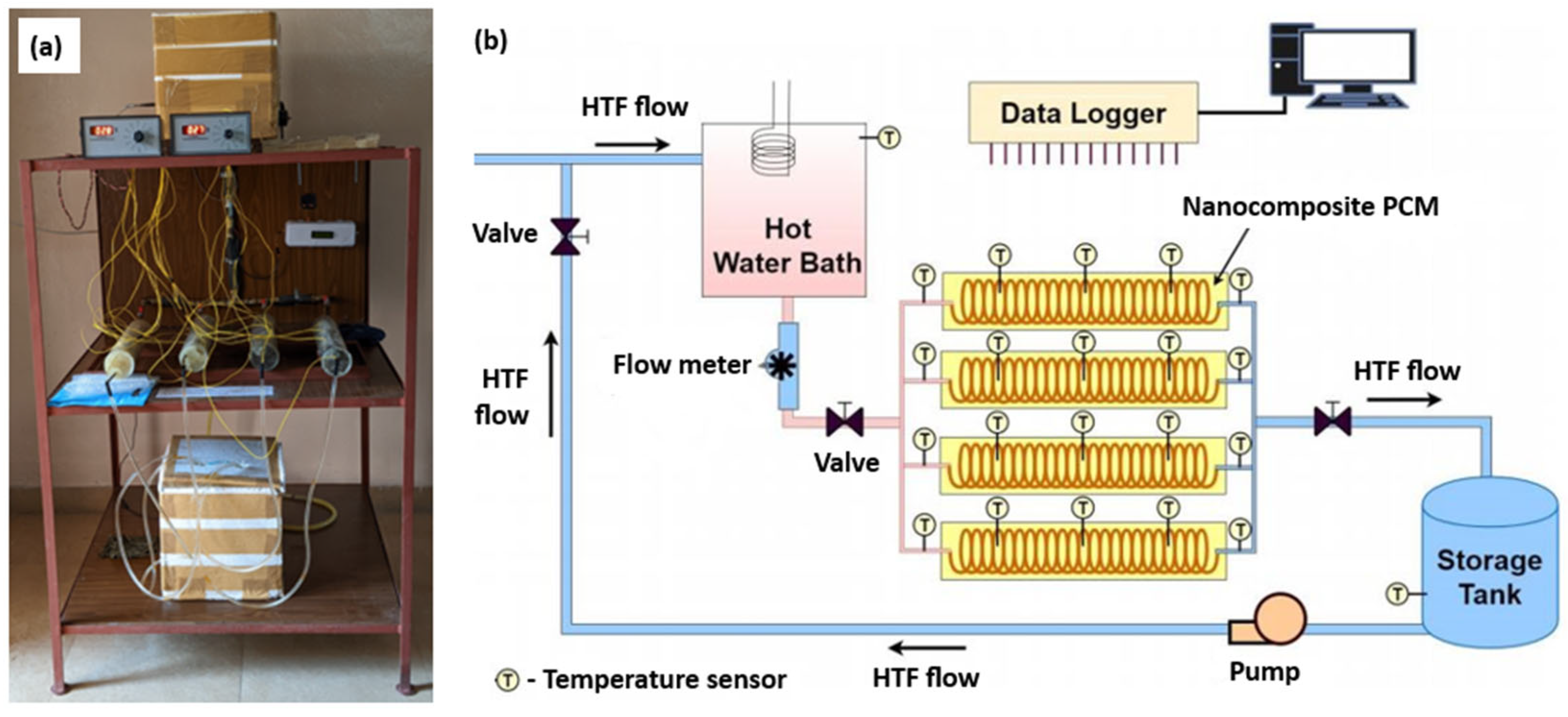
2.2. Experimental Test Facility

The experimental test facility consists of a supply tank, reservoir, horizontal TES container, helical HTT, and piping system with valves. The hot HTF flows from the supply tank to the TES container through the piping system. It flows into four TES systems via a helical HTT. The four TES systems consist of different cases. Melting and solidification are performed using HTF at 70 °C and 25 °C. A thermostat is attached to the supply tank to maintain a constant HTF temperature. The HTF flow is maintained constantly using valves. The PCM and HTF temperature is measured using a K-type thermocouple. Figure 1 illustrates the experimental setup.
The thermocouples are inserted into a PCM container to measure temperature during fusion. Initially, the valves to the sink are kept closed. The cold HTF from the storage tank is heated with the water heater. It then passes through the PCM and is filled with different weight concentrations of various nano-additives, losing its heat to the PCM. It then flows to the storage tank. In this way, PCM gains heat energy, which will be used for heating and other general-related applications. The HTF is drained into the sink after losing heat energy to the PCM. The HTF is again pumped into the heat source. The hot HTF is uniformly distributed among the four PCM-filled chambers in the acrylic tube and collected using suitable-sized valves. The temperature indicator is fitted along the length of the chambers to identify the temperature distribution in the PCM. The helical HTT is placed inside the horizontal TES container. The HTT is made of copper to facilitate high heat transfer. Copper has high thermal conductivity and good corrosion resistance. The helical HTT is spread throughout the horizontal TES container for faster heat storage/release. HTF flows through the helical HTT to melt and solidify the PCM during heat storage/release.

2.3. Experimental Procedure

This experiment utilizes thermocouples to accurately monitor the PCM and HTF temperature throughout the process. Before their use, all the thermocouples undergo rigorous calibration procedures to ensure precise measurements during the experiment. A total of 12 thermocouples are strategically positioned at various locations within the system to record temperature data at one-minute intervals. This setup allows for continuous, high-resolution temperature monitoring over time, facilitating a detailed analysis of the thermal dynamics. The experiment begins with the charging phase, where heated HTF is circulated through a tube containing PCM. During this stage, the HTF transfers heat to the PCM, causing it to absorb thermal energy and undergo a phase transition from solid to liquid. The charging phase continues until the PCM temperature reaches and exceeds its melting point. Once the PCM is completely melted, the system transitions to the discharging phase, where colder HTF is passed through the tube. This cool HTF absorbs the stored thermal energy from the PCM, resulting in the material’s solidification. Throughout both the charging and discharging processes, variations in HTF mass flow rate and inlet temperature are systematically applied to investigate their effects on the thermal storage and release efficiency of the PCM system.
The charging process is carried out with higher HTF inlet temperatures to accelerate the heating of the PCM. In comparison, the discharging phase employs lower inlet temperatures to promote efficient heat extraction from PCM. By adjusting these parameters, the experiment aims to explore the thermal performance and energy storage capabilities of the PCM under different operating conditions. All experimental data, including temperature measurements and flow rates, are recorded simultaneously and analyzed to understand the heat transfer mechanisms and the impact of various variables on the thermal behavior of the system. The results are then used to assess the efficiency and effectiveness of the TES process. The experiment is repeated thrice, and the measured values are used for further analysis.

2.4. Performance Calculations

The heat supplied to PCM is given by
Qin = T w o T w i m ˙   C p w   d T
where m ˙ is the mass flow rate (kg/s), Cpw is the specific heat of water (kJ/kg. °C), and Twi and Two are the HTF inlet and outlet temperatures (°C).
The energy stored in each control volume of PCM is given by
Qst = T i T m m   C p s   +   m   F i L   +   T m T l m   C p l   d T
where m is the PCM’s mass (kg), Cps is the specific heat capacity of solid PCM (kJ/kg. °C), Cpl is the specific heat capacity of liquid PCM (kJ/kg. °C), Ti is the PCM’s initial temperature (°C), Tm is the PCM’s fusion temperature (°C), Tl is the liquidus temperature (°C), Fi is the melt fraction, and L is latent heat (kJ/kg), respectively.
The energy efficiency is given by
η Q = Q s t Q i n
The energy effectiveness is
ε = Q s t Q m a x
where Qmax is the maximum energy stored during fusion.

2.5. Measurement and Uncertainty

The uncertainty is analyzed using the procedure developed. Since measurements use thermocouples and flowmeters, uncertainty is associated with PCM melting/solidification. The overall uncertainty associated with the experiment is given by
Δ Y = δ Y δ X i X i 2
where ΔY is the overall uncertainty and δY, δX is the uncertainties associated with derived and measured quantities. Due to uncertainties in measuring equipment, each measured property is subjected to specific uncertainty. Table 3 gives the uncertainties related to the measurements. The measurement uncertainties manifested in the estimation of various output parameters. The uncertainty value of each parameter is observed within the possible acceptable deviation.

3. Results and Discussion

Four cases are used to analyze PCM fusion in a horizontal TES container: case 1—PCM, case 2—PCM with steatite (10 wt%), case 3—PCM with CuO (10 wt%), and case 4—PCM with steatite (5 wt%) and CuO (5 wt%), respectively. The analysis is conducted to find the best case for enhancing PCM fusion and solar applications.

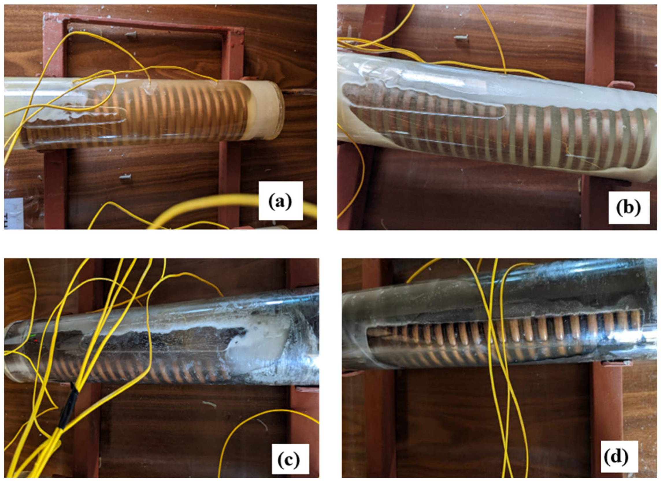
3.1. PCM Fusion in a TES Container

HTF flows in an HTT, exchanges heat with PCM encompassing it and melts subsequently. The melted PCM, with less density than solid PCM, rises to the container’s top. This movement of the superheated liquid PCM exchanges heat with the solid PCM near it and there is concomitant melting. The less dense liquid PCM rises to the top, and the denser solid PCM settles near the bottom, creating natural convection. PCM melting is influenced by natural convection, which leads to more heat exchange and melting. Since the container is placed horizontally and a helical HTT is used, a heat transfer surface is available near the top and bottom, leading to effective melting. Solid PCM settling during melting is reduced due to the heating surface near the bottom. The effective heating from the top and bottom led to a melting expedition. The solidification is carried out after melting. The HTF at 27 °C is used for solidification. After melting, the PCM is in a superheated state, with a significant temperature difference between PCM and HTF (27 °C). This considerable temperature difference effectively transfers heat as per the second law of thermodynamics. This leads to the encircling of solidified PCM around the HTT, affecting further solidification due to PCM’s lower thermal conductivity.
However, the heating surface is present near the top and bottom; hence, less-dense liquid PCM segregation near the top is avoided. During solidification, since liquid PCM, having less density, accumulates near top, a heating surface near the top reduces segregation and solidifies the PCM swiftly. Solidification occurs due to the natural convection at the start and conduction initiates later and prolongs till complete fusion. PCM has less thermal conductivity but the heat surface at the top and bottom expedites the fusion process. Figure 2 shows the melting process. This experiment is performed for four cases (cases 1, 2, 3, and 4) to analyze PCM fusion in a TES container. Case 1 possesses low heat transfer ability; hence, the overall fusion is affected. The PCM melts near the HTT and spreads throughout the container until complete melting. The overall fusion time has increased since PCM suffers from poor thermal conductivity. In case 2, the steatite possesses more thermal conductivity than wax. This leads to less melt time for case 2 compared to case 1. Adding steatite may hinder natural convection, but steatite thermal conductivity overcomes this effect and increases PCM melting. During solidification, heat transfer is influenced by conduction, and hence, the addition of these nanoparticles serves as heat transfer network paths, enhances solidification, and results in less overall fusion time for case 2 than for case 1. For case 3, the CuO nanoparticle is added with PCM. CuO possesses more thermal conductivity; hence, its addition increases heat exchange, resulting in more fusion. While melting, though adding nanoparticles slightly reduces natural convection, the CuO thermal conductivity overcomes this effect and enhances the fusion process. During solidification, since it is influenced by conduction, the nanoparticle addition enhances heat transfer network paths to expedite fusion. Hence, the overall fusion is expedited in case 3 more than in cases 1 and 2 due to CuO. For case 4, possessing a mixture of steatite and CuO, the overall fusion time is less than that in case 2. This is primarily due to enhanced thermal conductivity and heat transfer. During melting, case 3 takes less time to melt completely. Solidification is expedited due to a cumulative increase in thermal conductivity due to adding CuO. The overall fusion time is less for case 3 than that of others due to the fusion expedition.

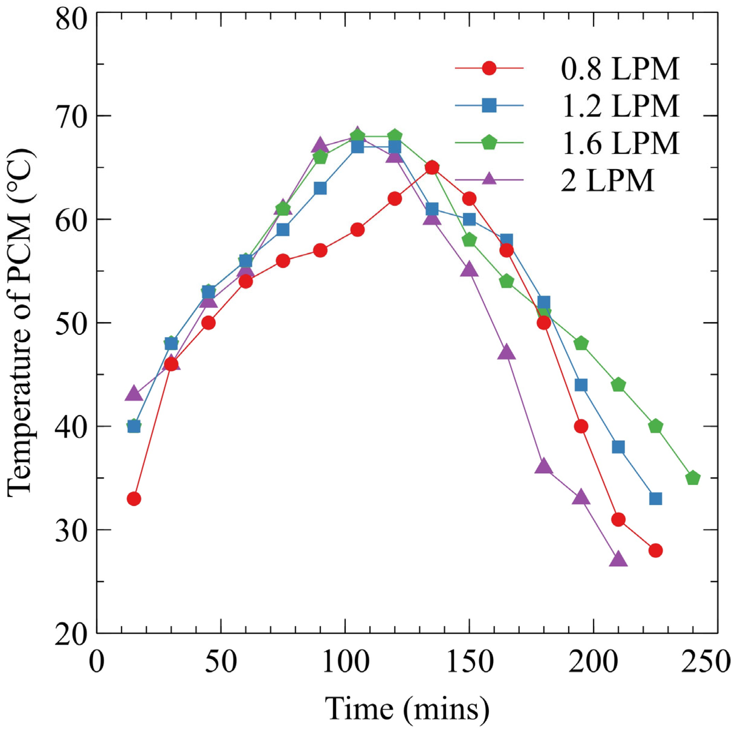
3.2. Effect of Flow Rate on PCM Fusion

The HTF at 70 °C enters the TES container to melt PCM. The HTF flow rate influences PCM fusion in a horizontal TES container. The increase in flow rate enhances heat transfer from HTF to the PCM. The fusion is analyzed for different flowrates, namely, 0.8, 1.2, 1.6, and 2 LPM, respectively, and effective flow rate is identified for further analysis. It is carried out for PCM. Initially, a flow rate of 0.8 LPM is used for this study. It results in melting near the helical HTT, and further melting advancement is achieved through natural convection. The PCM temperature after 30 min is 46 °C, indicating effective melting. The complete melting occurs at 135 min. The analysis is also carried out for solidification. The flow rate increases solidification near the HTT, and further solidification, though hindered, is overcome due to the HTT near the top and bottom. The PCM temperature after 30 min of solidification is 57 °C. Complete solidification occurs at 90 min. The overall fusion time for this configuration is 225 min. Figure 3 shows the effect of HTF flow rate on charging PCM.
Further, the increase in flow rate to 1.2 LPM did not cause any change in complete fusion duration. After 30 min of melting, the PCM temperature is 48 °C, and it is 60 °C for solidification, indicating effective fusion. The flow rate of 1.2 LPM completes PCM fusion at 225 min. The increased flow rate to 1.6 LPM increases fusion time due to more turbulence and less heat transfer. The rise in turbulence reduces heat transfer sites for exchanging heat. After 30 min of fusion, the temperature is 48 °C for melting and 58 °C during solidification. The 1.6 LPM completes fusion at 240 min. The flow rate of 2 LPM is found optimal since complete fusion occurs at 210 min. The fusion temperature after 30 min is 49 °C for melting and 58 °C during solidification. Although there is an increase in turbulence, it is optimal for enhancing fusion. The increase in turbulence, in this case, is favorable for more heat transport. Hence, 2 LPM is considered for further analysis since it expedites PCM fusion.

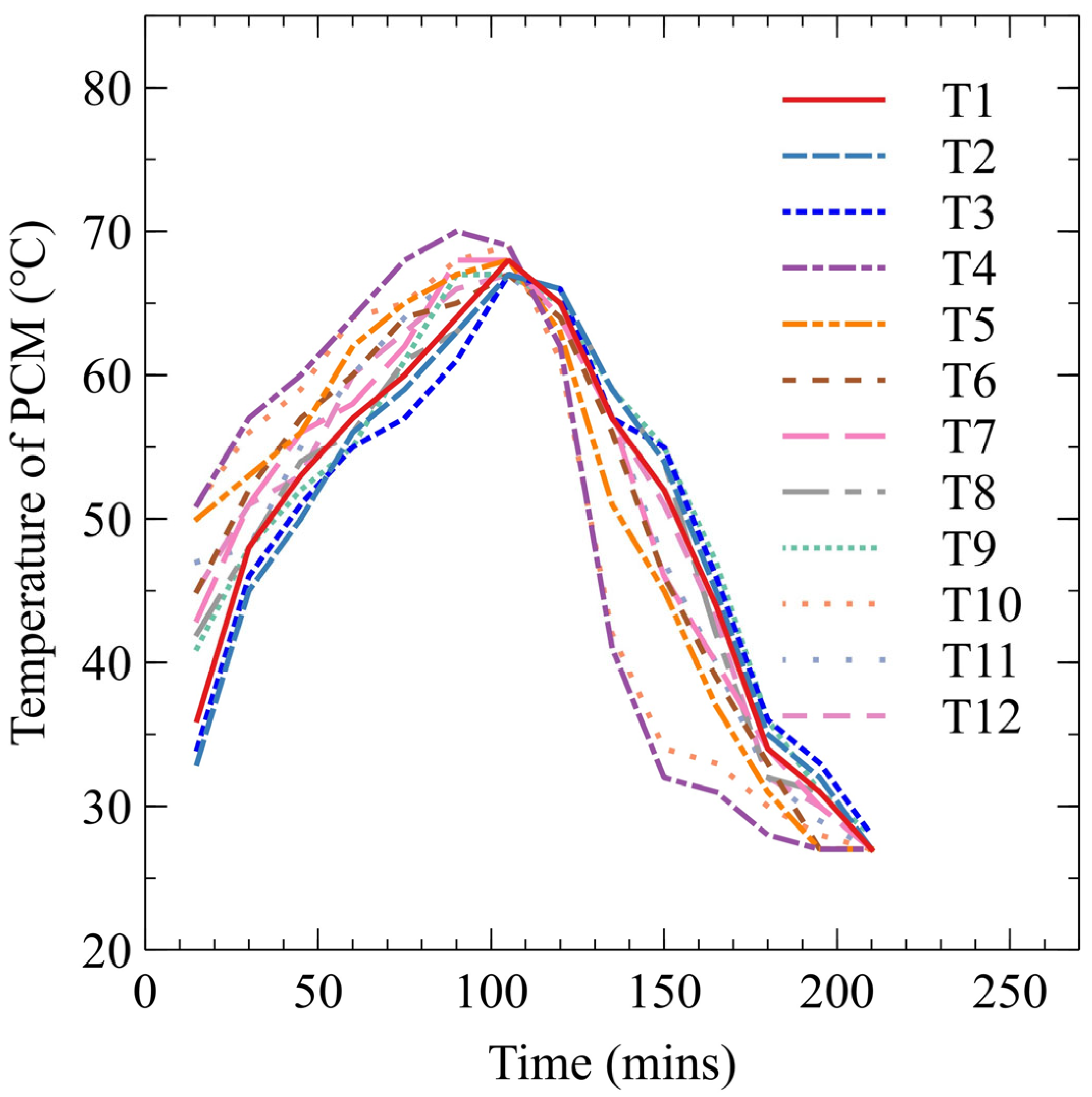
3.3. Effect of HTF Temperature

The HTF at 70 °C and 2 LPM flows through the helical HTT to melt the PCM. Steatite has a thermal conductivity of 3.107 W/m.K, which is higher than that of wax; hence, its addition enhances PCM heat transfer. The thermal conductivity of CuO is 33 W/m.K, which is much higher than that of wax, leading to more heat transfer and effective melting. The high temperature of HTF transfers heat to PCM at a low temperature (27 °C), leading to its melting. The melted PCM becomes superheated and further melts nearby solid PCM, and there is concomitant melting in the TES container. The melted PCM encompasses the HTT and rises to the top due to less density. Solid PCM settling (higher density) results in natural convection for effective melting. Since the heating surface is at the top and bottom, melting is expedited. HTF at 27 °C flows through the HTT and PCM solidifies around the tube during solidification. Initial solidification is with natural convection followed by prolonged conduction. The heating surface presence near the top and bottom expedites solidification. The high-density solid PCM settles near the bottom and encompasses the HTT, hindering heat transfer and further solidification. However, the heating surface near the top and throughout the container expedites solidification. The liquid PCM with less density accumulates near the top. The presence of a heat transfer area near the top absorbs heat from superheated liquid PCM and converts it to solid PCM. The process continues until complete solidification.
The TES container with PCM was initially considered for this study. HTF at 70 °C flowing through the helical coil HTT was initially considered for melting. Once the melting was completed, solidification was carried out at 27 °C. During charging, PCM melts around the HTT due to considerable temperature difference. The melted PCM travels to the top and melts nearby solid PCM. There is a concomitant melting in TES. PCM melting occurs near the top and bottom, expediting melting. Once complete melting is achieved, solidification is carried out immediately. During solidification, solid PCM forms around the helical HTT. Solid PCM formed around the top HTT settles with superheated liquid PCM accumulating near the top. However, the liquid PCM is also solidified due to the heating surface near the top. Hence, solidification is expedited. Paraffin wax has less thermal conductivity; therefore, to address this issue, thermal conductivity additives are added to enhance heat transfer.
Paraffin wax is added with steatite (case 2) to analyze its heat transferability for effective and faster charging. Steatite has higher thermal conductivity than paraffin wax; hence, its addition enhances heat transfer during the charging of HTF at 70 °C, which flows through a helical HTT. Steatites have higher thermal conductivity than paraffin wax, resulting in more heat transport and melting. The significant temperature difference and improved thermal conductivity from steatite addition in paraffin wax expedite the PCM melting process. Initially, heat is transferred to PCM through conduction, resulting in more melting around the HTT. The liquid PCM becomes superheated along with steatite, further enhancing heat transfer. Steatite creates an active place for effective heat transfer; hence, melting is more expedited in this configuration than paraffin wax. Forming liquid PCM takes a shorter duration than paraffin wax in this case. Solid PCM turns to liquid quickly due to steatite presence. Solidification is conducted once complete melting is achieved. Conduction is dominant during solidification, and steatite addition leads to more solidification due to active conduction. The heat transfer occurs through steatite, with heat transfer paths for adequate solidification. PCM fusion occurs near the HTT initially, and solidification is expedited with steatite possessing active heat transfer paths. The presence of a heating surface near the top and bottom with steatite added to PCM led to an overall fusion expedition. Hence, case 2 (with steatite) is found to have more fusion than case 1 due to more heat transport.
This study was performed on paraffin wax with CuO in a TES container (case 3). CuO possesses higher thermal conductivity than paraffin wax and hence its addition enhances PCM heat transferability. The high-temperature HTF flows through the helical HTT and melts the PCM near it. The melted PCM with CuO encompasses the HTT. This superheated liquid PCM exchanges heat with near-solid PCM, leading to more melting. This liquid PCM rises to the top and melts solid PCM before reaching the top. The container top has a heating area leading to further liquid PCM formation and associated PCM melting. The PCM melting is expedited by natural convection. CuO nanoparticles with high thermal conductivity enhance heat transfer and expedite PCM melting. CuO provides active sites for heat transfer. The heat transfer in PCM with CuO increases abruptly due to network paths for heat transfer, resulting in a melting expedition in case 3. Solidification is carried out immediately after melting. During solidification, HTF at low-temperature flows through the HTT, solidifying PCM near the HTT. Though solidified PCM might act as a barrier in further heat transfer, the presence of CuO reduces this effect due to its enhanced heat transfer ability. More heat transfer occurs through solid PCM with CuO-enhanced solidification. The solidified PCM leads to liquid PCM near the top, but the helical HTT near the top leads to further solidification. The overall fusion is completed faster due to CuO. The thermal conductivity enhancement leading to more heat transfer results in more fusion in case 3 than in cases 1 and 2.
This study used a steatite and CuO mixture in wax (case 4). Both possess more thermal conductivity than paraffin wax, which leads to PCM fusion expedition. During melting, HTF at high-temperature flows through the helical HTT. The melted PCM encompasses the helical HTT at the top and bottom of the TES container. Liquid PCM starts forming at the top and bottom, and concomitant melting occurs in the TES container. Solid PCM ascends, and the liquid PCM descends due to a density difference, leading to natural convection and enhanced melting. The presence of steatite and CuO causes a synergic effect in improving heat transfer and expediting melting in case 4. Once complete melting is achieved, solidification is carried out. The HTF flowing through the HTT at low temperatures absorbs heat from PCM. It leads to more solidified PCM around the helical HTT. Solidification is influenced by conduction. CuO and steatite provide more active heat transfer paths for adequate solidification in case 4. Though solidified PCM forming around the HTT may hinder heat transfer, the presence of thermally conductive nanoparticles reduces this effect. It increases heat transfer and forms more solidified PCM, leading to fusion expeditions. The solidified PCM forms near the top, bottom, and liquid PCM accumulates in the middle briefly. This effect is reduced due to the presence of nanoparticles. The overall fusion duration is reduced in case 4 compared to others due to synergic heat transfer. Figure 4 indicates PCM temperature variation during this study. The temperature variation near the inlet, middle, and outlet for four cases—case 1 (T1, T2, and T3), case 2 (T4, T5, and T6), case 3 (T7, T8, and T9), and case 4 (T10, T11, and T12)—are studied. From Figure 4, the steepness in the curve for T1, T2, and T3 for case 1 is less than that of the others. It indicates less heat transfer in case 1.
After 45 min of melting, the temperature is 53 °C for T1 and 51 and 50 °C for T2 and T3. During solidification, the temperature after 45 min is 52, 54, and 55 °C. For case 2 at the same instant, the temperatures are 56, 54, and 52 °C for T4, T5, and T6, respectively, during melting and 46, 54, and 55 °C during solidification. There is an increase and decrease in temperature during melting and solidification. There is a 5.6, 5.8, and 10% increase in temperature in case 2 compared to case 1 during melting and an 11.5% decrease in temperature during solidification due to the enhanced thermal conductivity of steatite. Hence, the overall fusion is expedited in case 2 more than in case 1. For case 3 at 45 min, the temperatures T7, T8, and T9 are 60, 56, and 57 °C during melting and 32, 45, and 46 °C during solidification. There is an increase and decrease in temperature during melting and solidification. Hence, melting and solidification are expedited in case 3 compared to case 1 and case 2. The fusion expedition in case 3, compared to cases 1 and 2, is due to CuO’s greater thermal conductivity.
During melting, 13.2, 9.8, and 14% increases in temperature are found in case 3 compared to case 1, and during solidification, 38.46, 16.6, and 16.36% decreases are found. For case 4, temperatures T10, T11, and T12 during melting and solidification are 59, 55, and 53 °C and 34, 47, and 51 °C, respectively. The percentage increase and decrease in temperature during melting and solidification are 11.3, 7.8, and 6% and 34.6, 12.9, and 7.27%, respectively, indicating case 4 is more effective than cases 1 and 2. From this study, case 3 is found to have a higher increase in temperature than other cases when compared with case 1; hence, fusion is expedited in case 3. The primary reason behind the temperature rise is due to the enhanced thermal conductivity of CuO rather than steatite. Case 4 is a mix of CuO and steatite resulting in reduced heat transfer compared to case 3 due to steatite’s lower thermal conductivity compared to CuO.

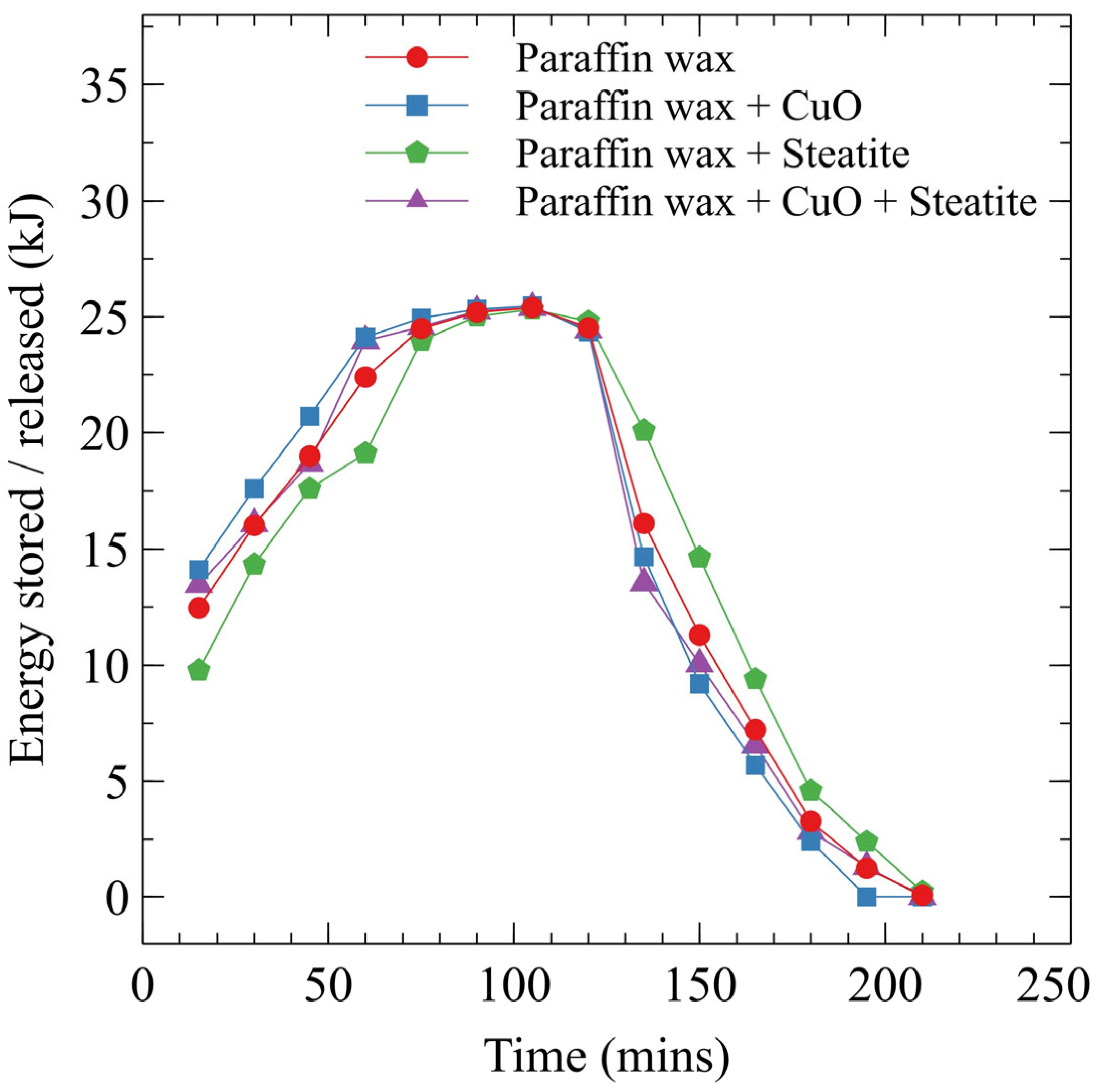
3.4. Energy Stored and Released

HTF at high-temperature melts PCM near the HTT circumference. Initially, sensible heat is added, and latent heat is added after melting. Sensible heat is less than latent heat, which has led to its use in many applications. The heat stored in PCM possesses three stages: initial sensible heat, latent heat during melting, and final sensible heat, respectively. The heat stored depends on the PCM’s mass and the melting of the PCM in the TES container. More melting leads to more heat storage due to sensible and latent heat. LHS occurs near isothermal phase change, so a large amount of heat is stored. In case 1, where no additives are added to PCM, the latent heat remains high. The energy stored increases during melting for paraffin wax filled in a TES container. As more PCM melts, more heat storage occurs; hence, maximum heat is stored at the end of melting. Solidification carried out after melting is used for the absorption of heat from PCM. The heat from PCM is transferred to HTF at low temperatures, and there is a release of heat from PCM. Initially, sensible heat is absorbed by HTF, and latent heat is exchanged as more PCM solidifies. More solidification leads to more latent heat release by PCM.
Solidification occurs at the top and bottom; heat exchange occurs at both locations. Once PCM is completely solidified, the total heat absorbed by PCM is released to HTF. The amount of heat stored/released is more for case 1 due to the absence of additives. This study is further extended to using paraffin wax with steatite nanoparticles. Adding nanoparticles enhances thermal conductivity but reduces PCM’s heat storage capacity. Hence, in case 2, the heat stored is slightly less than in case 1. The fusion process remains the same; however, the time to establish fusion is shorter due to enhanced heat transfer. Initial melting leads to heat storage due to sensible and latent heat, and further temperature increases raise sensible heat. The rise in heat storage is steep due to effective heat transfer and more melting. Heat storage is followed by release, and HTF releases heat faster than wax. Though heat storage/release is faster in case 2 than in case 1, the amount of heat is less due to additives in case 2. Figure 5 indicates energy stored/released during fusion for all cases.
In case 3, the paraffin wax is mixed with CuO nanoparticles to analyze the TES system’s energy storage/release ability. The energy storage is less in this case than in the first case (paraffin wax) due to there being less wax, even though less time is taken for complete heat storage and release. During storage, the wax with CuO stores/release heat rapidly. Since the number of nanoparticles is the same in both cases (cases 2 and 3), the energy stored/released is the same. Finally, this study is carried out for paraffin wax with an equal proportion of CuO and steatite nanoparticles. Adding these two nanoparticles enhances fusion, but they do not take part in fusion; hence, there is a decrease in the energy stored/released compared to case 1 (paraffin wax). The trend remains the same for all the cases. The heat stored/released would have been more for case 1 than the other cases due to there being more wax in case 1, but the long fusion duration resulted in heat loss in case 1. The steepness in the curve is more significant for case 3 than the others due to effective heat transfer leading to more storage/release. At 45 min, the heat stored and released for case 1 measures 15.86 and 17.52 kJ, respectively. For case 2, it measures 17.6, and 14.64 kJ. There is a 10.9 increase and 16.4% decrease in the heat stored and released. The reduction in heat release indicates a solidification expedition. For case 3, the heat stored and released measures 20.71 and 9.2 kJ. There is an increase in heat storage and a decrease in heat release of 30.5 and 47.4% in case 3 compared to case 1. The increase in heat storage indicates a melting expedition. For case 4, the heat stored and released is 18.69 and 10.05 kJ. There is a 17.8% increase in the heat stored and a 42.6% decrease in the heat released in case 4 compared to case 1. The results show an increase in heat storage for case 3 compared to others, indicating that case 3 is effective in PCM fusion primarily due to enhanced heat transfer compared to case 1.

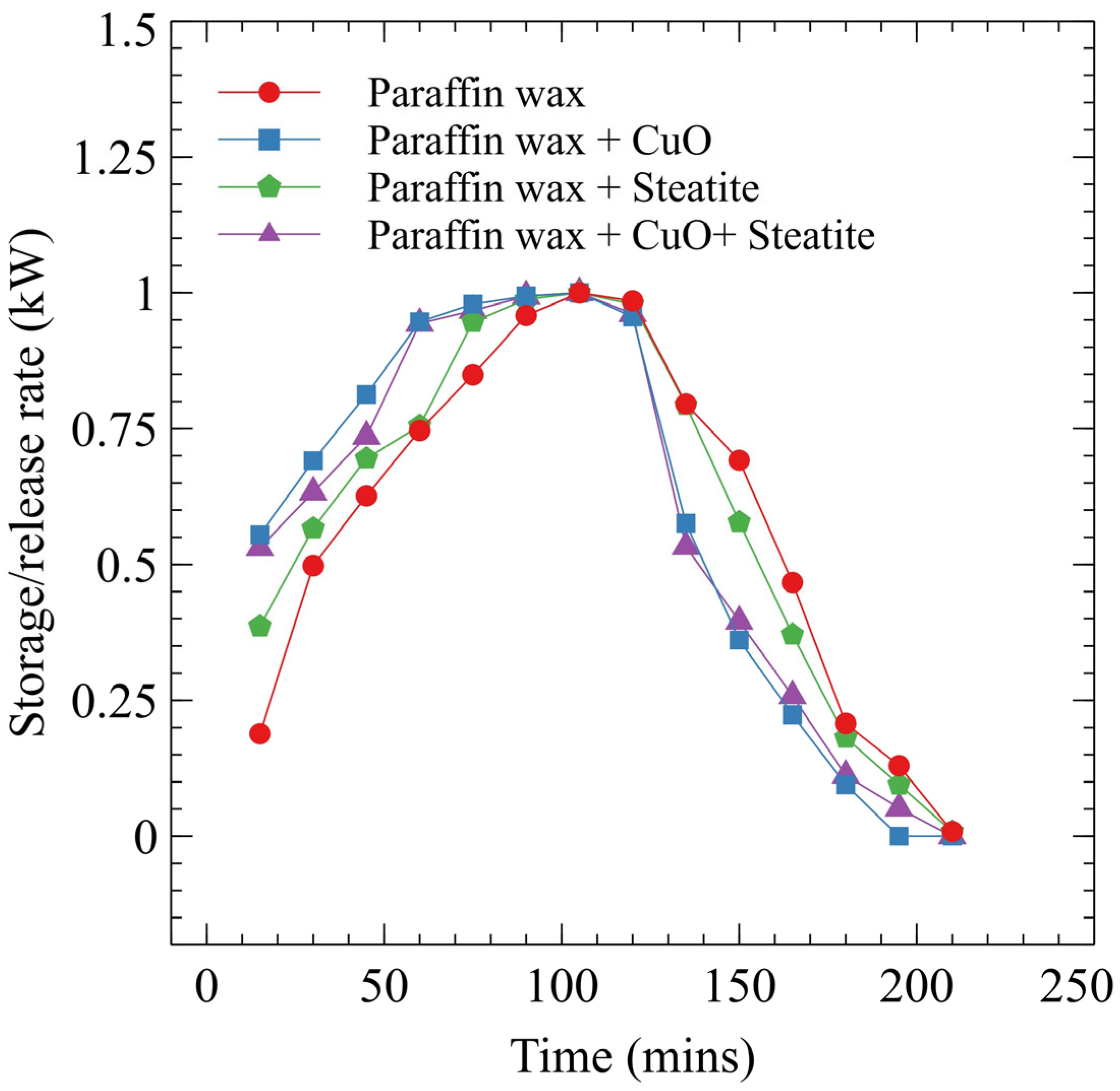
3.5. Energy Storage/Release Rate

This study was carried out to analyze the energy storage/release rate in a TES container. The enhanced storage/release rate is required for many applications in TES systems. Initially, the experiment conducted using case 1 displayed a higher storage rate. HTF at elevated temperatures exchanges heat with PCM at low temperatures, so the energy storage rate is high at the start. The heat absorbed from the HTF melts more PCM near the helical HTT. This superheated PCM melts more solid PCM, and complete melting is achieved. The heat storage rate is high initially and declines as more melted PCM forms inside the TES container. As more melting occurs, the heat required for further melting is less; hence, the heat storage rate decreases. During heat release, heat flows from high-temperature PCM to low-temperature HTF. Initially, the temperature will be high due to the availability of more liquid PCM. Once solidified PCM accumulates, the heat release rate decreases due to the unavailability of heat for further release. Figure 6 shows the rate of heat storage and release.
In case 1, wax with low thermal conductivity starts melting around the HTT. The storage rate is high as more PCM absorbs heat and starts melting. PCM melting occurs throughout the container due to natural convection and the HTT at the top and bottom in a horizontal TES container. Once the PCM melts more, the storage rate decreases since less solid PCM is available to melt. Once the melting is completed, solidification starts. The heat release rate during solidification is high at the initial stages due to higher PCM temperatures. The formation of more solidified PCM around the HTT hinders heat transfer and decreases the heat release rate. The decrease in heat release rate is attributed to more solidified PCM in a TES container. The analysis is carried out for paraffin wax with steatite nanoparticles in case 2. Adding nanoparticles enhances heat transfer, and the heat storage/release rate is higher in this case than in case 1.
Initial melting is high due to the presence of steatite in wax. This leads to melting expedition and an enhanced storage rate. Due to the melting expedition, the storage rate reduces within a shorter duration because more melting occurs and there is less solid PCM for melting. Melting occurs both from the top and bottom of the container since the HTT is present at these locations. Once solidification is initiated, a more solidified PCM will be formed around the HTT. Though PCM hinders further solidification, the presence of steatite enhances heat transfer due to heat network paths. Hence, solidification is more expedited in this case than in case 1. Case 3 is studied using paraffin wax and CuO nanoparticles. This nanoparticle has higher thermal conductivity than cases 1 and 2. Hence, heat transfer is high in this case. The heat storage rate is high due to nanoparticle additives in PCM. Melting occurs near the HTT, and the presence of CuO enhances PCM fusion. This leads to a higher energy storage rate. The initial heat storage rate is higher in this case than others (cases 1, 2, and 3), leading to more melting. Melting is initiated both at the top and near the bottom, and the energy storage rate decreases rapidly due to quick melting. During solidification, energy release occurs from PCM with CuO to HTF at low temperatures. CuO nanoparticles serve as active sites for heat transfer and expedite energy release. It leads to a higher release rate at the start. However, this is short-lived due to more solidified PCM in the TES container.
Case 4, with paraffin wax mixed with CuO and steatite, is used for analyzing energy storage/release rate. The presence of CuO and steatite enhances PCM heat transfer and increases the storage rate. The storage rate decreases rapidly due to more melting as less solid PCM is available in the TES container. The release rate is analyzed after melting. The presence of CuO and steatite mixture increases the heat release rate. The heat storage and release rate for case 1 at 45 min is 0.593 and 0.697 kW. For case 2, it is 0.523 and 0.588 kW. There is a decrease of 11.8 and 15.6% in heat storage and release rates. It indicates more fusion occurred each time, leading to a lower storage/release rate. The storage/release rate for case 3 is 0.506 and 0.667 kW. There is a 14.6 and 4.3% decrease in case 3 than in case 1. The values for case 3 are much lower, indicating a fusion expedition. For case 4, it is 0.514 and 0.593 kW. There is a decrease of 13.32% and 14.92% in the heat storage and release rates. From this analysis, the storage/release rate decrease is more significant for case 3; hence, case 3 can be suggested for more solar thermal applications. An experiment is then conducted for case 2 with steatite added to paraffin wax. Since steatite is added to PCM, the latent heat decreases. The overall heat storage decreases in this case compared to case 1. However, heat transfer is enhanced due to steatite, and heat storage is expedited. The effectiveness increases slightly compared to case 1 due to melting expedition and increased storage. The increase in effectiveness is due to increased melting in the container’s top and bottom, along with steatite presence. Heat release effectiveness rises steadily, but the rate at which release occurs is higher than in case 1.

3.6. Heat Storage Effectiveness

Heat storage effectiveness is the ratio of energy stored/released to the maximum energy stored/released. Analysis is conducted for all four cases (cases 1, 2, 3, and 4). Case 1 (paraffin wax) is analyzed for effectiveness. The maximum energy storage occurs during complete PCM melting. For case 1, paraffin wax is used as PCM, and melting occurs due to heat transfer. The effectiveness increases with time and attains maximum effectiveness once complete melting is achieved. During solidification, heat release occurs. Since PCM possesses poor thermal conductivity, heat release occurs slowly. The effectiveness during melting and solidification is lower for paraffin wax since it retains less heat transfer ability, leading to more fusion time. Figure 7 illustrates the effectiveness of heat storage by PCM. Another experiment is then conducted for case 3 (PCM and CuO). The heat storage/release effectiveness tends to increase in this case as the TES is enhanced. The nanoparticles enhance heat transfer and effectiveness. During storage, effectiveness increases until complete melting. The maximum effectiveness is achieved after all the PCM melts in the TES container. Since melting occurs at the top and bottom due to enhanced heat transfer, effectiveness is increased. During heat release, PCM solidifies near the top and bottom, and effectiveness reduces to the lowest value after complete solidification. The effectiveness is higher in this case than in cases 1 and 2. Another experiment is further conducted for case 4. The effectiveness is higher during storage than in other cases due to enhanced heat transfer. Due to simultaneous melting in the TES container, the effectiveness of case 4 is higher than that of case 2.
The solidification expedition results in improved effectiveness and hence increases overall fusion. The heat storage and release effectiveness for case 1 at 45 min is 0.626 and 0.691. For case 2, it is 0.694 and 0.577. There is an increase of 9.7% in storage effectiveness and a decrease of 16.49% in release effectiveness, primarily due to enhanced fusion. For case 3, it is 0.812 and 0.360. There is an increase of 29.7% in storage effectiveness and a decrease of 47.9% in effectiveness for case 3. Case 3 displays enhanced effectiveness due to improved heat transfer. For case 4, it is 0.735 and 0.395. There is an increase of 17.41 in the storage effectiveness and a decrease of 42.83% in the release effectiveness. From the experimental study, case 3 is found to have increased effectiveness; hence, the inclusion of CuO is efficacious in improving PCM fusion and suitable for domestic solar water heaters and heat recovery applications.
The upper limits of CuO (5 wt%) and steatite (10 wt%) were chosen based on the literature to study heat transfer performance while addressing risks like agglomeration and sedimentation. These nanocomposites enhanced thermal performance in paraffin wax-based LHS systems. However, this study has limitations, including limited experimental configurations (four cases), potential latent heat capacity changes, lack of long-term stability data, and economic viability for large-scale applications. Lower additive concentrations could reduce system complexity and cost. Higher concentrations often cause agglomeration, sedimentation, and increased viscosity, complicating manufacturing and requiring additional steps (e.g., sonication) for proper dispersion [53,54,55]. Lower concentrations minimize these issues, simplifying production and maintenance while reducing material costs for improved economic feasibility in large-scale TES applications.

4. Conclusions

This experimental study investigated the process of nanocomposite PCM fusion in a TES container. The significant findings highlight the influence of several factors such as heat transfer rates, PCM phase change characteristics, additive percentage, and effectiveness of storage in the fusion process. The significant findings are as follows.
  • PCM melts around an HTT, facilitated by heat exchange with a high-temperature HTF. The less dense melted PCM rises to the container’s top, exchanging heat with solid PCM and further promoting melting through natural convection.
  • Nanocomposites with steatite and CuO enhanced thermal conductivity and expedited PCM fusion. Steatite increased PCM melting by reducing solid PCM settlement, while CuO facilitated faster heat exchange and melting despite having minor impacts on natural convection.
  • During solidification, the PCM temperature drops as HTF at 27 °C flows through the HTT. This creates a significant temperature difference, aiding in solidification as per the second law of thermodynamics. The presence of heat transfer surfaces at both the top and bottom accelerates solidification despite PCM’s low thermal conductivity.
  • Case 3 utilizes a blend of paraffin wax and CuO, demonstrates superior heat transfer capabilities, and achieves the fastest overall fusion time of 90 min, highlighting its potential for efficient TES applications.
  • The flow rate of the HTF significantly influences PCM fusion in the horizontal TES system. Optimal fusion was observed at 2 LPM, where increased turbulence enhanced heat transport efficiency despite challenges at higher flow rates that reduced heat exchange efficiency.
  • The HTF inlet temperature of 70 °C proved effective in melting PCM, with steatite and CuO additives further enhancing heat transfer. Their inclusion facilitated faster PCM melting and solidification, improving overall system efficiency.
  • The energy stored and released for case 3 is 20.71 and 9.2 kJ. There is an increase of 30.5% in heat storage and a decrease of 47.4% in heat release in case 3 compared to case 1. This indicates case 3 is effective in expediting fusion.
  • The storage and release rate for case 3 is 0.506 and 0.667 kW. A 14.6 and 4.3% decrease in the storage and release rate is seen in case 3 compared to case 1.
  • The energy effectiveness for case 3 is 0.812 and 0.360. There is an increase of 29.7% and a decrease of 47.9% in effectiveness found in case 3. It displayed enhanced effectiveness due to improved heat transfer.
  • Cases with nanocomposite additives showed varied energy storage capacities, with enhanced thermal conductivity leading to quicker heat storage and release cycles.
  • Cases incorporating nanocomposites exhibited accelerated rates due to improved heat transfer efficiency, influencing the overall effectiveness of PCM fusion.
  • Configurations with nanocomposites demonstrated higher effectiveness, particularly in facilitating rapid PCM fusion and efficient heat transfer during storage and release cycles.
The findings emphasize the potential of nanocomposite-enhanced PCM systems for optimizing TES performance in diverse applications and their practical viability in real-world scenarios. Future research should focus on improving nanocomposites’ thermal conductivity and stability, exploring cost-effective materials, and further investigating long-term performance under varying environmental conditions to enhance TES systems’ efficiency, reliability, and adaptability. Further, the nanoparticle concentration (10 wt%) increases viscosity; hence, this nanoparticle dispersion study improves applicability in real-world systems. However, this study has limitations in terms of sensor calibration, inconsistency in nanoparticle dispersion, and heat loss to the surroundings, affecting thermal conductivity and phase change. Further, NePCM stability must be studied for multiple fusion cycles.
Future research should prioritize lower additive concentrations to balance thermal performance and cost effectiveness. This includes identifying the minimum effective concentration of CuO and steatite that enhances thermal conductivity and heat transfer without reducing the latent heat capacity of paraffin wax. Additionally, studies should assess the long-term stability of nanocomposite PCMs under repeated thermal cycling to ensure durability and reliability. A detailed cost–benefit analysis is also crucial to evaluate economic viability for widespread adoption in solar energy storage, building heating/cooling, and industrial waste heat recovery. Addressing these aspects can lead to more efficient, scalable, and sustainable latent heat-based TES systems.

Author Contributions

Conceptualization, J.P., C.S. and R.S.; Methodology, J.P., C.S. and R.S.; Validation, C.S. and R.S.; Formal analysis, J.P., S.B.M.P. and C.S.; Investigation, J.P., S.B.M.P., C.S. and R.S.; Writing—original draft, J.P. and S.B.M.P.; Writing—review & editing, C.S. and R.S.; Visualization, S.B.M.P. All authors have read and agreed to the published version of the manuscript.

Funding

This research received no external funding.

Institutional Review Board Statement

Not applicable.

Informed Consent Statement

Not applicable.

Data Availability Statement

Data will be made available on request.

Acknowledgments

The authors acknowledge the Nanotechnology Research Centre (NRC), SRM Institute of Science and Technology (SRMIST), Chennai, India, for providing the required research facilities for material characterization. They also thank the Thermal Energy Storage Research Cell, Department of Mechanical Engineering, SRMIST, Chennai, India, for providing the research facilities for experimentation.

Conflicts of Interest

The authors declare no conflicts of interest.

Abbreviations

GOGraphene oxide
CuOCopper oxide
HTFHeat transfer fluid
HTTHeat transfer tube
LHSLatent heat storage
MWCNTMultiwall carbon nanotube
NePCMNano-enhanced phase change material
PCMPhase change material
PEGPolyethylene glycol
TESThermal energy storage

References

  1. Martins, T.; Barreto, A.C.; Souza, F.M.; Souza, A.M. Fossil fuels consumption and carbon dioxide emissions in G7 countries: Empirical evidence from ARDL bounds testing approach. Environ. Pollut. 2021, 291, 118093. [Google Scholar] [CrossRef]
  2. Panwar, N.L.; Kaushik, S.C.; Kothari, S. Role of renewable energy sources in environmental protection: A review. Renew. Sustain. Energy Rev. 2011, 15, 1513–1524. [Google Scholar] [CrossRef]
  3. Tripathi, B.M.; Shukla, S.K.; Rathore, P.K.S. A comprehensive review on solar to thermal energy conversion and storage using phase change materials. J. Energy Storage 2023, 72, 108280. [Google Scholar] [CrossRef]
  4. Jouhara, H.; Żabnieńska-Góra, A.; Khordehgah, N.; Ahmad, D.; Lipinski, T. Latent TES technologies and applications: A review. Int. J. Thermofluids 2020, 5–6, 100039. [Google Scholar] [CrossRef]
  5. Jiang, R.; Qian, G.; Li, Z.; Yu, X.; Lu, Y. Progress and challenges of latent thermal energy storage through external field-dependent heat transfer enhancement methods. Energy 2024, 304, 132101. [Google Scholar] [CrossRef]
  6. Tofani, K.; Tiari, S. Nano-enhanced phase change materials in latent heat thermal energy storage systems: A review. Energies 2021, 14, 3821. [Google Scholar] [CrossRef]
  7. Reji Kumar, R.; Samykano, M.; Pandey, A.K.; Kadirgama, K.; Tyagi, V.V. Phase change materials and nano-enhanced phase change materials for thermal energy storage in photovoltaic thermal systems: A futuristic approach and its technical challenges. Renew. Sustain. Energy Rev. 2020, 133, 110341. [Google Scholar] [CrossRef]
  8. Said, Z.; Pandey, A.K.; Tiwari, A.K.; Kalidasan, B.; Jamil, F.; Thakur, A.K.; Tyagi, V.V.; Sarı, A.; Ali, H.M. Nano-enhanced phase change materials: Fundamentals and applications. Prog. Energy Combust. Sci. 2024, 104, 101162. [Google Scholar] [CrossRef]
  9. Mukhesh, R.; Sarath, K.P.; Feroz Osman, M.; Deepu, M.; Manu, K.V. Asymmetric PCM melting and thermal convection in a rectangular enclosure with straight and wavy heat transfer passages. Int. J. Heat Mass Transfer 2023, 217, 124625. [Google Scholar] [CrossRef]
  10. Punniakodi, B.M.S.; Senthil, R. Recent developments in nano-enhanced phase change materials for solar thermal storage. Sol. Energy Mater. Sol. Cells 2022, 238, 111629. [Google Scholar] [CrossRef]
  11. Thangapandian, E.; Palanisamy, P.; Selvaraj, S.K.; Chadha, U.; Khanna, M. Detailed experimentation and prediction of thermophysical properties in lauric acid-based nanocomposite phase change material using artificial neural network. J. Energy Storage 2023, 74, 109345. [Google Scholar] [CrossRef]
  12. Mishra, G.; Memon, A.; Gupta, A.K.; Nirmalkar, N. Computational study on effect of enclosure shapes on melting characteristics of phase change material around a heated cylinder. Case Stud. Therm. Eng. 2022, 34, 102032. [Google Scholar] [CrossRef]
  13. Talele, V.; Zhao, P. Effect of nano-enhanced phase change material on the thermal management of a 18650 NMC battery pack. J. Energy Storage 2023, 64, 107068. [Google Scholar] [CrossRef]
  14. Patel, P.; Sharma, A.; Monde, A.D.; Sharma, M.; Mondal, B.; Kothadia, H.B. Performance analysis of melting phenomena in an ice-freezing type direct-contact heat exchanger. J. Energy Storage 2022, 50, 104575. [Google Scholar] [CrossRef]
  15. Athawale, V.; Jakhar, A.; Jegatheesan, M.; Rath, P.; Bhattacharya, A. A 3D resolved-geometry model for unstructured and structured packed bed encapsulated phase change material system. J. Energy Storage 2022, 51, 104430. [Google Scholar] [CrossRef]
  16. Teja, P.N.S.; Gugulothu, S.K.; Reddy, P.D.S.; Barmavatu, P. Effect of orientation and nanoparticle addition of an encapsulated phase change material on heat transfer in a packed bed thermal energy storage system—A numerical analysis. J. Energy Storage 2024, 78, 110023. [Google Scholar] [CrossRef]
  17. Das, S.; Athawale, V.; Joy, J.M.; Jegatheesan, M.; Rath, P.; Bhattacharya, A. A 3D pore-scale model for macro-encapsulated phase change material-metal foam hybrid energy storage system. J. Energy Storage 2023, 63, 106995. [Google Scholar] [CrossRef]
  18. Nahak, P.K.; Athawale, V.; Jegatheesan, M.; Rath, P.; Bhattacharya, A. Effect of variable capsule size distribution for unstructured packed bed encapsulated phase change material system. Int. J. Heat Mass Transfer 2022, 197, 123354. [Google Scholar] [CrossRef]
  19. Bharathiraja, R.; Ramkumar, T.; Selvakumar, M. Studies on the thermal characteristics of nano-enhanced paraffin wax phase change material (PCM) for thermal storage applications. J. Energy Storage 2023, 73, 109216. [Google Scholar] [CrossRef]
  20. Kumar, R.; Samykano, M.; Pandey, A.K.; Kadirgama, K.; Tyagi, V.V. A comparative study on thermophysical properties of functionalized and non-functionalized Multi-Walled Carbon Nano Tubes (MWCNTs) enhanced salt hydrate phase change material. Sol. Energy Mater. Sol. Cells 2022, 240, 111697. [Google Scholar] [CrossRef]
  21. Duan, P.; Abed, A.M.; Chaturvedi, R.; Ahmad, S.F.; Absalamov, T.; Dahari, M.; Fouad, Y. Heat absorption/release efficiency betterment of phase change material inside a shell-and-tube latent heat storage system under six different conditions of tube and fins. J. Energy Storage 2024, 90, 111880. [Google Scholar] [CrossRef]
  22. Punniakodi, B.M.S.; Senthil, R. Enhanced heat transfer in a phase change energy storage with helical tubes. J. Energy Storage 2023, 58, 106352. [Google Scholar] [CrossRef]
  23. Chatterjee, S.; Bhanja, D.; Nath, S. Numerical investigation of heat transfer and melting process of phase change material in trapezoidal cavities with different shapes and different heated tube positions. J. Energy Storage 2023, 72, 108285. [Google Scholar] [CrossRef]
  24. Senthil, R.; Cheralathan, M. Simultaneous testing of a parabolic dish concentrated PCM and non-PCM solar receiver. Int. J. Mech. Prod. Eng. Res. Dev. 2017, 7, 79–85. [Google Scholar]
  25. Sutradhar, J.; Kothari, R.; Sahu, S.K. Melting and solidification analysis of phase change material-metal foam composite with expansion/shrinkage void in rectangular system. J. Energy Storage 2022, 47, 103596. [Google Scholar] [CrossRef]
  26. Jeyaseelan, T.R.; Vigneshwaran, P.; Saboor, S.; Kumar, D.S.; Saxena, K.K.; Arıcı, M. Experimental study on effect of mild steel scrap vertical insert in charging and discharging process of NaNO3:KNO3 phase change material. J. Energy Storage 2024, 85, 111074. [Google Scholar] [CrossRef]
  27. Alqaed, S.; Almehmadi, F.A.; Mustafa, J.; Husain, S.; Cheraghian, G. Effect of nano phase change materials on the cooling process of a triangular lithium battery pack. J. Energy Storage 2022, 51, 104326. [Google Scholar] [CrossRef]
  28. Rajeswari, K.; Hari Suthan, V.; Suganthi, K.S.; Thiruvenkatam, S.; Devaraj, S.; Rajan, K.S. Graphene oxide–adipic acid nanocomposites for thermal energy storage: Assessment of thermophysical properties and energy storage performance. J. Energy Storage 2024, 77, 109949. [Google Scholar] [CrossRef]
  29. Bharathiraja, R.; Ramkumar, T.; Karthick, L.; Mohanraj, M. Performance investigation on flat plate solar water collector using a hybrid nano-enhanced phase change material (PCM). J. Energy Storage 2024, 86, 111163. [Google Scholar] [CrossRef]
  30. Chandrasekaran, P.; Premnath, D.; Cheralathan, M.; Senthil, R. Experimental thermal performance of deionized water and iron oxide nanofluid for cold thermal storage. Environ. Sci. Pollut. Res. 2024, 31, 26330–26339. [Google Scholar] [CrossRef]
  31. Kumar, A.; Saha, S.K.; Kumar, K.R.; Rakshit, D. Study of melting of paraffin dispersed with copper nanoparticles in square cavity subjected to external magnetic field. J. Energy Storage 2022, 50, 104338. [Google Scholar] [CrossRef]
  32. Selvaraj, V.; Krishnan, H. Acidic functionalized graphene dispersed polyethylene glycol nano-phase change material for the active cooling of a simulated heat-generating electronic system. J. Energy Storage 2022, 45, 103774. [Google Scholar] [CrossRef]
  33. Saranprabhu, M.K.; Rajan, K.S. Thermal energy storage system with a high-temperature nanoparticle enhanced phase change material: Charging and discharging characteristics upon integration with process preheating. J. Energy Storage 2022, 55, 105295. [Google Scholar] [CrossRef]
  34. Bharathiraja, R.; Ramkumar, T.; Selvakumar, M.; Radhika, N. Thermal characteristics enhancement of paraffin wax phase change material (PCM) for thermal storage applications. Renew. Energy 2024, 222, 119986. [Google Scholar] [CrossRef]
  35. Kushwaha, P.K.; Sharma, N.K.; Kumar, A.; Meena, C.S. Recent advancements in augmentation of solar water heaters using nanocomposites with PCM: Past, present, and future. Buildings 2023, 13, 79. [Google Scholar] [CrossRef]
  36. Paul, J.; Samykano, M.; Pandey, A.K.; Kadirgama, K.; Tyagi, V.V. Nano-engineered paraffin-based phase change material for building thermal management. Buildings 2023, 13, 900. [Google Scholar] [CrossRef]
  37. Sivashankar, M.; Selvam, C.; Suresh, S. Experimental study on the performance of low concentrated solar photovoltaic system with nano-enhanced phase change material encapsulated heat sink. Appl. Therm. Eng. 2025, 262, 125254. [Google Scholar] [CrossRef]
  38. Venkatraman, S.; Jidhesh, P.; Rathnaraj, J.D.; Selvam, C. Experimental studies on the enhancement in discharging characteristics of phase change material with steatite nanoparticles. J. Energy Storage 2023, 73, 109103. [Google Scholar] [CrossRef]
  39. Brychka, S.; Brychka, A.; Hedin, N.; Mondeshki, M. Sustainable composite materials based on carnauba wax and montmorillonite nanoclay for energy storage. Materials 2024, 17, 1978. [Google Scholar] [CrossRef]
  40. Vijay Krishna, N.; Manikandan, S.; Selvam, C. Enhanced performance of thermoelectric cooler with phase change materials: An experimental study. Appl. Therm. Eng. 2022, 212, 118612. [Google Scholar] [CrossRef]
  41. Tselepi, M.; Prouskas, C.; Papageorgiou, D.G.; Lagaris, I.E.; Evangelakis, G.A. Graphene-based phase change composite nano-materials for thermal storage applications. Energies 2022, 15, 1192. [Google Scholar] [CrossRef]
  42. Pereira, J.; Moita, A.; Moreira, A. An overview of the nano-enhanced phase change materials for energy harvesting and conversion. Molecules 2023, 28, 5763. [Google Scholar] [CrossRef] [PubMed]
  43. Khlissa, F.; Mhadhbi, M.; Aich, W.; Hussein, A.K.; Alhadri, M.; Selimefendigil, F.; Öztop, H.F.; Kolsi, L. Recent advances in nanoencapsulated and nano-enhanced phase-change materials for thermal energy storage: A review. Processes 2023, 11, 3219. [Google Scholar] [CrossRef]
  44. Calotă, R.; Pop, O.; Bode, F.; Croitoru, C.; Serafim, A.; Bărbulescu, A.; Damian, C.; Tefas, L. A novel concept of nano-enhanced phase change material. Materials 2024, 17, 4268. [Google Scholar] [CrossRef]
  45. Kalidasan, B.; Pandey, A.K.; Rahman, S.; Yadav, A.; Samykano, M.; Tyagi, V.V. Graphene–silver hybrid nanoparticle-based organic phase change materials for enhanced thermal energy storage. Sustainability 2022, 14, 13240. [Google Scholar] [CrossRef]
  46. Fayyaz, H.; Hussain, A.; Ali, I.; Shahid, H.; Ali, H.M. Experimental analysis of nano-enhanced phase-change material with different configurations of heat sinks. Materials 2022, 15, 8244. [Google Scholar] [CrossRef]
  47. Karthikeyan, S.; Velraj, R.; Senthil, R. Overview of numerical, experimental, and parametric studies on the spherical container-based packed bed latent heat storage. J. Energy Storage 2024, 102, 114089. [Google Scholar] [CrossRef]
  48. Chen, C.; Sheng, T.; Du, X.; Yang, L.; Romagnoli, A. Performance of packed bed thermal energy storage with cascaded multiple capsuled phase change materials. Int. J. Heat Mass Transfer 2024, 235, 126146. [Google Scholar] [CrossRef]
  49. Yadav, A.; Samykano, M.; Kalidasan, B.; Sharma, K.; Pandey, A.K. Optimizing thermal energy storage using multi-walled carbon nano tube infused polyethylene glycol composites: An experimental and simulation study. Process Saf. Environ. Prot. 2025, 194, 246–262. [Google Scholar] [CrossRef]
  50. Paul, J.; Samykano, M.; Pandey, A.K.; Kadirgama, K.; Jacob, J.; Saidur, R. A comprehensive assessment of thermophysical properties of MXene doped Polyethylene glycol 400 for cold chain logistics. J. Mol. Liq. 2025, 419, 126799. [Google Scholar] [CrossRef]
  51. Apmann, K.; Fulmer, R.; Soto, A.; Vafaei, S. Thermal Conductivity and Viscosity: Review and Optimization of Effects of Nanoparticles. Materials 2021, 14, 1291. [Google Scholar] [CrossRef] [PubMed]
  52. Shchegolkov, A.V.; Shchegolkov, A.V.; Galunin, E.V.; Popova, A.A.; Krivosheev, R.M.; Memetov, N.R.; Tkachev, A.G. Graphene-Modified Heat-Accumulating Materials and Aspects of their Application in Thermotherapy and Biotechnologies. Nano Hybrids and Composites 2017, 13, 21–25. [Google Scholar] [CrossRef]
  53. Amidu, M.A.; Ali, M.; Alkaabi, A.K.; Addad, Y. A critical assessment of nanoparticles enhanced phase change materials (NePCMs) for latent heat energy storage applications. Sci. Rep. 2023, 13, 7829. [Google Scholar] [CrossRef] [PubMed]
  54. Kannaiyan, S.; Huang, S.-J.; Rathnaraj, D.; Srinivasan, S.A. Effect of Ball-Milled Steatite Powder on the Latent Heat Energy Storage Properties and Heat Charging–Discharging Periods of Paraffin Wax as Phase Change Material. Micromachines 2022, 13, 1456. [Google Scholar] [CrossRef]
  55. Takale, B.B.; Patil, R.S. Preparation and Characterization of CuO Nanoparticles Dopped Paraffin Wax Composite for Solar Thermal Energy Storage in the Solar Drying Application. In Advances in Clean Energy and Sustainability, Green Energy and Technology; Tatiparti, S.S.V., Seethamraju, S., Eds.; Springer: Singapore, 2024; pp. 201–211. [Google Scholar] [CrossRef]
Figure 1. Experimental setup: (a) Actual view. (b) Schematic layout.
Jcs 09 00120 g001
Figure 2. Liquification process: (a) paraffin wax, (b) paraffin wax + steatite, (c) paraffin wax + CuO, (d) paraffin wax + steatite + CuO.
Jcs 09 00120 g002
Figure 3. Effect of HTF flow rate on melting and freezing of PCM.
Jcs 09 00120 g003
Figure 4. Fusion in a container. PCM temperature variation at different locations (T1–T12).
Jcs 09 00120 g004
Figure 5. Heat stored in and released from PCM.
Jcs 09 00120 g005
Figure 6. Rate of heat storage and release.
Jcs 09 00120 g006
Figure 7. Heat storage effectiveness.
Jcs 09 00120 g007
Table 1. Literature review of the most used PCMs and nanomaterials.
TES MaterialCharacteristicsAdvantagesDisadvantagesApplicationsRef.
Adipic acid with 0–2 wt% graphene oxide (GO)1 wt% addition of GO with adipic acid enhanced the thermal conductivity by 16%44% enhancement in the initial solidification rateThe latent heat was reduced by 3.4% and specific heat by 3.6%TES systems[28]
Paraffin wax with different proportions of MWCNT and SiO2Thermal conductivity increased from 0.24 to 0.451 W/mKThermal efficiency improved using hybrid PCM from 64.7% to 71.7%There was less hot water production during the morning due to the PCM chargingFlat-plate solar water heater[29]
Deionized water with suspended iron oxide nanoparticlesSurface heat flux increased by 200% when NePCM was usedThe subcooling effect of deionized water was eliminated without nucleating agentsThe scalability of NePCM needs to be exploredLarge-scale air conditioning system[30]
Paraffin wax with copper nanoparticles (0.5, 1, and 2%)PCM melting rate and energy storage capacity of NePCM increased at 2 and 0.5% concentrations of nanoparticles The highest energy storage capacity was found at a 0.5% concentration of Cu nanoparticlesHigher external magnetic field decreased the melting rate and energy storage capacityElectronic cooling and battery thermal management [31]
PEG with functionalized graphene72% enhanced thermal conductivity for 0.3 vol.% NePCM compared to pure PCM 24% enhanced latent heat for 0.2 vol.% NePCM compared to pure PEGLatent heat enhancement decreased with nanoparticle vol.% increaseElectronic cooling system[32]
Solar salt with copper and graphene oxideSolar salt with copper (0.5 wt%) and GO (0.5 wt%) The overall heat transfer coefficient was enhanced using nanoparticlesHigher concentration decreases the LHSPreheating applications[33]
Paraffin wax with graphene nanoplatelets and nano-SiO2 particles Mixing of nanoparticles (0.5 and 1 wt%) enhanced the thermal conductivityThe thermal conductivity enhancement was highest when hybrid nanoparticles were present at 1 wt%Nanoparticles decreased the melting temperature and increased the solidification temperature of hybrid PCMs TES systems[34]
Paraffin wax with Al and CuOParaffin wax with 0.05 to 0.5% concentrations of Al and CuO improved thermal conductivityThermal conductivity was increased with Al and CuO addition of up to 0.5 wt%An increased percentage of nanoparticles reduced the latent heatSolar water heater[35]
Graphene–silver nanofillers dispersed in paraffin 6.7% enhanced latent heat was found for 0.3 wt% nanocompositeGreat potential in shielding ultraviolet raysPCM decomposition limit could be consideredBuilding thermal management[36]
Table 2. Thermophysical properties of PCM, steatite powder, and CuO.
PropertyCuOSteatitePCM (RT60)
Specific heat (kJ/kg. °C)0.3850.9212.1 (solid at 15 °C), 2.14 (liquid at 60 °C)
Density (kg/m3)89602700882 (solid at 15 °C), 774 (liquid at 60 °C)
Thermal conductivity (W/m. °C)3.942.90.22 (solid), 0.2 (liquid)
Melting point (°C)1058160060
Heat of fusion (kJ/kg)--180
Volumetric expansion (%)0.13 0.115 12.5
Maximum operating temperature (°C)1000 1200 80
Table 3. Instrumentation and uncertainty details.
ParameterInstrumentRange Uncertainty
Mass (kg)Mass balance 0–0.6±0.00001 kg
Temperature (°C)K-type thermocouple73–1533 ±0.5 °C
Flow rate (kg/h)Flow meter0–200±1.5 kg/h
Heat stored (kJ)--±0.105 kJ
Heat storage rate (kW)--±0.015 kW
Disclaimer/Publisher’s Note: The statements, opinions and data contained in all publications are solely those of the individual author(s) and contributor(s) and not of MDPI and/or the editor(s). MDPI and/or the editor(s) disclaim responsibility for any injury to people or property resulting from any ideas, methods, instructions or products referred to in the content.

