
Manufacturing and Characterisation of a Tungsten Fibre-Reinforced Polymer Composite

Abstract
1. Introduction

| Carbon Fibre | Glass Fibre | Steel Fibre | Tungsten Fibre | Epoxy | |
|---|---|---|---|---|---|
| Ultimate tensile strength in MPa | 3530 | 3400 | 667 | 2721 | 80 |
| Young’s modulus in GPa | 230 | 73 | 193 | 410 [29] | 3 |
| Density in kg/dm3 | 1.76 | 2.60 | 7.85 [30] | 19.3 [29] | 0.95 |
| Specific ultimate tensile strength in MPa/(kg/dm3) | 2006 | 1308 | 85 | 141 | 84 |
| Specific Young’s modulus in GPa/(kg/dm3) | 131 | 28 | 25 | 21 | 3 |
| Predominant failure behaviour | brittle | brittle | ductile | ductile | ductile |
| Failure strain in% | 1.5 | 2.2–2.5 | 19.5 | approx. 2.0 | 6.5 |
| Diameter in µm | 7 | 3–26 [1] | 30 | 150 | - |
| Thermal conductivity in W/(m×K) | 105 | 1.0 | 14 | 170 [31] | 0.15–0.25 [32] |
| Electrical conductivity in S/m | 1.7 × 10⁵ | 1 × 10⁻¹³–1 × 10⁻¹⁴ | 1.4 × 10⁷–1.8 × 10⁷ [30] | 1.9 × 10⁷ [31] | 1 × 10⁻¹¹–1 × 10⁻¹³ [33] |
| Price estimation | €€-€€€€ | € | €€€ | €€€€€ | - |
2. Materials and Methods
2.1. Raw Materials
2.2. Production of Composite Specimens
2.3. Experimental Setup and Methodology
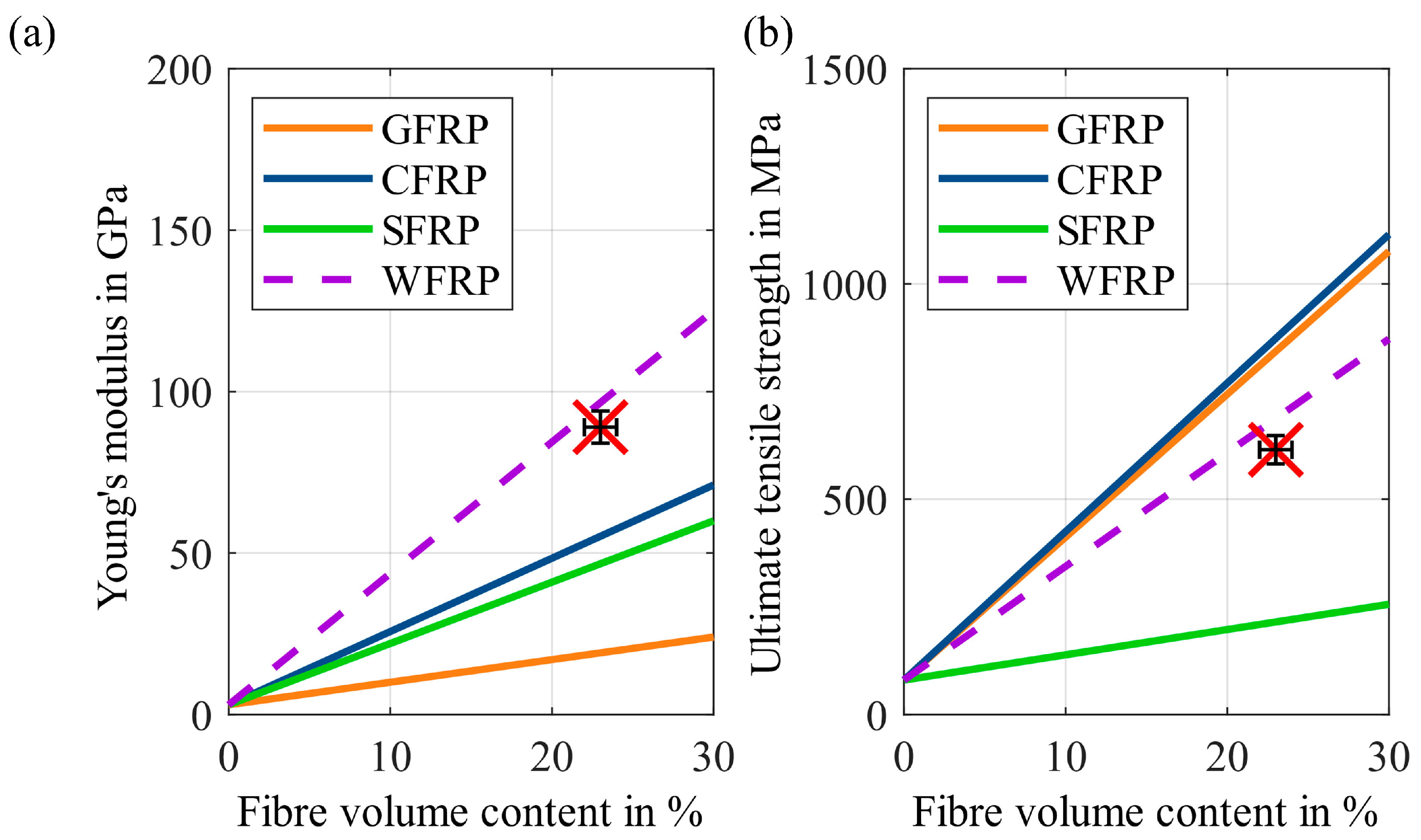
2.4. Modelling Using the Rule of Mixture
3. Results and Discussion
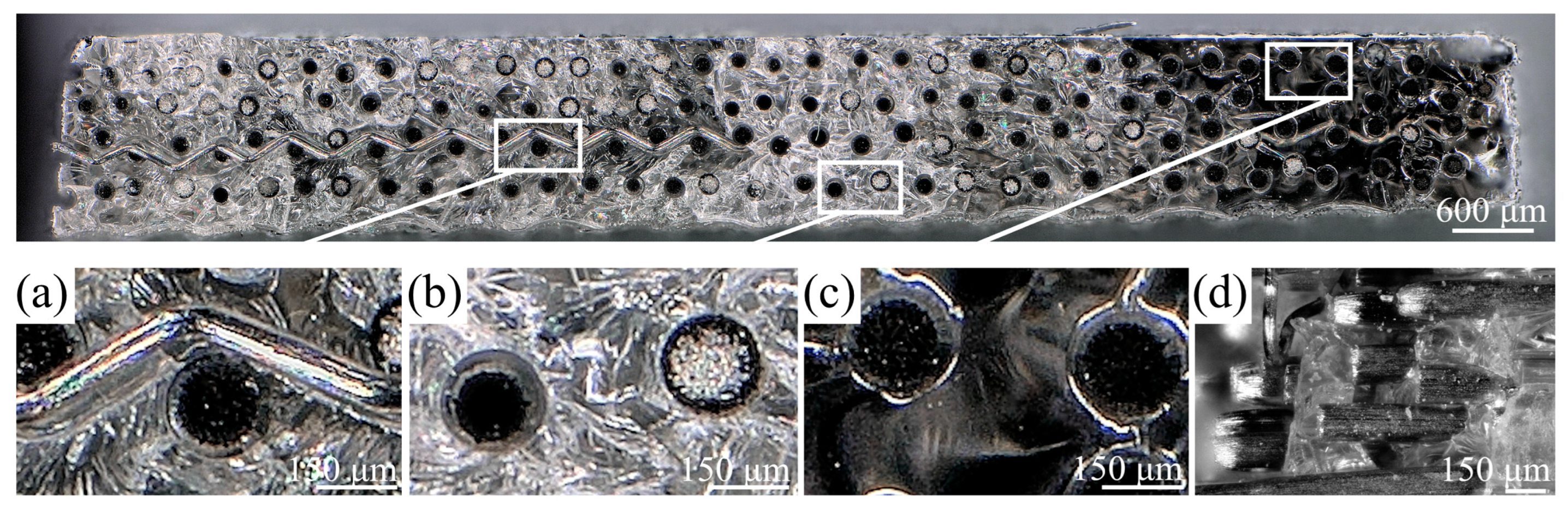
3.1. Production of Composite Specimens
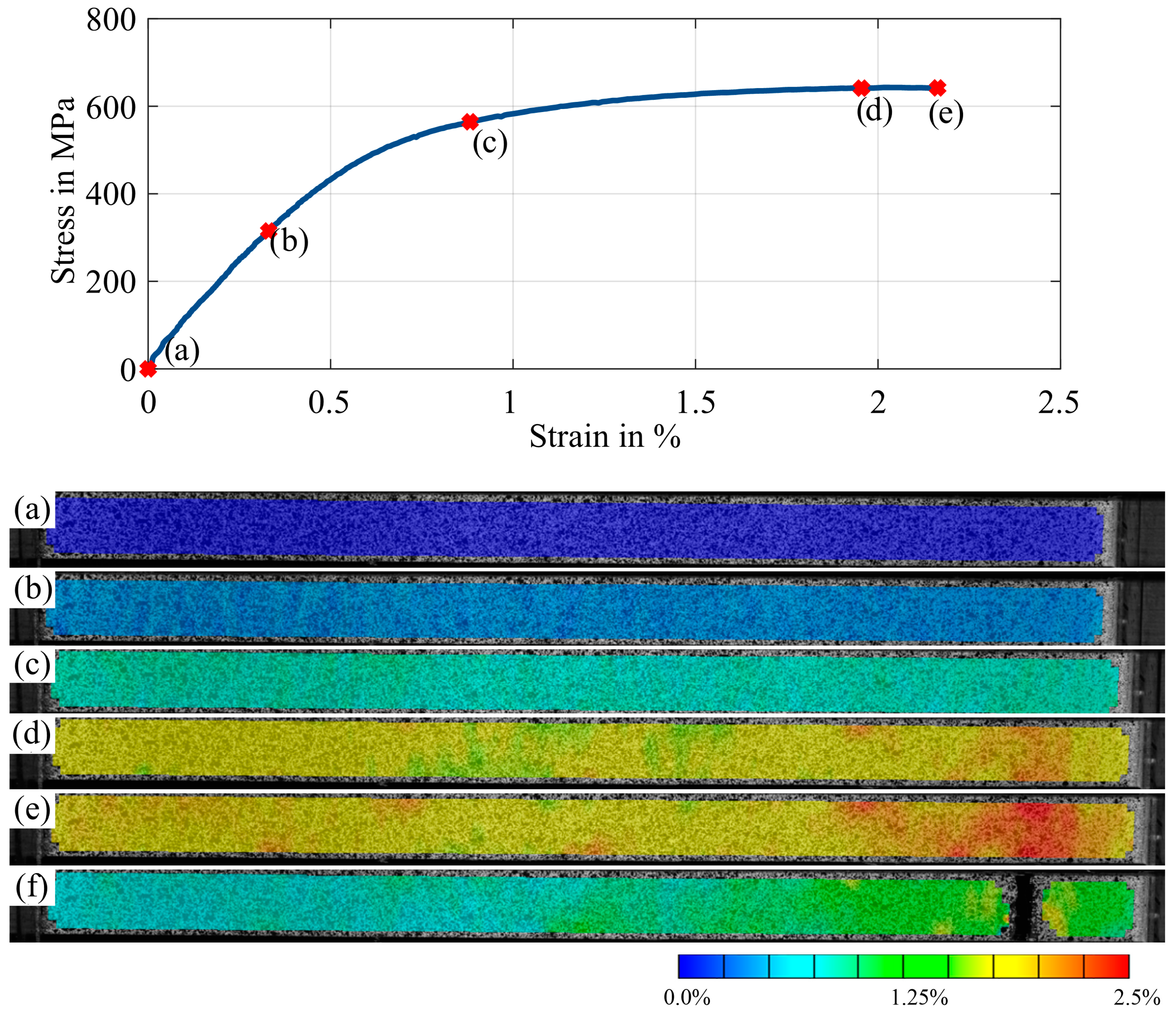
3.2. Tensile Properties
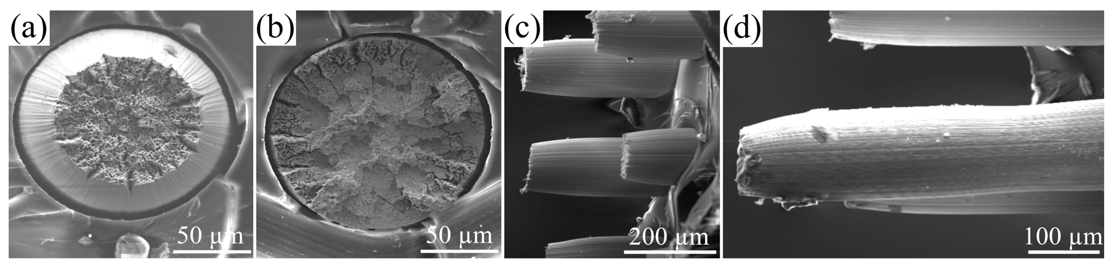
3.3. Fracture Analysis
3.4. Potential of Tungsten Fibres in Fibre-Reinforced Polymers
4. Summary and Conclusions
Author Contributions
Funding
Data Availability Statement
Acknowledgments
Conflicts of Interest
Appendix A
References
- Cherif, C. (Ed.) Textile Materials for Lightweight Constructions: Technologies-Methods-Materials-Properties; Springer: Berlin/Heidelberg, Germany, 2016; ISBN 9783662463406. [Google Scholar]
- Witten, E.; Sauer, M.; Kühnen, M. Composites-Marktbericht 2017: Marktentwicklungen, Trends, Ausblicke und Herausforderungen. Available online: https://www.avk-tv.de/files/20171026_avkccev__marktbericht_2017.pdf (accessed on 27 August 2018).
- Swolfs, Y.; Gorbatikh, L.; Verpoest, I. Fibre hybridisation in polymer composites: A review. Compos. Part A Appl. Sci. Manuf. 2014, 67, 181–200. [Google Scholar] [CrossRef]
- Swolfs, Y.; Verpoest, I.; Gorbatikh, L. Recent advances in fibre-hybrid composites: Materials selection, opportunities and applications. Int. Mater. Rev. 2019, 64, 181–215. [Google Scholar] [CrossRef]
- Breuer, U.P.; Schmeer, S.; Eberth, U. Carbon and Metal Fibre Reinforced Airframe Structures—A New Approach to Composite Multifunctionality. 2013. Available online: https://www.dglr.de/publikationen/2013/301393.pdf (accessed on 23 March 2025).
- Callens, M.G.; Gorbatikh, L.; Verpoest, I. Ductile steel fibre composites with brittle and ductile matrices. Compos. Part A Appl. Sci. Manuf. 2014, 61, 235–244. [Google Scholar] [CrossRef]
- Allaer, K.; de Baere, I.; Lava, P.; van Paepegem, W.; Degrieck, J. On the in-plane mechanical properties of stainless steel fibre reinforced ductile composites. Compos. Sci. Technol. 2014, 100, 34–43. [Google Scholar] [CrossRef]
- Callens, M.G.; de Cuyper, P.; Gorbatikh, L.; Verpoest, I. Effect of fibre architecture on the tensile and impact behaviour of ductile stainless steel fibre polypropylene composites. Compos. Struct. 2015, 119, 528–533. [Google Scholar] [CrossRef]
- Callens, M.G.; Gorbatikh, L.; Bertels, E.; Goderis, B.; Smet, M.; Verpoest, I. Tensile behaviour of stainless steel fibre/epoxy composites with modified adhesion. Compos. Part A Appl. Sci. Manuf. 2015, 69, 208–218. [Google Scholar] [CrossRef]
- Callens, M.G.; de Cuyper, P.; Gorbatikh, L.; Verpoest, I. Ductile steel fibre/polypropylene composites: Influence of fibre architecture on the tensile behaviour. In IV ECCOMAS Thematic Conference on the Mechanical Response of Composites, IV ECCOMAS Thematic Conference on the Mechanical Response of Composites, Azores, Portugal, 25–27 September 2013; Suleman, A., Camanho, P., Eds.; ECCOMAS (European Community on Computational Methods in Applied Sciences): Paris, France, 2013. [Google Scholar]
- Zhao, P.; Riesch, J.; Höschen, T.; Almanstötter, J.; Balden, M.; Coenen, J.W.; Himml, R.; Pantleon, W.; von Toussaint, U.; Neu, R. Microstructure, mechanical behaviour and fracture of pure tungsten wire after different heat treatments. Int. J. Refract. Met. Hard Mater. 2017, 68, 29–40. [Google Scholar] [CrossRef]
- Riesch, J.; Han, Y.; Almanstötter, J.; Coenen, J.W.; Höschen, T.; Jasper, B.; Zhao, P.; Linsmeier, C.; Neu, R. Development of tungsten fibre-reinforced tungsten composites towards their use in DEMO—Potassium doped tungsten wire. Phys. Scr. 2016, T167, 14006. [Google Scholar] [CrossRef]
- Riesch, J.; Feichtmayer, A.; Fuhr, M.; Almanstötter, J.; Coenen, J.W.; Gietl, H.; Höschen, T.; Linsmeier, C.; Neu, R. Tensile behaviour of drawn tungsten wire used in tungsten fibre-reinforced tungsten composites. Phys. Scr. 2017, T170, 14032. [Google Scholar] [CrossRef]
- Schade, P. 100years of doped tungsten wire. Int. J. Refract. Met. Hard Mater. 2010, 28, 648–660. [Google Scholar] [CrossRef]
- Briant, C.L.; Bewlay, B.P. The Coolidge Process for Making Tungsten Ductile: The Foundation of Incandescent Lighting. MRS Bull. 1995, 20, 67–73. [Google Scholar] [CrossRef]
- MCDanels, D.L.; Jech, R.W.; Weeton, J.W. Stress-Strain Behaviour of Tungsten-Fiber-Reinforced Copper Composites; NASA Technical Note; National Aeronautics and Space Administration: Washington, DC, USA, 1963.
- Petrasek, D.W.; Signorelli, R.A.; Weeton, J.W. Refractory-Metal-Fiber—Nickel-Base-Alloy Composites for Use at High Temperatures; NASA Technical Note; National Aeronautics and Space Administration: Washington, DC, USA, 1968.
- Riesch, J.; Aumann, M.; Coenen, J.W.; Gietl, H.; Holzner, G.; Höschen, T.; Huber, P.; Li, M.; Linsmeier, C.; Neu, R. Chemically deposited tungsten fibre-reinforced tungsten—The way to a mock-up for divertor applications. Nucl. Mater. Energy 2016, 9, 75–83. [Google Scholar] [CrossRef]
- Riesch, J.; von Müller, A.; Mao, Y.; Coenen, J.W.; Böswirth, B.; Elgeti, S.; Fuhr, M.; Greuner, H.; Höschen, T.; Hunger, K.; et al. Progress in the development of industrial scale tungsten fibre-reinforced composite materials. Nucl. Mater. Energy 2024, 38, 101591. [Google Scholar] [CrossRef]
- Flemming, M.; Ziegmann, G.; Roth, S. Faserverbundbauweisen; Springer: Berlin/Heidelberg, Germany, 1995; ISBN 978-3-642-63352-2. [Google Scholar]
- Parker, B.M. Boron fibre and boron reinforced composites. Article 5 in the series—Composite materials and the designer. Composites 1974, 5, 7–15. [Google Scholar] [CrossRef]
- Kawazoe, S.; Kagawa, Y. Determination of initial interface debonding in tungsten fibre reinforced epoxy composite using photon emission and electric current fluctuation. Mater. Sci. Technol. 2001, 17, 338–342. [Google Scholar] [CrossRef]
- Kagawa, Y.; Hsueh, C.-H. Model experiment on a protrusion method for measurement of interface shear sliding stress in fiber-reinforced composite. Mater. Sci. Eng. A 1999, 271, 70–78. [Google Scholar] [CrossRef]
- Guo, S.; Honda, K.; Kagawa, Y. Interface debonding from bottom face and frictional transition during pushout testing of a tungsten fiber-epoxy matrix composite. Compos. Sci. Technol. 2005, 65, 1808–1814. [Google Scholar] [CrossRef]
- Toray Carbon Fibers America Inc. T300 Standard Modulus Carbon Fiber. Available online: https://www.toraycma.com/page.php?id=661 (accessed on 11 January 2019).
- Saint-Gobain Vetrotex Deutschland GmbH. E, R and D Glass Properties: Technical Data Sheet. Available online: http://glassproperties.com/glasses/E_R_and_D_glass_properties.pdf (accessed on 11 January 2019).
- Mosleh, Y.; Clemens, D.; Gorbatikh, L.; Verpoest, I.; van Vuure, A.W. Penetration impact resistance of novel tough steel fibre-reinforced polymer composites. J. Reinf. Plast. Compos. 2015, 34, 624–635. [Google Scholar] [CrossRef]
- Produktdatenblatt Biresin CR80: Compositharz-System. 2017. Available online: https://deu.sika.com/dam/dms/deaddconst01/a/sikabiresin-cr80.pdf (accessed on 23 March 2025).
- Smid, I.; Akiba, M.; Vieider, G.; Plöchl, L. Development of tungsten armor and bonding to copper for plasma-interactive components. J. Nucl. Mater. 1998, 258–263, 160–172. [Google Scholar] [CrossRef]
- Fischer, U.; Gomeringer, R.; Kilgus, R.; Näher, F.; Oesterle, S.; Paetzold, H.; Stephan, A.; Winkow, R. Tabellenbuch Metall, 45. Aufl., 3. Dr; Verl. Europa-Lehrmittel Nourney Vollmer: Haan-Gruiten, Germany, 2011; ISBN 9783808517253. [Google Scholar]
- Lassner, E.; Schubert, W.-D. Tungsten: Properties, Chemistry, Technology of the Element, Alloys, and Chemical Compounds; Kluwer Academic: New York, NY, USA, 1999; ISBN 9780306450532. [Google Scholar]
- Garret, K.W.; Rosenberg, H.M. The therma conductivity od epoxy-resin/powder composite materials. J. Phys. D Appl. Phys. 1974, 7, 1247–1258. [Google Scholar] [CrossRef]
- Hancox, N.L.; Mayer, R.M. Design Data for Reinforced Plastics: A Guide for Engineers and Designers; Springer-Science + Business Media: Dordrecht, The Netherlands, 1994; ISBN 978-94-011-0707-5. [Google Scholar]
- Gietl, H.; Müller, A.v.; Coenen, J.W.; Decius, M.; Ewert, D.; Höschen, T.; Huber, P.; Milwich, M.; Riesch, J.; Neu, R. Textile preforms for tungsten fibre-reinforced composites. J. Compos. Mater. 2018, 1, 002199831877114. [Google Scholar] [CrossRef]
- Schmidt, R.G.; Bell, J.P. Epoxy adhesion to metals. In Epoxy Resins and Composites II; Dušek, K., Ed.; Springer: Berlin/Heidelberg, Germany, 1986; ISBN 9783540396574. [Google Scholar]
- Kanerva, M.; Koerselman, J.R.; Revitzer, H.; Johansson, L.-S.; Sarlin, E.; Rautiainen, A.; Brander, T.; Saarela, O. Structural Assessment of Tungsten-Epoxy Bonding in Spacecraft Composite Enclosures with Enhanced Radiation Protection. In Proceedings of the 13th European Conference on Spacecraft Structures, Materials & Environmental Testing, Braunschweig, Germany, 1–4 April 2014; Volume 727, p. 123. [Google Scholar]
- Kanerva, M.; Johansson, L.-S.; Campbell, J.M.; Revitzer, H.; Sarlin, E.; Brander, T.; Saarela, O. Hydrofluoric–nitric–sulphuric-acid surface treatment of tungsten for carbon fibre-reinforced composite hybrids in space applications. Appl. Surf. Sci. 2015, 328, 418–427. [Google Scholar] [CrossRef]
- Deutsches Institut für Normung. Kunststoffe: Bestimmung der Zugeigenschaften—Teil 5: Prüfbedingungen für unidirektional faserverstärkte Kunststoffe, 2010-10; Beuth Verlag (527-5): Berlin, Germany, 2022; Available online: https://www.dinmedia.de/de/norm/din-en-iso-527-5/349263704 (accessed on 23 March 2025).
- Alger, M. Polymer Science Dictionary; Springer: Dordrecht, The Netherlands, 2017; ISBN 978-94-024-0891-1. [Google Scholar]
- Edwards, K.L. An overview of the technology of fibre-reinforced plastics for design purposes. Mater. Des. 1998, 19, 1–10. [Google Scholar] [CrossRef]
- Laval, C. Composites design in the real world. Reinf. Plast. 2003, 47, 50–53. [Google Scholar] [CrossRef]
- Lomov, S.V.; Bogdanovich, A.E.; Karahan, M.; Mungalov, D.; Verpoest, I. Mechanical behaviour of non-crimp 3D woven caron/epoxy composite under in-plane tensile loading. In Proceedings of the International Conference on composite materials, Jeju Island, Republic of Korea, 21–26 August 2011. [Google Scholar]
- Pardo, S.; Baptiste, D.; Decobert, F.; Fitoussi, J.; Joannic, R. Tensile dynamic behaviour of a quasi-unidirectonal E-glass/polyester composite. Compos. Sci. Technol. 2002, 62, 579–584. [Google Scholar] [CrossRef]
- Greenhalgh, E.S. Failure Analysis and Fractography of Polymer Composites; Woodhead Pub: Cambridge, UK, 2009; ISBN 9781845692179. [Google Scholar]
- Riesch, J.; Almanstötter, J.; Coenen, J.W.; Fuhr, M.; Gietl, H.; Han, Y.; Höschen, T.; Linsmeier, C.; Travitzky, N.; Zhao, P.; et al. Properties of drawn W wire used as high performance fibre in tungsten fibre-reinforced tungsten composite. IOP Conf. Ser. Mater. Sci. Eng. 2016, 139, 12043. [Google Scholar] [CrossRef]
- Maleque, M.A.; Salit, M.S. Materials Selection and Design; Springer: Singapore, 2013; ISBN 978-981-4560-37-5. [Google Scholar]
- Neu, R.; Riesch, J.; Müller, A.; Balden, M.; Coenen, J.W.; Gietl, H.; Höschen, T.; Li, M.; Wurster, S.; You, J.-H. Tungsten fibre-reinforced composites for advanced plasma facing components. Nucl. Mater. Energy 2017, 12, 1308–1313. [Google Scholar] [CrossRef]
- Gietl, H.; Riesch, J.; Coenen, J.W.; Höschen, T.; Linsmeier, C.; Neu, R. Tensile deformation behavior of tungsten fibre-reinforced tungsten composite specimens in as-fabricated state. Fusion Eng. Des. 2017, 124, 396–400. [Google Scholar] [CrossRef]
- The MathWorks, I. std: Standard Deviation. Available online: https://de.mathworks.com/help/matlab/ref/std.html (accessed on 23 September 2019).

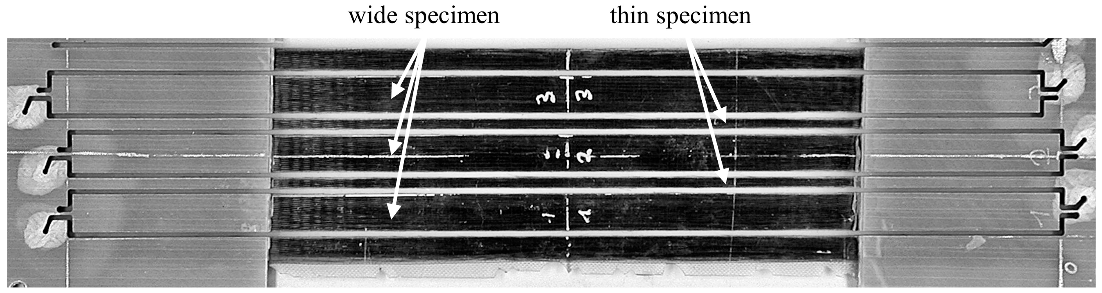

| Specimen Type | Wide | Thin | Epoxy |
|---|---|---|---|
| Valid specimens | 10 | 5 | 5 |
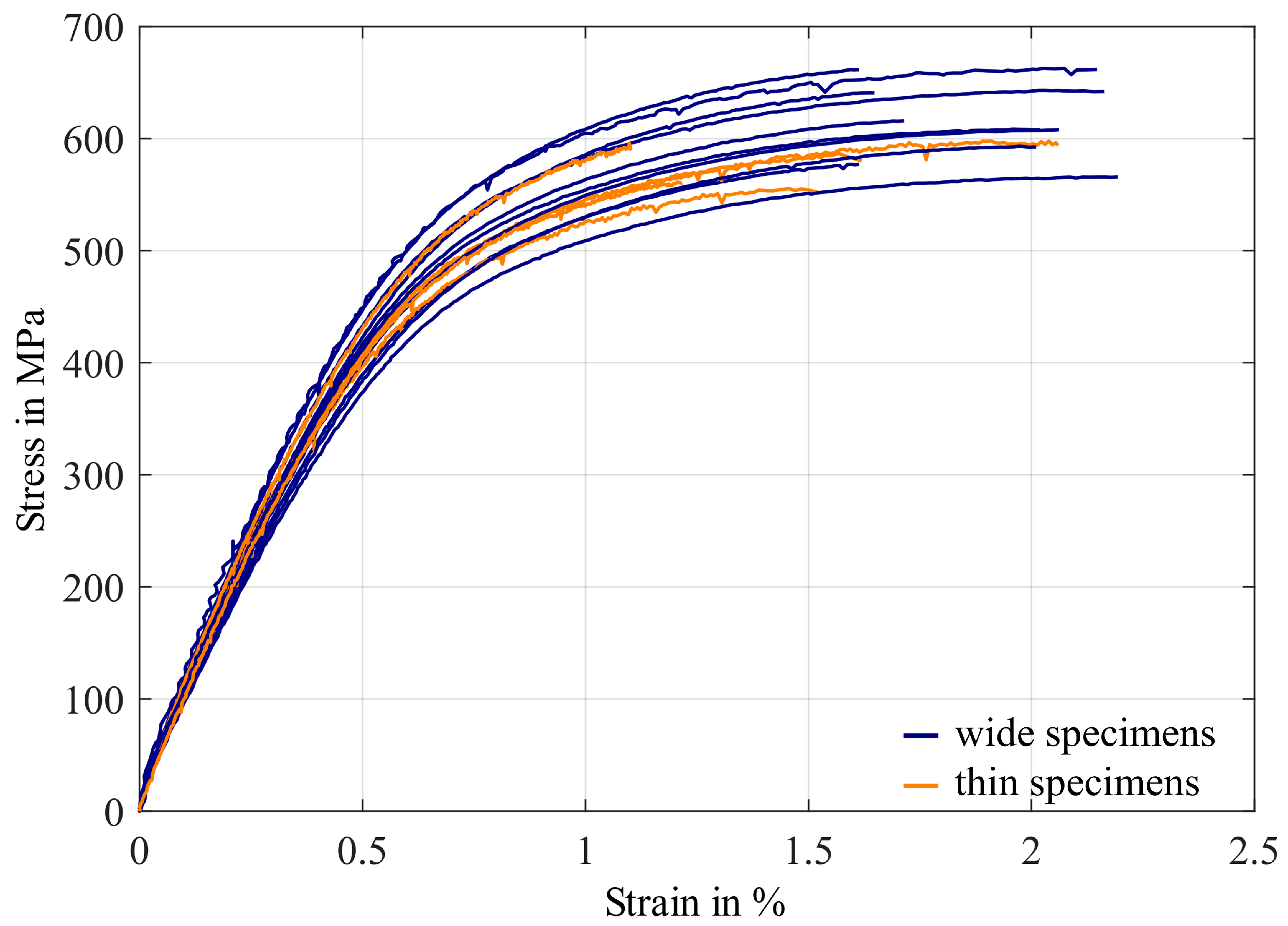
| Young’s modulus in GPa | 89 ± 5 | 91 ± 2 | 3.1 ± 0.1 |
| Ultimate tensile strength in MPa | 615 ± 33 | 576 ± 18 | 66 ± 2 |
| Failure strain in % | 1.9 ± 0.2 | 1.5 ± 0.4 | 4.4 ± 1.1 |
Disclaimer/Publisher’s Note: The statements, opinions and data contained in all publications are solely those of the individual author(s) and contributor(s) and not of MDPI and/or the editor(s). MDPI and/or the editor(s) disclaim responsibility for any injury to people or property resulting from any ideas, methods, instructions or products referred to in the content. |
© 2025 by the authors. Licensee MDPI, Basel, Switzerland. This article is an open access article distributed under the terms and conditions of the Creative Commons Attribution (CC BY) license (https://creativecommons.org/licenses/by/4.0/).
Share and Cite
Dickes, D.; Maidl, S.; Riesch, J.; Neu, R.; Drechsler, K. Manufacturing and Characterisation of a Tungsten Fibre-Reinforced Polymer Composite. J. Compos. Sci. 2025, 9, 161. https://doi.org/10.3390/jcs9040161
Dickes D, Maidl S, Riesch J, Neu R, Drechsler K. Manufacturing and Characterisation of a Tungsten Fibre-Reinforced Polymer Composite. Journal of Composites Science. 2025; 9(4):161. https://doi.org/10.3390/jcs9040161
Chicago/Turabian StyleDickes, Daniel, Stephan Maidl, Johann Riesch, Rudolf Neu, and Klaus Drechsler. 2025. "Manufacturing and Characterisation of a Tungsten Fibre-Reinforced Polymer Composite" Journal of Composites Science 9, no. 4: 161. https://doi.org/10.3390/jcs9040161
APA StyleDickes, D., Maidl, S., Riesch, J., Neu, R., & Drechsler, K. (2025). Manufacturing and Characterisation of a Tungsten Fibre-Reinforced Polymer Composite. Journal of Composites Science, 9(4), 161. https://doi.org/10.3390/jcs9040161