Article

Study of Systems of Active Vibration Protection of Navigation Instrument Equipment

1
Łukasiewicz Research Network—Industrial Research Institute for Automation and Measurements PIAP, 02-486 Warsaw, Poland
2
National Technical University of Ukraine “Igor Sikorsky Kyiv Polytechnic Institute”, 03056 Kyiv, Ukraine
3
The Ukrainian Scientific and Research Institute of Special Equipment and Forensic of the Security Service of Ukraine, 03113 Kyiv, Ukraine
*
Author to whom correspondence should be addressed.
Appl. Syst. Innov. 2024, 7(5), 95; https://doi.org/10.3390/asi7050095
Submission received: 1 August 2024 / Revised: 27 September 2024 / Accepted: 29 September 2024 / Published: 30 September 2024

Abstract

:
Assessment of the influence of vibration isolator parameters on the distribution of the system’s natural frequencies is a significant task in the design of vibration isolation systems. The root method was used to determine the natural frequencies of the controlled vibration isolator. For a certain feedback structure of a controlled electrodynamic type vibration isolator, the need for a consistent selection of parameters has been justified. A mathematical solution has been proposed for the approximate determination of the roots of the characteristic equation of the controlled vibration isolator, which enables the analytical assessment of the influence of the vibration isolator parameters on the distribution of its natural frequencies. The research has been conducted in relative parameters, which makes it possible to generalize the results. The specificity of the inertial dynamic vibration isolator, which in some cases is associated with the implementation of anti-resonance conditions, can lead to the fact that resonant frequencies can occur on both sides of the tuning frequency of the vibration isolator. The use of an elastic suspension on flat springs to protect navigation equipment from vibration allows reduction in the intensity of translational vibration, while not changing the orientation of the device relative to the Earth. The implementation of an elastic suspension according to the scheme of the inverted pendulum allows an increase in the effectiveness of vibration isolation, under the conditions of a controlled change of the vibration isolator parameters and due to the use of feedback. The results of this research can be used in precision systems, such as vibration isolators, laser processing equipment, ultraprecision measurements or medical devices.

1. Introduction

The safety of the movement of air and sea vessels significantly depends on accuracy in determining their navigational parameters. The initial orientation of the navigation systems of ships is carried out with the help of ground-based precision instrument equipment, which works in the condition of an external wave of vibration disturbance. Vibration disturbances arise as a result of the operation of power equipment, refueling equipment, the operation of other mechanisms and machines. This has the effect of reducing the accuracy of determining navigation parameters and incorrectly entering initial information into the navigation systems of air and sea vessels. One of the methods of increasing the accuracy of ground-based navigation systems is their protection against vibration. The frequency range of such vibrations and part of the natural frequencies of ground-based navigation devices practically coincide and are equal to one Hz. The application of equipment vibration protection for passive vibration isolation systems is ineffective in such working conditions. Therefore, the development of a system of active protection against vibration for ground-based instrument navigation equipment is a necessary condition for increasing the accuracy of such systems and, as a result, increasing the safety of air and sea vessels.
Increasing the accuracy of determining the navigational parameters of the movement of air and sea vessels will lead to fuel savings for aircraft due to the reduction in the deviation of the real trajectory of the vessels from the calculated one, as well as to the reduction in unforeseen expenses of ship owners.
Most modern navigation devices use the compensation method of azimuth measurement [1], in which the output signal of the device is the voltage on the windings of the feedback torque sensor (TS).
The scheme shown in Figure 1 is used in the tasks of vibration protection of devices, apparatus, and other precise mechanisms, which are sensitive to vibrations and installed on oscillating bases or on moving objects. The vibration isolation device is the most important part of the anti-vibration system and its purpose is to create such a mode of movement, which is initiated by given excitations, that the purpose of protecting the object is realized. In many cases, this is achievable when using a vibration isolation device.
Vibration isolators are devices that are used to protect machines and equipment from the effects of vibration and shock loads. A controlled vibration isolator is an integral part of many precision systems, such as laser processing equipment, medical devices, precision sensors, ultraprecision machining and ultraprecise measurements [2,3,4,5,6]. In order to ensure the maximum accuracy and stability of the operation of such systems, it is necessary to know the natural frequencies of the controlled vibration isolator [7,8,9]. The root method can be used to determine the natural frequencies of the controlled vibration isolator. This method is based on finding the roots of the characteristic equation of the system. The characteristic equation is an equation that determines the dynamic behavior of the system under the influence of external factors. First, it is necessary to determine the stiffness matrix and the mass matrix of the system. Next, the root method consists in finding the eigenvalues (frequencies) and eigenvectors of the stiffness matrix. Eigenvectors are vectors that determine the form of the system oscillation at the corresponding eigenfrequencies.
The root method is one of the ways to determine the natural frequencies of a controlled vibration isolator. This method consists in measuring the amplitude of system oscillations at different frequencies of the external disturbance and constructing a graph of the amplitude dependence on the frequency. The natural system frequency is defined as the frequency at which the amplitude of oscillations reaches its maximum value.
The application of the root method requires the use of special devices, such as a vibrometer, which allows the measurement of the system oscillations’ amplitude, and a signal generator to create an external disturbance [10]. When using the root method, it is also necessary to take into account the influence of factors that can affect the accuracy of measurements, for example, vibrations from other sources, electromagnetic interference, etc. [11,12,13].
In general, determining the natural frequencies of the controlled vibration isolator by the root method is a significant stage in the development and operation of precision systems [14,15,16,17]. This method allows for maximum accuracy and stability of system operation and helps to avoid possible errors and unforeseen situations when working with such equipment.
Internal resonances inside vibration isolators increase force transmission and, as a result, radiated noise from supporting structures [18]. This article proposes a new concept, i.e., a uniaxial vibration isolator, which includes transmission absorbers to suppress internal resonance.
For vibration isolators with a high degree of damping, the bandwidth is already quite low at higher frequencies. However, internal resonances can have a significant effect on the sound power emitted by the supporting structure [19]. The article shows that this effect increases to 22 dB in the frequency range of 200–3000 Hz compared to an ideal vibration isolator. The system consisted of a primary mass with three degrees of freedom (rebound, pitch, and roll), supported by three vibration isolators on a rectangular plate. To reduce the effect of internal resonance, Du et al. [20] developed a composite vibration isolator that included two active dynamic vibration absorbers (DVAs) attached to intermediate masses. The power transfer in the two frequency bands was minimized by optimizing the passive properties of the DVA. Experiments demonstrated a decrease in power transmission and acoustic power of sound up to 20 dB and 4.3 dB, respectively. In [21], a similar system with vibration isolators consisting of periodic structures was studied to suppress the effect of internal resonance on the transmitted force and radiated noise. The importance of resonances in active vibration isolation systems was recognized in [22], which demonstrated velocity feedback and the failure to suppress this. In addition, internal resonances have been shown to cause stability problems.
The behavior of an active isolation system with a biased connection is investigated in [23] subject to the limitations of the output signal of the actuator. Distributed parameter models are developed to analyze system response and generate a transfer matrix for designing an integrated passive–active isolation system.
Reducing the transmission of vibration from the machine to its supporting structure has been the subject of considerable research [24,25,26,27], including research into active, semi-active and passive control [28].
Practical control systems are usually implemented using digital filters and control algorithms formulated in the time domain; the perturbations being monitored are in many cases periodic. The direct control algorithm in the frequency domain was first applied to the problem of four active isolators between a vertically vibrating solid body and a flexible plate clamped at the edge [29,30]. The effectiveness of the insulation and the predicted value of the control forces were investigated by the finite element method. The analysis for many excitation forces and different types of support structures was carried out using modal analysis [31,32,33].
In article [15], the authors studied the influence of the elastic element geometry on the natural frequency of the vibration isolator. The results showed that changing the shape and size of the elastic element can significantly affect the natural frequency of the vibration isolator.
In [16], the authors investigated the influence of geometrical parameters of vibration isolators on their dynamic characteristics, demonstrating that the geometric parameters of these vibration isolators, such as wire diameter, length, number of wires, and their relative placement, can affect the dynamic characteristics.
In article [17], the authors investigated the influence of the shape of the elastic element on the dynamic characteristics of the vibration isolator. The results showed that changing the shape of the elastic element can significantly affect the natural frequency and amplitude of the isolator vibration.
Studies of the geometric parameters’ influence on the dynamic characteristics of cylindrical wire vibration isolators have been carried out in a number of scientific works [13,34]. For example, in article [34], the authors investigated the influence of such parameters as the number of wires, their diameter, and the distance between the wires, on the natural frequency and gassing of the vibrations of these isolators. Studies have shown that an increase in the number of wires and a decrease in their diameter leads to a decrease in the natural frequency of the cylindrical vibration isolator and an increase in its gassing. The results showed that the diameter and height of the metal springs, which are part of the vibration isolator, have a significant effect on the natural frequency and amplitude of oscillation.
Zou investigated the influence of the shape of the elastic element on the dynamic characteristics of the vibration isolator [35]. The results showed that the dynamic stiffness and loss factor calculated by the two different test methodologies were significantly different, indicating that the inertial force effect of the dynamic test equipment should be considered when applying the elliptical method. It was found that the change in the shape of the elastic element can significantly affect the natural frequency and oscillation amplitude of the vibration isolator.
Xian He studied the optimization of vibration isolator parameters using genetic algorithms [36]. The results showed that optimizing the parameters of the vibration isolator can increase its efficiency.
Conducted research in this area has allowed development of new designs for passive vibration-isolating devices with quasi-zero stiffness, in which either specially designed elastic elements are used, or non-standard types of loading of standard elastic elements are implemented [37]. Such designs are not widely used in technology, since most of them are made in the form of passive safety devices with single activation. Their main drawback is the additional setting of the device, which worked during resonant torsional oscillations. In addition, such devices, as a rule, are not designed for reversible drives.
To solve the resonance problem, a device is needed that determines the “jump” point, both for harmonic resonance and in the region of higher-order instability. In structures with a cubic-nonlinear stiffness characteristic, even in the presence of a region of quasi-zero stiffness, it is very difficult to obtain such a characteristic [6,7,12]. There is a high probability that such a characteristic exists and is directly related to the exponent of the function describing the nonlinear stiffness characteristic [38,39]. However, without the introduction of active links to adjust the stiffness, it is impossible to obtain such a characteristic [40]. The solution to this problem determines a qualitatively new approach to the organization of the structure of the device, i.e., the vibration isolator. In addition to the direct connection with the torque transmission elements, the vibration isolator must also have feedback that determines its self-adjustment according to some selected criteria.
Therefore, to determine the natural frequencies of the controlled vibration isolator, the use of the root method is one of the most accurate and reliable [41,42]. It is based on measuring the vibrational response of the system by means of impulse disturbances with a root frequency.
In the literature, there are many scientific studies and articles describing the principle of action and application of the root method for determining the natural frequencies of a controlled vibration isolator [43,44,45]. Many authors provide practical recommendations for using this method, including the vibration response measurement, the obtained data processing, and the analysis of the results [46].
It is also noted in the literature [47] that the accuracy of determining the natural frequencies of the controlled vibration isolator depends on a number of factors, such as the accuracy of the measuring equipment, the quality of impulse disturbances, etc. Some studies are devoted to the study of the influence of various factors on the accuracy of determining the natural frequencies of a controlled vibration isolator using the root method.
Prospective methods of improving the operational characteristics of equipment from the point of view of reducing the degree of influence of external disturbing factors, such as kinematic, vibration, and acoustic factors, are passive, active and compensatory methods [48,49]. Passive methods include methods of design and technological improvements that make it possible to reduce the impact of sound and vibration without additional energy sources and do not require information about the nature of the excitation effect [49]. Active methods include those that are based on the use of external information and additional energy sources and enable compensation for mechanical disturbing factors [50]. Compensatory methods are based on the ideology of compensation of manifestations of excitement and do not require the use of energy sources and information about the nature of external influence [51].
Methods of damping vibration, which propagates through supporting structures, are widely used [52,53,54]. One of the means of broad-band vibration isolation in the medium and high-frequency areas of the sound range is to cover the elements and housings of devices with a vibration-absorbing coating, but this method leads to an increase in the total mass of the object, and the significant non-linearity of the frequency characteristic of vibration isolation coatings forces us to look for new methods and means of combating vibration.
The use of active methods involves the creation by special generators of an additional exciting field of the same physical structure with a given amplitude-phase characteristic. [55]. Recently, such methods have been widely used in electronic equipment protection systems. Like active sound absorption systems, active vibration protection methods require the presence of a sensitive element (elements) at a certain point of the vibration field, as well as a system for amplifying and transmitting this information on the way to the emitter.
The characteristics of the energy state of the system of active acoustic and vibration isolation are determined by the energy consumption in the converting devices depending on the operating conditions. The active vibration protection system is more effective with a narrower area of space where the vibrational energy from an external source is materialized. A serious limitation of this is the impossibility of broad-band suppression of modulation oscillations. In the case of expanding the operating frequency, conditions for positive feedback arise and, as a result, the stability of the system as a whole is lost or local self-excitation is created.
A comparative analysis shows that the technical implementation of active vibration protection is more complex than acoustic, due to the occurrence of various types of vibrations in solid-state structures, i.e., bending, longitudinal, shear, etc., which leads to the need to introduce additional receivers and emitters into the vibration protection system’s sound.
The article investigates one of the main elements of measuring elements in vibration protection and vibration reproduction systems, which is elastic suspension. Suspension on flat springs is most often used, a feature of which is the practical absence of relative angular rotation and relative translational movement of suspension parts, as well as the practical absence of dry friction. When using an elastic suspension in the form of an inverted pendulum on vertically located and cantilever-fixed flat springs, it is possible to obtain a natural frequency of the suspension in the horizontal plane of about 1 Hz.
The high kinematic selectivity of such a suspension regarding the direction of the measured or reproduced vibration and the possibility of achieving relatively low natural frequencies make it promising from the point of view of use for many practical tasks. The obtained research results can be of practical importance for the vibration isolation of navigation equipment in the area of low disturbance frequencies. Research on reducing the natural frequency of elastic suspension will allow an increase in the accuracy of existing measuring elements in vibration protection systems, as well as reduction in the dimensions of such systems and improvement in the quality characteristics of instrumentation, in particular, the accuracy of navigational geophysical devices.
This research consists in the development of a system of active protection of ground-based navigation instrumentation equipment from vibration, as well as in the justification of the choice of feedback parameters. The dynamics and effectiveness are investigated of the active vibration isolator and methods developed for calculating the elastic suspension and the executive mechanism.
The purpose of the study is to improve the accuracy of navigation instrumentation installed on a limited movable base. For the set goal, it is planned to create a system of active protection against translational vibration in the horizontal plane with the estimated efficiency of vibration isolation of the instrument equipment in the frequency range of 0.8, …, 5 Hz–−10, …, −12 dB. This range is the most dangerous, from the point of view of measurement error, and the natural frequency of the pendulum gyrocompass is 1, …, 2 Hz. Vibrational external disturbances also belong to the studied frequency range.

2. Materials and Methods

Vibration isolation systems can be designed in a complex with the protected object as its integral part (for example, suspensions of railway cars and cars, ship diesel installations, etc.). Otherwise, the design of anti-vibration systems has an individual character and is carried out according to the consequences of static and dynamic calculations (the same devices and equipment, depending on the installation locations, are exposed to excitations that are completely different in form or intensity).
In a simple model of the anti-vibration system, which allows study of the spatial movement of the source and the object, both of these bodies are considered as absolutely solid. The set of vibration isolators connecting them forms an elastic suspension.
The suspension calculation consists of two parts: static, which consists in the calculation of static reactions and static deformations of vibration isolators; and dynamic, which consists in determining the natural frequencies of the elastically suspended supporting body and calculating the characteristic parameters of its movement.
A rationally designed suspension must first of all exclude the possibility of resonance oscillations in the system. Therefore, it is necessary that, with a relatively low level of damping, the frequencies of the dominant harmonics of the external disturbance exceed the largest of the natural frequencies of the system.
The quality of vibration protection also largely depends on the mutual proximity of the natural frequencies of the system. By designing suspensions based on the principle of “convergence” of natural frequencies (ideally until they completely coincide), it is possible not only to increase the degree of tuning from resonances, but also to make the supported body less sensitive (by displacement) to changes in the direction of the static load.
An essential characteristic of suspension is the degree of coherence of the system’s own oscillations. All other things being equal, suspensions with full frequency resolution are the most preferable, when a disturbance along any of the generalized coordinates causes oscillations only along this generalized coordinate.
Low-frequency vibration is one of the reasons for a significant decrease in the accuracy of precision navigation equipment. The use of passive vibration isolation systems to protect against external vibration disturbance, in this and many other cases, does not have a positive effect. Mostly, this happens due to the impossibility of ensuring relatively low natural frequencies of vibration isolation systems. The introduction into these systems of “fictitious” parameters [56,57], inertial mass, restoring force, and resistance force using the control system, allows reduction in the natural frequency of the vibration isolator, and therefore the intensity of the vibrational disturbance acting on the navigation equipment, and, as a result, an increase in its accuracy.
The use of a suspension on vertically located flat springs, built according to the scheme of an inverted pendulum, in vibration isolation systems allows, due to the achievement of a small equivalent stiffness, significant reduction in the transmission of vibration in the horizontal plane. A further reduction of the natural frequency of vibration isolation systems, and therefore a reduction of vibration transmission, is possible due to a controlled change of parameters (stiffness, mass, and resistance), but it is also limited by the need for a coordinated selection of gain coefficients value and the dynamics of individual feedback parts, determined by the stability condition. Due to the fact that, when using feedback, the order of equations that describe the dynamics of a vibration isolator increases, the calculation of its characteristics, in particular natural frequencies and the effectiveness of vibration isolation, is carried out by computational methods. The use of these methods to determine the qualitative influence picture of the parameters of individual feedback links on the vibration isolator characteristics is complicated if the number of such parameters exceeds 3, …, 4, and the order of equations exceeds 4, …, 5. In this work, a simplified method of visual assessment of the influence of feedback parameters on the effectiveness of the controlled vibration isolator has been proposed by using expressions for the approximate determination of its zeros and poles. A modal regulator is considered as a state regulator. Modal control refers to the root methods of synthesis of linear automatic control systems. With small deviations of the pendulum, the linear state regulator ensures the stability of the equilibrium position.
Dynamic vibration isolators are used to achieve a local effect: reducing the vibration activity of the object in the places of their attachment. Often, this can even be associated with the deterioration of the vibrational state of the object in other, less suitable locations.
Dynamic vibration isolators can be constructively implemented on the basis of passive elements (masses, springs, dampers) and active elements that have their own energy sources. On the basis of active elements, automatic regulation systems are used, which use electrically, hydraulically and pneumatically controlled elements.
The use of active elements expands the possibilities of dynamic vibration damping, as it allows continuous adjustment of the parameters of the dynamic vibration isolator as a function of excitations under conditions of variable vibration loads. A similar result can sometimes be achieved with the help of passive devices with non-linear characteristics. Dynamic vibration damping is used for all types of vibrations: longitudinal, bending, torsional, etc.
Such research methods as the use of linear and nonlinear differential equations, methods of automatic control theory, the theory of electromechanical systems and the theory of elasticity, numerical methods, and calculation methods using MatLAB programs, will be used in the research.
The structure of the suspension usually consists of mass-produced vibration isolators. There are vibration isolators with elastic damping characteristics, different combinations of vibration-isolating and shock-proofing properties, variations in durability and the ability to function in certain climatic conditions, as well as purely constructive features. All the listed properties are preserved to a certain extent for vibration isolators of the same type for all standard sizes.
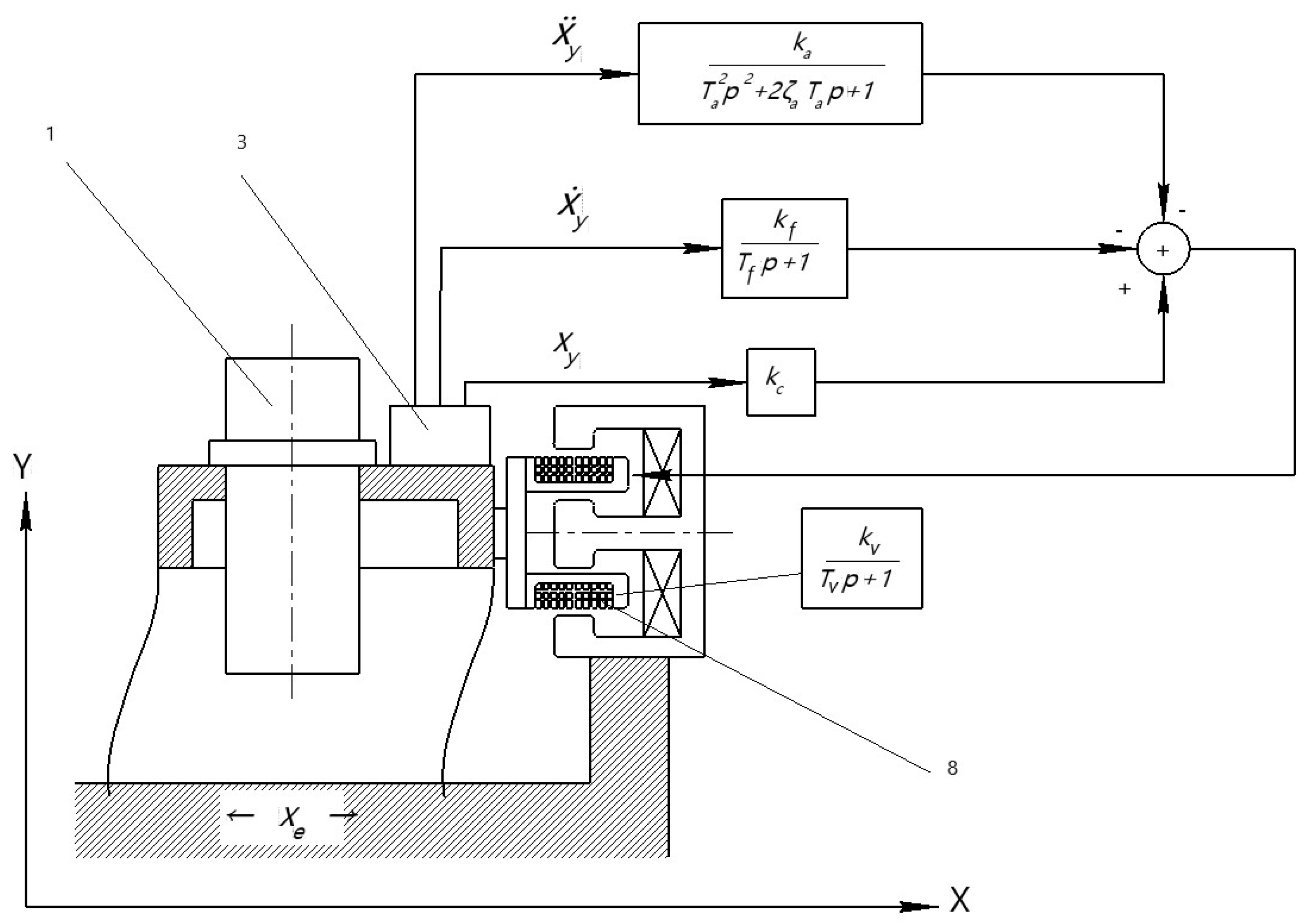
Let us consider the controlled vibration isolator (Figure 1) [56,57] with feedback, formed according to the principle of introducing “fictitious” parameters into the system (Table 1) [50]. Accordingly, the control system contains three parallel control channels with FB: a control channel for the absolute acceleration of the moving platform x ¨ , which is measured by a linear accelerometer with a time constant T a and a relative damping coefficient ζ a , a control channel for the speed of the moving platform relative to a stationary one with a low-pass filter (LPF) with the time constant T f and the relative displacement control channel with the transmission gain coefficient k c . The executive mechanism of the controlled vibration isolator is an electrodynamic vibrator with a time constant T v .
Let us use the parameters: T 0 and ζ 0 —time constant and the relative attenuation coefficient of the passive vibration isolator; χ, ξ and η—the ratio of the time constants of the accelerometer, vibrator, and LPF to the time constant of the passive vibration isolator; ζ v and ζ c —the equivalent relative attenuation coefficients introduced by the vibrator and the velocity control channel. In accordance with [58], the parameters ζ c and η are calculated depending on the value of the end-to-end transmission coefficient of the first channel— k m
ζ c = ζ ( 1 + k m ) ( 1 k c ) ζ v ζ o 1 2 η ( 1 k c ) ;   η = 1 β δ ,
where ζ —is the total relative attenuation coefficient of partial low-frequency vibrations of the controlled vibration isolator; β = ω l ω o is the ratio of the lower limit of disturbance frequencies to the natural frequency of the passive vibration isolator; δ = 1 k c 1 + k m 0 , 5 is the ratio of the natural angular frequency of the controlled vibration isolator without taking into account the dynamics of the accelerometer, electrodynamic actuator (EA), and LPF for the natural frequency of the passive vibration isolator. The first of the relations (1) makes it possible to ensure the same damping of low-frequency vibrations of the vibration isolation object for different values of km (chosen ζ ≈ 0.707), and the second to reduce the impact of controlled damping on the effectiveness of vibration isolation in the range of its operating frequencies.

3. The Mathematical Model

Figure 2 shows a diagram of the controlled vibration isolator of a gyro-theodolite (GT) built on vertically mounted flat springs, with an electrodynamic actuator (EA) and feedback proportional to the absolute acceleration of the GT body, and its displacement and speed relative to the moving base. In accordance with the adopted control algorithm, the measuring device 3 (MD) of the vibration isolator includes an accelerometer MXS3334UL and capacitive sensors measuring the relative speed and relative displacement of the moving cylindrical coil 8 of the GT. From the physical point of view, the accelerometer and relative displacement meter signals are used to increase the inertial mass of the GT and reduce the stiffness of its elastic connection with the base, and the relative velocity meter signal is used to increase the damping of low-frequency vibrations of the GT body. In order to reduce the effect of controlled damping on the effectiveness of vibration isolation in the high-frequency region, a low-pass filter (LPF) with a time constant T f is installed in the relative velocity meter circuit. Taking into account the dynamics of the accelerometer and the actuator, the system of equations of the controlled vibration isolator takes the form
m x ¨ + b x ˙ ¨ + c x U i = b   x ˙ e + c x e , v x ˙ k n x + L d i d t + R i + U a + U f = v x ˙ e k f , k a x ¨ + T a 2 U a ¨ + 2 ζ T a U a + U = 0 , k f x ¨ + T f U f + U f = k f x e ,  
where x and x e —displacement of the GT body and the movable base relative to the OXY coordinate system; U a and U f —output voltages of the accelerometer and the LPF; L and R—inductance and active resistance of the moving coil winding of the EA; υ—electromagnetic coupling coefficient; m—mass of the device; b and c—coefficients of resistance and stiffness of the elastic connection of the GT with the base; T a and ζ a —time constant and the relative attenuation coefficient of the accelerometer; k a , k f and k n —static transmission coefficients of the accelerometer, the LPF, and the relative displacement meter, respectively; T f —LPF time constant.
In order to analyze the influence of feedback parameters on the stability of the controlled vibration isolator, let us present its characteristic equation in a dimensionless form:
ξ η χ 2 ν 6 + ( 2 ς a χ ξ η + 2 ς o ξ η χ 2 + χ 2 ξ + χ 2 η ) ν 5 + ( ξ η + χ 2 + ξ η χ 2 + 2 ζ a χ ξ + 2 ζ a χ η + 4 ζ o ζ a χ ξ η + 2 ζ o χ 2 ξ + 2 ζ o χ 2 η + 2 ζ v χ 2 η ) ν 4 + ( ξ + η + 2 ζ a χ + 2 ζ a χ ξ η + 2 ζ o η ξ + 2 ζ o χ 2 + χ 2 ξ + χ 2 η + 4 ζ o ζ a χ ξ + 4 ζ o ζ a χ η + η k m + 2 ζ c χ 2 + 4 ζ v ζ a χ η + 2 ζ v χ 2 χ 2 η k c ) ν 3 + ( 1 + ξ η + χ 2 + 2 ζ o ξ + 2 ζ o η + 4 ζ o ζ a χ + 2 ζ v χ ξ + 2 ζ a χ η + k m + 4 ζ c ζ a χ + 2 ζ v η χ 2 k c + 4 ζ v ζ a χ 2 ζ a χ η k c ) ν 2 + 2 ζ o + ξ + η + 2 ζ a χ + 2 ζ c + 2 ζ v η k c 2 ζ a χ k c ν + 1 k c = 0
where T v = L R —is the time constant of the electric winding of the EA moving coil; T 0 = m c 0 , 5 and ζ 0 = b 2 × m · c 0.5 —time constant and the relative attenuation coefficient of the passive vibration isolator; χ = T a T o , ξ = T v T o and η = T f T o ,—the ratio of time constants of the accelerometer, EA, and LPF, respectively, to the time constant of the passive vibration isolator; ζ v = v 2 2 T o c R and ζ c = v k f 2 T o c R —relative attenuation coefficients due to the EA and LPF; ν—the ratio of the characteristic equation roots to the natural frequency of the passive vibration isolator ω o = 1 T 0 ; k c = v k p c R and k m = v k a m R —coefficients that physically characterize the compensation of the elastic connection of the GT with the base and the increase in its inertial mass.
In order to determine the possible values of the parameters of individual feedback elements, let us construct the stability bounds in the plane of parameters χkm. At the same time, taking into account that positive feedback can lead to a loss of stability in the controlled vibration isolator, let us accept k c ≤ 0.7. Parameters ζ c and η will be calculated depending on the value of k m , based on the condition of ensuring small resonant low-frequency oscillations of the GT (excluding the dynamics of the accelerometer, EA and LPF) and a small effect of controlled damping on the effectiveness of vibration isolation in the frequency range ω > ω l , where ω l is the lower limit of the operating range of disturbance frequencies. Let us assume that the total relative attenuation coefficient of the partial low-frequency oscillations of the controlled system is close to ζ ≈ 0.707, and the cutoff frequency of the LPF is defined as the geometric mean between the natural frequency of the controlled system, calculated without taking into account the dynamics of the accelerometer, EA, and LPF, and the lower limit of the disturbance frequencies.
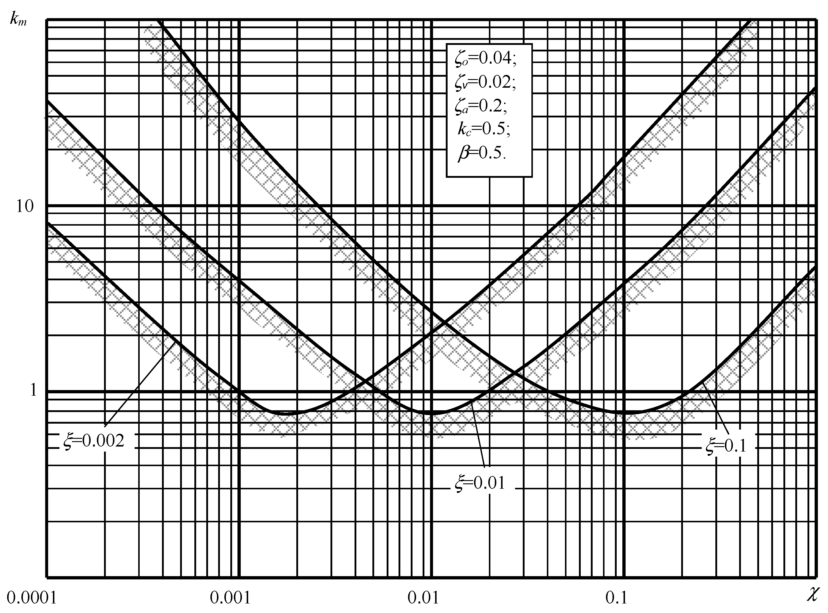
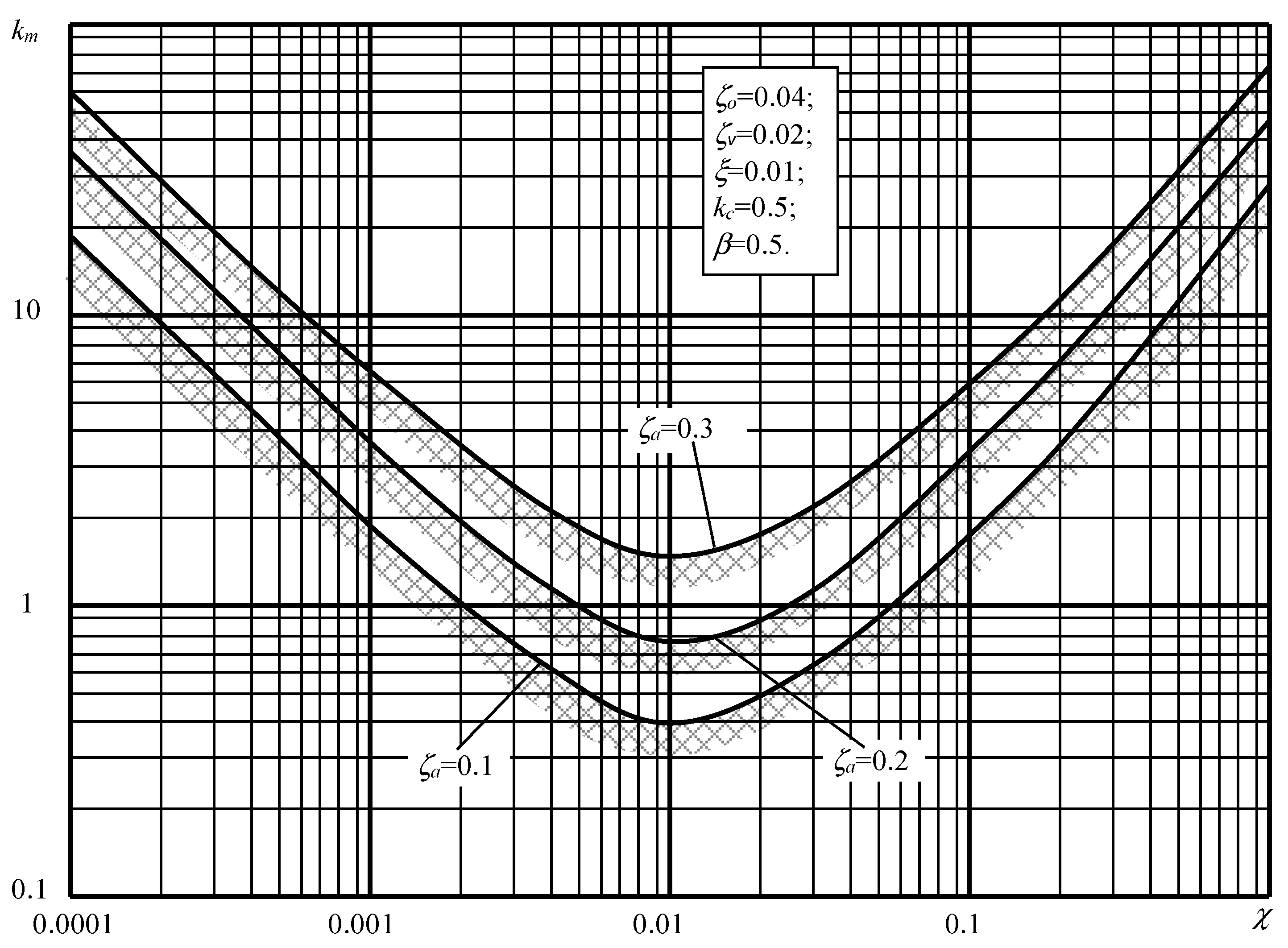
Thus, in accordance with (1), the time constant and the LPF transmission coefficient change with k m and χ, and the stability limits determine not only the actual stability of the system but also allow us to assess the nature of its low-frequency oscillations. The need for a coordinated choice of the dynamics of the EA and the accelerometer is clearly illustrated by the stability limits shown in Figure 3. Figure 4 shows similar limits, but here they characterize the effect of accelerometer damping on the stability of the controlled vibration isolator. The algorithmized Rouse’s criterion [59,60] was used to construct the stability bounds. The direct process of constructing stability limits implemented in the software includes the following steps:
  • Setting independent parameters ξ, ζa, ζo, ζv, kc and β.
  • Cycle:
    2.1.
    Setting variable parameters k m and χ .
    2.2.
    Determination by Formula (3) η and ζc.
    2.3.
    Calculation of the coefficients of the Rausch matrix for the defined k m , χ, η and ζc and checking their compliance with the sustainability criterion.
    2.4.
    Formation of a “stability” matrix for given values of variables k m and χ.

4. Building the Boundaries of Sustainability

As can be seen from the presented stability limits, the smallest possible k m value occurs at T a T v . Thus, to increase the efficiency of vibration isolation, which depends on the km value, it is necessary to increase the ratio between the accelerometer natural frequency and the frequency of the electric winding of the moving coil of the EA. It is also necessary to significantly increase the accelerometer damping.

4.1. Custom Frequencies

The area of greatest practical interest is that located in close proximity to the boundary that limits the coefficient k m from above. The choice of feedback parameters within this zone ensures that the low-frequency oscillations of the GT are close to the desired character. In this case, the roots of the characteristic Equation (2) are divided into two groups: low-frequency roots—ν1,2,3, which are caused by the dynamics of the LPF and elastic coupling, and high-frequency roots—ν4,5,6, which are caused by the dynamics of the EAD and accelerometer. Taking into account the real correlations between the parameters of the controlled vibration isolator, ζo << 1, ζv << 1, ξ << η and χ << η, to approximate the low-frequency roots, we can use the equation
η 1 + k m ν 3 + 1 + k m ν 2 + η 1 k c + 2 ζ c + ζ v + ζ o ν + 1 k c = 0 .
In order to improve the accuracy of the determination of approximate roots, let us use the procedure of squaring the roots of Equation (4) [9]. We obtain the expressions for the approximate calculation of small roots
R e ν 1 , 2 = 1 2 η 2 η 1 + k m 1 1 ν 1,2 2 = 1 k c 1 + k m 2 η 1 + k m 1 1 2 , ν 3 = 1 η 2 η 1 + k m 1 ,
where Δ = 2 ζ c + ζ o + ζ v + η 1 k c . The accuracy of determining the moduli of the low-frequency roots by expression (5) is higher the less the relative attenuation coefficient ζΣ differs from the value of 0.707.
The expressions for the approximate estimation of high-frequency roots depend on the ratio between χ and ξ. When χ >> ξ ( T a T v ), the equation for their determination takes the form
ζ χ 2 ν 6 + χ 2 ν 5 + 2 ζ a χ ν 4 + 1 + k c ν 3 = 0
Hence
ν 4 , 5 = ζ a χ + ξ 1 + k m 2 χ 2 j 1 χ 1 + k m   , ν 4 , 5 = 1 + k m χ 2 ν 6 = 1 ξ
and when ξ χ ( T v T a )
ζ χ 2 ν 6 + 2 ζ a ξ χ ν 5 + ξ ν 4 + 1 + k c ν 3 = 0
Hence
ν 4 , 5 = 1 4 ζ a χ + 1 + k m 8 ζ a 2 ξ j 1 + k m 2 ζ a χ ξ   , ν 4 , 5 = 1 + k m ξ ν 6 = 1 χ 2
Formulas (5)–(7) determine the possibility of analytical assessment of the influence of the parameters of the feedback elements on the distribution of natural frequencies of the controlled vibration isolator for the precision equipment. They can be used for the selection of parameters during the development of a controlled vibration isolator with known parameters of the external disturbance of a force’s nature, the required efficiency of vibration isolation and parameters of precision equipment.

4.2. Vibration Isolation Efficiency

The effectiveness of vibration isolation in case of kinematic disturbance is understood as the degree of realization of the goals of vibration protection by the anti-vibration device. In the case of force harmonic excitation, the goal of protection may be to reduce the amplitude of the force transmitted to a stationary object, or to reduce the amplitude of constant forced oscillations of the source. In the case of kinematic harmonic excitation, the protection consists in reducing the amplitude of absolute acceleration (overload) of the object, as well as in reducing the amplitude of its oscillations relative to the base of the object. Quantitatively, the degree of implementation of the goal of vibration protection can be characterized by the values of dimensionless efficiency coefficients. The conditions for the effectiveness of vibration protection are formulated in the form of inequalities according to the relevant criteria. Since the specified coefficients depend on frequency, we can talk about the effectiveness of vibration protection at a given frequency or in a given frequency range.
The value of the coefficient k m , selected according to the condition of ensuring the stability of the controlled vibration isolator, depends on the ratio between the time constants of the accelerometer and the vibrator, and takes the largest possible value at T v T a ) (ξ >> χ), or T v T a ) (ξ << χ) [44,45]. With a power disturbance, the effectiveness of vibration isolation is determined by the poles of the frequency response, as in the case of the actual parameters of the controlled vibration isolator—ζo << 1, ζv << 1, ξ << η and χ << η, and the choice of the maximum possible k m that which does not violate the stability of the vibration isolator—are separated. Taking into account the above, the ratio of the lower natural and coupled frequencies of the controlled vibration isolator to the natural frequency of the passive vibration isolator, ν1,2,3, can be estimated by the following formulas:
ν 1 , 2 2 1 k c 1 + k m 1 1 2 η Δ ( 1 + k m ) 1 ;   ν 3 1 η 1 2 Δ η ( 1 + k m ) 1 ,
where Δ = 2 ( ς c + ς o + ς v ) ) + η ( 1 k c ) . A similar estimate for higher frequencies ν4,5,6 depends on the ratio between T v and T a : where ξ >> χ
ν 4 1 + k m ξ ,   ν 5 , 6 1 χ ,
and when χ >> ξ
ν 4 , 5 2 1 + k m χ 2 ,   ν 6 1 ξ .
The damping of low-frequency vibrations of the controlled vibration isolator is determined by the real part of
Re ν 1 , 2 1 2 η ( 1 1 2 Δ η ( 1 + k m ) 1 ) .
The highest of these frequencies approaches, in the case of T v T a , the natural frequency of the accelerometer and, in the case of T v T a , the coupled frequency of the vibrator. The relative attenuation coefficient of low-frequency vibrations of the controlled vibration isolator can be estimated by the formula
ς 1 1 2 η 1 + k m 1 k c ( 1 1 2 Δ η ( 1 + k m ) 1 ) 1 2 η Δ ( 1 + k m ) 1 4 .
Under a kinematic disturbance, the efficiency of vibration isolation systems is determined not only by the vibration isolator’s own dynamics, but also by the mechanism of forming an external disturbance. Under real parameters, the zeros of the controlled vibration isolator are also separated and determined at ξ >> χ by the roots of the equation
2 ζ o ξ η χ 2 ν 5 + 4 ζ o ζ a χ ξ η ν 4 + 2 ζ o η ξ ν 3 + ( ξ η + 2 ζ o η + 2 ζ v η ) ν 2 + Δ ν + 1 k c = 0 ,
and when χ >> ξ—by the roots of the equation
2 ζ o ξ η χ 2 ν 5 + 2 χ 2 η ζ o + ζ v ν 4 + [ χ 2 η ( 1 k c ) + 4 ζ a χ η ( ζ o + ζ v ) + 2 ζ y χ 2 ] ν 3 + [ 2 η ( ζ o + ζ v ) + χ ( χ + 2 ζ a η ) ( 1 k c ) + 4 ζ c ζ a χ ] ν 2 + Δ ν + 1 k c = 0 ,
where ν is the ratio of the controlled vibration isolator zeros to the natural frequency of the passive vibration isolator. If, by analogy with the poles, the zeros are characterized by the natural and coupled frequencies of the denominator ω i d   transfer function, then the ratio of the smallest of them, the coupled frequency ω 1 c f d to the natural frequency of the passive vibration isolator, can be estimated by the formula
ω 1 c f d / ω o 1 k c Δ .
The distribution of higher frequencies depends on the relationship between the dynamics of the accelerometer and the vibrator: at ξ >> χ we get
ω 2 n f d / ω o Δ 2 ζ o η ξ , ω 3 n f d / ω o 1 χ ,
and when χ >> ξ
( ω 2 n f d / ω o ) 2 Δ Δ 1 ,   ω 3 c f d / ω o Δ 1 2 χ 2 η ( ζ o + ζ v ) ,   ω 4 c f d / ω o ( ζ o + ζ v ) ζ o ξ ,
where Δ 1 = χ 2 η ( 1 k c ) + 4 ζ a χ η ( ζ o + ζ v ) + 2 ζ c χ 2 .
The accuracy of determining frequencies and damping by expressions (8), …, (12) and (14), …, (16) is illustrated by the example below.
T v T a . (χ >> ξ) T a T v (ξ >> χ)
ω 1 n f / ω o 0.346 0.346 0.244 0.233
2 ζ o ξ η χ 2 ν 5 + ( ξ η χ 2 + 4 ζ o ζ a χ ξ η + 2 ζ o χ 2 ξ + 2 ζ o χ 2 η + 2 ζ v χ 2 η ) ν 4 + ( 2 ζ a χ ξ η + 2 ζ o η ξ + 2 ζ o χ 2 + χ 2 ξ + χ 2 η + 4 ζ o ζ a χ ξ + 4 ζ o ζ a χ η + 2 ζ c χ 2 + 4 ζ v ζ a χ η + 2 ζ v χ 2 χ 2 η k c ) ν 3 + ( ξ η + χ 2 + 2 ζ o ξ + 2 ζ o η + 4 ζ o ζ a χ + 2 ζ a χ ξ + 2 ζ a χ η + 4 ζ c ζ a χ + 2 ζ v η χ 2 k c + 4 ζ v ζ a χ 2 ζ a χ η k c ) ν 2 ( 2 ζ o + ξ + η + 2 ζ a χ + 2 ζ c + 2 ζ v η k c 2 ζ a χ k c ) ν + 1 k c =
when χ >> ξ ( T a T v )
2 ζ o ξ η χ 2 ν 5 + 2 χ 2 η ζ o + ζ v ν 4 + χ 2 η 1 k c + 4 ζ a χ η ζ o + ζ v + 2 ζ c χ 2 ν 3 + [ 2 η ( ζ o + ζ v ) + χ ( χ + 2 ζ a η ) ( 1 k c ) + 4 ζ c ζ a χ ] ν 2 + [ η ( 1 k c ) + 2 ζ c ] ν + 1 k c = + λ 1 1 k c Δ ;   λ 2 , 3 2 Δ χ 2 η ( 1 k c ) + 4 ζ a χ η ( ζ o + ζ v ) + 2 ζ c χ 2 λ 4 χ 2 η ( 1 k c ) + 4 ζ a χ η ( ζ o + ζ v ) + 2 ζ c χ 2 2 χ 2 η ( ζ o + ζ v ) ; λ 5 ( ζ o + ζ v ) ζ o ξ
when ξ >> χ (Tv>>Ta)
2 ζ o ξ η χ 2 ν 5 + 4 ζ o ζ a χ ξ η ν 4 + 2 ζ o η ξ ν 3 + ( ξ η + 2 ζ o η + 2 ζ v η ) ν 2 + [ η ( 1 k c ) + 2 ζ c ] ν + 1 k c =
The roots of Equation (6) are divided into one real and two complex-conjugate roots and are defined by the following expressions:
λ 1 1 k c Δ ; λ 2 , 3 2 Δ 2 ζ o η ξ ; λ 4 , 5 1 χ

5. Numerical Analysis

To simulate the operation of the controlled vibration isolator, a software dynamic model was developed in the Simulink/MATLAB package. The parameters of the device are selected on the basis of known designs of accelerometers, the values of which are presented in Table 1.
The case Tv >> Ta (ξ >> χ)
km = 8; χ = Ta/To = 0.002; ξ = Tv/To = 0.05; ζo = 0.04; ζv = 0.02; ζa = 0.2;
β = ωvo = 3; kc = 0.5; δ = ωco = 0.24; η = Tf/To = 1.19; ζc = 1.13;
Δ = 2(ςc + ςo + ςv) + η(1 − kc) = 2.97.
1 2 η Δ ( 1 + k m ) 1 = 0.4632
( ω 1 n f / ω o ) 2 1 k c 1 + k m 1 1 2 η Δ ( 1 + k m ) 1 = 0.055555 2.1589 = 0.12 ω 1 n f / ω o = 0.346   ( check   0.346 )
ω 1 c f d / ω o 1 k c Δ = 0.168     ( check   = 0.167 )
ς 1 1 2 η 1 + k m 1 k c ( 1 1 2 Δ η ( 1 + k m ) 1 ) 1 2 η Δ ( 1 + k m ) 1 4 = 0.42 4.24 0.537 0.68 = 0.65     ( check   = 0.56 )
ω 2 c f / ω o 1 η 1 2 Δ η ( 1 + k m ) 1 = 0.39     ( check   0.47 )
ω 2 n f d / ω o Δ 2 ζ o η ξ = 24.98     ( check   = 25.06 )
ω 3 c f / ω o 1 + k m ξ = 180   ( check   = 182 )
ω 3 n f d / ω o 1 χ = 500   ( check   = 499.9 )
ω 4 n f / ω o 1 χ = 500   ( check   494 )
The case Ta >> Tv (χ >> ξ)
km = 14; χ = Ta/To = 0.1; ξ = Tv/To = 0.002; ζo = 0.04; ζv = 0.02; ζa = 0.2;
β = ωvo = 3; kc = 0.5; δ = ωco = 0.18; η = Tf/To = 1.35; ζc = 1.52;
Δ = 2(ςc + ςo + ςv) + η(1 − kc) = 3.83.
1 2 η Δ ( 1 + k m ) 1 = 0.5573
χ 2 η ( 1 k c ) + 4 ζ a χ η ( ζ o + ζ v ) + 2 ζ c χ 2 = 0.00675 + 0.00648 + 0.0304 = 0.04363
( ω 1 n f / ω o ) 2 1 k c 1 + k m 1 1 2 η Δ ( 1 + k m ) 1 = 0.03333 1.794 = 0.0598 ω 1 n f / ω o = 0.244     ( check   = 0.233 )
ω 1 c f d / ω o 1 k c Δ = 0.1305     ( check   = 0.131 )
ς 1 1 2 η 1 + k m 1 k c ( 1 1 2 Δ η ( 1 + k m ) 1 ) 1 2 η Δ ( 1 + k m ) 1 4 = 0.37 5.477 0.4427 0.7465 = 0.67     ( check   = 0.64 )
ω 2 c f / ω o 1 η 1 2 Δ η ( 1 + k m ) 1 = 0.413     ( check   = 0.46 )
( ω 2 n f d / ω o ) 2 Δ χ 2 η ( 1 k c ) + 4 ζ a χ η ( ζ o + ζ v ) + 2 ζ c χ 2 = 87.78                       ω 2 n f d / ω o = 9.37     ( check   = 10 )
( ω 3 n f / ω o ) 2 1 + k m χ 2 = 1500 ω 3 n f / ω o = 38.73     ( check   = 39.6 )
ω 3 c f d / ω o χ 2 η ( 1 k c ) + 4 ζ a χ η ( ζ o + ζ v ) + 2 ζ c χ 2 2 χ 2 η ( ζ o + ζ v ) = 26.93   ( check   = 23.74 )
ω 4 c f / ω o 1 ξ = 500   ( check   = 479.5 )
ω 4 c f d / ω o ( ζ o + ζ v ) ζ o ξ = 750   ( check   = 740.7 )
Let us construct the logarithmic amplitude-frequency response of the vibration isolator. Using the developed model, let us summarize the data for building AFR (Table 2).
Figure 5 shows the AFR of the controlled and passive vibration isolator (dots show the asymptotic AFR), constructed for the given example as a function of the relative frequency of disturbance. From numerical calculations, for cases T v T a (ξ >> χ) and T a T v (χ >> ξ), and from the presented characteristics it can be seen that, even with the closeness of the low-frequency root modulus values, the use of simplified formulas makes it possible to use them to construct the asymptotic AFR of the controlled vibration isolator and, thus, determine the qualitative influence of this or that feedback parameter and executive mechanism on the effectiveness of vibration isolation.
The application of the obtained results makes it possible to outline the main requirements for the characteristics of sensitive elements and the executive mechanism of the controlled vibration isolator, already at the first stage of design. At the same time, two cases are of practical interest:
(a)
vibration protection against micro-vibration in the low-frequency range;
(b)
vibration protection against intense vibration in a wide frequency range.
In the first case, we recommend using a low-frequency accelerometer and a high-frequency vibrator. This is explained by the fact that, in the vast majority of cases, the sensitivity threshold of low-frequency accelerometers is higher than the sensitivity threshold of high-frequency ones. From the point of view of technical implementation, it is easier to achieve a small time constant of the vibrator (or correct it). It should be noted that increasing the damping level of the accelerometer significantly reduces the resonant oscillations of the device in the frequency range:
ω / ω o 1 + k m / χ
In the second case, on the contrary, the choice of a high-frequency accelerometer and a low-frequency vibrator is more appropriate.
Figure 5 shows a graph of vibration level (dB) versus frequency (Hz). As can be seen, in the area from 0–6 of the T-axis, the vibration level is increased and ranges from 1.2–1.4 in this area. Moreover, the highest value corresponds to 1.47 dB. For some time, there has been a gradual decrease in the values of vibration indicators to the level of 0.001 dB. At the same time, at sections 21–26 of the T-axis, there is a jump in the values to the level of 0.09 dB. After that, the curve again monotonously demonstrates a decrease in vibration level.
When constructing vibration isolation systems for navigation equipment based on elastic suspension on flat springs, the use of additional load of the moving part along the flat springs leads to a significant reduction in the natural frequency of the suspension, an increase in the efficiency of vibration isolation and an increase in the operational reliability of navigation equipment by reducing the errors caused by low-frequency horizontal vibration.
The specificity of the inertial dynamic vibration isolator, which, in some cases, is associated with the implementation of anti-resonance conditions, can lead to the fact that resonance frequencies can arise on both sides of the tuning frequency of the vibration isolator. Therefore, the disorder of the system with the vibration isolator can lead to the appearance of dangerous vibrations. The sensitivity of the system can be determined by the dependence of the natural frequencies of the vibration isolator system on the system parameters.
In order to obtain a low natural frequency of the suspension, it is necessary to ensure the closeness of the actual and limiting masses of the moving body. At the same time, the natural frequency of the suspension tends to zero, that is, the oscillating system approaches the limit of stability. The developed technique allows for a wide range of applications in practice [3,5,7,11,26,27,28,29], thanks to the provision of the desired natural frequency and the largest possible amplitude of oscillations of the moving body, provided that the strength of the spring and the stability of its shape are preserved.
Under kinematic disturbance, the effectiveness of vibration isolation systems is determined not only by the vibration isolator’s own dynamics, but also by the formation mechanism of the external disturbance itself, i.e., the right-hand side of the differential equation of the vibration isolator.
The given calculation methods can be used in the design of anti-vibration systems of navigation equipment, as well as in the design of elastic suspensions of mechanical vibration parameters, meters or stands for vibration reproduction.

6. Conclusions

As a result of the research, the following was established:
-
the effect of the vibration isolator parameters on its efficiency, its own dynamics, and the possibility of reducing the lower limit of the vibration isolation frequency range has been clarified;
-
a linear mathematical model of an active vibration isolator was developed, taking into account the dynamics of sensitive elements and the executive mechanism;
-
analytical relations were obtained for an approximate estimation of the zeros and poles of the transfer function of the active vibration isolator and the results of the analysis based on these relations;
-
a well-founded schematic implementation was developed of the navigation equipment vibration isolation system using an elastic suspension on vertically arranged flat springs according to the scheme of the inverted pendulum. This makes it possible to achieve low natural frequencies of the vibration isolator in the horizontal plane (0.5–1 Hz), and also ensures the practical absence of angular rotation of the navigation equipment relative to the Earth.
-
the main requirements for the technical means of implementing an active vibration isolator are determined, when justifying the need for a coordinated selection of gain coefficients and time constants of individual feedback elements of an active vibration isolator of navigation equipment.
A technique has been developed that allows, based on the given characteristics of the elastic suspension, determination of the natural frequencies and the maximum amplitude of oscillations. The research will affect the improvement in the accuracy of determining the navigational parameters of the movement of air and sea objects. An increase in accuracy will be possible due to a decrease in the intensity of vibration of sensitive devices designed to enter initial data into the on-board navigation systems of these objects, which will lead to a decrease in the deviation of the real trajectory of the vessels from the calculated one.

Author Contributions

Conceptualization, I.K. and V.M.; methodology, I.K., V.M. and V.K.; software, V.K. and V.P.; validation, I.K., V.M. and V.K.; formal analysis, V.M.; investigation, I.K., V.M., V.K., V.P. and K.B.; resources, V.K., V.P. and V.K.; data curation, V.P. and K.B.; writing—original draft preparation, V.M., V.K. and V.P.; writing—review and editing, I.K.; visualization, K.B.; supervision, V.M.; funding acquisition, I.K. All authors have read and agreed to the published version of the manuscript.

Funding

This research received no external funding.

Data Availability Statement

The original contributions presented in the study are included in the article material; further inquiries can be directed to the corresponding author.

Conflicts of Interest

The authors declare no conflict of interest.

References

  1. Odintsov, A.A. Theory and Calculation of Gyroscopic Devices; Vyshcha Shkola: Kiev, Ukraine, 1985; 392p. [Google Scholar]
  2. Akande, I.G.; Fajobi, M.A.; Odunlami, O.A.; Oluwole, O.O. Exploitation of composite materials as vibration isolator and damper in machine tools and other mechanical systems: A review. Mater. Today Proc. 2020, 43, 1465–1470. [Google Scholar] [CrossRef]
  3. Yao, J.; Wu, K.; Guo, M.; Wang, G.; Wang, L. An Ultralow-Frequency Active Vertical Vibration Isolator with Geometric Antispring Structure for Absolute Gravimetry. IEEE Trans. Instrum. Meas. 2020, 69, 8758149. [Google Scholar] [CrossRef]
  4. Korobiichuk, I. Mathematical model of precision sensor for an automatic weapons stabilizer system. Measurement 2016, 89, 151–158. [Google Scholar] [CrossRef]
  5. Yao, J.-M.; Zhuang, W.; Feng, J.-Y.; Wang, Q.-Y.; Zhao, Y.; Wang, S.-K.; Wu, S.-Q.; Li, T.-C. Effect of vibration noise with fixed phase on absolute gravimetry applying vibration isolator. Wuli Xuebao/Acta Phys. Sin. 2021, 70, 219101. [Google Scholar] [CrossRef]
  6. Li, S.; Feng, G.; Zhao, Q. Design and Research of Semiactive Quasi-Zero Stiffness Vibration Isolation System for Vehicles. Shock. Vib. 2021, 2021, 5529509. [Google Scholar] [CrossRef]
  7. Kim, J.; Jeon, Y.; Um, S.; Park, U.; Kim, K.-S.; Kim, S. A Novel Passive Quasi-Zero Stiffness Isolator for Ultra-Precision Measurement Systems. Int. J. Precis. Eng. Manuf. 2019, 20, 1573–1580. [Google Scholar] [CrossRef]
  8. Doan, N.V.; Goo, N.S.; Ko, Y.; Seo, S.; Chung, M. Design and Analysis of Micro-Vibration Isolation System for Digital Image Correlation System-Based Structural Health Monitoring. Int. J. Aeronaut. Space Sci. 2022, 23, 711–722. [Google Scholar] [CrossRef]
  9. Li, Z.; Wu, K.; Guo, M.; Chen, Y.; Wen, Y.; Wang, L. Constrained Model Predictive Control for Six-DOF Vibration Isolator of the Absolute Marine Gravimeter. In Proceedings of the Conference Record—IEEE Instrumentation and Measurement Technology Conference, Glasgow, Scotland, 17–20 May 2021; p. 9459933. [Google Scholar] [CrossRef]
  10. Fu, J.; Liu, J.; Lai, J.; Zhong, C.; Dai, Z.; Yu, M. Robustness analysis of magnetorheological elastomer-based vibration isolation system with optimal fuzzy controller. Smart Mater. Struct. 2023, 32, 035018. [Google Scholar] [CrossRef]
  11. Pavić, G. Application of energy criteria to vibration isolation. J. Sound Vib. 2022, 520, 116619. [Google Scholar] [CrossRef]
  12. Zeng, R.; Wen, G.; Zhou, J.; Zhao, G. Limb-inspired bionic quasi-zero stiffness vibration isolator. Acta Mech. Sin./Lixue Xuebao 2021, 37, 1152–1167. [Google Scholar] [CrossRef]
  13. Han, W.-J.; Lu, Z.-Q.; Niu, M.-Q.; Chen, L.-Q. Analytical and experimental investigation on a NiTiNOL circular ring-type vibration isolator with both stiffness and damping nonlinearities. J. Sound Vib. 2023, 547, 117543. [Google Scholar] [CrossRef]
  14. Tao, Y.; Rui, X.; Zhang, J.; Yang, F. Simulation of vibration characteristics of IMU with controllable magnetorheological isolation system. Multibody Syst. Dyn. 2023, 59, 293–312. [Google Scholar] [CrossRef]
  15. Yilmaz, C.; Kikuchi, N. Analysis and design of passive band-stop filter-type vibration isolators for low-frequency applications. J. Sound Vib. 2006, 291, 1004–1028. [Google Scholar] [CrossRef]
  16. Lanets, O.; Kachur, O.; Korendiy, V. Derivation of analytical dependencies for determining stiffness parameters of vibration isolators of vibratory machine. Ukr. J. Mech. Eng. Mater. Sci. 2020, 6, 3–4. [Google Scholar] [CrossRef]
  17. Ferdek, U.; Dukała, M. Experimental analysis of nonlinear characteristics of absorbers with wire rope isolators. Open Eng. 2021, 11, 1170–1179. [Google Scholar] [CrossRef]
  18. Dylejko, P.G.; MacGillivray, I.R. On the concept of a transmission absorber to suppress internal resonance. J. Sound Vib. 2014, 333, 2719–2734. [Google Scholar] [CrossRef]
  19. Yilmaz, C.; Hulbert, G. Theory of phononic gaps induced by inertial amplification in finite structures. Phys. Lett. A 2010, 374, 3576–3584. [Google Scholar] [CrossRef]
  20. Acar, G.; Yilmaz, C. Experimental and numerical evidence for the existence of wide and deep phononic gaps induced by inertial amplification in two-dimensional solid structures. J. Sound Vib. 2013, 332, 6389–6404. [Google Scholar] [CrossRef]
  21. Dylejko, P.G.; Kessissoglou, N.J.; Tso, Y.; Norwood, C.J. Optimisation of a resonance changer to minimise the vibration transmission in marine vessels. J. Sound Vib. 2007, 300, 101–116. [Google Scholar] [CrossRef]
  22. Snowdon, J.C. Mechanical four-pole parameters and their application. J. Sound Vib. 1971, 15, 307–323. [Google Scholar] [CrossRef]
  23. Sun, L.L.; Hansen, C.H.; Doolan, C. Evaluation of the performance of a passive–active vibration isolation system. Mech. Syst. Signal Process. 2015, 50-51, 480–497. [Google Scholar] [CrossRef]
  24. Goyder, H.G.; White, R.G. Vibrational power flow from machines into built-up structures. II. Wave propagation and power flow in beam-stiffened plates. J. Sound Vib. 1980, 68, 77–96. [Google Scholar] [CrossRef]
  25. Pinnington, R.J. Vibration power flow transmission to a seating of vibration isolated motor. J. Sound Vib. 1987, 118, 515–530. [Google Scholar] [CrossRef]
  26. Jenkins, M.D.; Nelson, P.A.; Pinnington, R.J.; Elliott, S.J. Active isolation of periodic machinery vibrations. J. Sound Vib. 1993, 166, 117–140. [Google Scholar] [CrossRef]
  27. Redman-White, W.; Nelson, P.A.; Curtia, A.R.D. Experiments on the active control of flexural wave power flow. J. Sound Vib. 1987, 112, 187–191. [Google Scholar] [CrossRef]
  28. Gardonio, P.; Elliott, S.J.; Pinnington, R.J. Active isolation of structural vibration on a multiple-degree-of-freedom system. Part I: The dynamics of the system. J. Sound Vib. 1997, 207, 61–93. [Google Scholar] [CrossRef]
  29. Qiu, X.; Hansen, C. Applying effort constraints on adaptive feedforward control using the active set method. J. Sound Vib. 2003, 260, 757–762. [Google Scholar] [CrossRef]
  30. Sun, L.; Leung, A.Y.T.; Lee, Y.Y.; Song, K. Vibrational power-flow analysis of a MIMO system using the transmission matrix approach. Mech. Syst. Signal Process. 2007, 21, 365–388. [Google Scholar] [CrossRef]
  31. Du, Y.; Burdisso, R.A.; Nikolaidis, E.; Tiwari, D. Effects of isolators internal resonances on force transmissibility and radiated noise. J. Sound Vib. 2003, 268, 751–778. [Google Scholar] [CrossRef]
  32. Mead, D.J.; White, R.; Zhang, X.M. Power Transmission in a Periodically Supported Infinite Beam Excited at a Single Point. J. Sound Vib. 1994, 169, 558–561. [Google Scholar] [CrossRef]
  33. Cuschieri, J.M. Vibration transmission through periodic structures using a mobility power flow approach. J. Sound Vib. 1990, 143, 65–74. [Google Scholar] [CrossRef]
  34. Balaji, P.S.; Moussa, L.; Rahaman, M.E.; Tiong, P.L.Y.; Ho, L.H.; Adnan, A. Performance study of wire rope isolators for vibration isolation equipment and structures. J. Eng. Appl. Sci. 2016, 11, 11036–11042. [Google Scholar]
  35. Zou, L.; Zheng, C.; Zheng, Z.; Hu, F.; Shao, Y.; Xue, X. Comparison of Dynamic Performance of an All-Metallic Vibration Isolator by Elliptic Method and Frequency Sweeping Method. Symmetry 2022, 14, 2017. [Google Scholar] [CrossRef]
  36. He, X.; Ou, H.; He, X. Optimization of Vibration Isolation Parameters of Electromagnetic Vibration Feeder and Design of Vibration Isolator. J. Phys. Conf. Ser. 2022, 2383, 012021. [Google Scholar] [CrossRef]
  37. Lu, Z.; Tiejun, Y.; Brennan, M.J.; Liu, Z.; Chen, L.-Q. Experimental Investigation of a Two-Stage Nonlinear Vibration Isolation System with HighStatic-Low-Dynamic Stiffness. J. Appl. Mech. Trans. ASME 2017, 84, 021001. [Google Scholar] [CrossRef]
  38. Lu, Z.; Brennan, M.J.; Chen, L.-Q. On the transmissibilities of nonlinear vibration isolation system. J. Sound Vib. 2016, 375, 28–37. [Google Scholar] [CrossRef]
  39. Lu, Z.-Q.; Gu, D.-H.; Ding, H.; Lacarbonara, W.; Chen, L.-Q. Nonlinear vibration isolation via a circular ring. Mech. Syst. Signal Process. 2020, 136, 106490. [Google Scholar] [CrossRef]
  40. Lu, Z.Q.; Brennan, M.; Ding, H.; Chen, L.Q. High-static-low-dynamic-stiffness vibration isolation enhanced by damping nonlinearity. Sci. China Technol. Sci. 2019, 62, 1103–1110. [Google Scholar] [CrossRef]
  41. Cheng, X.; Lu, H.; McFarland, D.M. Reconstruction of waves traveling in a nonlinear granular chain from acoustic measurements. Mech. Syst. Signal Process. 2021, 161, 107988. [Google Scholar] [CrossRef]
  42. Chou, J.-Y.; Chang, C.-M. Image motion extraction of structures using computer vision techniques: A comparative study. Sensors 2021, 21, 6248. [Google Scholar] [CrossRef]
  43. Kapasakalis, K.A.; Alamir, C.-H.T.; Antoniadis, I.A.; Sapountzakis, E.J. Frequency-based design of the Kdamper concept for seismic isolation of bridges. Lect. Notes Mech. Eng. 2021, 58, 169–191. [Google Scholar] [CrossRef]
  44. Zhao, Y.; Cui, J.; Zhao, J.; Bian, X.; Zou, L. Improving low frequency isolation performance of optical platforms using electromagnetic active-negative-stiffness method. Appl. Sci. 2020, 10, 7342. [Google Scholar] [CrossRef]
  45. Wang, S.; Zhao, L.; Hu, Y.; Yang, F. Vibration characteristics analysis of convalescent-wheelchair robots equipped with dynamic absorbers. Shock Vib. 2018, 2018, 5393051. [Google Scholar] [CrossRef]
  46. Lu, R.; Borghesani, P.; Randall, R.B.; Smith, W.A.; Peng, Z. Removal of transfer function effects from gear vibration signals under constant and variable speed conditions. Mech. Syst. Signal Process. 2023, 184, 109714. [Google Scholar] [CrossRef]
  47. Brennan, M.J.; Tang, B. Virtual experiments in mechanical vibrations: Structural dynamics and signal processing. In Virtual Experiments in Mechanical Vibrations: Structural Dynamics and Signal Processing; Wiley: Hoboken, NJ, USA, 2019; pp. 1–336. [Google Scholar]
  48. Qiu, Y.; Hong, D.; Kim, B. Location optimization standard of passive–active vibration isolation element for plate structures in next generation mobilities. JVC J. Vib. Control. 2024, 30, 2742–2758. [Google Scholar] [CrossRef]
  49. Jauregui-Correa, J.C. The design of vibration absorbers using the rheological properties of viscoelastic materials. In Advances in Rheology Research; Nova Science Publishers, Inc.: Hauppauge, NY, USA, 2017; pp. 347–380. [Google Scholar]
  50. Krzyzynski, T.; Maciejewski, I.; Meyer, L.; Meyer, H. Modelling and Control Design of Vibration Reduction Systems: Methods and Procedures of Selecting Vibro-Isolation Properties; Springer: Berlin/Heidelberg, Germany, 2018; pp. 1–184. [Google Scholar] [CrossRef]
  51. Mendis, P.; Ngo, T. Vibration and shock problems of civil engineering structures. In Vibration and Shock Handbook; Taylor & Francis Ltd.: London, UK, 2015; p. 13. [Google Scholar]
  52. Ouyang, X.; Cao, S.; Hou, Y.; Li, G.; Huang, X. Nonlinear dynamics of a dual-rotor system with active elastic support/dry friction dampers based on complex nonlinear modes. Int. J. Non-Linear Mech. 2024, 166, 104856. [Google Scholar] [CrossRef]
  53. Yuan, S.; Sun, A.; Li, Q.; Zhu, J.; Hou, L.; Zhao, J.; Yi, J.; Pu, H.; Luo, J. Semi-active control of the electromagnetic negative stiffness mechanism in a double-layer vibration isolator. Nonlinear Dyn. 2024, 112, 13951–13969. [Google Scholar] [CrossRef]
  54. Von Wysocki, T.; Leupolz, M.; Gauterin, F. Metamodels Resulting from Two Different Geometry Morphing Approaches Are Suitable to Direct the Modification of Structure-Born Noise Transfer in the Digital Design Phase. Appl. Syst. Innov. 2020, 3, 47. [Google Scholar] [CrossRef]
  55. Hu, A.; Paoletti, P. Analytical exploration of generic undamped mass–spring chains: A comprehensive study. Syst. Signal Process. 2024, 212, 111277. [Google Scholar] [CrossRef]
  56. Frolov, K.V. Reducing the amplitude of oscillations of resonant systems by controlled parameter changes. Machinology 1965, 3, 38–42. [Google Scholar]
  57. Korobiichuk, I.; Mel’nick, V.; Karachun, V. Hypersonic Technologies for Launching and Problems of Inertial Navigation; Monografie, Studia, Rozprawy; Oficyna Wydawnicza Sieć Badawcza Łukasiewicz—Przemysłowy Instytut Automatyki i Pomiarów PIAP: Warsaw, Poland, 2022; p. 308. [Google Scholar]
  58. Bhardwaj, R.; Mishra, J.; Narayan, S.; Suseendran, G. Mathematics in Computational Science and Engineering; Scrivener Publishing LLC.: Beverly, MA, USA, 2022; pp. 1–448. [Google Scholar] [CrossRef]
  59. Derbel, N.; Derbel, F.; Kanoun, O. Systems, Automation, and Control. Systems, Automation, and Control; De Gruyter: Vienna, Austria, 2019; pp. 1–319. [Google Scholar] [CrossRef]
  60. Palani, S. Automatic Control Systems: With MATLAB, 2nd ed.; Springer: Berlin/Heidelberg, Germany, 2022; pp. 1–98. [Google Scholar] [CrossRef]
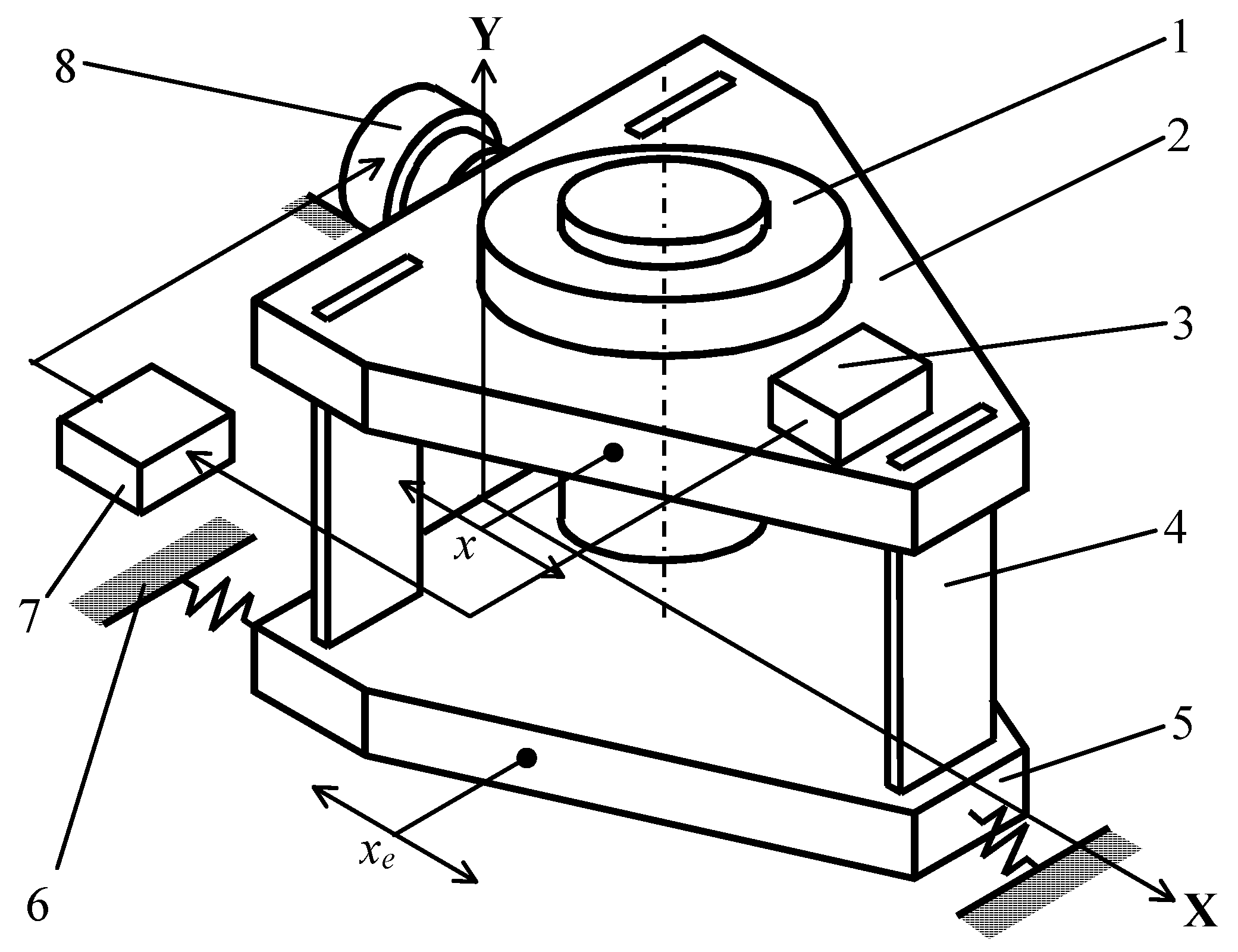
Figure 1. Controlled vibration isolator, (1—object of vibration isolation; 2—moving platform; 3—block of measuring devices; 4—flat springs; 5—conditionally immobile platform; 6—base; 7—feedback unit; 8—electrodynamic vibrator; x and x e —displacement of the moving and conditionally fixed platform relative to the base, respectively).
Asi 07 00095 g001
Figure 2. Diagram of the controlled vibration isolator of a gyro-theodolite.
Asi 07 00095 g002
Figure 3. The influence of LPF and accelerometer dynamics on the stability of the vibration isolator.
Asi 07 00095 g003
Figure 4. The nature of the accelerometer effect on the stability of the vibration isolator.
Asi 07 00095 g004
Figure 5. ARF of an active vibration isolator (ω—frequency of vibration of a limited moving base).
Asi 07 00095 g005
Table 1. Parameters of the gyro-theodolite.
NameValues, Units of Measurement
Gyroscope kinetic momentH = 0. 4 Nms
Mass of the sensing elementm = 1 kg
Distance from the suspension point to the center of massl = 0.1 m
The moment of the SE inertia relative to the X-axis J x = 1.3 × 10 2   kg/m2
The moment of the SE inertia relative to the Y-axis J y = 4 × 10 4   kg/m2
The moment of the SE inertia relative to the Z-axis J z = 1.13 × 10 2   kg/m2
Table 2. Data for AFR construction.
1234567
Re30.34677680.2567493170.117519317−0.1128104−0.4650924−1.02941−1.9377
Im30.365245140.4451387780.5289628680.6083643520.645990820.5762470.245708
M30.503644910.5138761950.5418602270.61873530.795999451.1797231.953217
AFR1.248561331.3494323971.44486861.4736924071.356208411.1052170.81908
891011121314
Re3−3.341773−5.5901633−9.157163183−14.754527−23.65425−37.5−59.403
Im3−0.62738654−2.67948542−7.157731842−16.4854−35.8159026−74.7−153.5
M33.400156126.19915859511.6226831122.1238441542.9220507883.55164.592
AFR0.579739020.3952323710.263037250.1724369930.1110887930.0710.0448
15161718192021
Re3−93.32−146−226−341−503−701.141−873.8
Im3−310.85−626−1259−2497−4954−9765.024−18,956.4
M3324.5526431279252149799790.163218,976.57
AFR0.027990.020.010.0060.0030.00158680.000872
22232425262728
Re3−813.741.72023050.4810,78426,118.899340,284.7−33,862.97
Im3−36,350−67,275−118,566−186,292−213,646.73478,757.481,733,191.7
M336,359.167,275118,605186,604215,237.366488,462.411,733,522.5
AFR0.001160.001770.002580.004020.0084461980.0501610.0062181
29303132333435
Re3−679,340.2−4,177,154−20,303,229.5−91,018,634−383,737,459.7−1,594,343,217−6,480,670,727
Im38,490,859.232,961,875115,645,385.6391,191,215.91,275,274,8904,136,250,33913,227,130,761
M38,517,992.333,225,500117,414,123.3401,640,335.51,331,758,4184,432,888,12914,729,429,087
AFR0.00312070.001990.0014002880.0010303130.0007790860.0005948060.000456499
363738394041
Re3−26,202,029,354−1.06402 × 10¹¹−4.22651 × 10¹¹−1.69342 × 10¹²−6.78923 × 10¹²−2.69315 × 10¹³
Im342,210,027,6871.35384 × 10114.26707 × 10111.35535 × 10124.30869 × 10121.35796 × 1013
M349,681,312,1771.72192 × 10116.00594 × 10112.16902 × 10128.04104 × 10123.01615 × 1013
AFR0.0003497130.0002663460.0002027380.000153670.0001166168.91301 × 10−5
Disclaimer/Publisher’s Note: The statements, opinions and data contained in all publications are solely those of the individual author(s) and contributor(s) and not of MDPI and/or the editor(s). MDPI and/or the editor(s) disclaim responsibility for any injury to people or property resulting from any ideas, methods, instructions or products referred to in the content.