Roughness Effect in Micropitting and Rolling Contact Fatigue of Silicon Nitride

Abstract
:1. Introduction
2. Materials and Methods
2.1. Materials and Surface Conditions
2.2. Tester and Test Procedure
3. Results
3.1. Data Analysis
3.2. RCF Life and Probablity of Failure
4. Discussion
4.1. Role of Peak-to-Valley Roughness in Fatigue
4.2. State of Lubrication and Reduced Film Thickness
5. Conclusions
Author Contributions
Funding
Acknowledgments
Conflicts of Interest
References
- Wang, L.; Snidle, R.W.; Gu, L. Rolling contact silicon nitride bearing technology: A review of recent research. Wear 2000, 246, 159–173. [Google Scholar] [CrossRef]
- Bhandhubanyong, P.; Akhadejdamrong, T. Forming of silicon nitride by the HIP process. J. Mater. Process. Technol. 1997, 63, 277–280. [Google Scholar] [CrossRef]
- Ziegler, A.; Kisielowski, C.; Ritchie, R.O. Imaging of the crystal structure of silicon nitride at 0.8 Angstrom resolution. Acta Mater. 2002, 50, 565–574. [Google Scholar] [CrossRef]
- Hadfield, M.; Stolarski, T.A. The effect of the test machine on the failure mode in lubricated rolling contact of silicon nitride. Tribol. Int. 1995, 28, 377–382. [Google Scholar] [CrossRef]
- Polonsky, I.A.; Chang, T.P.; Keer, L.M.; Sproul, W.D. An analysis of the effect of hard coatings on near-surface rolling contact fatigue initiation induced by surface roughness. Wear 1997, 208, 204–219. [Google Scholar] [CrossRef]
- Miller, G.R.; Keer, L.M.; Cheng, H.S. On the mechanics of fatigue crack growth due to contact loading. Proc. R. Soc. Lond. A 1985, 397, 197–209. [Google Scholar] [CrossRef]
- Mosleh, M.; Bradshaw, K.; Belk, J.H.; Waldrop, J.C., III. Fatigue failure of all-steel and steel-silicon nitride rolling ball combinations. Wear 2011, 271, 2471–2476. [Google Scholar] [CrossRef]
- Ås, S.K.; Skallerud, B.; Tveiten, B.W. Surface roughness characterization for fatigue life predictions using finite element analysis. Int. J. Fatigue 2008, 30, 2200–2209. [Google Scholar] [CrossRef]
- Westkaemper, E.; Hoffmeister, H.W. Function-oriented lapping and polishing of ceramic rolling elements through characterization of the workpiece surface. CIRP Ann. Manuf. Technol. 1996, 45, 529–532. [Google Scholar] [CrossRef]
- Effner, U.; Woydt, M. Importance of machining on tribology of lubricated slip-rolling contacts of Si3N4, SiC, Si3N4–TiN and ZrO2. Wear 1998, 216, 123–130. [Google Scholar] [CrossRef]
- Westkaemper, E.; Hoffmeister, H.W. Function-oriented surface characterization of lapped and polished ceramic rolling elements. In Proceedings of the 7th International Conference on Metrology and Properties of Engineering Surfaces, Gothenburg, Sweden, 2–4 April 1997; pp. 432–443. [Google Scholar]
- Li, S.; Kahraman, A. Micro-pitting fatigue lives of lubricated point contacts: Experiments and model validation. Int. J. Fatigue 2013, 48, 9–18. [Google Scholar] [CrossRef]
- Li, S.; Kahraman, A.; Klein, M. A fatigue model for spur gear contacts operating under mixed elastohydrodynamic lubrication conditions. ASME J. Mech. Des. 2012, 134, 11. [Google Scholar] [CrossRef]
- Britton, R.D.; Elcoate, C.D.; Alanou, M.P.; Evans, H.P.; Snidle, R.W. Effect of surface finish on gear tooth friction. ASME J. Tribol. 2000, 122, 354–360. [Google Scholar] [CrossRef]
- Batista, A.C.; Dias, A.M.; Lebrun, J.L.; Le Flour, J.C.; Inglebert, G. Contact fatigue of automotive gears: Evolution and effects of residual stresses introduced by surface treatments. Fatigue Fract. Eng. Mater. Struct. 2000, 23, 217–228. [Google Scholar] [CrossRef]
- Moorthy, V.; Shaw, B.A. An observation on the initiation of micro-pitting damage in as-ground and coated gears during contact fatigue. Wear 2013, 297, 878–884. [Google Scholar] [CrossRef]
- Kanga, J.; Hadfielda, M.; Cundillb, R.T. Rolling contact fatigue performance of HIPed Si3N4 with different surface roughness. Ceram. Int. 2001, 27, 781–794. [Google Scholar] [CrossRef]
- Lv, B.H.; Chen, L.N.; Zhao, P.; Chang, M. Study on Fixed Abrasive Lapping Technology for Ceramic Balls. Mater. Sci. Forum. 2006, 532, 460–463. [Google Scholar] [CrossRef]
- Yuan, J.L.; Lü, B.H.; Lin, X.; Zhang, L.B.; Ji, S.M. Research on abrasives in the chemical–mechanical polishing process for silicon nitride balls. J. Mater. Process. Technol. 2002, 129, 171–175. [Google Scholar] [CrossRef]
- Umehara, N.; Kirtane, T.; Gerlick, R.; Jain, V.K.; Komanduri, R. A new apparatus for finishing large size/large batch silicon nitride (Si3N4) balls for hybrid bearing applications by magnetic float polishing (MFP). Int. J. Mach. Tools Manuf. 2006, 46, 151–169. [Google Scholar] [CrossRef]
- Hah, S.R.; Fischer, T.E. Tribochemical Polishing of Silicon Nitride. J. Electrochem. Soc. 1998, 145, 1708–1714. [Google Scholar] [CrossRef]
- Zaretsky, E.V. Bearing Elastohydrodynamic Lubrication: A Complex Calculation Made Simple; NASA Technical Memorandum; NASA: Washington, DC, USA, 1990.
- Tourret, R.; Wright, E.P. Rolling Contact Fatigue: Performance Testing of Lubricants; Heyden and Son LTD: London, UK, 1977. [Google Scholar]
- Mosleh, M.; Bradshaw, K. Role of component configuration in evaluation of accelerated rolling contact fatigue of ball bearings. Wear 2011, 271, 2681–2686. [Google Scholar] [CrossRef]
- Murthy, D.N.P.; Bulmerc, M.; Eccleston, J.A. Weibull model selection for reliability modeling. Reliab. Eng. Syst. Saf. 2004, 86, 257–267. [Google Scholar] [CrossRef]
- Moltoft, J. Statistical analysis of data from electronic component life tests (A tutorial paper). Act. Passiv. Electron. Compon. 1987, 12, 259–279. [Google Scholar] [CrossRef]
- Sadeghi, F.; Jalalahmadi, B.; Slack, T.S.; Raje, N.; Arakere, N.K. A review of rolling contact fatigue. J. Tribol. 2009, 131, 1–15. [Google Scholar] [CrossRef]
- Arakere, N.K.; Branch, N.; Levesque, G.; Svendsen, V.; Forster, N.H. Rolling Contact Fatigue Life and Spall Propagation of AISI M50, M50NiL, and AISI 52100, Part II: Stress Modeling. Tribol. Trans. 2009, 53, 42–51. [Google Scholar] [CrossRef]


| Properties | AISI 52100 | Silicon Nitride |
|---|---|---|
| Hardness (Rc) | 60–67 | 76–80 |
| Diameter (mm) | 12.7 | 12.7 |
| Modulus (GPa) | 210 | 310 |
| Poisson’s ratio | 0.3 | 0.26 |
| Density (g/cm3) | 7.81 | 3.27 |
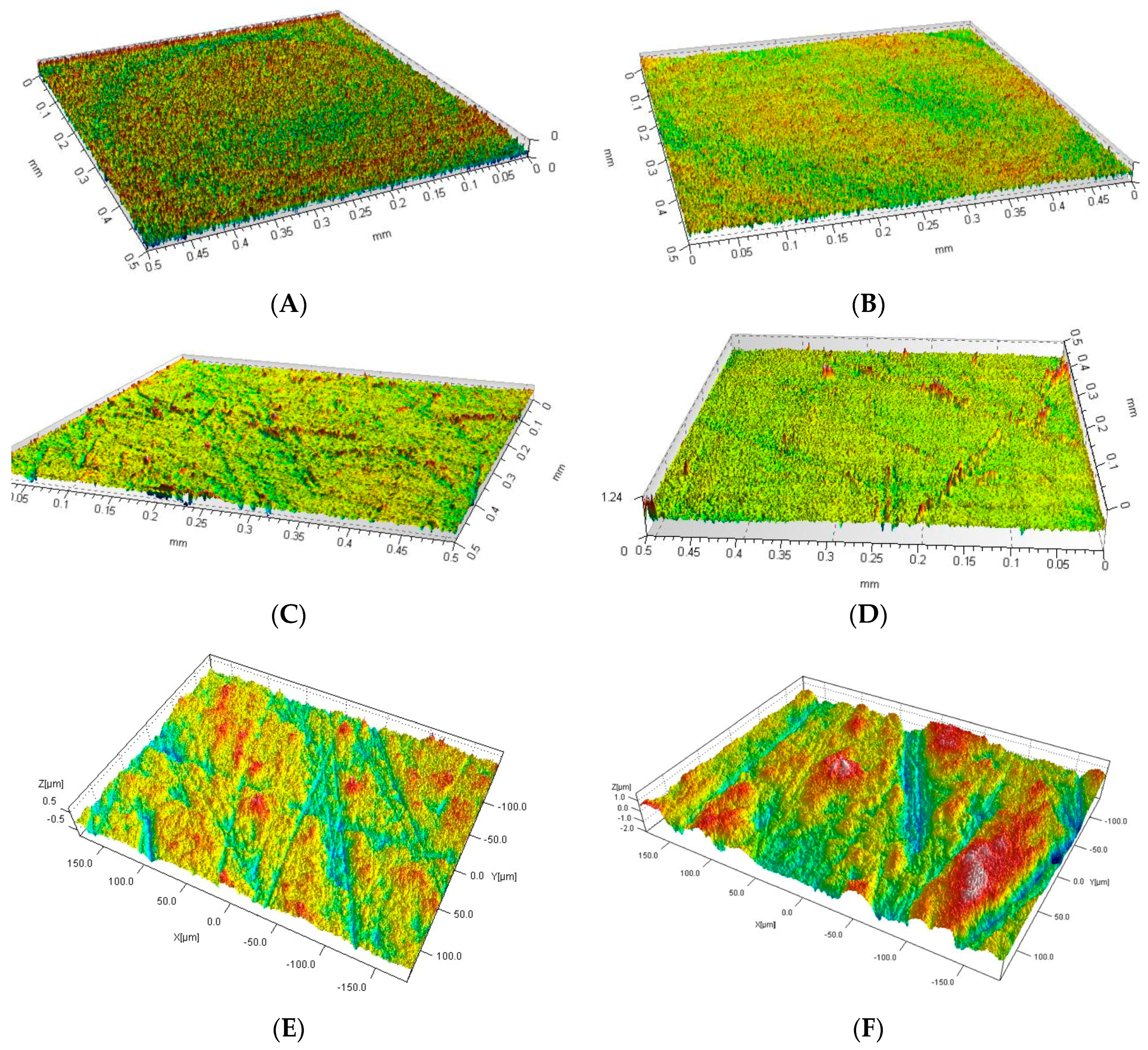
| Sample ID | Diameter (mm) | Rz (μm) | Ra (μm) | Rq (μm) |
|---|---|---|---|---|
| A (original finish) | 12.7 | 0.312 | 0.030 | 0.039 |
| B | 12.7 | 0.388 | 0.026 | 0.033 |
| C | 12.7 | 0.961 | 0.052 | 0.074 |
| D | 12.7 | 1.259 | 0.043 | 0.068 |
| E | 12.7 | 1.578 | 0.117 | 0.148 |
| F | 12.7 | 3.720 | 0.356 | 0.452 |
| Sample ID | (EHL “Reduced” Film Thickness) |
|---|---|
| A | 1.06 |
| B | 0.99 |
| C | 0.57 |
| D | 0.46 |
| E | 0.37 |
| F | 0.16 |
© 2019 by the authors. Licensee MDPI, Basel, Switzerland. This article is an open access article distributed under the terms and conditions of the Creative Commons Attribution (CC BY) license (http://creativecommons.org/licenses/by/4.0/).
Share and Cite
Mosleh, M.; Bradshaw, K.K.; Smith, S.T.; Belk, J.H.; Shirvani, K.A. Roughness Effect in Micropitting and Rolling Contact Fatigue of Silicon Nitride. Ceramics 2019, 2, 135-147. https://doi.org/10.3390/ceramics2010013
Mosleh M, Bradshaw KK, Smith ST, Belk JH, Shirvani KA. Roughness Effect in Micropitting and Rolling Contact Fatigue of Silicon Nitride. Ceramics. 2019; 2(1):135-147. https://doi.org/10.3390/ceramics2010013
Chicago/Turabian StyleMosleh, Mohsen, Keron K. Bradshaw, Sonya T. Smith, John H. Belk, and Khosro A. Shirvani. 2019. "Roughness Effect in Micropitting and Rolling Contact Fatigue of Silicon Nitride" Ceramics 2, no. 1: 135-147. https://doi.org/10.3390/ceramics2010013
APA StyleMosleh, M., Bradshaw, K. K., Smith, S. T., Belk, J. H., & Shirvani, K. A. (2019). Roughness Effect in Micropitting and Rolling Contact Fatigue of Silicon Nitride. Ceramics, 2(1), 135-147. https://doi.org/10.3390/ceramics2010013