Article

Improvement in Slag Resistance of No-Cement Refractory Castables by Matrix Design

1
Elkem Silicon Materials, 4675 Kristiansand, Norway
2
Wuhan University of Science and Technology, Wuhan 430081, China
*
Author to whom correspondence should be addressed.
Ceramics 2020, 3(1), 31-39; https://doi.org/10.3390/ceramics3010004
Submission received: 26 November 2019 / Revised: 28 December 2019 / Accepted: 7 January 2020 / Published: 11 January 2020
(This article belongs to the Special Issue Design, Properties, Damage and Lifetime of Refractory Ceramics)

Abstract

:
The corrosion resistance of spinel containing cement bonded castables has been extensively investigated in the past. However, corrosion of no-cement refractory castables (NCC) has not been widely studied since the use of NCC has been relatively limited up till now. This paper focuses on the slag resistance of NCCs, and the often-used spinel containing low cement castable (LCC) is used as the reference. Three different NCC binders were designed: (i) Al2O3 + MgO (alumina bond), in situ spinel formation; (ii) Al2O3 + SiO2 (microsilica-gel bond), mullite formation; and (iii) Al2O3 + MgO + SiO2 (MgO-SiO2 bond). Slag resistance tests were conducted using the static crucible method with ladle slag. The corrosion mechanisms were studied by means of Scanning Electron Microscopy (SEM/EDS), X-ray Diffraction (XRD), and thermodynamic simulations. The results confirmed that the mineral phases, microstructure, and liquid formation at a high temperature of the refractory materials had a strong impact on the corrosion resistance. The slag resistance was significantly improved when the cement was replaced by the cement-free binders.

1. Introduction

Due to the excellent corrosion resistance to basic slags and good thermo-mechanical properties, either in situ forming or pre-formed spinel (MgAl2O4) containing cement bonded refractory castables (low cement castables (LCCs)) have been widely used for steel ladles [1]. Many publications have also highlighted that the in-situ spinel forming LCCs exhibit better slag resistance compared to the pre-formed spinel containing LCCs due to the fine and well distributed spinel grains derived from the reaction between MgO and Al2O3 during sintering. For castables containing in situ formed spinel, the Fe2+, Fe3+, and Mn2+ (from slag) can be entrapped in the crystal lattice of the spinel via solid solution; the CaO (from slag) reacts with Al2O3 fines to form calcium aluminate (e.g., CA2 and CA6) [2,3], resulting in improved slag resistance.
The major challenge for in situ spinel forming LCCs is crack formation due to volumetric expansion. The expansive behavior is commonly caused by: (i) MgO hydration during curing and dry-out stage and (ii) in situ spinel formation and formation of calcium hex-aluminate (CA6) at high temperatures. To overcome these problems, small amounts of microsilica are often added, e.g., 0.5–1.0%. The addition of microsilica gives several benefits: (i) microsilica can improve the flow and reduce the water demand of the castable; (ii) the MgO hydration/brucite formation is inhibited by forming magnesia-silicate hydrate on the surface of the MgO, thus preventing crack formation; (iii) microsilica will react with CaO and Al2O3 to form low melting phases during sintering, such as gehlenite (Ca2Al2SiO7-C2AS) or anorthite (CaAl2Si2O8-CAS2), to counteract the volumetric expansion caused by spinel formation. This low melting liquid formation can also speed up the spinel formation. Still, the perception in the refractory industry is that this low melting liquid is detrimental to hot properties such as the hot modulus of rupture (HMOR) and refractoriness under load (RUL) and that it will impair the service life at high temperatures [4,5,6]. In order to further improve the performance at high temperatures, silica-free or cement-free spinel castables seem to have potential.
Calcium aluminate cement (CAC) is by far the most used binder in Al2O3-MgO refractory castable formulations and the corrosion resistance of spinel containing cement bonded castables has been extensively investigated [7,8,9]. Since the use of no-cement refractory castables (NCCs) has been relatively limited, corrosion of NCC has not yet been widely studied. The objective of this paper is to examine and understand the corrosion mechanism of alternative NCC binders. Three binders were designed: (i) Al2O3 + MgO (alumina bond), in situ spinel formation; (ii) Al2O3 + SiO2 (microsilica-gel bond), mullite formation; and (iii) Al2O3 + MgO + SiO2 (MgO-SiO2 bond). The test results show that cement-free castables outperform the pre-formed spinel containing LCC in terms of corrosion resistance. Of the tested NCC binders, the two component binders, alumina bond and microsilica-gel bond, showed better corrosion resistance than the triple mix binder, MgO-SiO2 bond.

2. Materials and Methods

2.1. Composition Design

Table 1 shows the composition of the NCC castables. The pre-formed spinel containing cement bonded castable (labelled LCC-SP) was chosen as a reference mix in which no microsilica was added. The cement content was 7.0 wt%. Tabular alumina (T60, Almatis, Ludwigshafen am Rhein Germany) and alumina rich spinel (AR 78, Almatis, Ludwigshafen am Rhein Germany) were used as aggregates. Alumina fines, as well as a new spherical alumina (AloxX-Spheres 99, Elkem, Oslo Norway), magnesia fines, microsilica (Elkem Microsilica 971U, Elkem, Oslo Norway), SioxX-Zero and SioxX-Mag (Elkem, Oslo, Norway), and calcium aluminate cement (CAC, 70% Al2O3) were used in the matrix. SioxX-Zero and SioxX-Mag are tailored products for microsilica-gel bonded and MgO containing NCCs, respectively. As shown in Table 1, three types of binders of tabular alumina based NCCs were designed: (i) Al2O3 + MgO (alumina bond), (ii) Al2O3 + SiO2 (microsilica-gel bond), and (iii) Al2O3 + MgO + SiO2 (MgO-SiO2 bond). They were labelled NCC-1, NCC-2, and NCC-3, respectively. For NCC-1, with no microsilica, the maximum MgO content was 3%. If more MgO were added, cracking would occur after demolding/drying.

2.2. Sample Preparation and Characterization

The dry components were mixed using a Hobart mixer for four minutes at 60 RPM; water was added, and the castable was wet mixed for an additional four minutes. Self-flow and vibration flow were measured after four minutes of wet mixing using the flow cone described in ASTM C230 (height 50 mm, self-flow cone described in EN 1402-4:2003). The flow value is the percentage increase of the diameter measured 90 seconds after removing the cone. The molds were kept at 20 °C in >90% RH for 24 h before demolding. The cold modulus of rupture (CMOR) and cold crushing strength (CCS) after drying at 110 °C for 24 h were measured.
Cylindrical specimens (“crucibles”) and a ladle slag from a steel plant (Table 2) were used in the static corrosion resistance cup test, also called the crucible test. The dimensions of the crucibles were: (i) external diameter 85 mm, (ii) height 85 mm, and (iii) the central inner cavity 44 mm in diameter and 44 mm in depth. After casting, the samples were kept in the molds for 24 h, then demolded and dried at 110 °C for 24 h. Before the slag resistance test, the crucibles were fired at 1100 °C for 5 h.
For the static corrosion resistance test, the pre-heated crucibles were filled with cold ladle slag and fired at 1550 °C for 4 h. After cooling, the crucibles were cut for further examination. The “corroded area percentage” (CAP) after the test was calculated as described in Figure 1a. Samples were cut and had their cross-sections polished and prepared for further characterization as marked in Figure 1b. SEM/EDS (Quanta 400, FEI Company, Hillsboro, OR, USA) and XRD with CuKα radiation (x’Pert Pro, Philips, Amsterdam, Netherlands) were used for the analyses.
To further understand the corrosion mechanism, the viscosity of the formed liquid from the interaction between the slag and the refractories was predicted/simulated using the viscosity modules in the FactSage 6.2 software package (Thermfact/CRCT, Montreal, Canada) in combination with the Gibbs energy minimization method and equilibrium module. The thermodynamic calculations were done for the matrix, since the corrosion reaction mainly took place in the matrix. The ratio of the matrix to the total castable composition was assumed at 40 wt% for all mixes, and the selected matrix compositions are shown in Table 3. For the viscosity calculation of molten liquid, 100 g of total slag was used. The mass ratio of matrix to slag was termed “Beta”. When Beta was 0.5, the 50 g matrix reacted with 100 g slag. All calculations were done assuming a constant temperature of 1600 °C and a pressure of 1 atm.

3. Results and Discussion

3.1. Wet-Out Time, Flow, and Mechanical Properties

The wet-out time, self-flow, vibration flow, and mechanical properties are summarized in Table 4. The water addition of NCC-1, NCC-2, and NCC-3 was 4.25–4.5%, and the wet-out time was less than 30 s. The water addition of LCC-SP was 5.0%. At 4.7% water addition, the LCC-SP wet mix showed dilatant behavior, and the wet-out time was more than 120 s. Among the NCCs, NCC-2 containing SioxX-Zero had the highest flow, with a self-flow value of 80%, while the other two were around 60%.
As shown in Table 4, both CCS and CMOR of LCC-SP were higher than the NCCs. Among the NCCs, NCC-3 containing Al2O3 + MgO + SiO2 binder had the highest strength, with CCS of 110.1 MPa and CMOR of 14.7 MPa. NCC-1 with Al2O3 + MgO binder showed the lowest strength, with CCS and CMOR of merely 16.1 MPa and 3.7 MPa, respectively. The high strength of NCC-3 was probably attributed both to the microsilica-gel bond and magnesium hydrate silicate bond (M-S-H) developed during the curing and drying process [10].

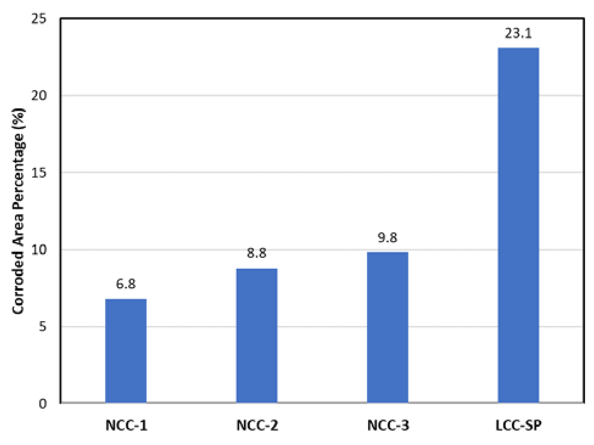
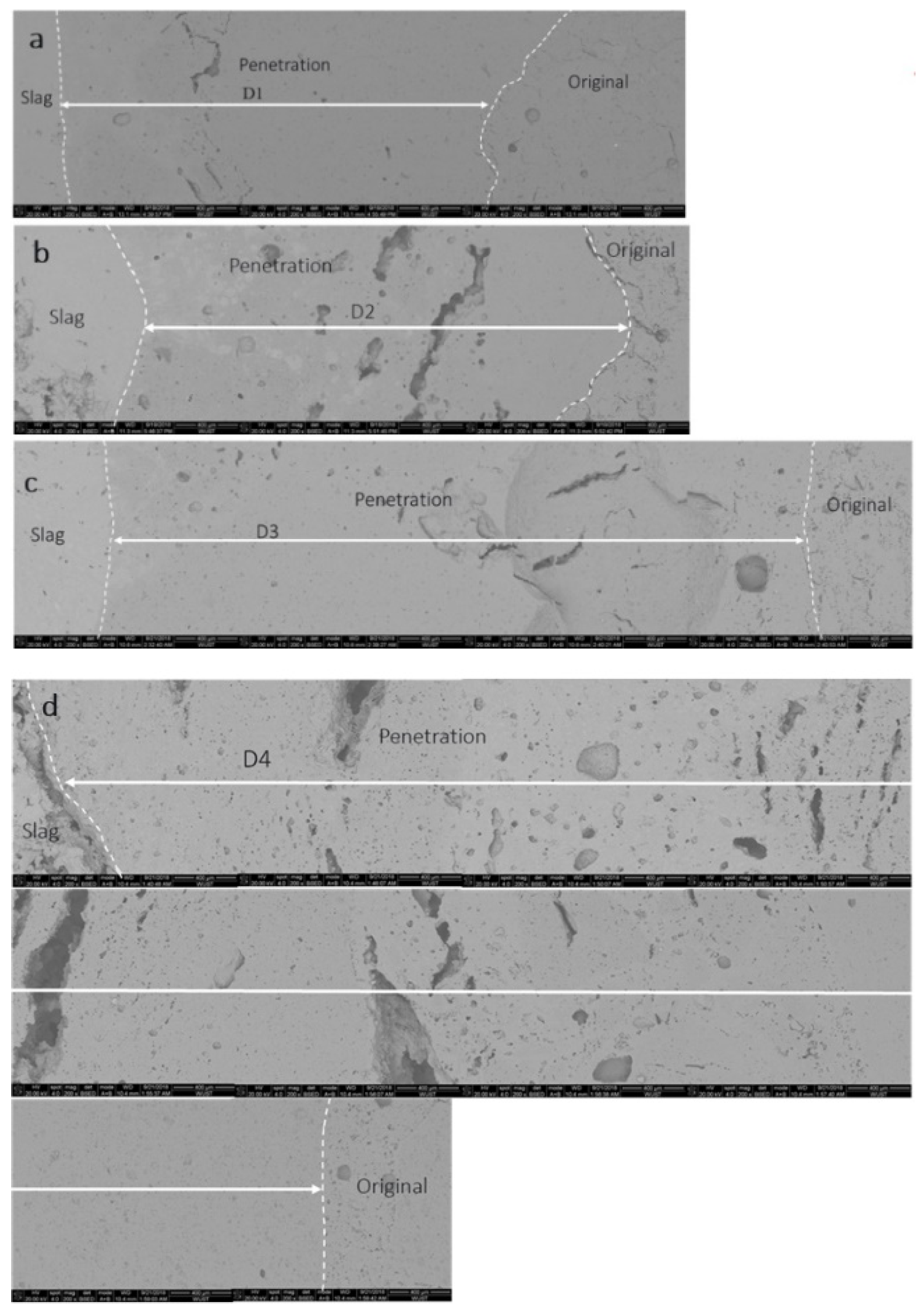
3.2. Corrosion Cup Test

Figure 2 and Figure 3 show the cross-sections of the corroded samples and the calculated corroded areas (CAP), respectively. The dotted line indicates the original dimensions of the inner cup. The LCC-SP had by far the highest CAP (up to 23.1%), and its matrix seemed to be washed out, leaving aggregates surrounded by the slag.
In contrast, the NCC series showed much better corrosion resistance. As shown in Figure 3, the corrosion area percentages of samples NCC-1, NCC-2, and NCC-3 were 6.8%, 8.8%, and 9.8%, respectively. This indicated that the NCC sample with in situ spinel formation (NCC-1 containing MgO) or mullite formation (NCC-2 containing microsilica) showed relatively good slag resistance. However, when the binders contained both MgO and microsilica, the corrosion resistance would deteriorate, which was probably due to liquid formation and the weak bond.

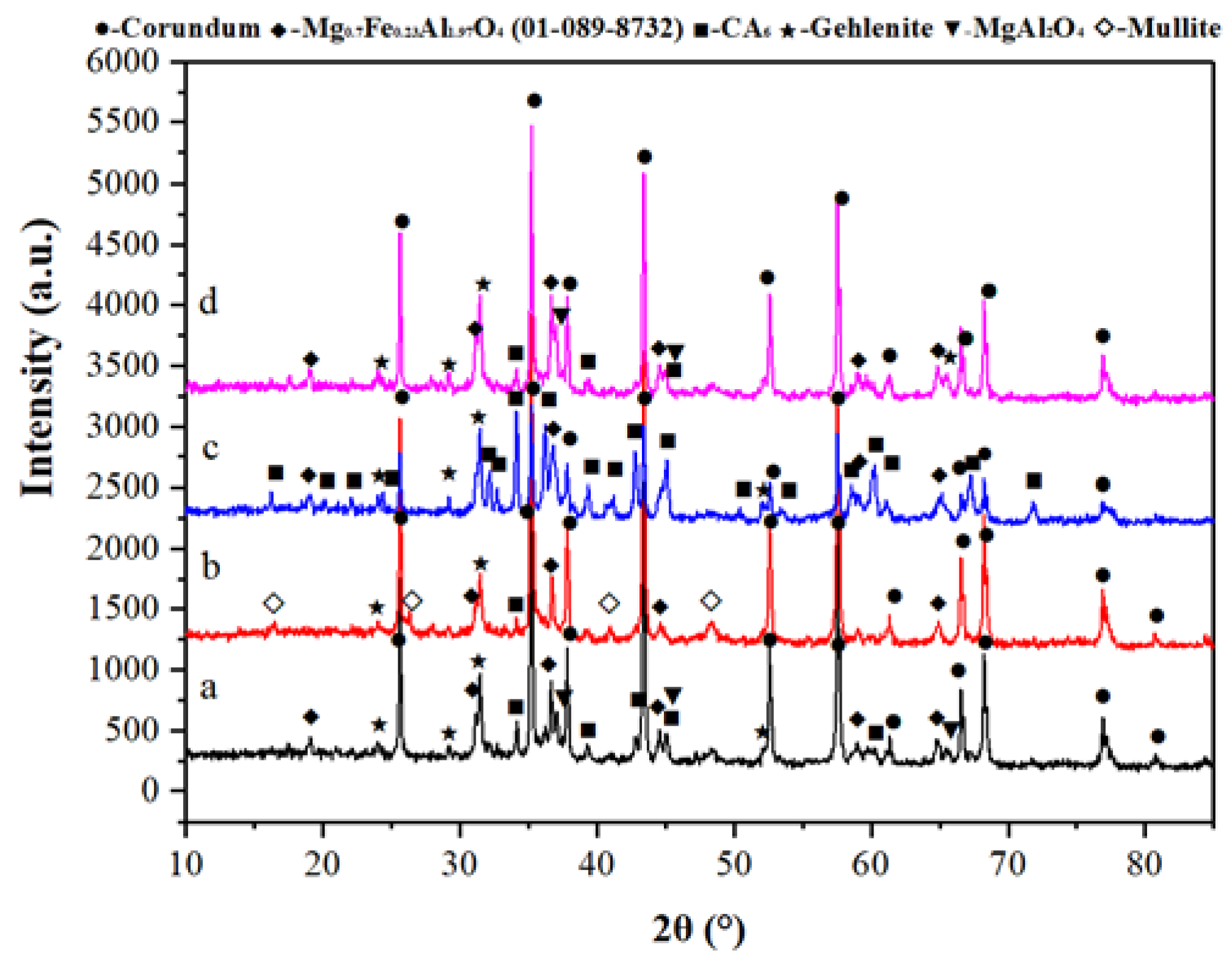
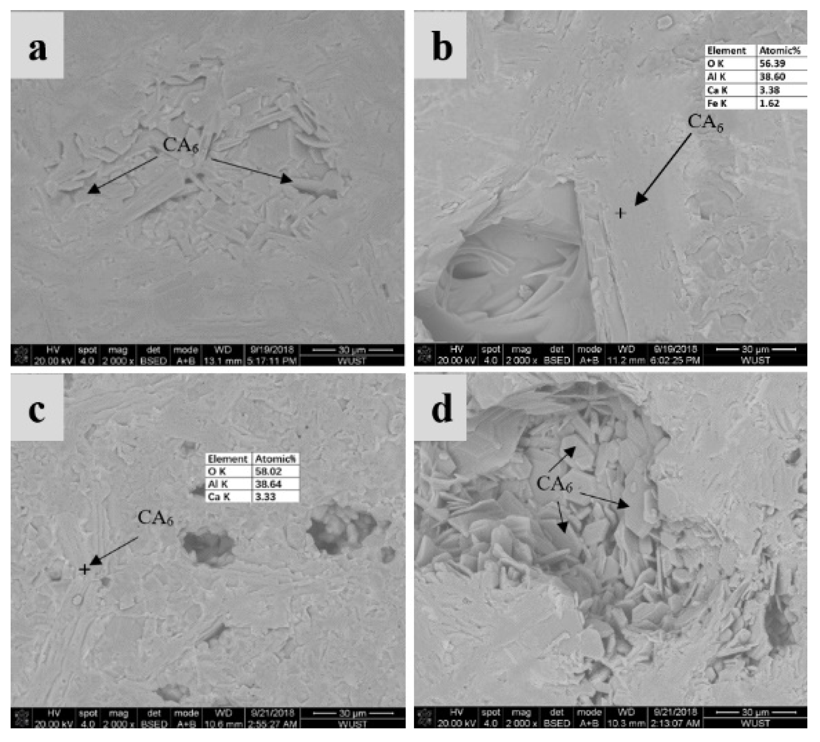
3.3. SEM and XRD Characterization

The SEM images of the slag zone, penetration zone, and original refractory are presented in Figure 4. D1, D2, D3, and D4 are the penetration depths in NCC-1, NCC-2, NCC-3, and LCC-SP, respectively. The penetration depth increased in the following order: D1 < D2 < D3 < D4. As seen in Figure 4, the penetration depths in the NCCs were slightly different when different no-cement binders were used, but they were all at a comparable level. NCC-2 and NCC-3 showed a slightly larger penetration depth than NCC-1, which was probably due to the introduction of microsilica. What was surprising was that the penetration in LCC-SP was approximately four times deeper than that in NCC-1. These SEM observations were in good agreement with the calculated corroded areas (Figure 3).
Figure 5 shows the XRD analyses of the samples after the corrosion cup test. For NCC-2, where the binder consisted of Al2O3 and SiO2 (microsilica) only, mullite was, as expected, formed after firing at 1550 °C besides Calcium Hexaluminate (CA6) and spinel solid solution (Fe). For the other three castables in which MgO and/or pre-formed spinel were/was added, the mineral phases observed were spinel, spinel solid solution (MgAl2O4 + MgFe2O4), gehlenite (Ca2Al2SiO7-C2AS), and CA6. It was clearly seen that the intensity of the diffraction peak for each phase varied with the variation of binder composition. For example, the intensity of the peaks of CA6 and gehlenite for LCC-SP were much higher than that of NCCs. This was attributed to the massive CA6 formation from the CAC.
In order to ascertain the phase distribution in the slag and penetration zones, SEM/EDS analyses were further carried out (Figure 6). Spinel and spinel solid solution (MgAl2O4 + MgFe2O4 containing MnO) were observed in all specimens no matter if the starting composition contained MgO or not. This indicated that the Mg2+ in the slag reacted with the alumina in the refractory to form spinel. In addition, gehlenite (C2AS) was also seen due to the interaction between Si, Ca from the slag, and alumina in the refractory matrix. For the LCC-SP, although the pre-formed spinel was used in the composition, a newly formed octahedral spinel phase could still be seen in the corroded zone (as shown in Figure 5d), mainly formed by the reaction between MgO in the slag and the alumina in the refractory. Furthermore, the use of CAC resulted in the formation of large amounts of gehlenite, which would convert to the liquid phase at high temperatures and exacerbate the corrosion and penetration. This explains why LCC-SP had the lowest resistance to slag attack.
SEM images and EDS analyses of the penetration zones are presented in Figure 7. CA6 phases were observed in the NCCs even though there were no or only trace amounts of Ca2+ available in the refractory composition. This confirmed that CaO in the slag penetrated the refractory and reacted with alumina to form CA6. For LCC-SP, a massive CA6 formation was again observed, which was attributed to both the phase transformation from CAC and the interaction between CaO in the slag and alumina from the refractory.
The corrosion mechanism of the ladle slag involved the following reactions: (i) part of the Mg2+ and Fe3+ from the slag reacted with alumina in the refractory to form spinel solid solution, (ii) Si4+ and Ca2+ penetrated the refractory and reacted with alumina in the refractory to form gehlenite (C2AS); (iii) Ca2+ from the slag reacted with alumina in the refractory to from CA6; and (iv) last but not least, liquid formation due to the interaction between the slag and the refractory body. The formation of CA6 and spinel solid solution (Fe) contributed to the improved corrosion resistance of NCCs, whereas the formation of gehlenite (C2AS) led to deteriorating slag resistance of the refractory castable at high temperatures.

3.4. Thermodynamic Simulation

It is well known that the viscosity of the molten slag and the liquid formed during the interaction between the slag and the refractory body had a significant impact on the penetration. The higher the viscosity, the more difficult it was to penetrate the refractory. Figure 8 shows the estimated viscosity of the liquid generated at 1600 °C during the slag–matrix interaction. It was observed that the viscosity of the liquid phase in all samples increased with the increase of Beta. At a given Beta value, NCC-2 (microsilica-gel bond) presented the highest viscosity, followed by NCC-3 (M-S-H bond). The estimated viscosity of the liquid indicated that the introduction of microsilica could increase the viscosity, contributing to an improved penetration resistance. In contrast, the cement bonded.
LCC-SP presented the lowest viscosity, indicating that the molten slag could more easily penetrate the refractory. Again, this explained why LCC-SP showed inferior slag resistance compared to NCCs.

4. Conclusions

Based on the obtained results from the corrosion cup test, SEM and XRD characterization of the corroded zones, and the viscosity simulation of the molten slag, the following conclusions can be drawn.
  • Selection of the optimal type of binder was a key factor in refractory design. All three types of tested NCCs outperformed the LCC with pre-formed spinel in terms of corrosion resistance against the tested ladle slag.
  • CAC binder would not only produce a large amount of liquid phase, but also lead to a lowering of the viscosity. Consequently, the resistance to slag penetration in the LCC-SP was inferior to the NCCs.
  • The no-cement binders composed of Al2O3 + MgO (alumina bond with in situ spinel formation) and Al2O3 + SiO2 (microsilica-gel bond with mullite formation) showed better corrosion resistance than the magnesium silicate hydrate (M-S-H) bonded NCC.
  • The viscosity of the liquid formed during the interaction between the slag and the refractory had a strong impact on the corrosion resistance. The viscosity increased with the increase of microsilica addition, contributing to better penetration resistance.

Author Contributions

Experimental design and preparation, H.P.; Analysis and characterization/SEM, XRD and thermodynamic calculation, J.L. and Q.W.; writing—original draft preparation, H.P. and J.L.; writing—review and editing, Q.W. and Y.L.; supervision, H.P., Q.W. and Y.L. All authors have read and agreed to the published version of the manuscript.

Funding

This research received no external funding.

Acknowledgments

The authors wish to thank Andrea Alfano for assisting specimen preparation and test and Terje Nilsen for English editing.

Conflicts of Interest

The authors declare no conflict of interest.

References

  1. Sako, E.; Braulio, M.; Pandolfelli, V. The corrosion and microstructure relationship for cement-bonded spinel refractory castables. Ceram. Int. 2012, 38, 2177–2185. [Google Scholar] [CrossRef]
  2. Nakagawa, Z.; Enomoto, N.; Yi, I.S.; Asano, K. Effect of corundum periclase sizes on expansion behaviour during synthesis of spinel. In Proceedings of the UNITECR’95, Kyoto, Japan, 19–22 November 1995; pp. 1312–1319. [Google Scholar]
  3. Rigaud, M.; Palco, S.; Wang, N. Spinel formation in the MgO-Al2O3 system relevant to basic oxides. In Proceedings of the UNITECR’95, Kyoto, Japan, 19–22 November 1995; pp. 387–394. [Google Scholar]
  4. Carter, R.E. Mechanism of solid-state reaction between magnesium oxide and aluminum oxide and between magnesium oxide and ferric oxide. J. Am. Ceram. Soc. 1997, 44, 116–120. [Google Scholar] [CrossRef]
  5. Korgul, P.; Wilson, D.; Lee, W. Microstructural analysis of corroded alumina-spinel castable refractories. J. Eur. Ceram. Soc. 1997, 17, 77–84. [Google Scholar] [CrossRef]
  6. Braulio, M.; Rigaud, M.; Buhr, A.; Parr, C.; Pandolfelli, V. Spinel-containing alumina-based refractory castables. Ceram. Int. 2011, 37, 1705–1724. [Google Scholar] [CrossRef]
  7. Luz, A.P.; Braulio, M.A.L.; Martinez, A.G.T.; Pandolfelli, V. Slag attack evaluation of in situ spinel-containing refractory castables via experimental tests and thermodynamic simulations. Ceram. Int. 2012, 38, 1497–1505. [Google Scholar] [CrossRef]
  8. Martinez, A.T.; Luz, A.; Braulio, M.; Pandolfelli, V. Al2O3-based binders for corrosion resistance optimization of Al2O3-MgAl2O4 and Al2O3-MgO refractory castables. Ceram. Int. 2015, 41, 9947–9956. [Google Scholar] [CrossRef]
  9. Schnabel, M.; Buhr, A.; Exenberger, R.; Rampitsch, C. Spinel: In situ versus preformed—clearing the myth. Refract. Worldforum 2010, 2, 87–93. [Google Scholar]
  10. Myhre, B.; Peng, H. The hydration behaviour of MgO-SiO2-H2O gel bonded MgO castables. Refract. Worldforum 2015, 7, 95–100. [Google Scholar]
Figure 1. (a) Calculation of CAP (corroded area percentage) and (b) sections for SEM and XRD characterization.
Ceramics 03 00004 g001
Figure 2. Cross-sections of the corroded samples. (a) NCC-1, (b) NCC-2, (c) NCC-3, and (d) LCC-SP. The dotted line indicates the original inner cup dimensions.
Ceramics 03 00004 g002
Figure 3. Corrosion area percentage (%) of corroded samples after carrion cup-test.
Ceramics 03 00004 g003
Figure 4. SEM micrographs of polished cross-sections of the corroded specimens. (a) NCC-1, (b) NCC-2, (c) NCC-3, and (d) LCC-SP.
Ceramics 03 00004 g004
Figure 5. XRD analyses. (a) NCC-1, (b) NCC-2, (c) NCC-3, and (d) LCC-SP.
Ceramics 03 00004 g005
Figure 6. SEM of the interface between the slag and the penetration zone. (a) NCC-1, (b) NCC-2, (c) NCC-3, and (d) LCC-SP.
Ceramics 03 00004 g006
Figure 7. SEM of the penetration zone. (a) NCC-1, (b) NCC-2, (c) NCC-3, and (d) LCC-SP.
Ceramics 03 00004 g007
Figure 8. Estimated viscosity of liquid generated at 1600 °C during the slag–matrix interaction. The mass ratio of matrix to slag is termed “Beta”.
Ceramics 03 00004 g008
Table 1. Overall composition. NCC, no-cement refractory castable; LCC, low cement castable; SP, spinel.
Wt%NCC-1NCC-2NCC-3LCC-SP
Tabular 0–5 mm79.182.579.752.2
Spinel AR 78 0–1 mm 24.9
Calcined alumina fines4.99.53.415.4
Calcium aluminate cement (70% Al2O3)0.5 7.0
Spherical alumina fines12.6 8.70.5
MgO (325 mesh)2.9 3.9
Elkem MS971U 5.02.4
SioxX-Zero 3.0
SioxX-Mag 2.0
Water %4.14.44.35.0
Table 2. Chemical composition of the industrial produced slag.
(wt%)CaO/SiO2 massSiO2Al2O3Fe2O3CaOMgOK2ONa2OTiO2MnO
Slag1.4716.432.6215.424.16.10.070.40.353.15
Table 3. Compositions used for viscosity simulation.
wt%Al2O3MgOSiO2CaO
NCC-192.17.5 0.5
NCC-282.50.117.5
NCC-382.5107.5
LCC-SP8013.8 6.2
Table 4. Wet-out time, flow, and mechanical properties. CMOR, cold modulus of rupture; CCS, cold crushing strength.
SampleNCC-1NCC-2NCC-3LCC-SP
Self-flow (%)548060152
Vibration-flow (%)124124120172
110 °C/24 h
CMOR3.686.2614.817.3
CCS16.138.7110.1151.4

