Abstract
The objective of this study is to explore and compare the mechanical response of AlCrSiN coatings deposited on two different substrates, namely, WC-Co and cBN. Nano-indentation was used to measure the hardness and elastic modulus of the coatings, and micro-indentation was used for observing the contact damage under Hertzian contact with monotonic and cyclic (fatigue) loads. Microscratch and contact damage tests were also used to evaluate the strength of adhesion between the AlCrSiN coatings and the two substrates under progressive and constant loads, respectively. The surface damages induced via different mechanical tests were observed using scanning electron microscopy (SEM). A focused ion beam (FIB) was used to produce a cross-section of the coating–substrate system in order to further detect the mode and extent of failure that was induced. The results show that the AlCrSiN coating deposited on the WC-Co substrate performed better in regard to adhesion strength and contact damage response than the same coating deposited on the cBN substrate; this is attributed to the lower plasticity of the cBN substrate as well as its less powerful adhesion to the coating.
Keywords:
AlCrSiN; quaternary coating; WC-Co; cBN; nano-indentation; microscratch; adhesion strength 1. Introduction
Hard protective coatings are frequently used in the tool industry to improve wear and corrosion resistance [1,2]. Based on traditional binary metal nitride ceramic coatings (such as CrN and TiN), aluminum (Al) and silicon (Si) are introduced to form quaternary coating systems (AlCrSiN and AlTiSiN) with enhanced mechanical properties, thermal stability, and wear resistance [3,4]. By adding Al and Si, an oxide-rich layer is formed on top, contributing to improved oxidation resistance and thermal stability of the coating [5,6]. In addition, the amorphous Si3N4 phase formed in the grain boundary inhibits the neighboring grains from sliding, which results in better hardness and thermal stability [7,8,9].
These coatings are normally deposited via physical vapor deposition (PVD) [10,11]. The crystalline phase coatings consist of a face-centered cubic lattice with high atomic density formed via crystallization of a metastable amorphous phase after thermal treatment, producing a coating with a columnar structure [12,13,14].
Although the mechanical properties of these coatings have been studied before [15], information about mechanical behavior when the coatings are deposited on different substrates is scarce. Performance of tool materials is governed by both the coating and the substrate, which may result in very different performances even for the same coating if the substrate is different. The two most used hard substrates in the coating industry are hardmetals (also known as cemented carbides) and cubic boron nitride.
Hardmetals are composed of a hard WC phase bonded with a metal, usually cobalt (WC-Co), presenting an outstanding combination of mechanical properties including hardness, fracture toughness, and wear resistance [16,17]. Cubic boron nitride (cBN) is a superhard material consisting of cBN particles bonded with a ceramic, with hardness only second to diamond, with an extremely high hardness and wear resistance together with exceptional thermal and chemical properties [18,19,20,21,22,23,24].
There are some examples of studies exploring the effects of different substrates on quaternary coatings, but they focus mainly on metallic substrates. For example, Gao Y. et al. focused on how the structure of AlCrSiN coating protected high-speed steel (HSS) [25], and K. Tuchid et al. studied thermal oxidation on HastelloyX substrate [26]. These papers studied just one substrate, so it is interesting to study the effect of different substrates in the mechanical responses of TiAlSiN coatings under contact loads. Similar studies on other types of coatings exist. Sveen et al. [27] studied the scratch adhesion of TIAlN on three different substrates (high-speed steel, cBN, and cemented carbides), but no evidence exists on quaternary AlCrSiN coatings.
Therefore, the present study focuses on comparing the mechanical responses of AlCrSiN quaternary coatings deposited on two different hard substrates, WC-Co and cBN, with the objective of understanding the mechanical performances of the coated materials.
2. Experimental Procedure
2.1. Sample Preparation
AlCrSiN coatings were deposited on two different commercially available hard substrates of cemented carbide (WC-Co) and cubic boron nitride (cBN), making two different coating–substrate systems: AlCrSiN/WC-Co and AlCrSiN/cBN. The WC-Co material consisted in WC grains with 0.9 ± 0.4 µm grain size and 10% of cobalt content, while the cBN material had a low cBN content with an average grain size of 1.5 microns and a TiN ceramic binder.
Cathodic arc evaporation was used to deposit the AlCrSiN coatings. The process was carried out using the industrial equipment Platit p80, in a vacuum chamber with an argon atmosphere at 0.8–2 Pa and a negative bias voltage of −65 V. Cr, and Al+Si cathodes were used as the material source. A description of the deposition process of the AlCrSiN coatings with a Cr adhesion layer can be found in [28]. The composition of the coatings is presented in Table 1.

Table 1.
Element concentrations of AlCrSiN coating deposited on WC-Co substrate.
The thicknesses of coatings were measured using the Calowear test, and calculations for the coating thicknesses were performed using Equation (1).
where t is the thickness of coating, and d is the diameter of the hard steel sphere. R is the outer edge radius of the ring depression, and r is the inner edge radius of the depression, both of which were measured using electric scanning microscopy (Phenom XL Desktop SEM, Phenom-World, Eindhoven, The Netherlands).
2.2. Characterization of Structure and Composition
The crystallographic phase of the coating was characterized using glancing incident angle X-ray diffraction (GIXRD) with Cu X-ray tube radiation (D8 advance, Bruker, Billerica, MA, USA), and the test voltage and current went up to 40 kV and 40 mA. The incident angle was fixed at 1°. The scan speed was 10 s per step, and a 0.01° scan size was performed from 20°–70°.
2.3. Nano-Indentation and Micro-Indentation
The hardness and elastic modulus were measured with a Nanoindenter XP, Oak Ridge, TN, USA, with a continuous stiffness measurement. All surfaces of the coatings were slightly polished using colloidal silica under the force of 1 N and cleaned using acetone to lessen the effect caused by the roughness of the coatings during measurement [29]. Nano-indentation tests were performed with a Berkovich diamond tip calibrated against a fused silica standard. An array of 25 imprints was made for each sample with a constant strain rate of 0.05 s−1. All indentations were performed with up to 2000 nm maximum penetration depth. The calculations of the hardness (H) and elastic modulus (E) were obtained via the Oliver–Pharr method, and the Poisson ratio was assumed to be = 0.25 [12]. The hardness was measured at 10% penetration depth, and the elastic modulus was estimated by extrapolating the results to null thickness.
The spherical contact response was assessed by means of spherical micro-indentation with both monotonic and cyclic loads. Hertzian tests were carried out using a servo hydraulic test machine (Instron 8500, Instron, Norwood, MA, USA) using a cemented carbide sphere with a radius of 5 mm. Monotonic loads were conducted following a trapezoidal waveform, at a loading rate of 500 N/s and holding 10 s at maximum load, under seven equally spaced loads: 2000 N, 3000 N, 4000 N, 5000 N, 6000 N, 7000 N, and 8000 N. The same loading waveform was applied for the cyclic loading with a frequency of 3 Hz and 103 circles. At least three indentations were made at each load and loading mode.
2.4. Adhesion Test
Adhesion strength between coating and substrate was evaluated with scratch and contact damage tests. Scratch tests were conducted using a Revetest Scratch tester (CSM Revetest, Buchs, Switzerland) with a progressive load from 0 N to 90 N at a constant loading rate of 10 N/min with a Rockwell C tip radius, and 120° apex angle, and length of 5 mm. Contact damage tests were performed using the same tip geometry [30]: a Rockwell C indenter was pressed against the surface of samples to generate deformation and cracking. Nine loads were used for the two coated systems, 9.8 N, 49 N, 98 N, 196 N, 294 N, 392 N, 490 N, and 613 N, with the intention of producing different types of damage. Failure and damage produced via scratch and contact damage tests were observed using scanning electron microscopy (SEM).
2.5. Microscopy
A Phenom XL SEM and a Zeiss Neon 40 SEM-FIB coupled with an energy dispersive X-ray detector (EDX) were used to observe the samples. The cross-section using FIB for the coated systems was performed by using gallium ions accelerated up to 30 kV with a decreasing ion current down to 500 pA. A protective layer of platinum was deposited on the area of interest to avoid the waterfall effect.
3. Results and Discussion
3.1. Coating Composition and Coating Thickness
To confirm crystallographic structure and composition, XRD patterns were created and are presented in Figure 1. The phase detected for the coatings on both substrates was (Cr,Al)N solid solution, which was the main phase of the AlCrSiN coating. The (111), (200), and (220) of peaks were shifted about 0.2 degrees due to the lattice expansion produced by the substitution of Cr atoms with Al atoms [31,32]. The WC-Co substrate was also detected, as shown in Figure 1a. In Figure 1b, indexing of the cBN substrate is also presented. The binder phase TiN of the cBN substrate was clearly identified as a cubic phase. The diffraction peak at 42.6 degrees was assigned to the face-centered cubic cBN [33].
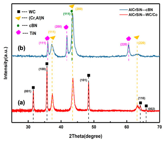
Figure 1.
XRD patterns of AlCrSiN coatings deposited on (a) WC-Co and (b) cBN substrates. The coatings present a (Cr,Al)N crystallographic phase.
The deposited AlCrSiN coatings were uniform and dense both on WC-Co and cBN substrates, as seen in Figure 2a,b. Based on the EDX composition maps, elements of chromium (Cr), aluminum (Al), and nitrogen (N) were detected in the coatings. Elements of wolfram (W), cobalt (Co), titanium (Ti), boron (B), and nitrogen (N) were detected on the substrates. The results are consistent with the compositions of coatings and substrates.
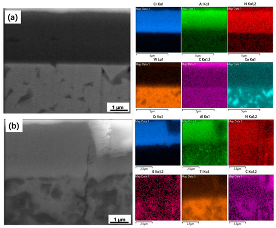
Figure 2.
SEM micrograph of the cross-section and the EDX composition maps for corresponding areas. (a) AlCrSiN coating deposited on WC-Co substrate, (b) AlCrSiN coating deposited on cBN substrate together with the platinum layer to avoid the waterfall effect during milling procedure, and the crack in the coating and substrate was caused by the scratch test.
The measured thicknesses of the coatings are presented Table 2, showing similar values for both substrates. Consequently, the geometry is similar, and the results of the mechanical testing can be compared for both substrates.
Table 2.
Thickness of coating–substrate systems.
3.2. Mechanical Properties of the Coating–Substrate Systems
The results of nano-indentation are presented in Table 3, and the images of nano-indentation imprints are presented in Figure 3. According to Table 3, the AlCrSiN coatings exhibited similar values when deposited on different substrates, WC-Co and cBN, which means the mechanical properties of the coatings were not altered by the substrates. Some circumferential cracks, shown in Figure 3c, appeared at the inner edge of the nano-indentation and indicated that the cracking resistance of the AlCrSiN coating deposited on the cBN substrate may be lower than the sample with the WC-Co substrate, probably due to the higher stiffness of the substrate.
Table 3.
Mechanical properties of coating–substrate systems.
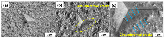
Figure 3.
SEM images of nano-indentation, (a) AlCrSiN coating deposited on WC-Co substrate, (b) AlCrSiN coating deposited on cBN substrate, (c) magnification of the circumferential cracks highlighted with dotted circle on the image (b).
3.3. Adhesion Tests
Figure 4 presents the scratch tracks of the two coating–substrate systems obtained via optical microscopy together with the magnification of failure events via SEM. It is seen how plastic deformation, microcracking, and delamination occurred as the load was increased. First, cracking of the coating (indicated as LC1) was present in both samples. For the WC-Co substrate, stick–slip deformation was induced via compressive stress and appeared at the contour. As the load increased, transverse cracks, which were induced by tensile stress, appeared until spallation of the coating occurred; this load is defined as the second critical load (LC2), implying failure of the interface between coating and substrate [34]. Interfacial failure occurred much earlier in the cBN substrate (seen in Figure 4b,c) with clear spallation of the coating [35,36]. Fracture features were also different, with more substrate exposure in the case of cBN.
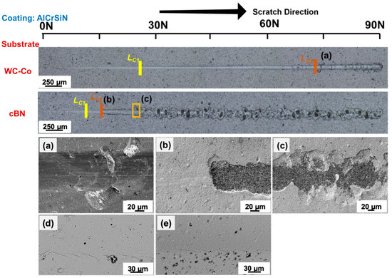
Figure 4.
The optical profile and SEM images of failure after scratch tests of AlCrSiN coatings deposited on WC-Co and cBN, two different substrates. The second critical loads (LC2) are magnified in the images of (a,b), respectively. (c) shows the scenario in which cBN substrate was totally exposed after receiving more of the second critical load. The first critical loads (LC1) are magnified in the images of (d,e), respectively.
The scratch crack propagation resistance (CPRs) was calculated to rationalize the scratch resistance of the coatings in the coating–substrate systems, calculated using Equation (2) [37,38].
where LC1 is the first critical load and the start of lateral crack, and LC2 is the second critical load and the start of the coating delamination or spallation. The results are presented in Figure 4.
The critical stress σc was calculated using Equation (3).
where dc is the track width at LC2, μ is the friction coefficient calculated using the friction force, and νf is the Poisson ratio of the coatings [39]. The surface energy of the known interfacial crack (adhesion energy) is then defined using Equation (4) [39,40,41,42].
where t and E are the thickness and elastic modulus of coatings, respectively. The experimental values of t and E are presented in Table 1 and Table 2, respectively.
The results of CPR and adhesion energy are presented in Table 4. The AlCrSiN coating deposited on the WC-Co substrate presents higher CPR values, which means better scratch resistance. The adhesion energy between the AlCrSiN coating and WC-Co substrate was higher than for the cBN substrate, which illustrates better adhesion strength between the coating and WC-Co substrate. Calculation of adhesion energy followed the method from the previous study by S. J. Bull et al., and the values of Gc were similar to previous research on similar coatings such as CrAlN and AlCrSiN [34,40,43,44].
Table 4.
Scratch crack propagation resistance and adhesion energy of both coated samples.
Figure 5 presents the SEM images after the contact damage tests at a series of normal loads of 98 N, 196 N, and 294 N. For the sample of AlCrSiN coating deposited on the WC-Co substrate, the coating does not show any cracking. At loads of 196 N and higher, radial cracking and delamination can be observed. In the case of the cBN substrate, delamination is clearly present even for the smaller loads. As the load increases, more spalling of the coating is observed, similar to previous research on similar materials [34,45,46].
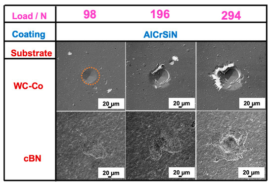
Figure 5.
SEM images of the contact damage tests of AlCrSiN coatings at 98 N, 196 N, and 294 N with a Rockwell C tip for both substrates. Contact area of the coating on WC-Co for 98 N is indicated.
In order to further inspect the mechanisms of this delamination, lower loads of 9.8 N and 29.4 N were conducted on the cBN substrate sample, and the surface was observed using SEM, as presented in Figure 6. Under a lower normal load, delamination of the AlCrSiN coating appeared on the surface. Cohesive failure of the coating was evident with normal load of 9.8 N, as seen in Figure 6(a2), where it can be seen that the coating had fractured, without exposing the substrate. However, when the normal load was increased to 29.4 N, the coating was totally delaminated from the cBN substrate, as seen in Figure 6(b2). This conclusion is xposure of the cBN substrate indicates that adhesion failure between the AlCrSiN coating and cBN substrate was produced at that load. In any case, this illustrates worse mechanical performance as compared to the WC-Co substrate.
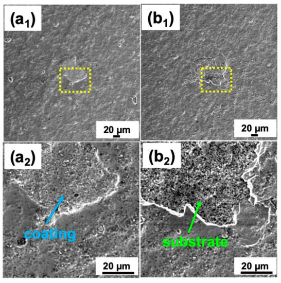
Figure 6.
SEM images of the contact damage tests of AlCrSiN coatings deposited on cBN substrates with a Rockwell C tip. The failures in (a1,a2) were under 9.8 N and in (b1,b2) were at 29.4 N.
3.4. Mechanical Response under Contact Loading
Both materials were indented using a spherical indenter with a monotonic load and cyclic load to investigate the contact mechanical response under different conditions [47,48,49]. Figure 7 shows the SEM images of the damage failure induced via spherical indentation under monotonic loads. The surface of the cBN substrate sample presented discontinuous cracks under the monotonic loads of 2000 N. When the load increased up to 3000 N, the edge of the indentation formed a complete crack circle. However, for the samples deposited on the WC-Co, the discontinuous cracks and complete ring cracks appeared at larger loads of 5000 N and 6000 N, respectively, which shows the form and shape of the cracks over the load of the first damage. In agreement with previous results, the contact resistance of the coatings deposited on the WC-Co is larger than for the coatings deposited on the cBN substrates.
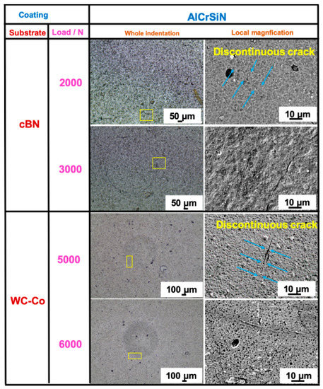
Figure 7.
SEM images of damage features of AlCrSiN coatings deposited on WC-Co and cBN substrates induced via spherical indentation under different loads (2000 N, 3000 N, 5000 N, and 6000 N).
Based on the results, fatigue tests were conducted at the loads causing first damage, that is 5000 N and 2000 N for the samples on WC-Co and cBN substrates, respectively, as presented in Figure 8. For the cBN substrate, the ring crack was fully developed, and partial delamination could be observed, as seen in Figure 8(b1). However, for the WC-Co substrate, the ring crack was not fully developed, even after 103 cycles under 5000 N, the same load that appeared for first damage, as seen in Figure 8(a1). The results indicate that the AlCrSiN coatings deposited on the WC-Co substrate performed better under contact fatigue than the same coatings deposited on the cBN substrates.
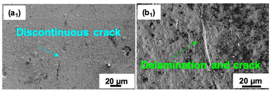
Figure 8.
SEM images of spherical indentation cyclic loads with 103 cycles. (a1) AlCrSiN coating deposited on WC-Co substrate under the load of 5000 N; (b1) AlCrSiN coating deposited on cBN substrate under the load of 2000 N.
In order to further explore the direction of crack development caused by fatigue tests, the cross-section at the complete circle crack were performed using FIB, as shown in Figure 9. The ring cracks of the surface penetrated both the AlCrSiN coatings and both substrates. For the cBN substrate, a part of each coating was removed from the surface, as seen in Figure 9(b1), with a delaminated area of coating forming a valley shape. However, as seen in Figure 8(b1), the coatings were completely spalled from the cBN substrate, indicating that cohesive and adhesive failure of the coatings coexisted under contact fatigue loading. As seen in Figure 9(b2), the ceramic binder of the cBN substrate suffered microcracking due to the cyclic loads. For the samples deposited on the WC-Co substrate, only some transverse cracks appeared in the coating and substrate, which kept their original morphologies, as seen in Figure 9(a1,a2); the overall shape of coating–substrate system remained intact, and transverse cracks only appeared inside the coatings but not at the interfaces. Another interesting phenomenon can be observed in Figure 9(b1,b2), where the interface between the AlCrSiN coatings and cBN substrate was not flat but rather kept the tortuous morphology of the surface of the cBN substrate. Multiple cracks were observed in the ceramic binder of the cBN substrate, and the substrate appeared to be crushed along with the periphery of the boron nitride particles.
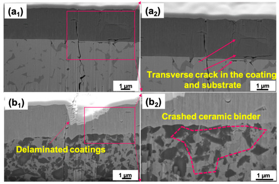
Figure 9.
Cross-section SEM images of indentations and morphologies of fatigue cracks. (a1,a2) present the sample of AlCrSiN coating deposited on WC-Co substrate under the cyclic load of 6000 N with 103 cycles, (b1,b2) present the sample of AlCrSiN coating deposited on cBN substrate under the cyclic load of 3000 N with 103 cycles. (a2,b2) are the enlarged views of the corresponding areas in (a1,b1), respectively.
4. Discussion
From the results presented above, it is clear that coatings deposited on cBN have a lower mechanical performance as compared with the same coatings deposited on WC-Co substrates. Adhesion strength, as measured by scratch testing, is lower, implying that the coating delamination is easier in this substrate. In addition, different fracture features are evident for both substrates.
This lower adhesion can be partially attributed to the difference in chemical nature of each substrate. However, it is also seen that the structural integrity of the coating is also more affected when deposited on the cBN substrate under contact loadings, albeit having the same composition and intrinsic mechanical properties such as hardness and elastic modulus. In this sense, the differences in mechanical properties of the two substrates induce different contact damage responses and damage evolutions with increasing loads (as seen in Figure 7 and Figure 8). As seen in Table 2, cBN is harder than WC-Co. If the contact loading is performed at relatively high loads (such as the contact damage and scratch tests) deformation will be a combined response of both coating and substrate. Because of the cBN substrate’s higher hardness, its deformation will be concentrated close to the surface, which will lead to a larger amount of microcracking in order to accommodate the deformation [50]. These results are in agreement with Sveen et al. [27], who also observed much lower scratch resistance and different damage mechanisms for the cBN substrate. In the case of contact loads, the results are also in agreement with the work of S. Gordon et al. [21]. who studied TiN/TiAlN-coated cBN under contact loads and found that failure appears near the interface between the AlCrSiN coating and the cBN substrate. In Figure 9, in the FIB cross-section, one can see the existence of microcracking of the substrate, which can explain the failure of the substrate observed by these authors and in this work as well.
From the above results, it is clear that the contact resistance of coated hard materials is a multifaceted issue, in which the microstructures of both coating and substrate, as well as interfacial adhesion, play a key role.
5. Conclusions
The mechanical performances of the AlCrSiN coatings deposited on WC-Co and cBN, two different substrates, have been comparatively characterized. Our main conclusions can be summarized as:
(1) Nano-indentation results show the same value of mechanical properties and thicknesses of the coatings when deposited on both substrates as well as chemical compositions. The crystal structure of AlCrSiN coatings deposited on different substrates was mainly (Cr,Al)N solid solution. Si was not detected using XRD due to its relatively small amounts or the formation of an amorphous phase. Therefore, the coating structure is not affected by the substrate.
(2) Through microscratch tests, AlCrSiN coatings deposited on the WC-Co substrate presented better adhesion than those deposited on the cBN substrate. This is further evidenced by the contact damage tests, during which a part of an AlCrSiN coating totally detached from the cBN substrate at 29.4 N, but the delamination of the AlCrSiN coating on the cBN substrate appeared at 294 N.
(3) The results of mechanical response under contact Hertzian loads presented that AlCrSiN coatings deposited on the WC-Co substrate perform better resistance to monotonic loads and cyclic loads than those coatings deposited on the cBN substrate. Using SEM and FIB, cohesive and adhesive failures of AlCrSiN coatings were observed under cyclic loads when deposited on the WC-Co and cBN substrates, respectively.
The differences in mechanical performances of the same coating deposited on different substrates depend on both adhesion strengths and distinct mechanical properties of the substrates.
Author Contributions
Conceptualization, J.L., E.J.-P. and J.F.d.A.; experiments, J.L., M.S., S.G., E.A. and J.F.d.A.; analysis of the results, all authors; writing—original draft preparation, J.L.; writing—review and editing, E.J.-P., L.L., J.F.d.A. and J.L.; funding acquisition, E.J.-P. All authors have read and agreed to the published version of the manuscript.
Funding
This research was funded by The Spanish Ministry of Science, Innovation and Universities through grants PGC2018-096855-B-C41, PGC2018-096855-A-C44 and PID2021-126614OB-100.
Institutional Review Board Statement
Not applicable.
Informed Consent Statement
Not applicable.
Data Availability Statement
The data that support the findings of this study are available from the corresponding authors upon reasonable request.
Acknowledgments
The authors would like to thank R. M’ Saoubi from SECO Tools for kindly providing the substrates. The work was funded by The Spanish Ministry of Science, Innovation and Universities through grants PGC2018-096855-B-C41, PGC2018-096855-A-C44 and PID2021-126614OB-100.
Conflicts of Interest
The authors declare no conflict of interest. The funders had no role in the design of the study; in the collection, analyses, or interpretation of data; in the writing of the manuscript; or in the decision to publish the results.
References
- Rech, J.; Djouadi, M.; Picot, J. Wear resistance of coatings in high speed gear hobbing. Wear 2001, 250, 45–53. [Google Scholar] [CrossRef]
- Fellah, M.; Aissani, L.; Zairi, A.; Samad, M.A.; Nouveau, C.; Touhami, M.Z.; Djebaili, H.; Montagne, A.; Iost, A. Thermal treatment effect on structural and mechanical properties of Cr–C coatings. Trans. IMF 2018, 96, 79–85. [Google Scholar] [CrossRef]
- Spor, S.; Jäger, N.; Meindlhumer, M.; Hruby, H.; Burghammer, M.; Nahif, F.; Mitterer, C.; Keckes, J.; Daniel, R. Evolution of structure, residual stress, thermal stability and wear resistance of nanocrystalline multilayered Al0.7Cr0.3N-Al0.67Ti0.33N coatings. Surf. Coat. Technol. 2021, 425, 127712. [Google Scholar] [CrossRef]
- Chen, Y.; Zhang, Z.; Yuan, T.; Mei, F.; Lin, X.; Gao, J.; Chen, W.; Xu, Y. The synergy of V and Si on the microstructure, tribological and oxidation properties of AlCrN based coatings. Surf. Coat. Technol. 2021, 412, 127082. [Google Scholar] [CrossRef]
- Li, C.; Bing, Y.; Xu, Y.; Fei, P.; Zhou, L.; Yong, D. Improved thermal stability and oxidation resistance of Al–Ti–N coating by Si addition. Thin Solid Films 2014, 556, 369–375. [Google Scholar]
- Mcintyre, D.; Greene, J.E.; Hakansson, G.; Sundgren, J.E.; Munz, W.D. Oxidation of metastable single-phase polycrystalline Ti0.5Al0.5N films: Kinetics and mechanisms. J. Appl. Phys. 1990, 67, 1542–1553. [Google Scholar] [CrossRef]
- Veprek, S.; Männling, H.-D.; Jilek, M.; Holubar, P. Avoiding the high-temperature decomposition and softening of (Al1−xTix)N coatings by the formation of stable superhard nc-(Al1−xTix)N/a-Si3N4 nanocomposite. Mater. Sci. Eng. A 2004, 366, 202–205. [Google Scholar] [CrossRef]
- Park, J.H.; Chung, W.S.; Cho, Y.-R.; Kim, K.H. Synthesis and mechanical properties of Cr–Si–N coatings deposited by a hybrid system of arc ion plating and sputtering techniques. Surf. Coat. Technol. 2004, 188–189, 425–430. [Google Scholar] [CrossRef]
- Veprek, S.; Veprek-Heijman, M.; Karvankova, P.; Prochazka, J. Different approaches to superhard coatings and nanocom-posites. Thin Solid Films 2005, 476, 1–29. [Google Scholar] [CrossRef]
- Baptista, A.; Silva, F.J.G.; Porteiro, J.; Míguez, J.L.; Pinto, G. Sputtering Physical Vapour Deposition (PVD) Coatings: A Critical Review on Process Improvement and Market Trend Demands. Coatings 2018, 8, 402. [Google Scholar] [CrossRef]
- Leyendecker, T.; Lemmer, O.; Esser, S.; Ebberink, J. The development of the PVD coating TiAlN as a commercial coating for cutting tools. Surf. Coat. Technol. 1991, 48, 175–178. [Google Scholar] [CrossRef]
- Oliver, W.C.; Pharr, G.M. An improved technique for determining hardness and elastic modulus using load and dis-placement sensing indentation experiments. J. Mater. Res. 1992, 7, 1564–1583. [Google Scholar] [CrossRef]
- Vidakis, N.; Antoniadis, A.; Bilalis, N. The VDI 3198 indentation test evaluation of a reliable qualitative control for layered compounds. J. Mater. Process. Technol. 2003, 143–144, 481–485. [Google Scholar] [CrossRef]
- Mishra, S.K.; Ghosh, S.; Aravindan, S. Investigations into friction and wear behavior of AlTiN and AlCrN coatings deposited on laser textured WC/Co using novel open tribometer tests. Surf. Coat. Technol. 2020, 387, 125513. [Google Scholar] [CrossRef]
- Wu, Z.; Huan, J.; Geng, D.; Ye, R.; Wang, Q. Investigation on plastic deformation of arc-evaporated AlCrSiN and AlCrSiON nanocomposite films by indentation. Surf. Coat. Technol. 2022, 441, 128570. [Google Scholar] [CrossRef]
- Berger, L.M. Coatings by Thermal Spray—ScienceDirect. Compr. Hard Mater. 2014, 1, 471–506. [Google Scholar]
- Gant, A.J.; Morrell, R.; Wronski, A.S.; Jones, H.G. Edge toughness of tungsten carbide based hardmetals. Int. J. Refract. Met. Hard Mater. 2018, 75, 262–278. [Google Scholar] [CrossRef]
- Huang, Y.; Chou, Y.K.; Liang, S.Y. CBN tool wear in hard turning: A survey on research progresses. Int. J. Adv. Manuf. Technol. 2007, 35, 443–453. [Google Scholar] [CrossRef]
- Cook, M.W.; Bossom, P.K. Trends and recent developments in the material manufacture and cutting tool application of polycrystalline diamond and polycrystalline cubic boron nitride. Int. J. Refract. Met. Hard Mater. 2000, 18, 147–152. [Google Scholar] [CrossRef]
- Bushlya, V.; Lenrick, F.; Bjerke, A.; Aboulfadl, H.; Thuvander, M.; Ståhl, J.-E.; M’Saoubi, R. Tool wear mechanisms of PcBN in machining Inconel 718: Analysis across multiple length scale. CIRP Ann. 2021, 70, 73–78. [Google Scholar] [CrossRef]
- Gordon, S.; Roa, J.J.; Rodriguez-Suarez, T. Infuence of microstructural assemblage of the substrate on the adhesion strength of coated PcBN grades. Ceram. Int. 2022, 48, 22313–22322. [Google Scholar] [CrossRef]
- Pozuelo, S.G. Microstructural and Mechanical Properties Correlation at the Micro- and Nanometric Length Scale of Different cBN Grade. Master’s Thesis, Universitat Politècnica de Catalunya, Barcelona, Spain, July 2018. [Google Scholar]
- Gordon, S.; García-Marro, F.; Rodriguez-Suarez, T.; Roa, J.; Jiménez-Piqué, E.; Llanes, L. Spherical indentation of polycrys-talline cubic boron nitride (PcBN): Contact damage evolution with increasing load and microstructural effects. Int. J. Refract. Met. Hard Mater. 2023, 111, 106115. [Google Scholar] [CrossRef]
- Gordon, S.; Besharatloo, H.; Wheeler, J.; Rodriguez-Suarez, T.; Roa, J.; Jiménez-Piqué, E.; Llanes, L. Micromechanical mapping of polycrystalline cubic boron nitride composites by means of high-speed nanoindentation: Assessment of microstructural assemblage effects. J. Eur. Ceram. Soc. 2023, 43, 2968–2975. [Google Scholar] [CrossRef]
- Gao, Y.; Cai, F.; Lu, X.; Xu, W.; Zhang, C.; Zhang, J.; Qu, X. Design of cycle structure on microstructure, mechanical properties and tribology behavior of AlCrN/AlCrSiN coatings. Ceram. Int. 2022, 48, 12255–12270. [Google Scholar] [CrossRef]
- Tuchida, K.; Wathanyu, K.; Surinphong, S. Thermal Oxidation Behavior of TiAlCrSiN and AlCrTiN Films on HastelloyX. In Proceedings of the 2012 International Conference on Nanotechnology Technology and Advanced Materials (ICNTAM 2012), Hong Kong, China, 12–13 April 2012. [Google Scholar]
- Sveen, S.; Andersson, J.; M’saoubi, R.; Olsson, M. Scratch adhesion characteristics of PVD TiAlN deposited on high speed steel, cemented carbide and PCBN substrates. Wear 2013, 308, 133–141. [Google Scholar] [CrossRef]
- Mosquera, A.; Mera, L.; Fox-Rabinovich, G.; Martínez, R.; Azkona, I.; Endrino, J. Advantages of nanoimpact fracture testing in studying the mechanical behavior of CrAl (Si) N coatings. Nanosci. Nanotechnol. Lett. 2010, 2, 352–356. [Google Scholar] [CrossRef]
- Oliver, W.C.; Pharr, G.M. Measurement of hardness and elastic modulus by instrumented indentation: Advances in understanding and refinements to methodology. J. Mater. Res. 2004, 19, 3–20. [Google Scholar] [CrossRef]
- Kayali, Y.; Taktak, S. Characterization and Rockwell-C adhesion properties of chromium-based borided steels. J. Adhes. Sci. Technol. 2015, 29, 2065–2075. [Google Scholar] [CrossRef]
- Zhu, L.-H.; Song, C.; NI, W.-Y.; Liu, Y.-X. Effect of 10% Si addition on cathodic arc evaporated TiAlSiN coatings. Trans. Nonferrous Met. Soc. China 2016, 26, 1638–1646. [Google Scholar] [CrossRef]
- Ho, W.Y.; Hsu, C.H.; Chen, C.W.; Wang, D.Y. Characteristics of PVD-CrAlSiN films after post-coat heat treatments in nitrogen atmosphere. Appl. Surf. Sci. 2011, 257, 3770–3775. [Google Scholar] [CrossRef]
- Gui, Y.; Zhao, J.; Chen, J.; Jiang, Y. Preparation and Characterization of Ni Spines Grown on the Surface of Cubic Boron Nitride Grains by Electroplating Method. Materials 2016, 9, 153. [Google Scholar] [CrossRef] [PubMed]
- Liang, J.; Almandoz, E.; Ortiz-Membrado, L.; Rodríguez, R.; de Ara, J.F.; Fuentes, G.G.; Llanes, L.; Jiménez-Piqué, E. Mechanical Performance of AlCrSiN and AlTiSiN Coatings on Inconel and Steel Substrates after Thermal Treatments. Materials 2022, 15, 8605. [Google Scholar] [CrossRef]
- ASTM C1624-22; Standard Test Method for Adhesion Strength and Mechanical Failure Modes of Ceramic Coatings by Quantitative Single Point Scratch Testing. ASTM International: West Conshohocken, PA, USA, 2010.
- Zhang, X.; Tian, X.-B.; Zhao, Z.-W.; Gao, J.-B.; Zhou, Y.-W.; Gao, P.; Guo, Y.-Y.; Lv, Z. Evaluation of the adhesion and failure mechanism of the hard CrN coatings on different substrates. Surf. Coat. Technol. 2019, 364, 135–143. [Google Scholar] [CrossRef]
- Zhang, S.; Sun, D.; Fu, Y.; Du, H. Effect of sputtering target power on microstructure and mechanical properties of nano-composite nc-TiN/a-SiNx thin films. Thin Solid Films 2004, 447, 462–467. [Google Scholar] [CrossRef]
- Kabir, M.S.; Munroe, P.; Zhou, Z.; Xie, Z. Scratch adhesion and tribological behaviour of graded Cr/CrN/CrTiN coatings synthesized by closed-field unbalanced magnetron sputtering. Wear 2017, 380–381, 163–175. [Google Scholar] [CrossRef]
- Wang, Q.; Zhou, F.; Zhou, Z.; Li, L.K.-Y.; Yan, J. An investigation on the crack resistance of CrN, CrBN and CrTiBN coatings via nanoindentation. Vacuum 2017, 145, 186–193. [Google Scholar] [CrossRef]
- Bull, S.; Rickerby, D. New developments in the modelling of the hardness and scratch adhesion of thin films. Surf. Coat. Technol. 1990, 42, 149–164. [Google Scholar] [CrossRef]
- Huang, Y.-C.; Chang, S.-Y.; Chang, C.-H. Effect of residual stresses on mechanical properties and interface adhesion strength of SiN thin films. Thin Solid Films 2009, 517, 4857–4861. [Google Scholar] [CrossRef]
- Chang, S.-Y.; Tsai, H.-C.; Chang, J.-Y.; Lin, S.-J.; Chang, Y.-S. Analyses of interface adhesion between porous SiOCH low-k film and SiCN layers by nanoindentation and nanoscratch tests. Thin Solid Films 2008, 84, 5334–5338. [Google Scholar] [CrossRef]
- Wang, Q.; Zhou, F.; Yan, J. Evaluating mechanical properties and crack resistance of CrN, CrTiN, CrAlN and CrTiAlN coatings by nanoindentation and scratch tests. Surf. Coat. Technol. 2016, 285, 203–213. [Google Scholar] [CrossRef]
- Patnaik, L.; Maity, S.R.; Kumar, S. Evaluation of Crack resistance and Adhesive Energy of AlCrN and Ag doped a-C Films deposited on Chrome Nitrided 316 LVM Stainless Steel. Adv. Mater. Process. Technol. 2022, 8, 1048–1069. [Google Scholar] [CrossRef]
- Casas, B.; Anglada, M.; Sarin, V.K.; Llanes, L. TiN coating on an electrical discharge machined WC-Co hardmetal: Surface integrity effects on indentation adhesion response. J. Mater. Sci. 2006, 41, 5213–5219. [Google Scholar] [CrossRef]
- Yang, J.; Odén, M.; Johansson-Jõesaar, M.P.; Llanes, L. Influence of substrate microstructure and surface finish on cracking and delamination response of TiN-coated cemented carbides. Wear 2016, 352, 102–111. [Google Scholar] [CrossRef]
- Tarrés, E.; Ramírez, G.; Gaillard, Y.; Jiménez-Piqué, E.; Llanes, L. Contact fatigue behavior of PVD-coated hardmetals. Int. J. Refract. Met. Hard Mater. 2009, 27, 323–331. [Google Scholar] [CrossRef]
- Llanes, L.; Tarrés, E.; Ramírez, G.; Botero, C.A.; Jiménez-Piqué, E. Fatigue susceptibility under contact loading of hardmetals coated with ceramic films. Procedia Eng. 2010, 2, 299–308. [Google Scholar] [CrossRef]
- Zheng, Y.; Fargas, G.; Lavigne, O.; Serra, M.; Coureaux, D.; Zhang, P.; Yao, Z.; Zhang, Q.; Yao, J.; Llanes, L. Contact fatigue of WC-6%wtCo cemented carbides: Influence of corrosion-induced changes on emergence and evolution of damage. Ceram. Int. 2022, 48, 5766–5774. [Google Scholar] [CrossRef]
- Kong, Y.; Tian, X.; Gong, C.; Chu, P.K. Enhancement of toughness and wear resistance by CrN/CrCN multilayered coatings for wood processing. Surf. Coat. Technol. 2018, 344, 204–213. [Google Scholar] [CrossRef]


Disclaimer/Publisher’s Note: The statements, opinions and data contained in all publications are solely those of the individual author(s) and contributor(s) and not of MDPI and/or the editor(s). MDPI and/or the editor(s) disclaim responsibility for any injury to people or property resulting from any ideas, methods, instructions or products referred to in the content. |
© 2023 by the authors. Licensee MDPI, Basel, Switzerland. This article is an open access article distributed under the terms and conditions of the Creative Commons Attribution (CC BY) license (https://creativecommons.org/licenses/by/4.0/).