Article

Study on Machining Parameters Analysis and Optimization for Material Removal Rate and Surface Roughness During Dry Turning of AZ31B Magnesium Alloy Using Ceramic-Coated Carbide Tool Inserts

by
Thabiso Moral Thobane
1,
Sujeet Kumar Chaubey
1,2 and
Kapil Gupta
1,*
1
Department of Mechanical and Industrial Engineering Technology, University of Johannesburg, Johannesburg 2028, South Africa
2
Marwadi University Research Centre, Department of Mechanical Engineering, Marwadi University, Rajkot 360003, Gujrat, India
*
Author to whom correspondence should be addressed.
Ceramics 2025, 8(2), 38; https://doi.org/10.3390/ceramics8020038
Submission received: 21 March 2025 / Revised: 13 April 2025 / Accepted: 16 April 2025 / Published: 18 April 2025

Abstract

:
This paper presents research findings on the turning of AZ31B magnesium alloy using ceramic-coated tungsten carbide tool inserts in a dry environment. Fifteen experiments were conducted according to the Box–Behnken design (BBD) for the straight turning of AZ31B magnesium alloy to investigate the variations in two important machinability indicators, i.e., material removal rate ‘MRR’ and mean roughness depth ‘RZ’, with variations in cutting speed ‘CS’, feed rate ‘fr’, and depth of cut ‘DoC’. The cutting speed and feed rate had the maximum influence on the mean roughness depth and material removal rate, respectively. To address the challenge of optimizing conflicting machining responses, desirability function analysis (DFA) and grey relational analysis (GRA) were employed to identify the optimal turning parameters for conflicting machinability indicators or responses. These techniques enabled the simultaneous maximization of the material removal rate and the minimization of the mean roughness depth, ensuring an effective balance between productivity and surface quality. The optimal turning conditions—cutting speed of 90 m/min, feed rate of 0.2 mm/rev, and depth of cut of 1.0 mm—yielded the best multiperformance results with an MRR of 18,000 mm3/min and an RZ of 2.21 µm. Scanning electron microscope (SEM) analysis of the chip and flank surface of the cutting tool insert used in the confirmation tests revealed the formation of band-saw-type continuous chips and tool wear caused by adhesion and abrasion.

Graphical Abstract

1. Introduction

Magnesium (Mg) is considered one of the leading green materials of the 21st century [1]. Magnesium is the third most widely used structural element after steel and aluminum. Magnesium (Mg) is a lightweight, silvery-white metal with about two-thirds the density of aluminum. It has a low melting point, good electrical conductivity, moderate thermal conductivity, and high chemical reactivity. Magnesium alloy is a metal that is made by combining magnesium with other metals, such as aluminum, zinc, or manganese, to improve its properties [2,3]. Some key characteristics of magnesium alloys include being lightweight, having a high strength-to-weight ratio, corrosion resistance, good machinability, and poor fatigue resistance. Magnesium alloys are important materials for various engineering applications, such as automotive, aerospace, and electronics. Common magnesium alloys include the AZ series (Al-Zn), AM series (Al-Mn), and ZM series (Zn–rare earth) [4].
AZ31B is abundantly available, and its high strength-to-weight ratio and low density make it ideal for a variety of applications, including orthopedic implants, aircraft fuselages, and electronic products [5,6]. AZ31B magnesium alloys undergo extensive machining during product manufacturing, presenting several challenges. The major machining issues include flammability (fire risk), chip formation (clogging and tool wear), rapid tool wear (due to abrasiveness), low thermal conductivity (leading to overheating and poor surface finish), surface defects (burr formation), and work hardening (increasing cutting forces and reducing efficiency). Additionally, at high temperatures, the material is prone to chipping and adhering to tool faces. To mitigate these issues, appropriate actions are needed, such as (i) optimizing machining parameters like cutting speed, feed rate, depth of cut, and coolant application; (ii) using suitable tools with enhanced cutting ability, such as coated or treated carbide or ceramic cutting tools; and (iii) applying specific lubricants or coolants to prevent overheating and improve surface quality [7,8].
Several conventional machining methods are used to machine magnesium alloys in both wet and dry environments. However, many processes that rely on coolants (wet environments) are unsustainable and have detrimental effects on the environment. Using coolants in machining processes introduces several negative impacts, including environmental pollution, health and safety risks, and corrosion. Additionally, issues such as improper chip disposal and health hazards from contaminated fluids arise. The need for increased maintenance, including cleaning and filtration to prevent clogs, contamination, and system failures, further contributes to operational challenges. Ultimately, these factors lead to higher overall machining costs. This drives researchers to explore sustainable machining methods for soft materials, such as magnesium, intending to achieve improved part quality, enhanced sustainability, and increased process productivity. Dry machining is one such technique that eliminates the need for lubrication, significantly reducing machining costs while helping to maintain a cleaner and greener environment by minimizing emissions [9,10]. Dry machining is the process of machining materials without cutting fluids, such as coolants or lubricants. It reduces environmental impact and operational costs by eliminating coolant disposal, filtration, and maintenance. This method also enhances safety by reducing exposure to harmful fluids and helps to prevent corrosion and contamination. Dry machining offers several advantages; however, it is often inadequate for achieving optimal machinability, especially with challenging materials or complex processes. Successful outcomes require integrating additional techniques, such as specialized tools and optimized machining parameters. For instance, coated cutting tools can enhance tool life and performance, but appropriate combinations of machining parameters may be needed [11,12].
Ceramic-coated tool inserts are cutting tools coated with a thin layer of ceramic material, such as alumina (Al2O3), titanium carbonitride (TiCN), or other hard ceramics, to enhance their performance in machining processes. These tool inserts provide numerous benefits, including enhanced wear resistance for a longer tool life, especially when machining abrasive materials. Their thermal stability allows them to perform at high temperatures, making them ideal for high-speed cutting. The coating also offers oxidation resistance, reduces friction, improves chip flow, and enhances the surface finish. These inserts support higher cutting speeds, improve productivity, and are corrosion-resistant, making them suitable for harsh environments. Their versatility allows the machining of various materials, including tough alloys, making them a top choice for precision, durability, and performance in demanding operations [13,14]. Some important past work on magnesium alloy machining is discussed below.
Deswal and Kant performed laser heat-assisted dry turning of an AZ31B-grade magnesium alloy [15]. They compared the results with the outcomes of plain turning and found a significant enhancement in machinability, in terms of obtaining a lower roughness, machining force, and tool wear, with laser assistance. Carou et al. [16] carried out the dry turning of UNS M11917 magnesium alloy at varying turning combinations and found feed rate ‘fr’ to be the most influencing parameter on surface roughness. They reported keeping the maximum temperature below 50 °C and setting the machining parameters accordingly for better machinability prospects. Rubio et al. [17,18] used tool inserts of varying coatings to face-turn magnesium alloy in the absence of lubricants. They obtained a high productivity at high values of cutting parameters. For the lowest surface roughness, they obtained a 0.04 mm/rev feed rate, 280 rpm spindle speed, and a TP2500 coating grade as the optimum combination of process parameters. Guo et al. [19] found a significant influence of the depth of cut and feed rate on the machinability of AZ91D alloy. A recent study on the turning of AZ91 magnesium alloy reported the successful minimization of cutting forces [20]. It was recommended to prevent the adhering of chips to the tool face and avoid machining at high speed. A previous article [21] presented an investigation on the wear of the tool inserts and the morphology of the chips while cutting AZ31B magnesium in a dry environment under the same set of conditions reported in the present article.
The literature review indicates that magnesium is a soft and flammable material and, therefore, is prone to ignition. In a dry environment, this may increase the machining risks. To obtain the best machinability indicators, an optimum combination of parameters is desirable. Moreover, previous attempts at dry machining AZ31B magnesium alloys are scarce. The review of past studies reveals several key research gaps, including (i) the limited application of multi-response optimization techniques, particularly for the simultaneous optimization of conflicting responses such as the material removal rate and mean roughness depth; (ii) limited details on the usage of ceramic-coated tool inserts in dry turning operations; (iii) a predominant focus on average surface roughness, with minimal consideration of other better and important surface quality indicators such as mean roughness depth ‘RZ’; (iv) a lack of comparative analysis between optimization methods like desirability function analysis (DFA) and grey relational analysis (GRA); and (v) limited validation of findings through confirmation experiments. The present study attempts to fill the gap and explores the dry turning of the AZ31B magnesium alloy using a thin film of ceramic-coated carbide tool inserts. The primary goal is to enhance the machinability of AZ31B magnesium alloy by maximizing the material removal rate (MRR) and minimizing the mean roughness depth (RZ). The specific objectives of this research are (i) to explore the sustainable straight turning of AZ31B alloy under dry conditions, ensuring minimal tool wear and eliminating fire risks; (ii) to analyze the effects of three key machining parameters—cutting speed (CS), feed rate (fr), and depth of cut (DoC)—i.e., the mean roughness depth ‘RZ’ and productivity (i.e., MRR); (iii) to apply multi-response optimization techniques (DFA and GRA) to identify optimal turning parameters for simultaneously maximizing productivity (MRR) and minimizing surface roughness (RZ); (iv) to validate the optimized results through confirmation tests; and (v) to examine the tool flank wear and chip morphology obtained during the confirmation experiments.
This study contributes to the scientific understanding of the dry machining of AZ31B magnesium alloy by systematically applying advanced multi-response optimization techniques (DFA and GRA) to simultaneously enhance surface quality and productivity. By identifying the optimal combination of turning parameters for maximizing MRR and minimizing RZ, this research offers a validated framework for sustainable and efficient machining. Additionally, it provides new insights into tool wear behaviour and chip morphology under dry conditions using ceramic-coated carbide inserts.

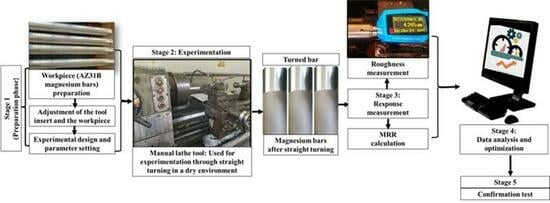
2. Experimental Details
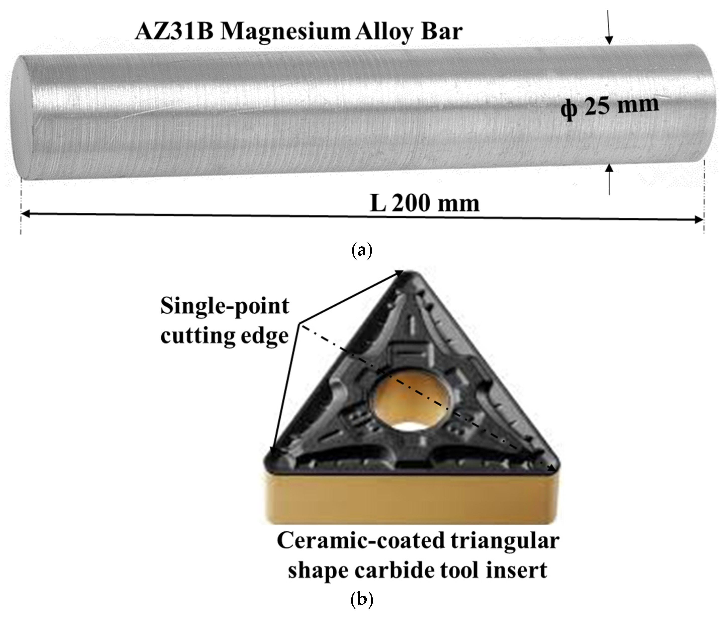
2.1. Material

In this study, experiments were conducted on a Colchester manual lathe machine (manufacturer: Colchester Machine Tool Solutions; model: Mascot 1600, city and country: West Yorkshire, United Kingdom) performing straight turning with thin ceramic-film-coated tungsten carbide tool inserts under dry conditions. The work material used was round bars of AZ31B magnesium alloy. A total of eight bars, each with a diameter of 20 mm and a length of 200 mm, were employed for the experimentation. The chemical composition (in % wt.) of the AZ31B magnesium alloy bars was as follows: Mg—97%, Al—2.5%, Zn—0.6%, Mn—0.2%, Si—0.1%, Cu—0.05%, Ca—0.04%, Fe—0.005%, and Ni—0.005%. Sieeso (TNMG160408-MT HS8125) (manufacturer: Zhuzhou Sieeso Advanced Materials Corporation Limited; city and country: Zhuzhou, China) carbide tool inserts, coated with a thin alumina ceramic film, were used for the straight turning of AZ31B magnesium alloy bars under dry conditions. The inserts featured a triangular (T) shape with negative (N) geometry and multi-use (M) characteristics, offering three effective cutting edges (single-point), as shown in Figure 1. These inserts were coated with medium-thickness titanium carbonitride (TiCN) and a thin layer of alumina (Al2O3) with a combined ceramic coating hardness of approximately 3000 HV. This coating enhances performance in high-speed and high-temperature machining applications. It improves wear resistance and toughness, allowing the insert to withstand high cutting temperatures and to extend the tool life, especially in heavy-duty operations. These inserts are widely used in turning operations due to their durability and performance under demanding conditions, offering a long tool life, excellent thermal stability, and oxidation resistance. Their versatility makes them suitable for machining a wide range of materials. Figure 1 shows the three-dimensional views of the cylindrical AZ31B magnesium alloy bar and ceramic-coated tool insert.

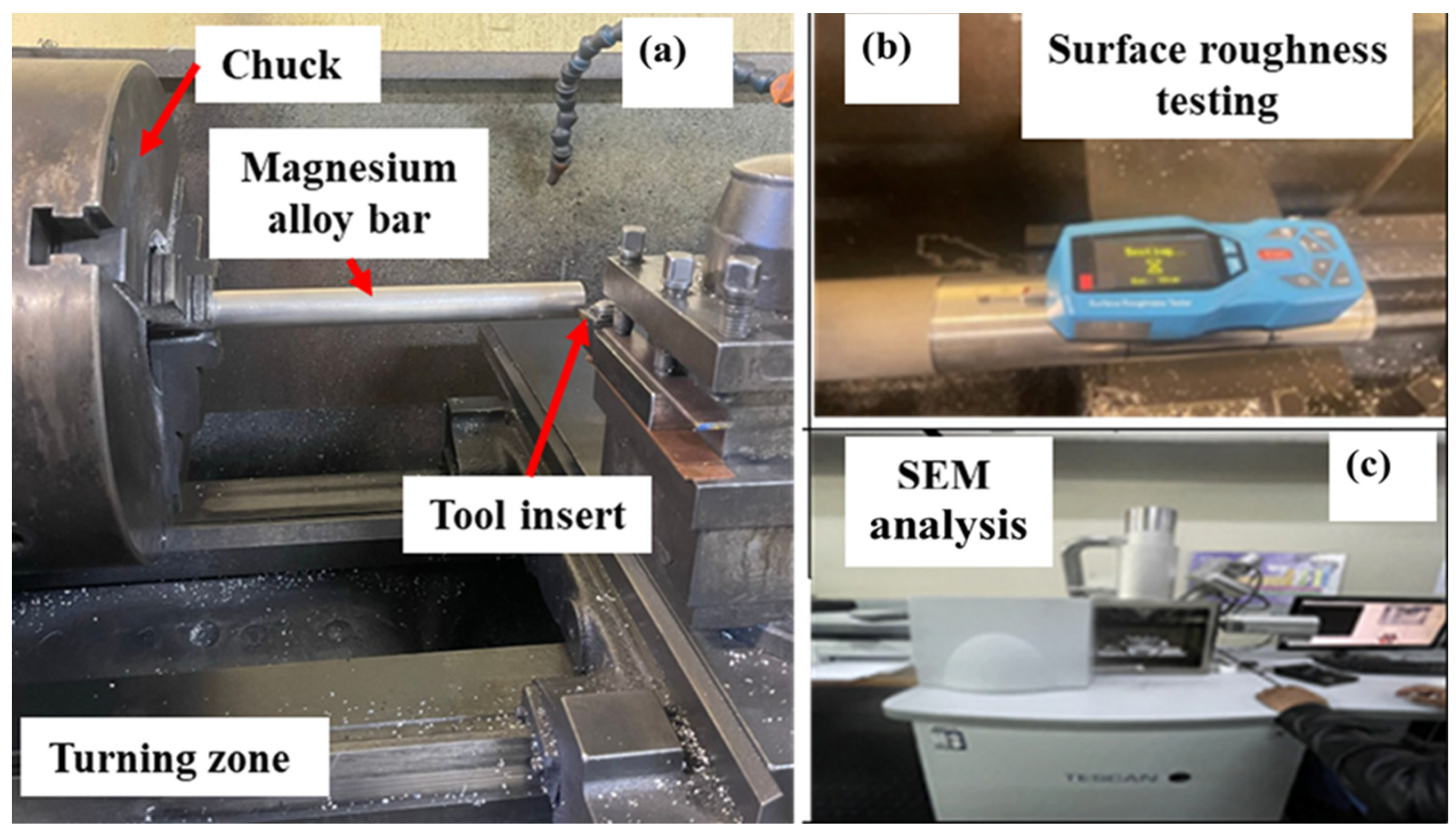
2.2. Experimentation and Measurement

A Colchester Mascot 1600 manual lathe machine (12.5 HP, 1600 RPM) was used for the straight turning of AZ31B magnesium alloy bars with ceramic-coated carbide tool inserts, as shown in Figure 2. Fifteen machining combinations were designed using the Box–Behnken Design (BBD), as detailed in Table 1. The selected machining parameters included cutting speeds (CS) at 65, 90, and 115 m/min; feed rates (fr) at 0.1, 0.15, and 0.2 mm/rev; and depths of cut (DoC) at 0.5, 0.75, and 1.0 mm [21]. Each experiment was conducted for 15 min and repeated twice. The material removal rate (MRR) and surface roughness, i.e., mean roughness depth ‘RZ’, were considered two important indicators for evaluating the machinability of AZ31B magnesium alloy. MRR represents the volume of material removed in the form of chips. The following equation was used to calculate the MRR:
M R R = C u t t i n g s p e e d F e e d r a t e × D e p t h o f c u t
The surface roughness value presents the amount of irregularity in the machined surface and is responsible for its performance while in use [22]. The mean roughness depth ‘RZ’ was used to determine the surface quality. Surface roughness was measured using the ART300 portable tester (manufacturer: AJR-NDT Corporation Limited; city and country: Xingtai, China). Measurements were taken with a 5 µm diameter stylus, using a Gaussian filter with a cut-off length of 0.8 mm and an evaluation length of 2 mm. Three measurements were taken across the machining direction on the turned magnesium bar, and their average values were taken into consideration. For tool wear measurements, ISO recommendations were followed and a 600 µm threshold of flank wear was considered as the end of tool life. Both chip morphology and tool flank wear were investigated on the TESCAN VEGA3 scanning electron microscope ‘SEM’ (manufacturer: TESCAN; city and country: Brno, Czech Republic). Figure 2 presents the experimental setup used in the present work.

3. Results and Discussion

The combinations of variable turning parameters for the manual lathe tool, designed based on the BBD-RSM with fifteen experimental runs, along with the average values of the measured responses from two replicates for each run, are presented in Table 1. Statistical testing of the model terms is conducted using analysis of variance (ANOVA), as shown in Table 2. ANOVA is conducted using a 95% confidence interval (p < 0.05) to assess the significance of the developed models, turning parameters, and their interactions for each response. The results of the analysis of variance (ANOVA), as presented in Table 2, yield the following interpretations: the ANOVA test is a key statistical tool for assessing data fit, model adequacy, and identifying influential parameters [23].
  • The developed quadratic model and linear model for MRR and RZ, respectively, are significant because the p-values are less than 0.05, as per the 95% confidence interval.
  • Only CS is found to be statistically significant for RZ. However, all variables are found to be statistically significant for MRR.
  • The square term of cutting speed is found to be significant for the mean roughness depth ‘RZ’.
  • The R-squared values of the developed MRR and RZ models are close to 1, confirming their strong predictive accuracy and reliability.
  • Adequate precision values above 4 indicate a desirable signal-to-noise ratio. The MRR and Rz models show values of 24.93 and 7.26, respectively, confirming that the developed models have adequate signals and are suitable for prediction.
  • The predicted R-squared value for the MRR model is in good agreement with the adjusted R-squared (difference < 0.2), indicating a strong correlation between the experimental and predicted values.
  • A normal distribution of the data is confirmed in Figure 3, with all fifteen residuals closely aligning with the mean line. Measured data points are represented in different colours based on their value ranges. In Figure 3a,b, red, green, and blue data points indicate high, intermediate, and low values of MRR and RZ, respectively.
  • Empirical Equations (1) and (2) are prediction models for MRR and RZ, respectively.
The empirical equations derived for the responses are as follows:
(i) For the material removal rate ‘MRR’:
M R R m m 3 m i n = 2050 + 112.5 C S + 67,500 f r + 13,500 D o C
(ii) The equation for the mean roughness depth ‘RZ’:
R z µ m = + 8.63 0.205   C S + 9.43   f r 1.873   D o C + 0.158   C S   f r + 0.0152   C S   D o C   5.8   f r   D o C + 0.0012   C S 2 40.67   f r 2 + 1.373 D o C 2
Empirical Equations (1) and (2) are the developed models for predicting the material removal rate (MRR) and mean roughness depth (RZ), respectively, based on the various combinations of turning parameters listed in Table 1. The predicted values of MRR and RZ are compared with the corresponding experimental values in Table 1 to validate the accuracy of the models. Figure 4 presents the variation in the experimental and predicted values of the considered responses across the experimental runs. Figure 4a,b compare the material removal rate (MRR) and mean roughness depth (Rz), respectively, with the blue and orange lines indicating the experimental and predicted values. The vertical axis shows the response values, while the horizontal axis denotes the experimental runs, each representing a unique set of turning parameters. A close agreement between the experimental and predicted results confirms the reliability of the models. These results indicate that empirical Equations (2) and (3) demonstrate strong predictive accuracy, as evidenced by the close agreement between the experimental and predicted values of MRR and RZ. This indicates that the models effectively capture the influence of turning parameters on the responses. However, the models are limited to the specific range of parameters used in the experiments and may not generalize well beyond these conditions. Additionally, they do not account for potential nonlinear interactions or external factors such as tool wear or material inconsistencies.

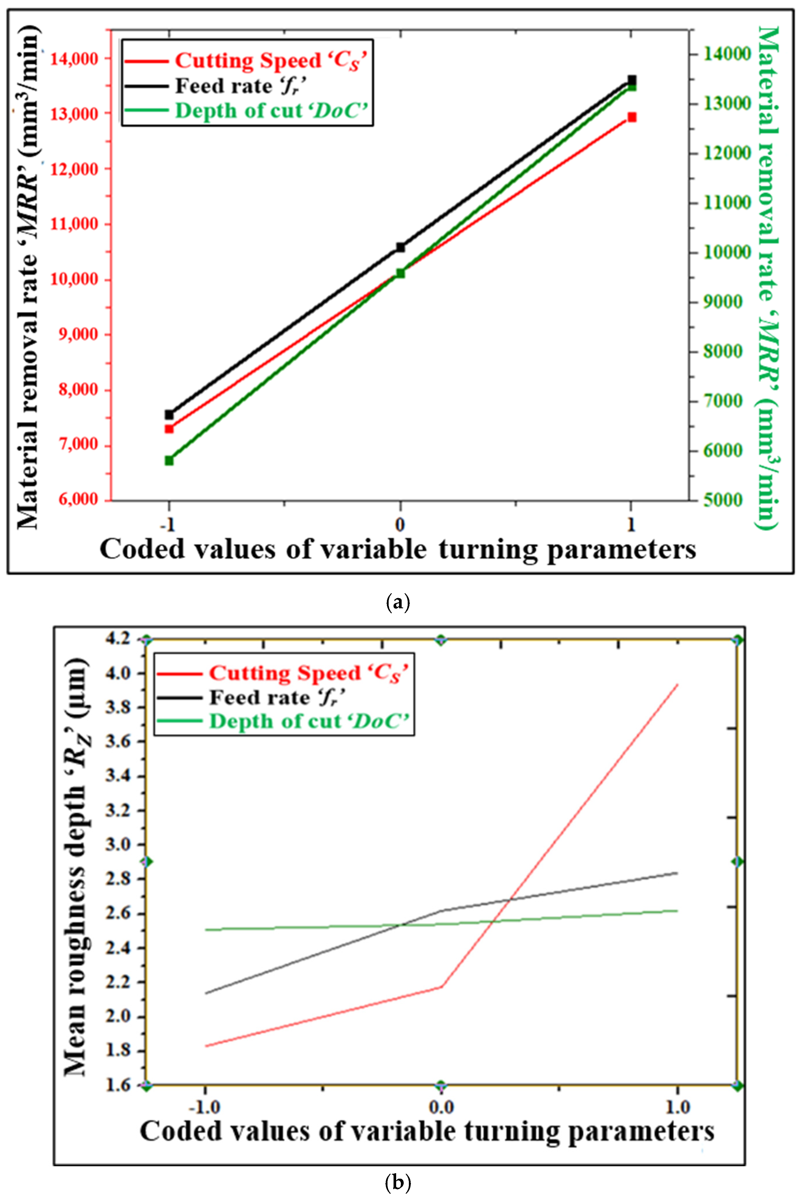
Influence of Variable Turning Parameters on Responses

Figure 5a,b illustrate the variation in MRR and RZ with three selected turning parameters, i.e., Cs, fr, and DoC. The coded values of the variable turning parameters are on the abscissa, whereas the actual values of the machinability indicators, i.e., MRR and RZ, are on the ordinates. The variation in MRR with DoC is depicted on the secondary axis in Figure 5a, while the variation in MRR with CS and fr is depicted on the primary axis. It is evident from Figure 5a that MRR increases with an increase in the turning parameters. Machining at high CS, fr, and DoC results in the maximum MRR. An increased spindle speed, movement of the tool along the workpiece, and the insertion of the tool at higher depths and at high values of turning parameters cause the removal of higher amounts of work materials and chips and, hence, increase the material removal rate. Figure 5b shows that the mean roughness depth ‘RZ’ increases with CS, fr, and DoC. CS is the most influential on RZ. RZ increases linearly with the cutting speed and varies rapidly in the 90–115 m/min speed zone. Turning of the magnesium alloy at high speed causes the generation of heat and thereby causes the softening of the tool and the further chipping of the work particles. Due to magnesium being adhered on the tool face, continuous machining deteriorates the turned work surfaces further, which is reflected in the high surface roughness. Excessive heat generation due to high friction, work bar wobbling, and vibration and chattering corresponding to high values of cutting parameters results in increased surface roughness.

4. Optimization

Finding the optimal combination of variable parameters is a critical task in any machining operation, as it aims to achieve both high surface quality and productivity simultaneously [24,25]. Desirability function analysis (DFA)- and grey relational analysis (GRA)-based techniques are used for optimization to maximize the material removal rate ‘MRR’ and minimize the mean roughness depth ‘RZ’ simultaneously. Both DFA and GRA are valuable for multi-response optimization due to their complementary approaches. DFA is a goal-oriented technique that prioritizes responses using weights [26], while GRA is a relation-based method which focuses on closeness to ideal values without needing predefined preferences [27]. Their optimization results may differ slightly, offering broader insight and more reliable decision-making when used together. DFA is particularly well suited for optimizing conflicting responses simultaneously, as it allows the assigning of weights and importance levels to each response, helping to balance trade-offs based on specific goals. GRA is best suited when responses have similar goals or importance, as it treats all responses uniformly by measuring their closeness to the ideal solution without requiring predefined weights. DFA identifies the exact optimum values within a specified range of variable parameters, although these values may not correspond exactly to the levels used in the experimental design. However, they may align with the available machine’s incremental values or be close to them. In contrast, GRA-based optimization typically results in parameter values that closely match one of the experimental runs defined in the design, making it more directly applicable to the experimental setup.
In this study, the objective function is the larger-the-better type and the smaller-the-better type for the material removal rate and mean roughness depth, respectively. Therefore, Equations (4) and (5) are used to compute the desirability of MRR and RZ for the ith experimental observation and a target value equal to a maximum value of MRR and a minimum value of RZ identified from experimental values, as given in Table 1, is used.
For the maximization of the material removal rate (i.e., larger-the-better type)
d j = y j L O L w j
For the minimization of the mean roughness depth (i.e., smaller-the-better type)
d j = H y j H O w j
C d = d 1 ,   d 2 ,   d 3 . d t 1 t = j = 1 t d j 1 W j
where ‘dj’ is the desirability of all machining performance indicators ‘yj’; ‘Cd’ is the collective desirability function; O is the objective value; H and L are the permissible upper and lower values of the ith response, respectively; wi is weightage allocated to the response yi; and t is the total number of responses. To achieve the best possible combination, a collective desirability (Cd) value that is closer to 1 is chosen. Equations (7) and (8) are used to compute the desirability for the jth combination of MRR and RZ by assigning an equal weightage of 0.5.
For the maximization of MRR (i.e., larger-the-better type)
d M R R J = M R R J M R R m i n M R R m a x M R R m i n 0.5
For the minimization of the RZ (i.e., smaller-the-better type)
d R Z j = R Z m a x   R Z j   R Z m a x   R Z m i n   0.5
The maximum MRR and RZ values used are 4.64 µm and 18,000 mm3/min, respectively, while the corresponding minimum values are 1.57 µm and 4500 mm3/min, respectively.
The following Equations (9) and (10) are used to compute the collective desirability function ‘Cdj’ for the jth combination of turning parameters.
D j = d M R R j 0.5   d R Z j 0.5 1 0.5 + 0.5
D j = d F W j 0.5   d R Z j 0.5
The optimum results obtained from DFA are a 77.39 m/min cutting speed, a 0.2 mm/rev feed rate, a 1.0 mm depth-of-cut, a 15,451 mm3/min MRR, and a 2.11 µm RZ. Since the optimum value of the cutting speed obtained from the DFA is different from the standard values available in the manual lathe machine tool, the adjacent standard values closest to the optimum are chosen for the confirmation runs, as shown in Table 3.
In grey relational analysis (GRA)-based optimization, Equations (11) and (12) are used for the objective functions (i.e., maximizing and minimizing) after normalizing the experimental results.
For maximizing MRR (higher-the-better)
M R R i j = Y j k min ( Y j ) max Y j min ( Y j )
For minimizing RZ (lower-the-better)
R Z i j = max Y j Y j k max Y j min ( Y j )  
where max (Yj) and min (Yj) are the maximum and minimum values of jth performance indicators among the fifteen experiments shown in Table 2. Equation (5) is also used to calculate the grey coefficient ‘GCjk’ values for the jth response of the kth experiment.
G C j k =   Delta min + γ   Delta max   D e l t a j k + γ   D e l t a m a x
where ‘ γ ’ denotes the distinguishing coefficient, which has a value range of 0 to 1. It is usually allocated to 0.5 to give each machining performance indicator equal weightage. By considering the average values of ‘GCjk’ of all of the machining performance indicators corresponding to the kth experimental run, Equation (6) is used to compute the grey relational grade (Gg). In Equation (6), p indicates the total number of performance indicators.
G g j = k = 1 p G C j k
In GRA, the highest value of Gg indicates the optimal combination. Therefore, experimental run 9 has the highest GRG of 0.83 and is regarded as the best turning combination, consisting of 90 m/min CS, 0.2 mm/rev fr, and 1.0 mm DoC (i.e., run 9).
Since the optimum cutting speed obtained from the DFA differs from the cutting speed levels listed in the experimental table and the standard values available in the manual lathe tool, the nearest standard value is selected for the confirmation runs, as shown in Table 3. After adjusting to the closest standard cutting speed, the same turning combination is obtained from both DFA and GRA.
The optimum results obtained from the best desirability (i.e., 0.99) and GRG (0.83) are validated by conducting two confirmation runs (CEs) using an optimal turning combination. The average values of the machining performance indicators obtained from the confirmation runs are used. Table 3 shows the optimum results, as well as the values of MRR and RZ obtained from the confirmation runs. The average (i.e., CEs 1 and 2) MRR and RZ values for DFA are 15,451 mm3/min and 2.36 µm, respectively, and for GRA, they are 18,000 mm3/min and 2.21 µm, respectively. The percentage difference between the optimal and confirmation results is under 10%, indicating a good agreement between the predicted and actual values. The higher MRR percentage difference for DFA, shown in Table 3, is attributed to significant variations in cutting speed values during the confirmation test, resulting from the selection of the adjacent standard cutting speed values available on the manual lathe machine.

Analysis of Chip Morphology and Tool Wear

Chip formation in machining occurs when a material is removed from a workpiece, influenced by the cutting speed, feed rate, depth of cut, and the materials of the tool and workpiece [28,29], whereas tool wear in turning is the gradual deterioration of the cutting tool due to friction, heat, and mechanical stress. It can occur as abrasive, adhesive, thermal, chemical, or notch wear, impacting the surface finish, accuracy, and machining efficiency. Monitoring wear and optimizing cutting conditions can help to reduce its effects. SEM analysis of the removed metal from the workpiece and tool insert flank face is conducted. Figure 6a shows the formation of band-saw-type continuous chips under optimal parameters. AZ31B, being a ductile material, deforms plastically under cutting forces, causing chips to stretch and curl into long, continuous forms. Moderate cutting speeds promote this behaviour, favouring plastic deformation over fragmentation. Continuous chips cause abrasive and adhesive wear, with severe magnesium adhesion on the tool flank. In contrast, small, discontinuous chips lead to adhesion or chipping, with major wear due to abrasion. Figure 6b presents scanning electron micrographs of tool insert wear, showing magnesium particle adhesion on the tool flank and wear from both adhesion and abrasion (Figure 6b,c). Ceramic coatings significantly enhance tool performance by severely mitigating the wear mechanisms of abrasion, adhesion, and diffusion. The high hardness and thermal stability of ceramic-coated tools improves their resistance to abrasive wear, while their low chemical reactivity and smooth surface help to reduce adhesive wear. Additionally, ceramic coatings serve as effective barriers against heat and chemical interactions, thereby minimizing diffusion wear. Compared to uncoated inserts, these properties lead to extended tool life, improved cutting stability, and increased overall machining efficiency.

5. Conclusions

This study has investigated the dry cutting of AZ31B magnesium alloy on a manual lathe using ceramic-coated carbide tool inserts. The analysis and effects of the machining parameters and their optimization for surface roughness and material removal rate have been reported. The summary of this research is as follows:
  • Successful fire-ignition-free machining was achieved, achieving a higher material removal rate without compromising the surface finish.
  • Cutting speed was found to have the most impact on mean roughness depth, whereas feed rate was more prominent for material removal rate.
  • MRR and RZ both increased with an increase in variable turning parameters.
  • A 90 m/min Cs, 0.2 mm/rev fr, and 0.1 mm DoC were obtained as the optimum combination/settings of the machining parameters from GRA for the best surface quality, with a mean roughness depth RZ of 2.21 µm and a best productivity with MRR of 18,000 mm3/min.
  • The SEM study revealed the formation of band-saw-type continuous chips and flank wear due to adhesion and abrasion with the chipping of magnesium.
  • We recommend intermediate Cs (90 m/min) and higher values of fr (0.2 mm/rev) and DoC (1 mm) to obtain maximum productivity with a better surface finish for AZ31B magnesium alloy.
This study on the dry turning of AZ31B magnesium alloy bars had limitations, such as the use of a controlled set of turning parameters and the use of specific tool materials and coatings, which may have limited the generalizability of the findings to other machining conditions or tool types. While the dry environment offered sustainability benefits, it may also have resulted in a reduced tool life and surface quality compared to lubricated processes. Additionally, the absence of real-time monitoring and thermal analysis limited the ability to fully understand tool wear and material behaviour. These limitations opened up opportunities for future research, which could include (i) the machining of AZ31B magnesium alloy in dry environments using textured or treated tools; (ii) a comparative study of magnesium machining under different cutting environments; (iii) an investigation on the machining of AZ31B magnesium alloy in dry conditions using a wider range of tool materials and coatings, especially those designed for the high-performance machining of light alloys; (iv) utilizing advanced monitoring techniques (e.g., force, temperature, acoustic signals) to asses real-time tool wear and thermal effects; (v) an investigation on surface integrity and subsurface damage, including residual stresses, microhardness, and corrosion resistance, to assess the quality and performance of the magnesium alloy parts; and (vi) utilizing machine learning (ML) and finite element analysis (FEM) to develop predictive models for optimizing machining parameters and enhancing process efficiency and sustainability.

Author Contributions

Conceptualization, S.K.C. and K.G.; Methodology, T.M.T. and S.K.C.; Software, T.M.T. and S.K.C.; Validation, T.M.T. and S.K.C.; Formal analysis, T.M.T. and S.K.C.; Investigation, T.M.T. and S.K.C.; Data curation, T.M.T. and S.K.C.; Writing—original draft, T.M.T. and S.K.C.; Writing—review and editing, K.G.; Supervision, S.K.C. and K.G.; Project administration, K.G.; Funding acquisition, K.G. All authors have read and agreed to the published version of the manuscript.

Funding

This research is supported by the National Research Foundation (South Africa) under the NRF Grant For 2023–2028: Incentive Funding for Rated Researchers (IFRR), Grant No: 150892.

Institutional Review Board Statement

This study did not require ethical approval.

Informed Consent Statement

Not applicable.

Data Availability Statement

The original contributions presented in this study are included in the article. Further inquiries can be directed to the corresponding author.

Acknowledgments

The authors express their gratitude to the technicians and lab staff of the Department of Mechanical and Industrial Engineering Technology at the University of Johannesburg for their valuable support.

Conflicts of Interest

The authors declare no conflict of interest.

References

  1. Xu, J.; Shen, J.; Li, L.; Guo, G.; Zhu, X.; Meng, Y.; Chen, M. Milling machinability analysis of GW63K rare-earth magnesium alloys based on the concept of clean cutting. J. Mater. Res. Technol. 2023, 26, 9380–9391. [Google Scholar] [CrossRef]
  2. Tan, J.; Ramakrishna, S. Applications of Magnesium and Its Alloys: A Review. Appl. Sci. 2021, 11, 6861. [Google Scholar] [CrossRef]
  3. Prasad, S.V.S.; Prasad, S.B.; Verma, K.; Mishra, R.K.; Kumar, V.; Singh, S. The role and significance of Magnesium in modern day research—A review. J. Magnes. Alloys 2022, 10, 1–61. [Google Scholar] [CrossRef]
  4. Xu, J.; Shen, J.; Li, L.; Guo, G.; Zhu, X.; Meng, Y.; Chen, M. An investigation on tool performances in milling rare-earth magnesium alloys. Int. J. Adv. Manuf. Technol. 2024, 134, 4529–4537. [Google Scholar] [CrossRef]
  5. Carou, D.; Davim, J.P. Machining of Light Alloys: Aluminum, Titanium, and Magnesium; CRC Press: Boca Raton, FL, USA, 2019. [Google Scholar]
  6. Li, L.; Xu, J.; Guo, G.; Chen, M. Numerical study of the effects of tool parameters on the cutting temperature distribution and ignition risks of magnesium alloys. In Proceedings of the 1st International Conference on New Materials, Machinery and Vehicle Engineering; IOS Press: Amsterdam, The Netherlands, 2022; pp. 83–90. [Google Scholar] [CrossRef]
  7. Rosli, Y. A brief review on green machining. AIP Conf. Proc. 2024, 3161, 020034. [Google Scholar] [CrossRef]
  8. Bastas, A. Sustainable manufacturing technologies: A systematic review of latest trends and themes. Sustainability 2021, 13, 4271. [Google Scholar] [CrossRef]
  9. Guvenc, M.A.; Bilgic, H.H.; Mistikoglu, S. Identification of Chatter Vibrations and Active Vibration Control by Using the Sliding Mode Controller on Dry Turning of Titanium Alloy (Ti6al4v). Facta Univ. Ser. Mech. Eng. 2023, 21, 307–322. [Google Scholar] [CrossRef]
  10. Goindi, G.S.; Sarkar, P. Dry machining: A step towards sustainable machining—Challenges and future directions. J. Clean. Prod. 2017, 165, 1557–1571. [Google Scholar] [CrossRef]
  11. Milosevic, A.; Simunovic, G.; Kanovic, Z.; Simunovic, K.; Santosi, Z.; Sokac, M.; Vukelic, D. Comprehensive evaluation of dimensional deviation, flank wear, surface roughness and material removal rate in dry turning of c45 steel. Facta Univ. Ser. Mech. Eng. 2024, 22, 547–566. [Google Scholar] [CrossRef]
  12. Sandhu, P.; Goindi, G.S.; Chopra, S. Evaluation of dry machining, air-cooling conditions and MQL techniques as sustainable manufacturing processes for turning of aluminium 6061. Mater. Today Proc. 2022, 68, 791–798. [Google Scholar] [CrossRef]
  13. Rezende, B.A.; dos Santos, A.J.; Câmara, M.A.; do Carmo, D.J.; Houmard, M.; Rodrigues, A.R.; Campos Rubio, J.C. Characterization of Ceramics Coatings Processed by Sol-Gel for Cutting Tools. Coatings 2019, 9, 755. [Google Scholar] [CrossRef]
  14. Wang, Q.; Jin, Z.; Zhao, Y.; Niu, L.; Guo, J. A comparative study on tool life and wear of uncoated and coated cutting tools in turning of tungsten heavy alloys. Wear 2021, 482–483, 203929. [Google Scholar] [CrossRef]
  15. Deswal, N.; Kant, R. Machinability and surface integrity analysis of magnesium AZ31B alloy during laser assisted turning. J. Manuf. Process. 2023, 101, 527–545. [Google Scholar] [CrossRef]
  16. Carou, D.; Rubio, E.M.; Lauro, C.H.; Davim, J.P. Experimental investigation on finish intermittent turning of UNS M11917 magnesium alloy under dry machining. Int. J. Adv. Manuf. Technol. 2014, 75, 1417–1429. [Google Scholar] [CrossRef]
  17. Rubio, E.M.; Valencia, J.L.; Saá, A.J. Experimental study of the dry facing of magnesium pieces based on the surface roughness. Int. J. Precis. Eng. Manuf. 2013, 14, 995–1001. [Google Scholar] [CrossRef]
  18. Rubio, E.M.; Pipaón, J.M.S.D.; Villeta, M.; Sebastián, M.A. Study of surface roughness of pieces of magnesium UNS M11311 obtained by dry turning using ANOVA. Adv. Mater. Res. 2011, 264–265, 967–972. [Google Scholar] [CrossRef]
  19. Guo, X.; Teng, L.; Wang, W.; Chen, T. Study on the cutting properties about magnesium alloy when dry turning with kentanium cutting tools. Adv. Mater. Res. 2010, 102–104, 653–657. [Google Scholar] [CrossRef]
  20. Akgun, M. Measurement and optimization of cutting forces, surface roughness and temperature in turning of AZ91 Mg alloy. Sadhana 2023, 48, 60. [Google Scholar] [CrossRef]
  21. Thobane, T.M.; Chaubey, S.K.; Gupta, K. Analysis of Tool Wear and Chip Morphology during Turning of AZ31B Magnesium Alloy under Dry Environment. J. Manuf. Mater. Process. 2023, 7, 187. [Google Scholar] [CrossRef]
  22. Stanojković, J.; Radovanović, M. Influence of the Cutting Parameters on Force, Moment and Surface Roughness in The End Milling of Aluminum 6082-T6. Facta Univ. Ser. Mech. Eng. 2022, 20, 157–165. [Google Scholar] [CrossRef]
  23. Perec, A. Desirability function analysis (DFA) in multiple responses optimization of abrasive water jet cutting process. Rep. Mech. Eng. 2022, 3, 11–19. [Google Scholar] [CrossRef]
  24. Zolpakar, N.A.; Yasak, M.F.; Pathak, S. A review: Use of evolutionary algorithm for optimisation of machining parameters. Int. J. Adv. Manuf. Technol. 2021, 115, 31–47. [Google Scholar] [CrossRef]
  25. Jozić, S.; Bajić, D.; Dumanić, I.; Bagavac, Ž. Optimization for an efficient and highly productive turning process. Rep. Mech. Eng. 2021, 2, 212–221. [Google Scholar] [CrossRef]
  26. Montgomery, D.G. Design and Analysis of Experiments, 10th ed.; John Willey and Sons: Hoboken, NJ, USA, 2019; ISBN 978-1-118-14692-7. [Google Scholar]
  27. Chakraborty, S.; Datta, H.N.; Chakraborty, S. Grey relational analysis-based optimization of machining processes: A comprehensive review. Process. Integr. Optim. Sustain. 2023, 7, 609–639. [Google Scholar] [CrossRef]
  28. Suresh, R.; Basavarajappa, S.; Gaitonde, V.N. Experimental studies on the performance of multilayer coated carbide tool in hard turning of high strength low alloy steel. J. Mater. Res. 2015, 30, 3056–3064. [Google Scholar] [CrossRef]
  29. Kotiba, H. Highly-Ductile Magnesium Alloys: Atomistic-Flow Mechanisms and Alloy Designing. Materials 2019, 12, 1934. [Google Scholar] [CrossRef]
Figure 1. Three-dimensional view of AZ31B magnesium alloy cylindrical bar and ceramic-thin-film-coated carbide tool insert: (a) AZ31B magnesium alloy bar; and (b) ceramic-coated carbide tool insert.
Ceramics 08 00038 g001
Figure 2. Actual image of the experimental setup used and the measuring instruments: (a) turning zone; (b) surface measurement of the bar after turning; and (c) SEM for microstructural analysis.
Ceramics 08 00038 g002
Figure 3. Normal probability distribution graphs of residuals for machining performance indicators: (a) MRR and (b) RZ.
Ceramics 08 00038 g003
Figure 4. Variation in experimental and predicted responses across experimental runs: (a) material removal rate and (b) mean roughness depth.
Ceramics 08 00038 g004
Figure 5. Variation in machining performance indicators with turning variable parameters: (a) MRR and (b) RZ.
Ceramics 08 00038 g005
Figure 6. SEM images of (a) chip morphology; (b) tool flank wear, obtained when machining AZ31B magnesium at an optimum combination of parameters; and (c) enlarged view of tool flank wear.
Ceramics 08 00038 g006
Table 1. Experimental combinations for turning of Mg alloy (AZ31B) and corresponding values of MRR and RZ with grey relational grade.
Ex.
No.
Variable Machining ParametersMachining Performance IndicatorsGrey Relational Grade
(GRG)
MRR
(mm3/min)
Mean Roughness Depth ‘RZ’ (µm)
Cutting Speed ‘CS’ (m/min)Feed ‘f’ (mm/rev)Depth of Cut (mm) ‘DoC’ (mm)R1R2Average
(R1 + R2)
R1R2Average
(R1 + R2)
1900.150.7510,12510,12510,1251.982.322.150.59
2650.200.759750975097502.262.582.420.55
31150.150.508625862586254.233.994.110.40
4900.101.009000900090002.362.282.320.55
5650.151.009750975097501.811.631.720.68
6650.100.754875487548751.621.521.580.67
7900.200.509000900090002.292.032.160.58
81150.151.0017,25017,25017,2504.814.474.640.62
9900.201.0018,00018,00018,0002.452.272.360.83
10900.100.504500450045001.921.741.830.59
11900.150.7510,12510,12510,1252.312.072.190.59
12650.150.504875487548751.671.471.570.67
131150.200.7517,25017,25017,2504.614.314.460.62
141150.100.758625862586252.672.992.830.48
15900.150.7510,12510,12510,1252.312.112.210.58
Table 2. ANOVA results of responses selected for turning AZ31B magnesium alloy bars with a manual lathe using ceramic-coated carbide inserts.
For material removal rate ‘MRR’ (mm3/min)
SourceSSDFMSFpRemark
Model2.455 × 108 38.184 × 10774.44<0.0001Significant
CS6.328 × 10716.328 × 10757.56<0.0001Significant
fr9.112 × 10719.112 × 10782.88<0.0001Significant
DoC9.113 × 10719.113 × 10782.88<0.0001Significant
Residual1.209 × 107111.099 × 106
Lack of fit1.209 × 10791.344 × 106
Pure error0.00020.000
Cor total2.576 × 10814
R-Squared = 0.951, Adjusted R-Squared = 0.9503, Predicted R-Squared = 0.8995
PRESS = 2.590 × 10⁷, Adequate Precision = 24.932
For mean roughness depth ‘RZ’ (µm)
Model13.1591.4616.400.027Significant
CS0.2710.2661.170.3294Significant
fr0.03110.0310.140.7272
DoC0.01610.0160.070.8027
CS fr0.1610.1560.680.4461
CS DoC0.03610.0360.160.7073
fr DoC0.02110.0210.090.7738
(CS2)2.0312.0268.870.0308Significant
(fr2)0.03810.0380.170.6996
(DoC2)0.02710.0270.120.7440
Residual1.1450.228
Lack of fit1.1430.380407.100.0025Significant
Pure error1.87 × 10320.001
Cor total14.2914
R-Squared = 0.9201, Adjusted R-Squared = 0.7763, Predicted R-Squared = −0.2762
PRESS = 18.24, Adequate Precision = 7.433
Table 3. Results of DFA- and GRA-based optimization and confirmation experiments.
Turning DetailsOptimized Value Confirmation ResultsError
(%)
DFAGRAAvg. (CEl1 & E2)
DFAGRADFAGRA
Variable turning parametersCutting speed ‘CS’ (m/min)77.3990
Feed rate ‘fr’ (mm/rev)0.20.2
Depth-of-cut ‘DoC’ (mm)1.01.0
Performance indicatorsMaterial removal rate ‘MRR’ (mm3/min)15,45118,00018,00018,00016.490
Mean roughness depth ‘RZ’ (µm)2.112.362.262.217.16.4
Disclaimer/Publisher’s Note: The statements, opinions and data contained in all publications are solely those of the individual author(s) and contributor(s) and not of MDPI and/or the editor(s). MDPI and/or the editor(s) disclaim responsibility for any injury to people or property resulting from any ideas, methods, instructions or products referred to in the content.

